

Page 1
INSTALLATION AND SERVICE MUST BE PERFORMED BY A QUALIFIED TECHNICIAN.
IMPORTANT: SAVE FOR THE LOCAL ELECTRICAL INSPECTOR'S USE.
READ AND SAVE THESE INSTRUCTIONS FOR FUTURE REFERENCE.
.
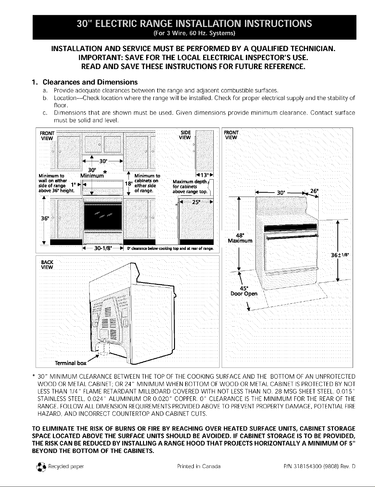
Clearances and Dimensions
a. Provide adequate clearances between the range and adjacent combustible surfaces.
b. Location--Check location where the range will be installed. Check for proper electrical supply and the stability of
floor.
c. Dimensions that are shown must be used. Given dimensions provide minimum clearance. Contact surface
must be solid and level.
FRONT
VIEW
VIEW / f
,RONT
Minimumto Minimum 1" Min)mum to 4F13"_,
wall on either ,, cabinetson Maximum depth
sideof range 1"_'1 18 either side for cabinets
above 36" height. _ of range, aDoverange top.
30"---_1_ 26'
48"
Maximum
_ 30-1/8"_ 6"clearancebelowcookJngtopandatrearofrange.
36+1/8•
BACK
VIEW
J
jf
45"
DoorOpen
_ r _ - r-r-
J
Terminal box"
f
J
* 30" MINIMUM CLEARANCE BETWEENTHETOPOFTHE COOKING SURFACEAND THE BOTTOM OF AN UNPROTECTED
WOOD OR METAL CABINET;OR 24" MINIMUM WHEN BOTTOM OFWOOD OR METAL CABINET ISPROTECTEDBY NOT
LESSTHAN 1/4" FLAME RETARDANTMILLBOARD COVERED WITH NOT LESSTHAN NO. 28 MSG SHEETSTEEL,0.015"
STAINLESSSTEEL,0.024" ALUMINUM OR0.020" COPPER.0" CLEARANCE ISTHE MINIMUM FOR THE REAROF THE
RANGE.FOLLOWALL DIMENSION REQUIREMENTSPROVIDEDABOVE TO PREVENTPROPERTYDAMAGE, POTENTIALFIRE
HAZARD, AND INCORRECTCOUNTERTOPAND CABINETCUTS.
TO ELIMINATE THE RISK OF BURNS OR FIRE BY REACHING OVER HEATED SURFACE UNITS, CABINET STORAGE
SPACE LOCATED ABOVE THE SURFACE UNITS SHOULD BEAVOIDED. IF CABINET STORAGE IS TO BE PROVIDED,
THE RISK CAN BEREDUCED BY INSTALLING A RANGE HOOD THAT PROJECTSHORIZONTALLY A MINIMUM OF 5"
BEYOND THE BOTTOM OF THE CABINETS.
_ Recycled paper Printed in Canada P/N 318154300 (9808) Rev. D
Page 2

2. Install Anti-Tip Bracket(s). (See instructions on
page 4.)
3. Serial Plate Information
The serial plate is located on the fl-ame and is visible
when the drawer is opened.
See the serial plate for the following information:
A,Model, lot and serial number of range.
B,Kilowatt rating (power requirements),
C,Voltage ratings,
_RISK OF FIRE OR ELECTRICAL SHOCK
MAY OCCUR IF AN INCORRECT SIZE RANGE CORD KIT
IS USED, THE INSTALLATION INSTRUCTIONS ARE NOT
FOLLOWED OR STRAIN RELIEFBRACKET ISDISCARDED.
This appliance may be connected by means of a power
supply cord. Only a power supply cord kit rated at 40
amperes, 125/250 volts minimum, and marked for use
with ranges shall be used, Cord must have three (3)
conductors, Terminals on end of wires must be either
closed loop or open-end spade lugs with upturned ends.
Cord must have strain relief clamp,
4. Electrical Connection Requirements
This appliance must be properly installed and grounded
by a qualified technician in accordance with the National
Electrical Code ANSI/NFPA No, 70--latest edition--and
local electrical code requirements.
This appliance may be connected by means of
permanent "Hard Wiring" or "Power Supply Cord Kit."
When hard wiring, do not leave excess wire in range
compartment. Excess wire in the range compartment
may not allow the access cover to be replaced properly,
and could create a potential electrical hazard if wires
become pinched. Connect only as instructed under
"WIRING INSTRUCTIONS" in sections 6 and 7. When
using flexible conduit or range cable, use flex connector
or range cable strain relief,
NOTE: Only use copper wire in connection to terminal
block,
4B. Models Requiring Power Supply Cord Kit
NOTE: MOBILE HOME INSTALLATION OR AREAS
WHERE LOCAL CODES DO NOT PERMIT GROUNDING
THROUGH NEUTRAL, A FOUR (4) CONDUCTOR
POWER CORD MUST BEUSED.
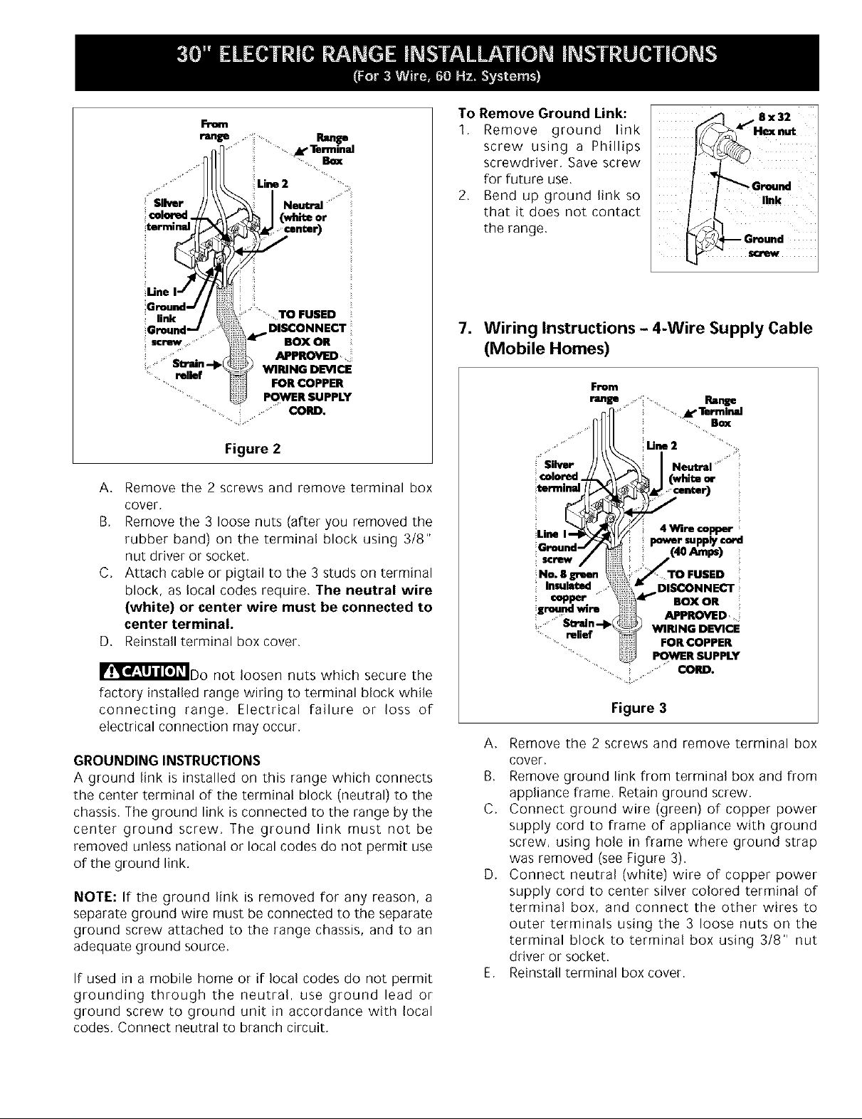
A 1-3/8" knock-out hole is provided at the bottom of the
range terminal box for connecting the power supply cord
kit to the range terminal block (see Figures 2 and 3).
5. Permanent Hard Wiring (3 or 4 Wires)
Insert the residence 3-wire power supply cable through
the 1-1/8" hole at the bottom of the range terminal box
(see Figure 2). For mobile home application or where
connections with a 3-wire power supply cable is not
allowed, use a 4-wire power supply cable (for
connections, see Figure 3), Use a U,L. approved strain
relief clamp to secure the cable to the terminal box,
6. Wiring Instructions - 3-Wire Supply Cable
_ELECTRICAL GROUND IS REQUIRED ON
THIS APPLIANCE,
This appliance is manufactured with the neutral terminal
connected to the frame. If local codes permit connection
of the frame grounding conductor to the neutral wire of
the copper power supply cord:
U.$, STYLE
Figure 1 - 3-Wire Cord Kit
Page 3
Rm'uEaD
Terminal
Line2
Neutral
en_
TO FUSED
DISCONNECT
i/Ak_ BOX OR
_ APPROVED
WIRING DEVICE
FOR COPPER
POWER SUPPLY
CORD.
Figure 2
A, Remove the 2 screws and remove terminal box
cover,
B, Remove the 3 loose nuts (after you removed the
rubber band) on the terminal block using 3/8"
nut driver or socket.
C, Attach cable or pigtail to the 3 studs on terminal
block, as local codes require. The neutral wire
(white) or center wire must be connected to
center terminal.
D, Reinstall terminal box cover.
IIl_l_!_r_'_F)o not loosen nuts which secure the
factory installed range wiring to terminal block while
connecting range, Electrical failure or loss of
electrical connection may occur.
GROUNDING INSTRUCTIONS
A ground link is installed on this range which connects
the center terminal of the terminal block (neutral) to the
chassis. The ground link is connected to the range by the
center ground screw, The ground link must not be
removed unless national or local codes do not permit use
of the ground link,
NOTE: If the ground link is removed for any reason, a
separate ground wire must be connected to the separate
ground screw attached to the range chassis, and to an
adequate ground source,
If used in a mobile home or if local codes do not permit
grounding through the neutral, use ground lead or
ground screw to ground unit in accordance with local
codes, Connect neutral to branch circuit,
To Remove Ground Link:
1, Remove ground link
screw using a Phillips
screwdriver, Save screw
for future use,
2, Bend up ground link so
that it does not contact
the range,
7. Wiring Instructions - 4-Wire Supply Cable
(Mobile Homes)
From
t_ge •. i¸, ,. Range
!! Silver
icolored
Line 4 WIre copper [
i screw
No. 8 green TO FUSED
Insulated DISCONNECT
copper BOX OR
!ground wire
Figure 3
Remove the 2 screws and remove terminal boxA,
cover,
B, Remove ground link from terminal box and from
appliance frame. Retain ground screw.
C, Connect ground wire (green) of copper power
supply cord to frame of appliance with ground
screw, using hole in frame where ground strap
was removed (see Figure 3).
D, Connect neutral (white) wire of copper power
supply cord to center silver colored terminal of
terminal box, and connect the other wires to
outer terminals using the 3 loose nuts on the
terminal block to terminal box using 3/8" nut
driver or socket.
E, Reinstall terminal box cover.
APPROVED
WIRING DEVICE
FOR COPPER
POWER SUPPLY
Page 4

8. Leveling the Range
Place a level on a properly installed oven rack. Adjust
the leveling legs under the bottom corners of the range
until the range is level.
9. Anti-Tip Bracket Installation Instructions
IMPORTANT SAFETYWARNING
To reduce the risk of tipping of the range, the range
must be secured to the floor by properly installed anti-tip
brackets and screws packed with the range. Those parts
are located in a plastic bag in the oven. Failure to install
the anti-tip brackets will allow the range to tip over if
excessive weight is placed on an open door or if a child
climbs upon it, Serious injury may result from spilled hot
liquids or from the range itself, Refer to the instructions
on this page for proper installation, If the range is moved
to a different location, the anti-tip brackets must also be
moved and installed with the range.
For the installation intructions refer to the anti-tip
bracket template in a plastic bag in the oven.
Page 5

LA INSTALACION Y EL SERVICIO DEBEN SER PROPORCIONADOS POR UN TECNICO
CALIFICADO. IMPORTANTE: GUARDE ESTAS INSTRUCCIONES PARA SU USO POR EL
INSPECTOR ELECTRICO LOCAL. LEA Y GUARDE ESTAS INSTRUCCIONES PARA FUTURA
REFERENCIA.
,
Espacios y dimensiones:
a, Proporcione espacios adecuados entre la estufa y las superficies combustibles adyacentes,
b, Ubicacion--Examine el lugar en el cual va a ser instalada la estufa, Determine la existencia de suministro electrico
adecuado y la estabilidad del piso,
c, Se deben usar las medidas indicadas, Las dimensiones indicadas proporcionan espacio minimo, La superficie de
contacto debe ser solida y estar a nivel,
VISTA
FRONTAL
30" --_1_ 26'
T
M_ximo
48"
36+1/8•
VISTA
POSTERIOR
/
/
/
Puerta abier[a -_
45
J
Caja terminal "
UN MINIMO DE 30" DEESPACIOENTRELA PARTESUPERIORDELA SUPERFICIEPARAESTUFARY ELFONDONO PROTEGIDO
DEUNGABINETEDEMETALOMADERA;O UNMINIMO DE24" CUANDO ELFONDODEMETALO MADERA DELGABINETEESTA
PROTEGIDOPOR NO MENOS DE114" DEMATERIALRETARDANTE,CON UNA HOJA DEACERODENO MENO8 MSG No,28,
0,015" DEACERO INOXIDABLE,0,024" DE ALUMINIO O 0,020" DECOBRE,O" E8 ELESPACIOMINIMO PARA LA PARTE
TRASERADELA ESTUFA,81GATODOSLOSREQUERIMIENTO8DEMEDIDA8 ANTESPROPORCIONADO8PARAEVITARDAKIO8
A LA PROPIEDAD:PELIGRODEINCENDIOSPOTENCIALE80 SUPERFICIESY CORTESDEGABINETESQUE8EANINCORRECTOS,
f
J
PARA ELIMINAR EL RIESGO DE QUEMADURAS O INCENDIO CUANDO TRATE DE ALCANZAR OBJETOS POR SOBRE
UNIDADES DE SUPERFICIE CALENTADAS, DEBE EVITARSE QUE LOS GABINES PARA ALMACENAMIENTO ESTEN
LOCALIZADOS ENCIMA DE LA SUPERFICIE DE LA ESTUFA. SI EXISTEN GABINETES DE ALMACENAMIENTO, EL RIESGO
PUEDE SER REDUCIDO INSTALANDO UNA CAMPANA DE ESTUFA QUE SE PROYECTE EN FORMA HORIZONTAL A UNA
DISTANCIA MINIMA DE 5" MAS ALLA DEL FONDO DE LOS GABINETES.
_ Papel reciclado Impreso en Canada P/N 318154300 (9808) Rev. D
Page 6

2. Instale los soportes antivuelco. (vet
instrucciones en la pagina 4,)
3. Placa de Identificacibn
Esta placa de identificacion esta Iocalizada sobre el
marco y se puede ver cuando la gaveta esta abierta,
Consulte la placa de identificacion para obtener la
siguiente informacion:
A,Numeros de modelo, partida y serie de la estufa,
B,Tasa de kilovatios (requerimientos de energia,)
C,Tasa de voltaje,
4. Requisitos de conexibn el_ctrica
Este aparato debe estar instalado en forma apropiada y
puesto a tierra por un tecnico calificado, de acuerdo con el
National Electric Code (Codigo Nacional de Electricidad)
ANSI/NFPA No, 70 --t]ltima edicion-- y con los
requerimientos de electricidad de los codigos locales,
Este aparato puede ser conectado por medio de una
extension a un tomacorriente local permanente o por medio
de "Juego de Cordon para el Suministro de Energia"
Cuando se use la extension, no deje exceso de alambre en
el compartimiento de la estufa. Si se deja exceso de
alambre en el compartimiento, esto no permitira que la
cubierta de acceso sea cerrada en forma apropiada, lo cual
puede crear un riesgo electrico potencial si se perforan los
alambres, Conecte este aparato solamente de acuerdo con
las "INSTRUCCIONES PARA ALAMBRADO" que aparecen en
las secciones 6 y 7, Cuando se use conduit flexible o cable
para estufas, use un conector flexible o cable de estufa
resistente a tensiones,
NOTA: Use solamente alambre de cobre en la conexion al
bloque terminal,
4B.Modelos que requieren Juego de
Cordbn para el Suministro de Energia
Este aparato puede ser conectado por medio de un cordon
de suministro de energia, Solo debe usarse unjuego de
cordon de suministro de energia, tasado a 40 amperios, 125/
250 voltios como minimo, y marcado para ser usado en
estufas electricas, Elcordon debe tener tres (3) conductores,
Lasterminales en los extremos de los alambres deben ser ya
sea, de lazo cerrado o de talon tipo espada de final abierto
con terminales torneadas,
NOTA: PARA LA INSTALACION EN CASAS MOBILES O EN
AREAS EN LAS CUALES LOS CODIGOS LOCALES NO
PERMITEN LA PUESTAA TIERRAA TRAVESDE NEUTROS,
DEBE USARSE UN CORDON DE ENERGIA DE CUATRO (4)
CONDUCTORES.
Se proporciona un agujero de disco removible de 1-3/8" al
rondo de la caja terminal de la estufa para conectar el
juego de cordon de suministro de energia al bloque terminal
de la estufa (ver Figuras 2 y 3),
5. Alambrado Permanente (3 o 4 alambres)
Introduzca el cable de suministro de energia de 3 alambres
de la residencia a traves del aguJero de 1-118" que esta al
rondo de la caja terminal de la estufa (ver Figura 2),
Para su uso en casas moviles, o donde las conexiones con
un cable de suministro de 3 alambres no sean permitidas,
use un cable de suministro de energia de 4 alambres (para
conexiones vet la Figura 3), Use una abrazadera de
prevencion de tension aprobada de acuerdo con U,L. para
asegurar el cable a la caja terminal,
6. Instrucciones de Alambrado - Cable de
suministro de 3 alambres
I':V=_'_"J'_'=m'_L"_r-"=EN ESTE APARATO SE EXIGE LA
PUESTA A TIERRA,
Este aparato esta fabricado con la terminal neutro
conectada al marco, Si los codigos locales permiten la
conexion del conductor a tierra del marco al alambre neutro
de cobre del cordon de suministro de energia:
Figura 1 - Juego de cordbn de 3 alambres
r !"'-] ml'A=1;I I=l,_[_lr=!PUEDE OCURRIR RIESGO DE
INCENDIO O DESCARGA ELECTRICA SI SE USA UN
CORDON DE ESTUFA DE CALIBRE INCORRECTO; SI NO
SE SIGUEN LAS INSTRUCCIONES DE NSTALACION O SI
SE DESHECHA LA ESCUADRA DE RESISTENCIA ALAS
TENSIONES,
Page 7

Desde la
estufa
Caja Terminal
de la estufa
M
Linea 2
_/ Neutro
(blancoo
_ central)
¢,
Tornillo de puesta--I
a tierra
Abrazadera de -I_1
prevenciOn de
tension
PARA FUSIBLE,
DESCONECTAR LA
CAJA O EL
INSTRUMENTO
APROBADO DE
ALAMBRADO PARA
EL CORDON DE
COBRE DE
SUMINISTRO DE
ENERGIA
Figura 2
A, Quite los dos tornlllos , quite la CUblerta de la caJa
terminal
B Qut[e as Ires [uercas clesa[aaas aesoues de
remover la clnta cle g _mat soDre el bloque terminal
Jsanao un destronHlador o una llave ae casquillo de
3/8".
C, Una el cable o el cable flexible de conexion a los 3
parales que estan sobre el bloque terminal, segun Io
exigen los codigos locales. El alambre neutro
(blanco) o central debe ser conectado al centro
de la terminal,
D, Vuelva a colocar la cubierta de la caJa de la
terminal.
Para quitar la union a
tierra:
_ eTxU_r_al
1, Quite el tornillo de la
union a tierra usando un
destornillador Phillips,
Guarde el tornillo para uso
futuro,
2, Doble la union a tierra
J
de8x32
_"--. UniOnde
puastaa tierr a
hacia arriba para que no
entre en contacto con la
estufa,
7. Instrucciones de alambrado - Cable de
Suministro de 4 alambres (para casas
mOviles)
Desde la
estufa ; ..... CajaTerminal
[ M" de la estufa
!
.... Linea2 .....
Terminal
plateada Neutro
central)
El cordon de cobre de
Tornillo de
a tierra
Alambre de puesta
a tierra,verde, #8,
de cobre
prevenciOn de
tension
Figura 3 ENERGIA
suministro de energia de
4 alambres (40 amperios)
JSIBLE,
DESCONECTAR LA
CAJA O EL
INSTRUMENTO
APROBADO DE
ALAMBRADO PARA
EL CORDON DE
COBRE DE
SUMINISTRO DE
IIIr_l__No afloje las tuercas que aseguran
el alambrado instalado en fabrica al bloque terminal
mientras se conecta la estufa. Puede ocurrir falla
electrica o perdida de conexi0n,
INSTRUCCIONES PARA PUESTA A TIERRA
Esta estufa tiene instalada una union a tierra, la cual
conecta el centro de la terminal del bloque terminal
(neutro), al chasis, La union a tierra esta conectada a la
estufa por medio del tornillo del centro de puesta a tierra,
Esta union a tierra no debe ser quitada a menos que los
codigos nacionales o locales no permitan el uso de la cmi0n
a tierra,
NOTA: Sipor cualquier razon se quita la union a tierra, un
alambre separado de puesta a tierra debe ser conectado a
un tornillo separado de puesta a tierra que se debe unir al
chasis de la estufa, y a Lmafuente de tierra adecuada,
Si se usa en una casa movil o si los codigos locales no
permiten la puesta a tierra a traves de un neutro, use un
conductor a tierra o tornillos de puesta tierra para porter la
unidad a tierra, de acuerdo con los codigos locales, Conecte
el neutral a la rama del circuito,
A, Quite los dos tornillos y quite la cubierta de la caja
terminal.
B, Quite la Lmion a tierra de la caja terminal y del
marco del aparato. Mantenga el tornillo de puesta
a tierra,
C, Conecte el alambre de puesta a tierra (verde) o el
cordon de cobre de suministro de energia al marco
del aparato, con el tornillo de puesta a tierra,
usando el agujero en el marco del cual se quito la
faja de puesta a tierra (ver Figura 3).
D, Conecte el alambre neutral (blanco) del cordon de
cobre de suministro de energia a la terminal de
color plateada del centro de la caja terminal, y
conecte los otros alambres alas terminales de
salida, usando las 3 tuercas de ajuste que estan
Page 8

8. Cbmo nivelar la estufa
Coloque un nivel sobre una de la parrillas del horno, Ajuste
las paras niveladoras que estan bajo las esquinas inferiores
de la estufa hasta que esta este a nivel,
nivetadora
9, Instrucciones para la Instalacibn del
Soporte Antivuelco
ADVERTENCIA IMPORTANTE PARA SEGURIDAD
Para reducir el riesgo de que la estufa se vuelque, esta
debe estar asegurada al piso por medio de soportes
antivuelco, propiamente instaladas con los tornillos que se
acompanan con la estufa. Las piezas se encuentran en un
saco de plastico en el homo. Si no se instalan estes soportes,
la estufa se volcara si se coloca peso excesivo sobre una
puerta abierta o si un nitro se subiera al aparato, Puede
tener como resultado lesiones serias como consecuencia de
derrame de liquidos calientes o por que la estufa misma
puede caerse, Estudie Ias instrucciones en esta pagina para
una instalacion apropiada, Si la estufa se mueve a un lugar
diferente, los soportes para evitar el balanceo tambien deben
quitarse y volverse a instalar con la estufa,
Instrucciones para la instalacion vet la plantilla
antivuelco encuentran en un saco de plastico en el
homo.
 Loading...