

Page 1

Eagle & Eagle X Owners Manual
1
Page 2

EAGLE & EAGLE X OV
ERVIEW
Display Line Lights
4 Line Backlit Display
On/Off Button
Rotary Test Selector Dial
Battery Compartments
in back under boot
AC Power/Charge
Indicator Light
1.800.547.5740 • WWW.UEiTEST.COM
nfrared Printer Port Worklight
I
Particle Filter
Inside Water Trap
Navigation “s“UP
and Backlight
Navigation “t“DOWN
and PUMP
SEND/ENTER
to Select and Print
Temperature
Connections
Flue Probe Temp: T1
Inlet Temp: T2
Pressure Connections
• Single Input (Draft): P1
• Differential Input Testing
(Pressure drop test) P2
Battery Charge
AC Adapter
Flue Gas
Inlet Connection
Water Trap
Protective Rubber Boot
w/ built-in Magnets
Flue Probe
Gas Inlet Plug
Water Trap
Drain
Flue Probe Temperature Plug
(Plugs into T1)
Narrow Pin MUST be on the
Right hand side.
2
Page 3

DISPLAY PARAMETERS ON UEI COMBUSTION ANALYZERS
• TF = Flue Temperature: Calculate net temperature in °F or °C.
- Shows ambient temp after fresh air calibration and ‘-OC-’ when probe is disconnected.
• T = N
∆
• T
• O2 = Oxygen: O2 percentage displayed
• CO = Carbon Monoxide: CO ppm (parts per million) displayed.
• CO2 = Carbon Dioxide:
X = Excess Air:
•
• EFF = Efficiency:
∆ = Loss:
•
CO a = Carbon Monoxide Air-Free: Referenced to an oxygen level of 0%.
•
AMB = Air Inlet:
•
CO/CO2 = CO/CO2 Ratio: The ratio of measured CO divided by CO2.
•
• D = D
• P = Pressure
• NO = Nitric Oxide:
• -PO- = P
• -O>- = High O2 level:
-OC- = Probe Not Connected:
•
et Temperature
- Differential of flue temperature minus ambient (or inlet) temperature
- Differential of T1 - T2
emperature Differential
= T
-‘- - - -’ or ‘- OC -’ is displayed if there is a fault with the CO sensor or
the instrument has not been zeroed correctly, switch off instrument and try again.
- EAGLE (C125 & C127) Calculated from the fuel selected and the measured O2 level
- EAGLE (C125 & C127) Will display ‘- - - -’ or ‘-O>-’ if the O2 level is too
high to calculate CO2 or in fresh air.
- Calculated value is only displayed during the combustion test.
- EAGLE X (C155 & C157) Direct measurement CO2 ppm (parts per million) displayed.
- Indicated as ‘XAIR %’ on the printout
- A calculated percentage of O2 above the theoretical level required for complete combustion.
- Is required to completely burn the fuel due to poor mixing and assisting in venting flue gases
- Only displays a reading during combustion test.
-‘- - - -’ or ‘-O>-’ is displayed in fresh air.
- Calculated based on gas readings, net temperature and fuel selected.
- Value is combustion efficiency, not appliance efficiency.
- Total losses calculated from Combustion Theory. A summation of the next three parameters
• Dry %: Calculated heat lost turning the Carbon in the fuel to Carbon Dioxide (CO2)
• Wet %: Calculated heat lost turning the Hydrogen in the fuel into water (H2O)
• CO Loss %: Calculated loss due to partially burnt Carbon.
Any CO in the flue has the potential to be turned into CO2 releasing and losing more
heat up the flue.
Do not confuse this reading with the actual CO reading as detailed above.
-
- See the Combustion Efficiency Calculation sections for more details.
- Temperature used to calculate the NET temperature.
- It gives an indication of:
• How good a gas sample the instrument is reading.
• How clean the boiler is running.
- Example: A new or clean domestic boiler will display a ratio of less than 0.004, a unit in need
of cleaning 0.004 - 0.008 and a unit needing a major overhaul will show at least 0.008.
- Only displays a reading during combustion test. ‘
raft Pressure
ump Off
easured gases will display this when pump is off.
M
-
Calculated v
-
- Values are calculated with fuel choice and the O2 readings
- Temperature values will display this when the probe is not connected or is open
- Press and hold the “PUMP” button to Zero the pressure sensor in selector positions that display
measured or calculated values “Aux” & “Flue Test”.
:
:
:
alues will display this when O2 levels are greater than 18%
- - - -’ is displayed while in fresh air.
• N/F = N
NOTE: See page 8 for complete auxiliary display listings.
ot Found
- Displayed when not available or not installed ie: NO on a C155 or C125.
:
3
Page 4

SAFETY NOTES
efore using this meter, read all safety information carefully.
B
"WARNING" is used to indicate conditions or actions that may pose physical hazards to the user.
"CAUTION" is used to indicate conditions or actions that may damage this instrument.
ARNING!
W
This analyzer extracts combustion gases that may be toxic in relatively low concentrations. These gases are
exhausted from the back of the instrument. This instrument must only be used in well-ventilated locations.
It must only be used by trained and competent persons after due consideration of all the potential hazards.
PREFLIGHT CHECKLIST
Getting Started
• Clean particle filter
• Water trap and probe line are empty of water
• Power on and zero
• All hose and thermocouple connections are properly secured
• Flue gas probe is sampling ambient FRESH air
•
Water trap is fitted correctly to the instrument
• Flue temperature plug is connected
• Inlet temperature probe is connected if required
ANALYZER CONNECTIONS
NOTE: Take care when inserting the temperature probes as the pins are polarized. Insert with the smaller
pin (+) to the right.
WARNING!
Turning the pump off while the probe is in the flue will leave toxic gases inside the analyzer. Once data
has been printed or copied it is advisable to purge the unit with fresh air as soon as possible. Use the GAS
ZERO function (Eagle X only) to purge the analyzer of excess gases. To do this on a standard Eagle remove
the probe from the flue and turn ON the pump. Always allow the readings to return to zero (20.9 for O2)
prior to shutting the unit off. The meter will not switch off until the CO reading is below 20 ppm.
WARNING!
The probe will be hot from flue gases. Remove the probe from the flue and allow it to cool naturally. Do
not immerse the probe in water, as this will be drawn into the analyzer and damage the pump and sensors.
Once the probe is removed from the flue and the readings have returned to ambient levels hold down
“On/Off” and switch off the analyzer. The instrument will count down from 30 to switch off. If
you pressed “On/Off“ by mistake, pressing “Send“ will return you to normal operation.
• Setting Inlet Temperature
- Turn on and zero the analyzer with
out the flue probe connected to use
ambient temperature
- Connect flue probe thermocouple to
T1 during zero countdown to store
probe tip temperature as inlet
(ducted system)
POST FLIGHT
(1)
(2)
(3) Check particle filter
4
Remove the probe from the flue and allow the analyzer to purge with fresh air until readings return to zero.
- O2 to 20.9%, CO to Z
rain water trap
D
ero
eful as the probe tip will be HOT)
(Be car
Drain water trap by unplug-
ing the dr
g
shake to get excess water
out.
ain plug and
Check particle filter for dirt
y other sediment and
and an
replace if necessary.
Page 5
QUICK START GUIDE .
GETTING STARTED
Turn Power on in area of
fresh air and allow to
countdown
Rotate test selector to Fuel.
“s“UP or “t“DOWN
Press
to scroll and select desired
fuel. Top line is selected fuel.
GAS ZERO (EAGLEX SERIES ONLY)
Re-Zero the analyzer in fresh air if needed for different fuel type or after large temperature rise.
Connect flue probe
thermocouple connector to T1,
and connect flue probe to
water trap as shown above.
Use optional probe with T2 for
inlet temperature.
WORKLIGHT AND DISPLAY
After the Analyzer has
zeroed turn test selector to
ppropriate test screen.
a
ress
P
turn on the backlit display
and worklight.
NOTE: backlight does not
work in the fuel menu.or
during purge.
P at any point to
“s“U
QUICK START GUIDE .
Rotate test selector to Menu.
“s“ UP Button to
Press
GAS ZERO and press ENTER.
Make sure Analyzer is in
fresh air and press ENTER.
Analyzer will then Zero This
takes 90 seconds.
NOTE: The Eagle X will automatically initiate Gas Zero if required for continued accurate results.
BASIC CO/COMBUSTION ANALYSIS
Best results are obtained at Steady State Efficiency (SSE). Allow equipment adequate warm-up time prior to testing.
Insert Flue Probe in stack.
djust the cone so the end
A
of the probe is approximately. at the center of the stack
(4” stack adjust cone to
aprox 2” from end of
probe.)
NOTE: you will have to drill a hole at least 3/8”.
Use a high temp silicone to seal after testing.
Rotate test selector to
est” and begin test
“Flue T
ing.
Press and Hold the “s“ UP
-
button to toggle between
fuel test screens 1 and 2.
Flue Test Pg.1: O2, CO, Draft
(P) and TF
Flue T
Efficiency and Excess Air.
(NO
Eag
NO
Eagle 3 and 3X.)
.
est Pg. 2: CO2, NO,
1
ade available on
r
upg
le 2 and 2X.
1
comes standard on
Make any adjustments as
needed for pr
combustion and wait for
analyzer to display any
change in the readings.
(repeat if necessary)
oper
Once complete, remove
pr
allow the analyzer to purge
in fresh air until CO sensor
readings return to ZERO
and O2 reads 20~21%
(20.9%). Continue to the
ne
analyzer if finished.
NOTE: print and store functions may be used at an
point during testing
obe from the stack and
xt test or turn off your
y
.
5
Page 6
DIFFERENTIAL TEMPERATURE TEST
This test is useful for quick checks of temperature rise, and differential/delta T along with other HVAC temperature applications.
Rotate test selector to Temp
Connect flue probe
thermocouple or
accessory thermocouple
connector to T1
accessory thermocouple
probe to T2. Compatible
with any K-Type
thermocouple probe or
clamp.
. Connect
Place thermocouples in test
locations to start testing.
bserve T1, T2 and
O
Differential/delta T.
HIGH RESOLUTION MANOMETER DRAFT & STATI C PRESSURE TEST
Rotate test selector to Prs
(Pressure)
Press and hold
button to zero pressure
sensor.
“t“ DOWN
Connect true draft hose and
probe into P1. Use P2 for
Differential. Place probe tip in
stack to measure draft.
Connect static pressure hose
to P1 and P2 to measure
differential pressure..
Place true draft hose and
probe tip in flue to measure
draft. You can also use the
combustion draft probe for
measuring pressure.
ress “SEND” to print results
P
or hold “SEND” to Log.
Press “SEND” to print results
or hold “SEND” to Log.
PRINTING AND STORING RESULTS
Print and Log easily from the following test screens: Flue test,
Pressure/Draft/Differential, temperature and Auxiliary (Eagle X only).
Press “SEND” to start the
printout of results from any
test screen.
Press “SEND” again during
printing to cancel.
Press and hold “SEND” to
log the current readings.
PRINTING LOGGED RESULTS
To view logged results rotate the test selector to “MENU” scroll
to the “REPORT” screen and select desired test. Select “VIEW”
oll to desired log and view results. Press “SEND” to
and scr
print.
HIGH CO ALERT
At 400PPM CO the scr
een will display H
Above 2000PPM Screen will display HIGH CO REMOVE PROBE, the indicator light will flash and pump will pulse. Press SEND/ENTER to
continue testing or remo
6
ve probe to allow analyzer to purge.
IGH CO and the indicator light will flash and analyzer will beep several times.
Page 7
CO ROOM TEST
Great for checking for ambient CO and back drafting situations.
No probes or hose connections required for this test.
Place handset in the area to
be tested. Rotate test selector
to Room CO
Press the PUMP button to start
the test. CO readings will be
ogged every 2 minute for a 30
l
inute time span
m
To view results rotate test
selector to “MENU” and
elect “REPORT” Scroll to
s
ROOM CO” and press
“
“SEND”.
ress “SEND” to VIEW
P
results.
Press “SEND” again to print.
HEAT EXCHANGER TEST
e are many methods to test heat exchanger integrity. One of these is to observe the Excess Air, O2 and CO readings both before and after the
Ther
blower turns on. If the heat exchanger is sealed your O2 and CO readings should remain fairly stable. A breach in the heat exchanger may allow fresh air to
be forced into the flue after the blower turns on due to a pressure increase in the plenum. The result may be a rise in the measured O2 in the stack gas and an
increase in the Excess Air . In some sealed systems the fresh air drawn in through the breach may reduce the combustion air available leading to an increase in
the CO reading. If either of these situations are present it is probable that there is a problem with the Heat Exchanger which may require additional testing and
inspection .
NOTE: Many cracks are invisible to borescopes or the naked eye, and only open or separate from pressure or temperature changes during operations.
QUICK START GUIDE .
Rotate test selector to Exch
Test. Call for heat on the
system. Observe and wait
for O2 reading
s to stabilize.
AUX SETTING
ammable Auxiliary scr
r
Prog
Rotate test selector to
“MENU”
“t“DOWN to SCREEN.
Press “SEND”.
scroll “s“U
P or
Prior to the blower turning
on, and after readings have
stabilized, press the SEND
button. This will store the
Pre-Blower test segment.
een allows for T
oll
cr
“s“U
S
to
AUX. Press “SEND”.
ech selectable test par
P or
“t“DOW
After the blower turns on
press PUMP to start the
Post- Blower test.
ameters to be chosen.
oll
cr
N
S
to select the LI
chang
(LINE 1 shown)
“s“U
e
. Pr
P or
N
ess “S
E you wish to
“t“DOW
END”.
The meter will wait 30 seconds and then record the
Post-Blower values for CO, O2
and Excess Air. Test results
will automatically be stor
xchange r
to e
includes both Pre and Post
Blower test segments.
oll
cr
N
S
to select the function you
wish to display
“SEND”. (Pressure shown)
“s“U
eports. Report
P or
“t“DOW
ess
. Pr
To view test results rotate test
selector to “ME
“REPORT” screen and select
CH. Select “VIEW” and
X
E
ed
scroll to desired log. Press
“SEND” to print.
Rotate selector to “AUX”
N
to view. Pressure is now
shown in line 1 along with
T1, T2 and Differential/
delta T
.
NU” go to the
7
Page 8
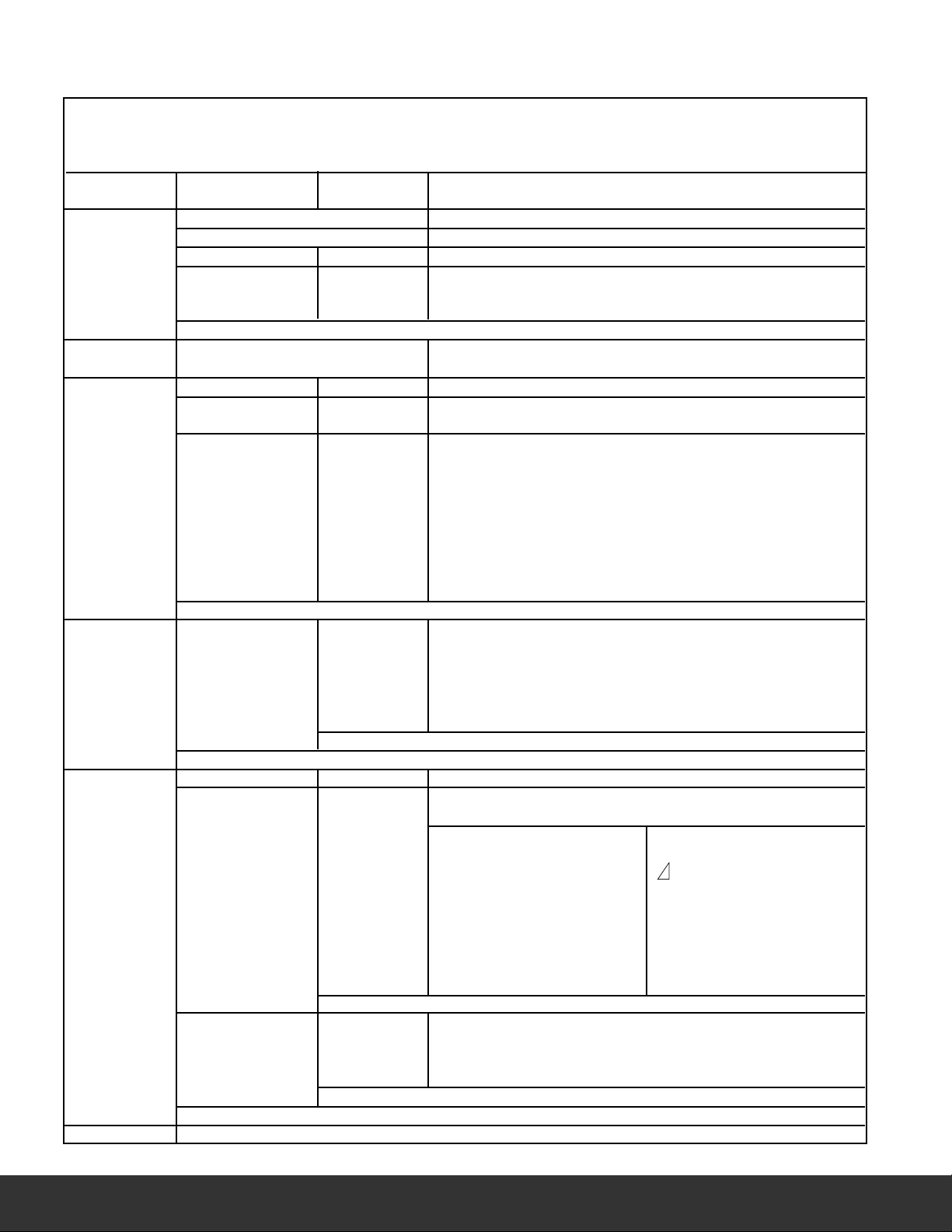
MAIN MENU NAVIGATION
Use the “s“UP or “t“DOWN buttons to scroll through the MAIN MENU or OPTIONS. Press “SEND” to select displayed
screen choice. NOTE: Rotate the selector off menu at any time to EXIT. Selections will NOT be saved unless you press “SEND”
PRESS “s“UP to scroll through menu items in this order.
press “
s“ press “s“
AIN MENU SUB MENU OPTIONS Notes
M
SETUP SET TIME Use to set current time.
SET DATE Use to set current date.
< - - -> F ˚F or ˚C Use to select temperature scale.
C
LANGUAGE ENGLISH Use to select language.
FRENCH
PANISH
S
EXIT Return to main menu.
GAS ZERO RESET GAS ZERO Press “SEND” to start.
(EagleX ONLY) Automatically returns to main menu.
PRESSURE SMOOTH ON/OFF Use to change screen update rate.
RESOLVE HIGH Use to select display resolution.
LOW
S UNITS Use to select desired unit of measure. Choose beetween:
P
In H2O inches H2O (water gauge)
mbar millibar
mmH2O millimeters of H2O
Pa Pascals
kPa Kilopascals
PSI Pounds per square inch
mmHg Millimeters of mercury
hPa Hecto pascals
EXIT Return to main menu.
REPORT COMB’N VIEW When viewing reports:
PRESSURE DEL ALL -Press “s“UP or “t“DOWN to select report #.
EXCH -Press and hold “
TEMP lines in VIEW.
ROOM CO -Press SEND to print current viewed report.
-Press and hold SEND to exit view.
EXIT Return to Sub Menu.
XIT Return to main menu.
E
N CONTRAST 00~20 Use to change screen contrast.
E
E
R
SC
AUX LINE 1 -Select parameter displayed for each line.
E 2
LIN
E 3
N
LI
LINE 4 CO Carbon Monoxide DATE (shows date)
XIT
E
HEADER HEADER1 Customize header information
ADER2 Screen shows (*OUR COMPANY NAME &_ _ _ _)
E
H
XIT
E
XIT
E
SERVICE Used by technicians to calibrate combustion gas sensors.
-Press “
s“UP to choose bet
∆T
P
X
Efn Efficiency CO2 Carbon Dioxide
NO
Oa
C
BAT Battery Level TF Flue Temp (T2)
D
-Press U
choose, press ENTER.
s“UP or “t“DOWN to change the displayed
ween:
E
emp differential TI
T
Pressure
Excess Air
NO
ree
O Air F
C
aft
Dr
P or DOWN to scroll through letters and symbols to
M
R
O2
TI
ws time)
(sho
osses
L
O/CO2 Ratio
C
Oxygen
emp (T1)
Inlet T
Return to Sub Menu.
Return to Sub Menu.
Return to main menu.
8
Page 9

WHAT RESULTS ARE GENERALLY ACCEPTABLE
ATMOSPHERIC GAS FIRED BURNERS
• Oxygen ....................................................................................... 7 to 9% O2
•
Stack Temperature ................................................................... 325 to 500°F
•
Draft (Water Column Inches).................................................... -.02 to -.04wc”
Carbon Monoxide (parts per million) ...................................... <100ppm
•
GAS FIRED POWER BURNERS
• Oxygen ....................................................................................... 3 to 6% O2
•
Stack Temperature ................................................................... 275 to 500°F
tack Draft (Water Column Inches).......................................... -.02 to -.04wc”
•
S
verfire Draft (Water Column Inches)..................................... -.02wc”
•
O
•
arbon Monoxide(parts per million) ...................................... <100ppm
C
REDBURNERS
OILFI
• Oxygen ....................................................................................... 4 to 7% O2
•
Stack Temperature ................................................................... 325 to 600°F
Stack Draft (Water Column Inches).......................................... -.04 to -.06wc”
•
•
Overfire Draft (Water Column Inches)..................................... -.02wc”
•
Carbon Monoxide (parts per million) ...................................... <100ppm
Smoke ........................................................................................ 0 (or manufacturer’s recommendation)
•
POSITIVE OV
NOTE: Follow manufacture guidelines for the specific equipment being serviced.
ERFIREGAS
• Oxygen ....................................................................................... 3 to 9% O2
•
Stack Draft (Water Column Inches).......................................... -.02 to -.04wc”
•
Overfire Draft (Water Column Inches)..................................... +0.4 to +0.6wc”
Carbon Monoxide (parts per million) ...................................... <100ppm
•
(#2 OILFUEL)
L
& OI
TYPICAL EXCESS AIR LEVEL
O2% (measured) Excess Air %
Natural gas 3% 16.7%
Light Oil 5% 31%
Coal 8% 62%
PROVIDE YOUR CUSTOMER FACTS, NOT OPINIONS.
Combustion Heat Exchanger Differential
Temperature
Manometer
Draft/Pressure
Room CO Auxiliary
(EagleX Only)
9
Page 10
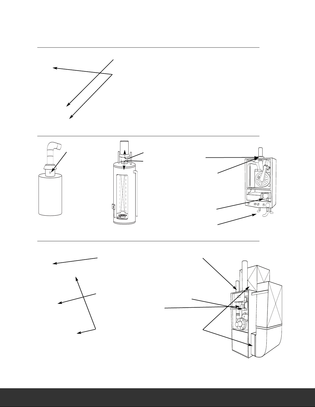
WHERE TO TEST
AIR CONDITIONING / HEAT PUMP
Suction Line:
• Temperature
Verify proper:
Static Duct Pressures
•
• Temperature Differential
• Static Pressure Drop Across Coils
to condensing unit
BOILER & WAT E R HEATERS & HIGH EFFICIENCY MODULATING HOT WAT ER SYSTEMS
I
BO
LER
Verify proper combustion:
• O2
• CO Air Free
• Stack Temp
• Stack Draft
• SSE
WATE R HEATER
Draft
Verify proper combustion:
• O2
• CO
• Stack Temp
• Efficiency
HE BO
ILERINSTANT
WATE R HEATERS
Draft
Verify proper
combustion:
• O2
• CO
• Stack Temp
• Efficiency
Hi / Low fire Gas
Pressure
Send and Return
Water temp
FURNACES: 80% FURNACES: 90%
NACE
0% F
R
8
U
Verify proper combustion:
• O2
• CO
• Stack Temp
• Vent Pressure
• Efficiency
erify/Set Up
V
• Gas Pressure
est
T
• Limit Switch
• Pressure Switch
Verify proper operation:
• Static Duct Pressur
emperature Rise
• T
• AC side Static Pressure
Dr
op acr
oss coils
0%+ F
9
Verify proper combustion:
erify/Set Up
V
est
T
Verify proper operation:
e
NACE
R
U
• O2
• CO
• Stack Temp
• Vent Pressure
• Efficiency
• Gas Pressure
• Limit Switch
• Pressure Switch
• Static Duct Pressur
emperature Rise
• T
• AC side Static Pressure
Dr
op acr
oss coils
e
10
Page 11
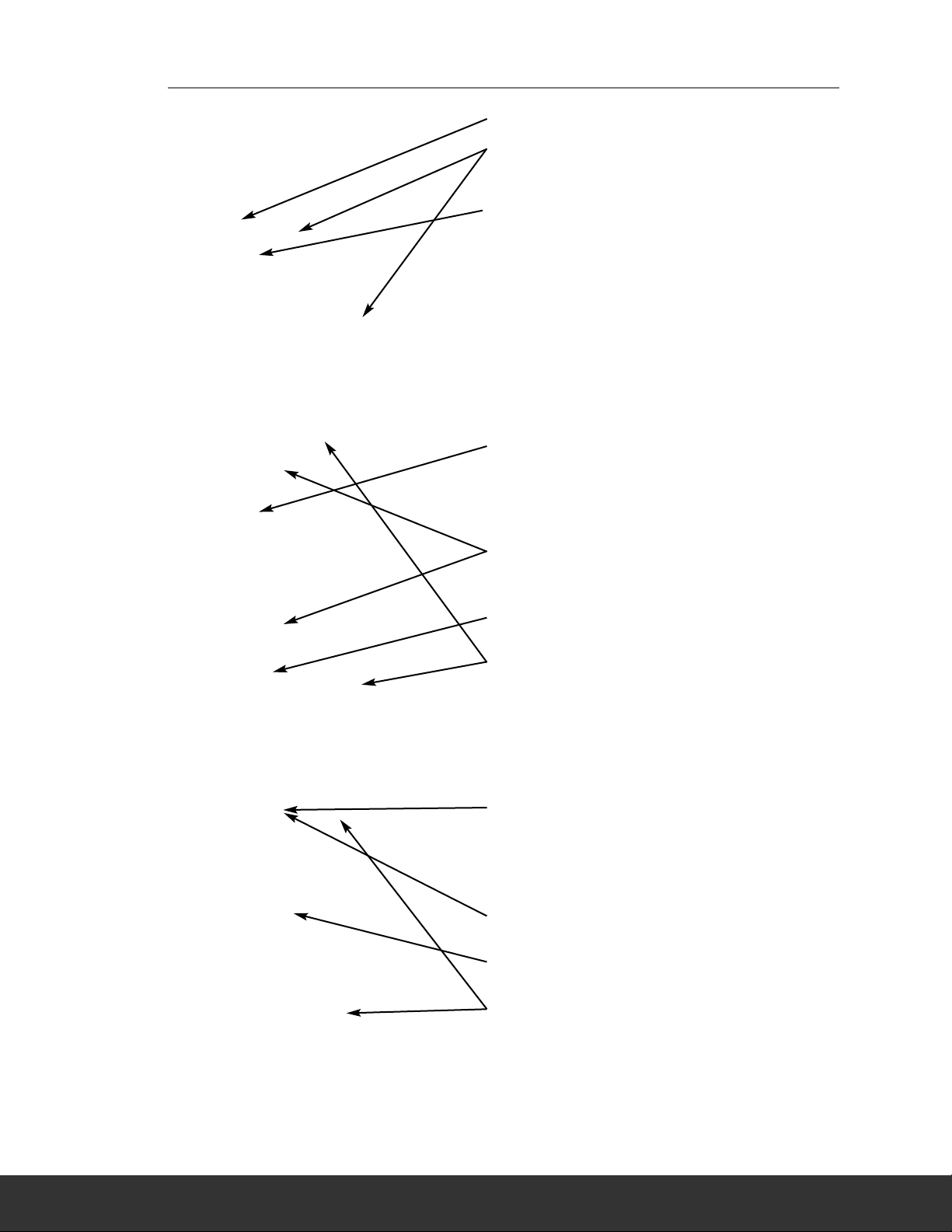
FURNACES (CONTINUED): ATMOSPHERIC, GAS & OIL
AT
MOSPHERICFURNACE
Draft
Verify proper
• Temperature Rise
•
Verify proper combustion:
• O2
• CO
• Stack Temp
• Efficiency
AC side Static Pressure Drop across coils
NA
TURALGAS
& PR
OPANE
Verify proper combustion:
• O2
• CO
• Stack Temp
• Vent Pressure
• Efficiency
Test
• Limit Switch
• Pressure Switch
Set Up
• Gas Pressure
Verify proper:
• Static Duct Pressure
• Temperature Rise
• AC side Static Pressure Drop across coils
OIL FURNACE
oper combustion:
erify pr
V
• O2
• CO
emp
• Stack T
• Stack Draft
• Efficiency
Test & Verify:
• Smoke
Set Up
• Over Fire Draft
oper
erify pr
V
• Static Duct Pressure
• Temperature Rise
• AC side Static Pressure Drop across coils
11
Page 12

OTHER IMPORTANT FACTORS RELATING TO COMBUSTION
• The three T’s of combustion
– Time
• Amount of time that the fuel and oxygen are together in the combustion chamber
Temperature
–
• How high the temperature is determines the rate of oxidation, or speed of the combustion
– Turbulence
• How well the fuel and air are mixed
These three factors are all interrelated, and will move your results along the combustion curves.
•
COMBUSTION MEASUREMENT TERMS
Other parameters measured include net temperature, draft and efficiency.
Net Temperature
Net temperature is the difference between the combustion air entering the combustion chamber and the flue gas temperature past
the heat exchange. This is used to determine how efficient the system is extracting heat from the combustion process in addition to
the performance of the combustion process. On sealed systems that have ducted inlet air for combustion air, the net temperature
must compare this air stream temperature with the flue gases. If the appliance simply uses room air for the combustion air, our
analyzers have an internal temperature sensor in the handset, so it will use this temperature when calculating net temperature.
The most accurate results for efficiency are obtained when measuring flue gases at the point where flue temperature (not flame temperature) is the highest.
Draft
Draft is the difference between the ambient pressure level and the pressure level in the flue. This is created either by the natural
buoyancy of the hot gases created in combustion lifting, or by an inducer fan that assists the flow of flue gases up the stack. Most
combustion equipment will specify the amount of draft that is required for proper operation.
Draft helps draw combustion air into the combustion chamber, and also helps in mixing the fuel and oxygen. Without proper
draft, the combustion process can spill poisonous by-products into the space where the appliance is located. This can be a risk to
those in the area, or create a danger to residents or employees working near the combustion equipment.
Efficiency
Efficiency is a measure of how well the fuel is burned to create heat, and how well the generated heat is captured for the intended
use.
The information used to create this value are based on the fuels heating value, the heat lost up the flue and the gas components in
the flue gas. The original method to determine efficiency included many manual methods and lookup charts. As an example you
would measure the CO2 level and the stack temperature and then reference a slide scale that would give you the relative efficiency
number. UEi’s electronic combustion analyzers perform the measurements on a continuous basis, and can calculate the efficiency
as adjustments are being made. Combine this with a printout and you are able to provide a before and after comparison of the
combustion equipment in relatively little time as part of normal servicing.
12
Page 13

CO AIR FREE
Certain standards ( ANSI Z21.1) for Carbon Monoxide are stated in terms of air-free. Air-free refers to the concentration of CO in combustion gases undiluted with flue, or other gases containing little CO. This value is computed using an equation that takes into account the O2 concentration of the flue gas.
• If 5% O2 is measured (O2m) in the flue then the CO gas value will be recalculated as if 0% were measured.
he equation for air-free is as follows:
T
COaf = CO PPM x [(20.9) / (20.9 - O2m)]
In our example if a reading of 325 PPM were measured then the air-free value would be calculated as follows:
•
- COaf = 325 PPM x [(20.9) / (20.9 - 5)] COaf = 325 PPM x [(20.9) / (15.9)] COaf = 427
We may be given a limit on our gas range by the local authority, which stated that we must not emit more than
400-PPM Carbon Monoxide air-free. In the example we would be breaking the limit and corrective action should be
taken to reduce the level of CO. Air-free values prevent false readings being submitted, e.g. allowing more air into the
boiler will increase the oxygen level in the flue and dilute any toxic gas reading. Air-free referencing gives readings as if
they were undiluted.
COMBUSTION EFFICIENCY CALCULATIONS
This identifies three sources of loss associated with fuel burning:
• Losses due to flue gasses:
- Dry Flue gas loss, Moisture and hydrogen,
- Sensible heat of water vapor, Unburned gas
• Losses due to refuse:
- Combustible in ash, riddling and dust
• Other losses:
- Radiation, convection, conduction other unmeasured losses
combustion and from wet fuel) is recovered and the wet loss term is zero. Gross efficiency calculations assume that the
energy contained in the water vapor is not recovered. Since the fuel air mixture is never consistent there is the possibility of unburned/partially unburned fuel passing through the flue. This is represented by the unburned carbon loss.
Losses due to combustible matter in ashes, riddling, dust and grit, radiation, convection and conduction are not
included.
Efficiency Calculation:
• Known Data Fuel:
• Known Data Value:
• Measured Data:
• Calculated data:
• Tnet = Flue Temperature - Inlet Temperature (or ambient)
• D
• Wet loss %
• Simplified
Net efficiency calculations assume that the energy contained in the water vapor (formed as a product of
- Qgr = Gross Calorific Value (kJ/kg)
- Qnet = Net Calorific Value (kJ/kg)
- K1 = Constant based on Gross or Net Calorific • •
- K1g = ( 255 x %Carbon in fuel )/Qgr
- K1n = ( 255 x %Carbon in fuel )/Qnet
- K2 = % max theoretical CO2 (dry basis)
- K3 = % Wet Loss
- H2 = % Hydrogen
- H2O = % Water
-Tf = Flue Temperature
-Ti = Inlet Temperature
-O2m = % Oxygen in flue gas
-O2r = Oxygen r
- Tnet = Net Temperature
- % CO2 content in flue gas
-% Dry Flue Gas losses
-% Wet losses
-% Unburned carbon loss
-% Efficiency
y flue gas loss %
r
= 20.9 x K1 x (Tnet) / K2 x (20.9 - O2m)
= 9 x H2 + H2O / Qgr x [2488 + 2.1Tf - 4.2 Ti]
= [(9 x H2 + H2O) / Qgr] x 2425 x [1 + 0.001 Tnet]
efer
ence %
• Wet loss %
= K3(1+0.001xTnet)
• Where K3
= [(9 x H2 + H2O) / Qgr] x 2425
• Net Efficiency %
= 100 - dry flue gas losses
= 100 - 20.9 x K1n x (Tnet) / K2 x (20.9 -O2m)
• Gross Efficiency %
= 100 - {dry flue gas losses + wet losses}
= 100 – {[20.9 x K1g x (Tnet) / K2 x (20.9 - O2m)]+
[K3 x (1 + 0.001 x Tnet)]}
• Excess Air
= [20.9 / (20.9 - O2m) - 1] x 100
• CO2%
= [(20.9 - O2m) x K2 / 20.9]
nburned
• U
= K4 x CO / ( CO + CO2 )
Note: CO scaled in % fuel Loss %
• Where K4
= 70 for coke
= 65 for anthracite
= 63 for Bituminous coal
= 62 for coal tar fuel
= 48 for liquid petroleum fuel
= 32 for natural gas
The formula for K4 is based on the gross calorific value
Qgr. To obtain the loss based on net calorific value multiply by Qgr/Qnet. Since this loss is usually small this conversion has been ignored. This loss is subtracted from the
efficiency.
13
Page 14

GENERAL MAINTENANCE
• Calibrate your instrument annually to ensure it meets original performance specifications
Keep your instrument dry. If it gets wet, wipe dry immediately. Liquids can degrade electronic circuits
•
• Whenever practical, keep the instrument away from dust and dirt that can cause premature wear
• Although your instrument is built to withstand the rigors of daily use, it can be damaged by severe
impacts. Use reasonable caution when using and storing the meter
PERIODIC SERVICE
WARNING!
Repair and service of this instrument is to be performed by qualified personnel only. Improper repair or
service could result in physical degradation of the instrument. This could alter the protection from personal
injury this meter provides to the operator. Perform only those maintenance tasks that you are qualified to do.
ANNUAL RE-CALIBRATION
While the sensor has an expected life of more than two years in normal use it is recommended that the
analyzer is re-calibrated at least annually, This is so that long-term drift on the sensor and electronics can be
eliminated. Local regulations may require more frequent re-calibration and users should check with
appropriate authorities to ensure they comply with relevant guidelines.
CLEANING
GENERAL MAINTENANCE
Periodically clean your instruments case using a damp cloth. DO NOT use abrasive, flammable liquids,
cleaning solvents, or strong detergents as they may damage the finish, impair safety, or effect the reliability
of the structural components.
EMPTYING & CLEANING THE IN-LINE WATER TRAP
The in-line water trap should be checked and emptied on a regular basis. Water vapor will condense in the
probe line, which may cause the water trap to fill suddenly if the probe is moved. Care should be taken
at all times.
Carefully remove the rubber plug from the bottom
of the water-trap housing. Dispose of the condensate in
a suitable drain, care must be taken as it could be acidic.
If condensate spills onto the skin or clothing, clean off
, seek medical advice
lug is not in place.
rap P
R
TE
L
FI
face.
e the filter and plastic
v
iscard the filter
it the holder onto
.
er
CH
TI
e. R
ater
C
emo
esh water
T
LE
immediately using fr
if problems occur. Ensure plug is replaced before
performing combustion tests. Note: O2 reading will
be high if the W
ING
G
AN
THEPAR
This is a very important part of the analyzer and should be changed regularly. It prevents dust and dirt
particles from entering the pump and sensors that will cause damage. The filter MUST be changed when
it appears discolored on the inner sur
Remove water-trap assembly from the analyzer
as shown abov
holder from the housing. D
element but keep the holder to fit to the new
filter. Clean the inside of the filter housing
with a suitable soft cloth. F
the new filter element and then insert into the
housing. R
efit the housing onto the analyz
Hook slides
out of dock
Slide outward
Pull plug out
to drain
Insert a new filter
14
Page 15

BATTERIES REPLACEMENT
This meter has been designed for use with both alkaline
and rechargeable Nickel Metal Hydride (NiMH) batteries.
No other types are recommended. The analyzer is supplied
ith 4 “AA” size alkaline batteries.
w
These should be installed into the instrument as shown
in the diagram to the right and indicated on the back of
the unit.
CAUTION!
Take great care when installing the batteries to observe
correct polarity. Always check the meter for operation
immediately after installing new batteries.
USING RE-CHARGEABLE BATTERIES
The battery charger must only be used when NiMH batteries are fitted. Alkaline batteries are not
re-chargeable. Attempting to recharge alkaline batteries may result in damage to the product and may
create a fire risk.
BAT TE RY CHARGING
Ensure that you use the correct charger. This unit uses a 9V DC regulated charger.
Ensure that the batteries are fitted in the correct manner, and then charge for at least 16 hours. Subsequent
charges should be overnight. NiMH batteries may be charged at any time, even for short periods to
conduct testing.
Back of
Instrument
Note: Follow battery
d
irections on back of
h
ousing
C75 Directions
Battery Compartment
C125/C127, C155/C157
Directions
OR
Cover
WARNING!
Under NO circumstance should you expose batteries to extreme heat or fire as they may explode and cause
injury. Always dispose of old batteries promptly in a manner consistent with local disposal regulations.
ELECTROMAGNETIC COMPATIBILITY (EMC)
This product has been tested for compliance with the following generic standards:
EN 50081-1, EN 50082-1 and is certified to be compliant.
opean Council Directive 89/336/EEC requires that electronic equipment does not generate
ur
The E
electromagnetic disturbances that exceed defined levels and has an adequate level of immunity to enable it to
be operated as intended.
Since there are many electrical products in use that pre-date this Directive and may emit electromagnetic
radiation in excess of the standards defined in the Directive there may be occasions where it would be
opriate to check the analyz
appr
• Go through the normal start up sequence in the location where the equipment is to be used
witch on all localized electrical equipment that might be capable of causing interference
• S
• Check that all readings are as expected (a level of disturbance in the readings is acceptable)
• If not, adjust the position of the instrument to minimize interference or switch off, if possible, the
offending equipment for the duration of the test
t the time of writing this manual (
A
ference has ever occurred and this advice is only given to satisfy the requirements of the Directive.
inter
er prior to use. The following procedure should be adopted.
uly 2009) UE
J
i is not awar
e of any field based situation where such
15
Page 16

EAGLE SPECIFICATIONS
C125 C127 C155 C157
Temperature Measurement
Flue Temp Range 20~2400˚F (-29~1315˚C)
nlet Temperature (probe - T2) 20~2400˚F (-29~1315˚C)
I
Inlet Temperature (ambient) 32~112˚F (0~50˚C)
Net Temperature (_T)** 20~2400˚F (-29~1315˚C)
esolution 0.1˚C/F
R
Flue (T1, Inlet T2 & _T) Accuracy ±(0.3% rdg +3.6˚F(2˚C))
Inlet Temperature Accuracy ±(0.3% rdg +1.8˚F(1˚C))
Gas Measurement
Oxygen 0~21%* 0~21%* 0~21%** 0~21%**
2 resolution / accuracy 0.1% / ±0.2% 0.1% / ±0.2% 0.1% / ±0.3% 0.1% / ±0.3%
O
Carbon Monoxide (CO) 0~2000 ppm (4000 max 15 min)*
CO resolution / accuracy 1ppm/ ±10ppm<100ppm
±5% rdg>100ppm
Carbon Dioxide (CO2) 0~30%** 0~30%** 0~20%* 0~20%*
CO2 resolution / accuracy 0.1% / ±3% 0.1% / ±3% 0.1% / ±2% 0.1% / ±2%
Efficiency** 0~99.9%** 0~99.9%** 0~99.9%** 0~99.9%**
Efficiency resolution/accuracy 0.1% / ±3% 0.1% / ±3% 0.1% / ±3% 0.1% / ±3%
Excess Air** 0~250%** 0~250%** 0~250%** 0~250%**
Excess Air resolution/accuracy 0.1% / ±3% 0.1% / ±3% 0.1% / ±3% 0.1% / ±3%
CO/CO2 ratio** 0~0.999 0~0.999 0~0.999 0~0.999
CO/CO2 resolution/accuracy 0.001 / ± 5% rdg 0.001 / ± 5% rdg 0.001 / ± 5% rdg 0.001 / ± 5% rdg
Nitric Oxide (NO1) - -0~100 ppm - 0~100 ppm
NO1 resolution/accuracy - ±2 ppm<30ppm - ±2 ppm<30ppm
- ±5 ppm<100 ppm - ±5ppm<100 ppm
Pressure (Differential) Range Accuracy
±0.08” wc (±0.2mBar) ±0.002” wc (±0.005mBar)
±0.4” wc (±1mBar) ±0.01” wc (±0.03mBar)
±32” wc (±80mBar) ±3% rdg
Pressure Resolution 0.001” wc < 9.999” wg
0.01” wc >10.00” wg
0.001mBar<24.999mBar
0.01mBar > 25 mBar
* Measured at STP (standard temperature and pressure)
** Calculated value
EAGLE & EAGLE X LIMITED WARRANTY
The Eagle Combustion Analyzers (C75, C125, C127) are warrantied to be free from defects in materials and workmanship for a period of
thr
ears (two y
ee y
ears on sensors) fr
If within the warranty period your instrument should become inoperative from such defects, the unit will be repaired or replaced at UEi’s
This warranty cov
option.
ers normal use and does not cover damage which occurs in shipment or failure which results from alteration,
tampering, accident, misuse, abuse, neglect or improper maintenance (calibration). Batteries and consequential damage resulting from failed
y warranty
ed b
batteries are not cov
er
Any implied warranties, including but not limited to implied warranties of merchantability and fitness for a particular purpose, are limited
to the expr
ess warranty. UEi shall not be liable for loss of use of the instr
economic loss, or for any claim or claims for such damage, expenses or economic loss. A purchase receipt or other proof of original purchase
date will be required before warranty repairs will be rendered. Instruments out of warranty will be repaired (when repairable) for a service
charge. Contact UE
i for specific warranty and ser
rights which vary from state to state.
om the date of purchase. Eagle X (C155, C157) are each warrantied for five years including sensors.
.
ument or other incidental or consequential damages, expenses, or
vice information.
This warranty giv
ou specific legal rights.
es y
You may also have other
USA: 1.800.547.5740 • Fax: 503.643.6322
CANADA: 1-877-475-0648 • Fax: 604.278.8299
WWW.UEiTEST.COM
COPYRIGHT © 2009 UEi. EAGLE Combustion Analyzers™ is a trademark of UEi. PRIN109/3k 10/09 18323
 Loading...