

Page 1
UTG1000A Series Function Generator User Manual
0
Page 2

UTG1000A Series Function Generator User Manual
Preface
Dear Users:
Hello! Thank you for choosing this brand new Uni-Trend device. In order to use this instrument safely
and correctly, please read this manual thoroughly, especially the Safety Notes part.
After reading this manual, it is recommended to keep the manual at an easily accessible place,
preferably close to the device, for future reference.
1
Page 3

UTG1000A Series Function Generator User Manual
Copyright Information
UNl-T is Uni-Trend Technology (China) Limited. All rights reserved.
UNI-T products are protected by patent rights in China and other countries, including issued and
pending patents.
Uni-Trend reserves the rights to any product specification and pricing changes.
Uni-Trend reserves all rights. Licensed software products are properties of Uni-Trend and its
subsidiaries or suppliers, which are protected by national copyright laws and international treaty
provisions. Information in this manual supercedes all previously published versions.
UNI-T is the registered trademark of Uni-Trend Technology (China) Limited.
Uni-Trend warrants that this product will be free from defects for a three-year period. If the product is
re-sold, the warranty period will be from the date of the original purchase from an authorized UNI-T
distributor. Probes, other accessories, and fuses are not included in this warranty.
If the product is proved to be defective within the warranty period, Uni-Trend reserves the rights to
either repair the defective product without charging any parts or labor, or exchange the defected
product to a working equivalent product. Replacement parts and products may be brand new, or
perform at the same specifications as brand new products. All replacement parts, modules, and
products are the property of Uni-Trend.
The “customer” refers to the individual or entity that is declared in the guarantee. In order to obtain
the warranty service, "customer" must inform the defects within the applicable warranty period to
UNI-T, and to perform appropriate arrangements for the warranty service. The customer shall be
responsible for packing and shipping the defective products to the designated maintenance center of
UNI-T, pay the shipping cost, and provide a copy of the purchase receipt of the original purchaser. If the
product is shipped domestically to the location of the UNI-T service center, UNI-T shall pay the return
shipping fee. If the product is sent to any other location, the customer shall be responsible for all
shipping, duties, taxes, and any other expenses.
This warranty shall not apply to any defects or damages caused by accidental, machine parts’ wear and
tear, improper use, and improper or lack of maintenance. UNI-T under the provisions of this warranty
has no obligation to provide the following services:
a) Any repair damage caused by the installation, repair, or maintenance of the product by non UNI-T
service representatives.
b) Any repair damage caused by improper use or connection to an incompatible device.
c) Any damage or malfunction caused by the use of a power source which does not conform to the
requirements of this manual.
2
Page 4

UTG1000A Series Function Generator User Manual
d) Any maintenance on altered or integrated products (if such alteration or integration leads to an
increase in time or difficulty of product maintenance).
This warranty written by UNI-T for this product, and it is used to substitute any other expressed or
implied warranties. UNI-T and its distributors do not offer any implied warranties for merchantability or
applicability purposes.
For violation of this guarantee, UNI-T is responsible for the repair or replacement of defective products
is the only remedy available to customers. Regardless of whether UNI-T and its distributors are
informed that any indirect, special, incidental, or consequential damage may occur, the UNI-T and its
distributors shall not be responsible for any of the damages.
Warranty
UNI-T warrants that the product will be free from defects for a three-year period. If the product is
re-sold, the warranty period will be from the date of the original purchase from an authorized UNI-T
distributor. Probes, other accessories, and fuses are not included in this warranty.
If the product is proved to be defective within the warrenty period, UNI-T reserves the rights to either
repair the defective product without charging of parts and labor, or exchange the defected product to a
working equivalent product. Replacement parts and products may be brand new, or perform at the
same specifications as brand new products. All replacement parts, modules, and products become the
property of UNI-T.
The “customer” refers to theindividual or entity that is declared in the guarantee. In order to obtain the
warranty service, "customer" must inform the defects within the applicable warranty period to UNI-T,
and to perform appropriate arrangements for the warranty service. The customer shall be responsible
for packing and shipping the defective products to the designated maintenance center of UNI-T, pay
the shipping cost, and provide a copy of the purchase receipt of the original purchaser. If the product is
shipped domestically to the location of the UNI-T service center, UNI-T shall pay the return shipping fee.
If the product is sent to any other location, the customer shall be responsible for all shipping, duties,
taxes, and any other expenses.
This warranty shall not apply to any defects or damages caused by acciendental, machine parts’ wear
and tear, improper use, and improper or lack of maintenance. UNI-T under the provisions of this
warranty has no obligation to provide the following services:
a) Any repair damage caused by the installation, repair, or maintenance of the product by non UNI-T
service representatives.
b) Any repair damage caused by improper use or connection to an incompatible device.
c) Any damage or malfunction caused by the use of a power source which does not conform to the
requirements of this manual.
3
Page 5

UTG1000A Series Function Generator User Manual
d) Any maintenance on altered or integrated products (if such alteration or integration leads to an
increase in time or difficulty of product maintenance).
This warranty written by UNI-T for this product, and it is used to substitute any other express or implied
warranties. UNI-T and its distributors do not offer any implied warranties for merchatability or
applicability purposes.
For violation of this guarantee, UNI-T is responsible for the repair or replacement of defective products
is the only remedy available to customers. Regardless of whether UNI-T and its distributors are
informed that any indirect, special, incidental, or consequential damage may occur, the UNI-T and its
distributors shall not be responsible for any of the damages.
General Safety Overview
This instrument strictly complies with the safety requirements for electronic measuring instrument
GB4793 and IEC 61010-1 safety standard during design and manufacturing. Please understand the
following safety preventative measures, to avoid personal injury, and to prevent damage to the product
or any connected products. To avoid possible dangers, be sure to use this product in accordance with
the regulations.
Only trained personnels can perform the maintenance program.
Avoid fire and personal injury.
Use the correct power line: Only use the dedicated UNI-T power supply appointed to the local region
or country for this product.
Correct Plug: Don't plug when the probe or test wire is connected to the voltage source.
Ground the product: This product is grounded through the power supply ground wire. To avoid electric
shock, grounding conductors must be connected to the ground. Please be sure that the product is
properly grounded before connecting to the input or output of the product.
Correct connection of oscilloscope probe: Ensure that the probe ground and ground potential are
correctly connected. Do not connect ground wire to high voltage.
Check all terminal ratings: To avoid fire and the large current charge, please check all the ratings and
the marks on the product. Please also refer to the product manual for details on the ratings before
connecting to the product.
Do not open the case cover or front panel during operation
Only use fuses with ratings listed in the technical index
Avoid circuit exposure: Do not touch exposed connectors and components after power is connected.
4
Page 6
UTG1000A Series Function Generator User Manual
Do not operate the product if you suspect it is faulty, and please contact UNI-T authorized service
personnel for inspection. Any maintenance, adjustment, or replacement of parts must be performed by
UNI-T authorized maintenance personnels.
Maintain proper ventilation
Please do not operate the product in humid conditions
Please do not operate in inflammable and explosive environment
Please keep the product surface clean and dry
Safety Terms and Symbols
The following terms may appear in this manual:
Warning: The conditions and behaviors may endanger life.
Note: The conditions and behaviors may cause damage to the product and other properties.
The following terms may appear on the product:
Danger: Performing this operation may cause immediate damage to the operator.
Warning: This operation may cause potential damage to the operator.
Note: This operation may cause damage to the product and devices connected to the product.
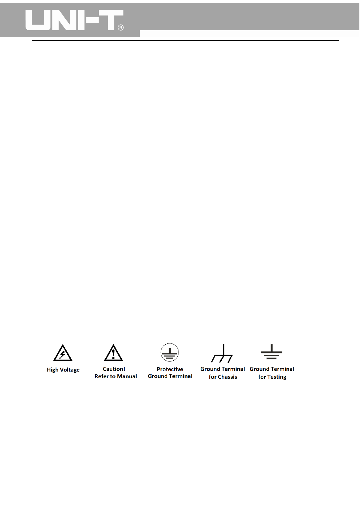
The following symbols may appear on the product:
5
Page 7

UTG1000A Series Function Generator User Manual
Table of Contents
Preface ............................................................................................................................................. 1
Copyright Information ....................................................................................................................... 2
Warranty .......................................................................................................................................... 3
General Safety Overview ................................................................................................................... 4
Safety Terms and Symbols................................................................................................................. 5
Table of Contents .............................................................................................................................. 6
Chapter 1 Introduction ...................................................................................................................... 8
1.1 Safety Terms and Symbols ..................................................................................................... 8
1.2 General Safety Overview ....................................................................................................... 9
Chapter 2 Introduction .................................................................................................................... 10
2.1 Main Features .............................................................................................................................. 10
2.2 Panels and Buttons ...................................................................................................................... 10
2.2.1 Front Panel ........................................................................................................................ 10
Chapter 3 Quick Start ...................................................................................................................... 15
3.1 General Inspection ...................................................................................................................... 15
3.1.1 Check for Damages Caused by Transport ......................................................................... 15
3.1.2 Check Accessories ............................................................................................................. 15
3.1.3 Machine Inspection ........................................................................................................... 15
3.2 Handle Adjustment ..................................................................................................................... 15
3.3 Basic Waveform Output .............................................................................................................. 16
3.3.1 Frequency Setting ............................................................................................................. 16
3.3.2 Amplitude Setting ............................................................................................................. 16
3.3.3 DC Offset Voltage Setting .............................................................................................. 17
3.3.4 Square Wave Setting ...................................................................................................... 18
3.3.5 Pulse Wave Setting ........................................................................................................ 18
3.3.6 DC Voltage Setting ......................................................................................................... 19
3.3.7 Ramp Wave Setting ........................................................................................................ 20
3.3.8 Noise Wave Setting ........................................................................................................ 20
3.4 Frequency Measurement ............................................................................................................ 21
3.5 Build-in Help System ................................................................................................................... 21
Chapter 4 Advanced Applications 4.1 ROLL mode ............................................................................ 22
4.1 Modulation Waveform Output ................................................................................................... 22
4.1.1 Amplitude Modulation (AM) ............................................................................................. 22
4.1.2 Frequency Modulation (FM) ............................................................................................. 29
4.1.3 Phase Modulation (PM) .................................................................................................... 37
4.1.4 Amplitude Shift Keying (ASK) ............................................................................................ 44
4.1.5 Frequency Shift Keying (FSK) ............................................................................................ 50
4.1.6 Phase Shift Keying (PSK) .................................................................................................... 57
6
Page 8

UTG1000A Series Function Generator User Manual
4.1.7 Pulse Width Modulation (PWM) ....................................................................................... 64
4.2 Sweep Waveform Output ........................................................................................................... 71
4.2.1 Sweep Selection ................................................................................................................ 71
4.2.2 Start Frequency and Stop Frequency Setting ................................................................... 72
4.2.3 Sweep Mode ..................................................................................................................... 74
4.2.4 Sweep Time ....................................................................................................................... 74
4.2.5 Trigger Source Selection ................................................................................................... 74
4.2.6 Trigger Output ................................................................................................................... 75
4.2.7 Comprehensive Example .................................................................................................. 75
4.3 Arbitrary Wave Output ............................................................................................................... 79
4.3.1 Enable Arbitrary Wave Function ....................................................................................... 79
4.3.2 Arbitrary Wave Selection .................................................................................................. 80
Chapter 5 Trouble Shooting ............................................................................................................. 81
5.1 No Display On Screen (Black Screen) .......................................................................................... 81
5.2 No Waveform Output ................................................................................................................. 81
Chapter 6 Services and Supports ..................................................................................................... 82
6.1 Warranty Overview ..................................................................................................................... 82
6.2 Contact Us .................................................................................................................................... 82
Appendix A Factory Reset State ....................................................................................................... 83
Appendix B Technical Specifications ................................................................................................ 86
Appendix C Accessories List ............................................................................................................. 92
Appendix D Maintenance and Cleaning ........................................................................................... 93
7
Page 9
UTG1000A Series Function Generator User Manual
Chapter 1 Introduction
1.1 Safety Terms and Symbols
The following terms may appear in this manual:
Warning: The conditions and behaviors may endanger life.
Note: The conditions and behaviors may cause damage to the product and other properties.
The following terms may appear on the product:
Danger: Performing this operation may cause immediate damage to the operator.
Warning: This operation may cause potential damage to the operator.
Note: This operation may cause damage to the product and devices connected to the product.
Symbols on the product.
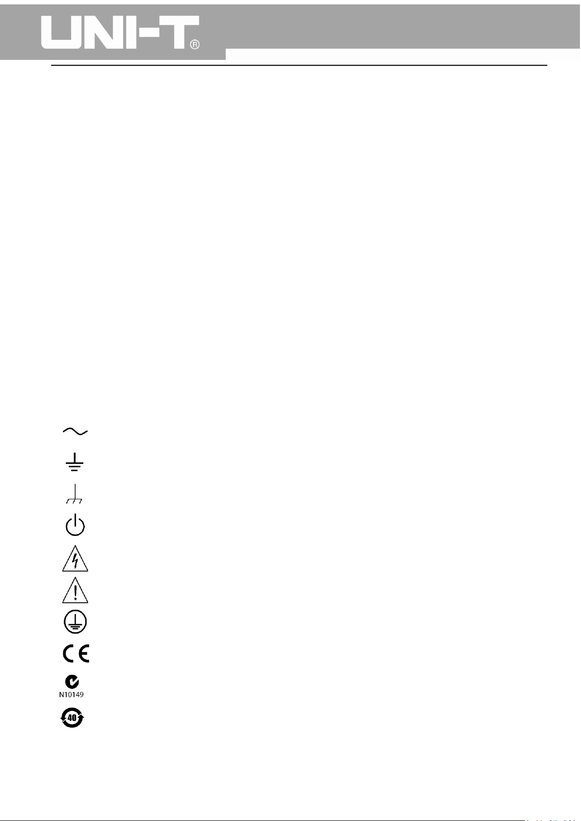
The following symbols may appear on the product:
Alternating Current
Ground Terminal for Testing
Ground Terminal for Chassis
On/Off Button
High Voltage
Caution! Refer to Manual
Protective Ground Terminal
CE logo is a registered trademark of the European Union.
C-tick logo is a registered trademark of Australia.
Environmental Protection Use Period (EPUP)
8
Page 10

UTG1000A Series Function Generator User Manual
1.2 General Safety Overview
This instrument strictly complies with the GB4793 safety requirements for electrical equipment and
EN61010-1/2 safety standard during design and manufacturing. It complies with the safety standards
for insulated voltage standard CAT II 300V and contamination level II.
Please read the following safety preventative measures:
To avoid electric shock and fire, please use the dedicated UNI-T power supply appointed to the local
region or country for this product.
This product is grounded through the power supply ground wire. To avoid electric shock, grounding
conductors must be connected to the ground. Please be sure that the product is properly grounded
before connecting to the input or output of the product.
To avoid personal injury and prevent damaging the product, only trained personnel can perform the
maintenance program.
To avoid fire or electric shock, please notice rated operating range and product marks. Do not use the
product outside the rated range.
Please check the accessories for any mechanical damage before usage.
Only use accessories that came with this product.
Please do not put metal objects into the input and output terminals of this product.
Do not operate the product if you suspect it is faulty, and please contact UNI-T authorized service
personnel for inspection.
Please do not operate the product when the instrument box opens.
Please do not operate the product in humid conditions.
Please keep the product surface clean and dry.
If the equipment is used in a manner not specified by the manufacturer, the protection provided by the
equipment may be impaired.
9
Page 11

UTG1000A Series Function Generator User Manual
Chapter 2 Introduction
This device is economical, high-performance, multi-functional single channel waveform generators. It
uses direct digital synthesis (DDS) technology to produce accurate and stable waveforms, with a
resolution as low as 1μHz. It can generate accurate, stable, pure and low distortion output signals, also
can provide high-frequency vertical edge square waves. UTG1000’s convenient interface, superior
technical indexes and user-friendly graphical display style can help users to complete tasks quickly and
improve work efficiency.
2.1 Main Features
Sine wave output of 20MHz/10MHz/5MHz, full frequency range resolution is 1μHz
Square wave/pulse waveform of 5MHz, and its rising, falling, and duty cycle time are adjustable
Using DDS implementation method, with 125M/s sampling rate and 14bits vertical resolution
6-bit high precision frequency counter that is TTL level compatible
Arbitrary waveform storage of 2048 points, and it can store up to 16 groups of nonvolatile
digital arbitrary waveforms
Abundant modulation types: AM, FM, PM, ASK, FSK, PSK, PWM
Powerful PC software
4.3-inch high resolution TFT liquid crystal display
Standard configuration interface: USB Device
Supports internal/external modulation and internal/external/manual trigger
Supports sweep output
Easy-to-use multifunctional knob and number keyboard
2.2 Panels and Buttons
2.2.1 Front Panel
UTG1000A series provides users with a simple, intuitive, and easy to operate front panel. The front
panel is shown in figure 2-1:
10
Page 12
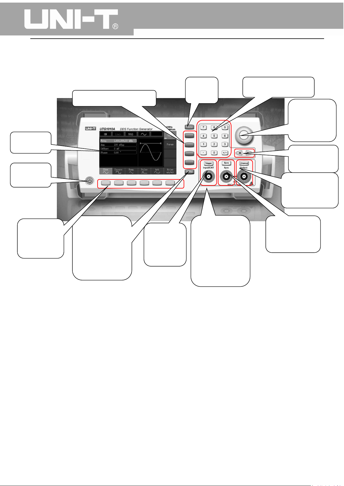
2.On/Off
Button
1.Display
Button
4. Auxiliary
Terminal
Terminal
5.Manual
Buttons
13.Function Menu Softkeys
3.Menu
Softkeys
UTG1000A Series Function Generator User Manual
Operation
Function and
System
Settings
Buttons
Trigger
Button
12.Menu
6. Modulation/
Frequency
Meter Input
Terminal/
Trigger Output
11. Number Buttons
Knob and
Button
9.Directional
8.CH Control/
Output Terminal
7. Synchronous
Output
1. Display Screen
4.3-inch TFT LCD displays high-resolution output state, function menu, and other important channel
information. It is designed to make human-computer interaction more convenient to improve work
efficiency.
2. On/Off Button
To turn on/off the device, press this button and its backlight will turn on (orange), the display will show
the function interface after the boot screen.
3. Menu Operation Softkeys
Correspondingly select or check the label contents by identifications of softkey labels (at the bottom of
function interface).
Figure 2-1
11
Page 13

UTG1000A Series Function Generator User Manual
4. Auxiliary Function and System Settings Button
This button includes 3 function labels: Channel settings, frequency meter, and system. A highlighted
label (the midpoint of the label is gray and font is pure white) has a corresponding sub label at the
bottom of the display.
5. Manual Trigger Button
Setting trigger, and carrying out manual trigger when flashing.
6. Modulation/Frequency Meter Input Terminal/Trigger Output Terminal
During AM, FM, PM or PWM signal modulation, when modulation source is external, modulation signal
is input through external modulation input. When frequency meter function is on, the signal to be
measured is input through this interface; when manual trigger for channel signal is enabled, manual
trigger signal is output through this interface.
7. Synchronous Output Terminal
This button controls whether open synchronous output or not.
8. CH Control/ Output
Channel output can be turned on/off quickly by pressing Channel button, also can be set by pressing
Utility button to pop-up the label, then pressing the Channel Setting softkey.
9. Direction Buttons
When setting parameters, move left and right to change number bit.
10. Multifunctional Knob and Button
Rotate the multifunctional knob to change numbers (rotate clockwise and numbers increase) or use the
multifunctional knob as direction button. Press the multifunctional knob to select function, set
parameters and confirm selection.
11. Number Keyboard
Number keyboard is used to enter parameter number 0 to 9, decimal point “.” and symbol key “+/-”.
Decimal point can change units quickly.
12. Menu Button
3 function labels will pop up by pressing the menu button: Waveform, Modulation, and Sweep. Press
the corresponding menu function softkey to get its function.
13. Functional Menu Softkeys
To select function menu quickly
12
Page 14

The rear panel is shown in figure 2-2:
UTG1000A Series Function Generator User Manual
Figure 2-2
1. USB Interface
PC software is connected through this USB interface.
2. Heat Dissipation Holes
To ensure this instrument dissipate heat well, please do not block these holes.
3. Insurance Pipe
When AC input current is more than 2A, the fuse will cut off the AC input to protect the device.
4. Main Power Switch
Press down on “I” to power the instrument, and press down on “O” to cut off AC input.
5. AC Power Input Terminal
This device supports AC power from 100V to 240V, 45Hz to 440 Hz, and power fused is 250V, T2 A.
13
Page 15
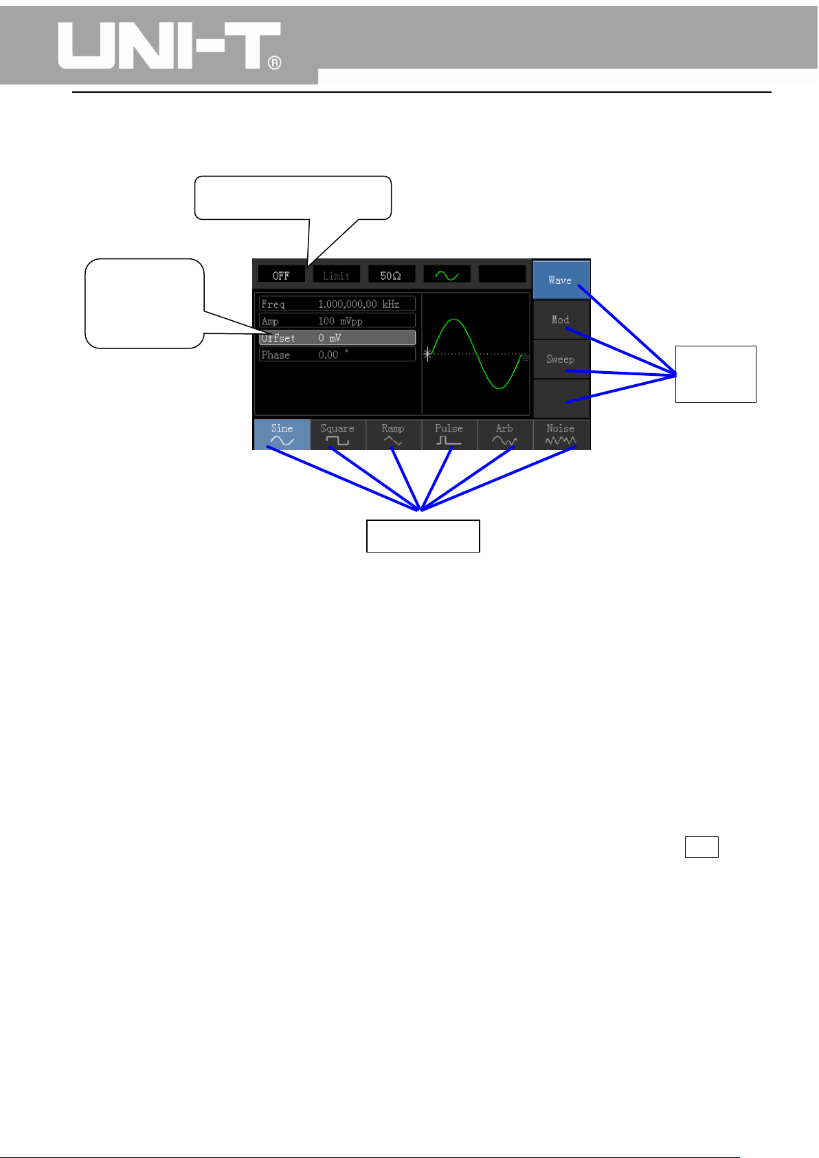
Channel Information
Softkey
Labels
Waveform
Parameter
List
Softkey
Function interface is shown in figure 2-3:
UTG1000A Series Function Generator User Manual
Figure 2-3
Detailed Description:
Channel information: 1) “ON/OFF” on the left is channel open information. 2) There is a “Limit” logo
indicates output range limit where white is valid and grey is invalid. The matched impedance of
output terminal (1Ω to 1KΩ adjustable, or high resistance, factory default is 50Ω). 3) The right side is
the current valid waveform.
Softkey labels: Softkey labels are used for identifying menu softkey functions and menu operation
softkey functions.
1) Labels on the right of screen: Highlighted display indicates that the label is selected. If not,
press corresponding softkey to select.
2) Labels at the bottom of screen: Sub label contents belongs to the next category of Type label.
Press corresponding button to select sub labels.
Waveform Parameter List: Displays parameters of current waveform in a list.
Waveform Display Area: Displays current channel’s waveform.
14
Page 16
UTG1000A Series Function Generator User Manual
Chapter 3 Quick Start
3.1 General Inspection
It is recommended to follow the steps below to check the instrument before using this device for the
first time.
3.1.1 Check for Damages Caused by Transport
If the packaging carton or the foam plastic cushions are severely damaged, please contact the UNI-T
distributor of this product immediately.
If the instrument is damaged by transport, please keep the package and contact the transport
department and the UNI-T distributor, the distributor will arrange for repairment or replacement.
3.1.2 Check Accessories
UTG1000 accessories are: Power cord, USB data cable, BNC cable (1 meter), and user CD.
If any of the accessories are missing or damaged, please contact UNI-T or local distributors of this
product.
3.1.3 Machine Inspection
If the instrument appears to be damaged, not working properly, or has failed the functionality test,
please contact UNI-T or local distributors of this product.
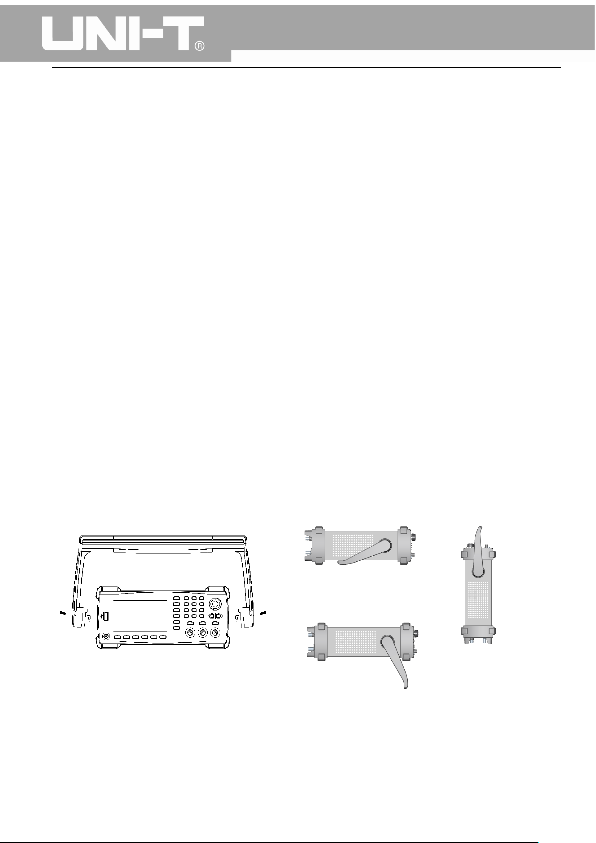
3.2 Handle Adjustment
UTG1000 series handle can be adjusted freely. If the handle position needs to be changed, please hold
the handle on both sides and pull out, then rotate the handle to the desired position, as shown in figure
3-1:
Figure 3-1
15
Page 17
UTG1000A Series Function Generator User Manual
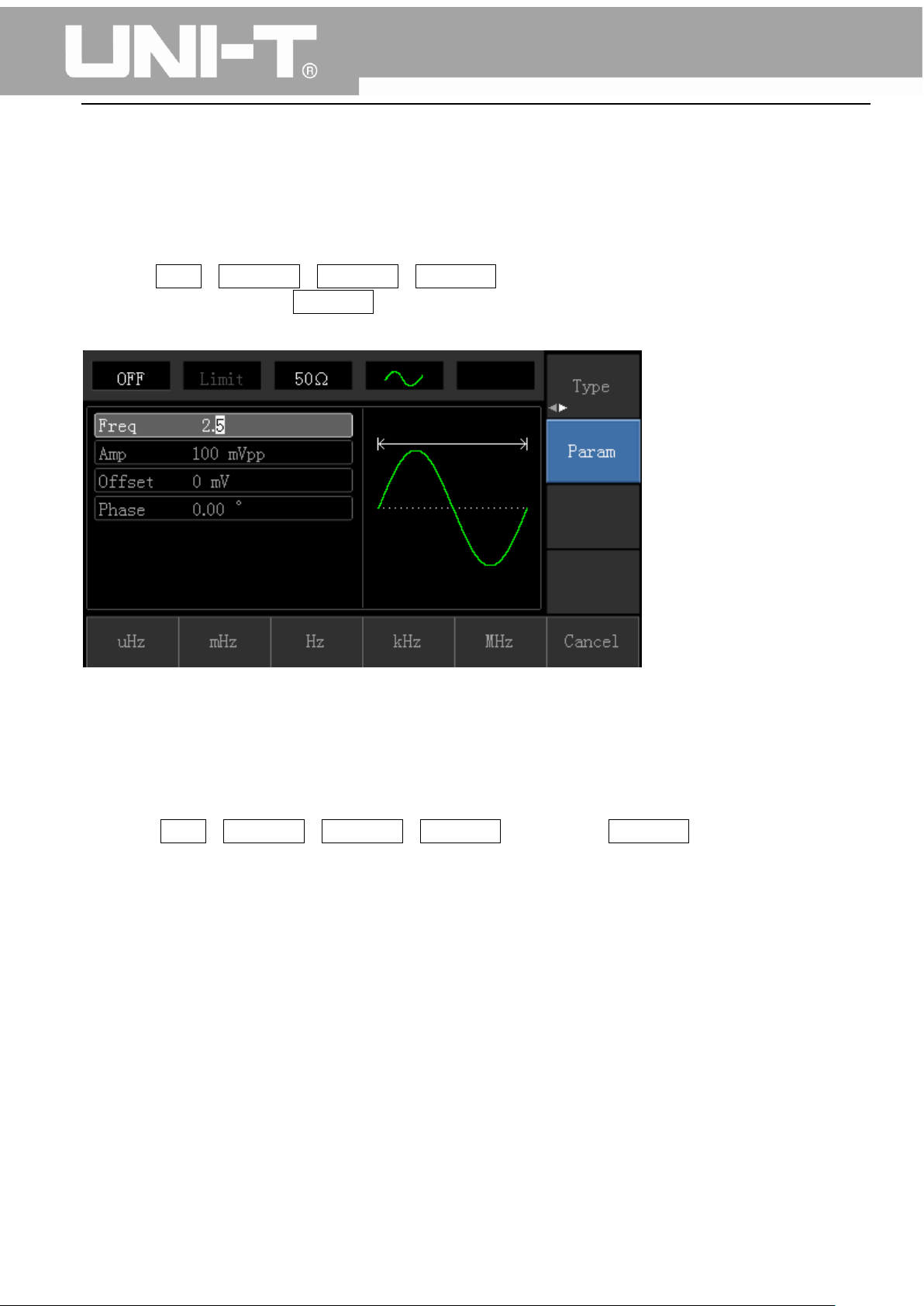
3.3 Basic Waveform Output
3.3.1 Frequency Setting
Default waveform: A sine wave of 1kHz frequency and 100mV amplitude (with 50Ω termination).
Steps for changing the frequency to 2.5MHz are shown as following:
a) Press Menu→Waveform→Parameter→Frequency in turn to frequency setting mode. Set
parameters by pressing Frequency softkey to change frequency and period.
b) Use number keyboard to input the required number of 2.5.
c) Select corresponding unit MHz.
3.3.2 Amplitude Setting
Defaultwaveform: A sine wave of 100mV peak-peak value with 50Ω termination.
Steps for changing the amplitude to 300mV are shown as following:
1. Press Menu→Waveform→Parameter→Amplitude in turn. Press Amplitude softkey again can
switch between Vpp, Vrms, and dBm.
2. Use number keys to input 300.
16
Page 18
UTG1000A Series Function Generator User Manual
3. Select required unit: Press unit softkeymVpp.
Note: This parameter can be set by multifunctional knob and direction buttons.
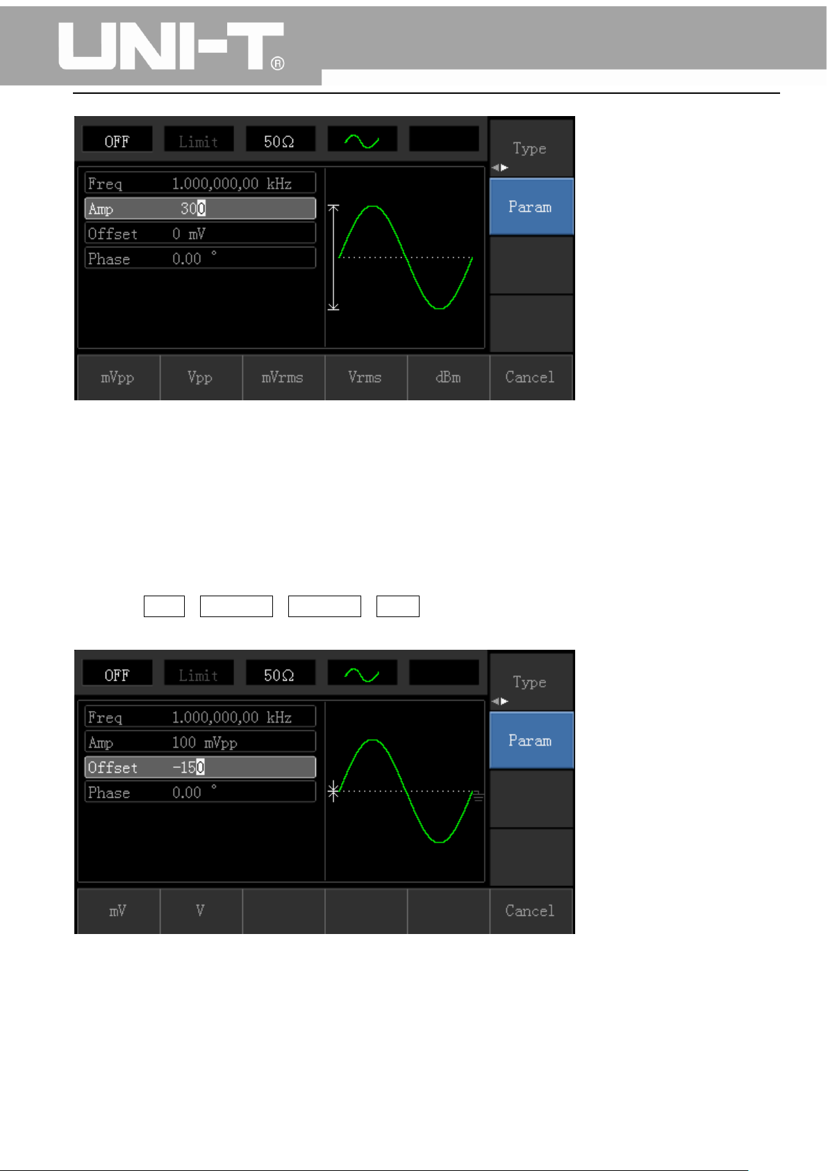
3.3.3 DC Offset Voltage Setting
The default waveform is a sine wave with 0V DC offset voltage (with 50Ω termination).Steps for
changing DC offset voltage to -150mV are shown as following:
1. Press Menu→Waveform→Parameter→Offset to enter parameter setting.
2. Use number keys to input the required number of -150.
3. Select corresponding unit mV.
Note: This parameter can be set by multifunctional knob and direction buttons.
17
Page 19
UTG1000A Series Function Generator User Manual
3.3.4 Square Wave Setting
Press Menu→Waveform→Type→Squarewave→Parameter in turn (press Type softkey to select only
when Type label is not highlighted). If parameter needs to be set, press corresponding softkey to enter
required numerical value and select the unit.
Note: This parameter can be set by multifunctional knob and direction buttons.
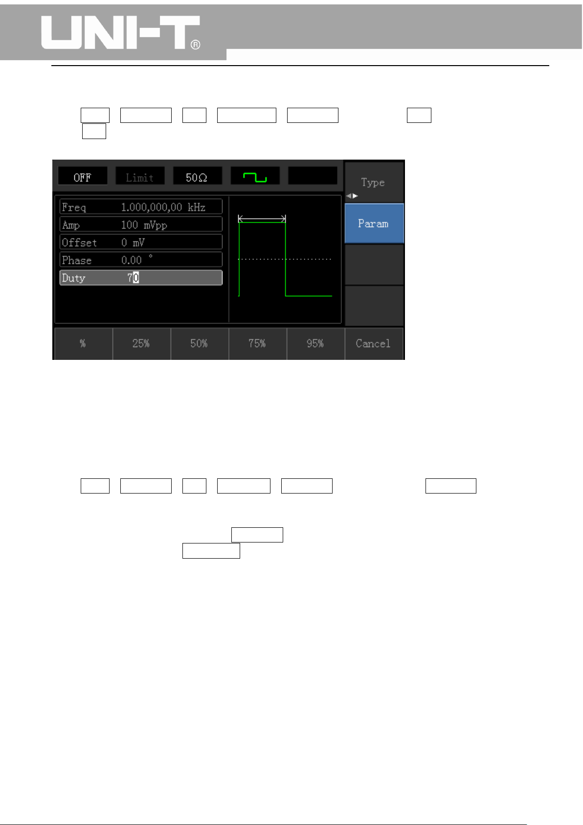
3.3.5 Pulse Wave Setting
Default duty cycle of pulse wave is 50% and rising/falling edge time is 1us. Steps for setting square
wave with 2ms period, 1.5Vpp amplitude, 0V DC offset and 25% duty cycle (limited by the minimum
pulse width specification 80ns), 200us rising time and 200us falling time are seen as following:
Press Menu→Waveform→Type→PulseWave→Parameter in turn, then press Frequency softkey to
switch to Period. Enter required number value and select the unit. When entering duty cycle value,
there is a quick label at the bottom of display, and select 25%.
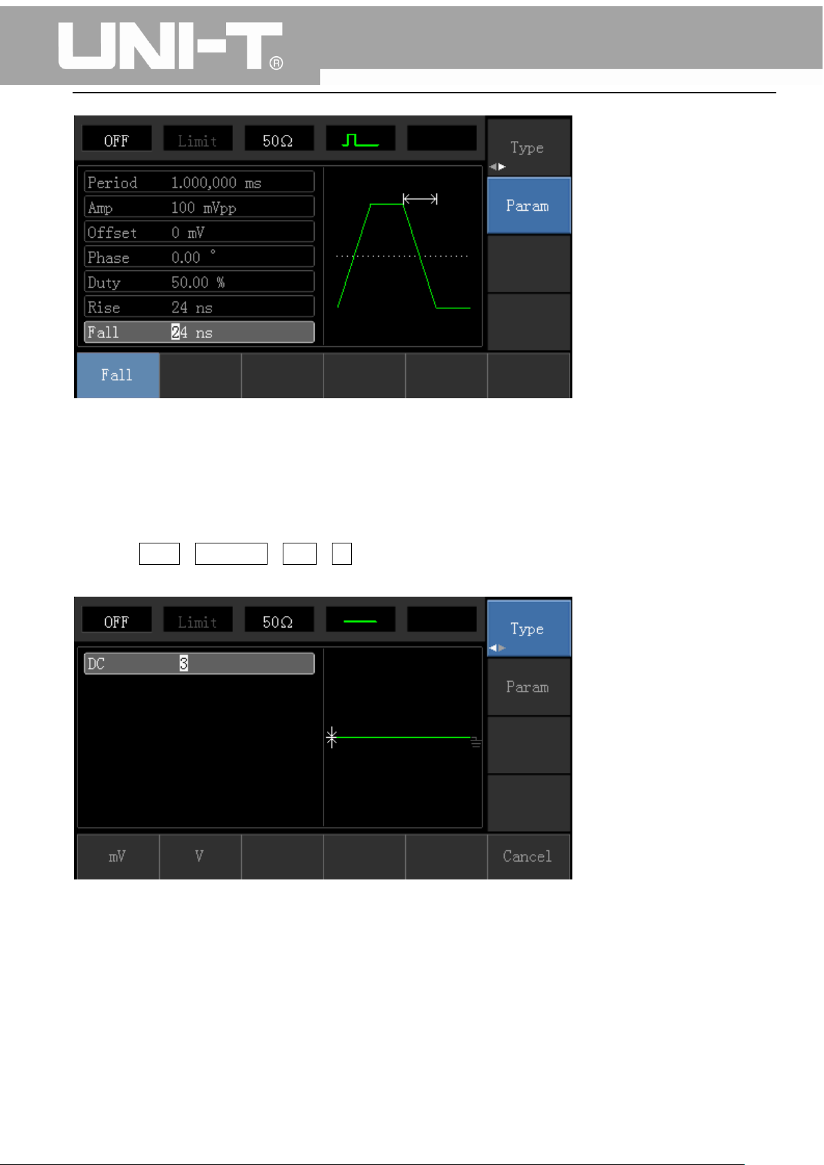
If need to set falling edge time, press Parameter softkey or rotate multifunctional knob to the right to
enter sub label, then press Falling Edge softkey to enter required number and select unit.
18
Page 20
UTG1000A Series Function Generator User Manual
Note: This parameter can be set by multifunctional knob and direction buttons.
3.3.6 DC Voltage Setting
Actually, DC voltage output is the setting of DC offset. Steps for changing DC offset voltage to 3V are
seen as following:
1. Press Menu→Waveform→Type→DC in turn to enter parameter setting mode.
2. Use number keyboard to input the required number of 3.
3. Select required unit V
Note: This parameter can be set by multifunctional knob and direction buttons.
19
Page 21
UTG1000A Series Function Generator User Manual
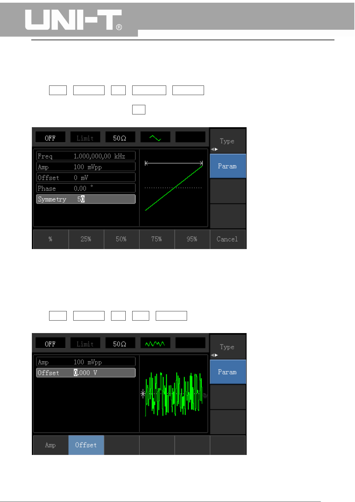
3.3.7 Ramp Wave Setting
Default symmetry degree of ramp wave is 100%. Steps for setting triangular wave with 10kHz
frequency, 2V amplitude, 0V DC offset and 50% duty cycle are seen as following:
Press Menu→Waveform→Type→RampWave→Parameter in turn to enter parameter setting mode.
Select parameter to enter edit mode, then input required numbers and select unit. Note: When enter
symmetry degree value, there is a 50% label at the bottom of display, press corresponding softkey or
use number keyboard.
Note: This parameter can be set by multifunctional knob and direction buttons.
3.3.8 Noise Wave Setting
Default Quasi Gauss noise amplitude is 100mVpp and DC offset is 0mV. Steps for setting Quasi Gauss
noise with 300mVpp amplitude and 1V DC offset are shown as following:
Press Menu→Waveform→Type→Noise→Parameter in turn to enter parameter editing mode. After
setting, enter required number and unit.
20
Page 22
UTG1000A Series Function Generator User Manual
Note: This parameter can be set by multifunctional knob and direction buttons.
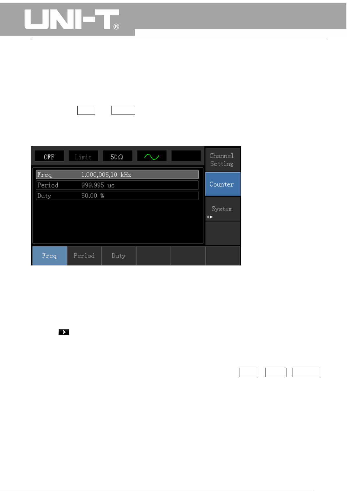
3.4 Frequency Measurement
This device is suitable for measuring frequency and duty cycle of TTL compatible signals, with frequency
range of 1Hz to 100MHz. The frequency meter takes signal through the input interface (Input/CNT
terminal). Press Utility then Counter to collect Frequency, Period, and Duty Cycle values from input
signal. Note: When there is no signal input, frequency meter parameter list always shows last
measurement value. Frequency meter will refresh only when new TTL compatible signal is present at
the Input/CNT terminal.
3.5 Build-in Help System
The build-in help system provides relevant information for any button or menu softkey. You also can
use help topic list to get help. Operations for buttons help information are shown as following:
Long press any softkey or button to display relevant information. If the content is more than 1 screen
size, use softkey or multifunctional knob to display the next screen. Press “Return” to exit.
Note!
The built-in help system provides simplified Chinese and English languages. All information, context
help and help topic are displayed in selected language. Language setting: Utility→ System→Language.
21
Page 23
UTG1000A Series Function Generator User Manual
Chapter 4 Advanced Applications 4.1 ROLL mode
4.1 Modulation Waveform Output
4.1.1 Amplitude Modulation (AM)
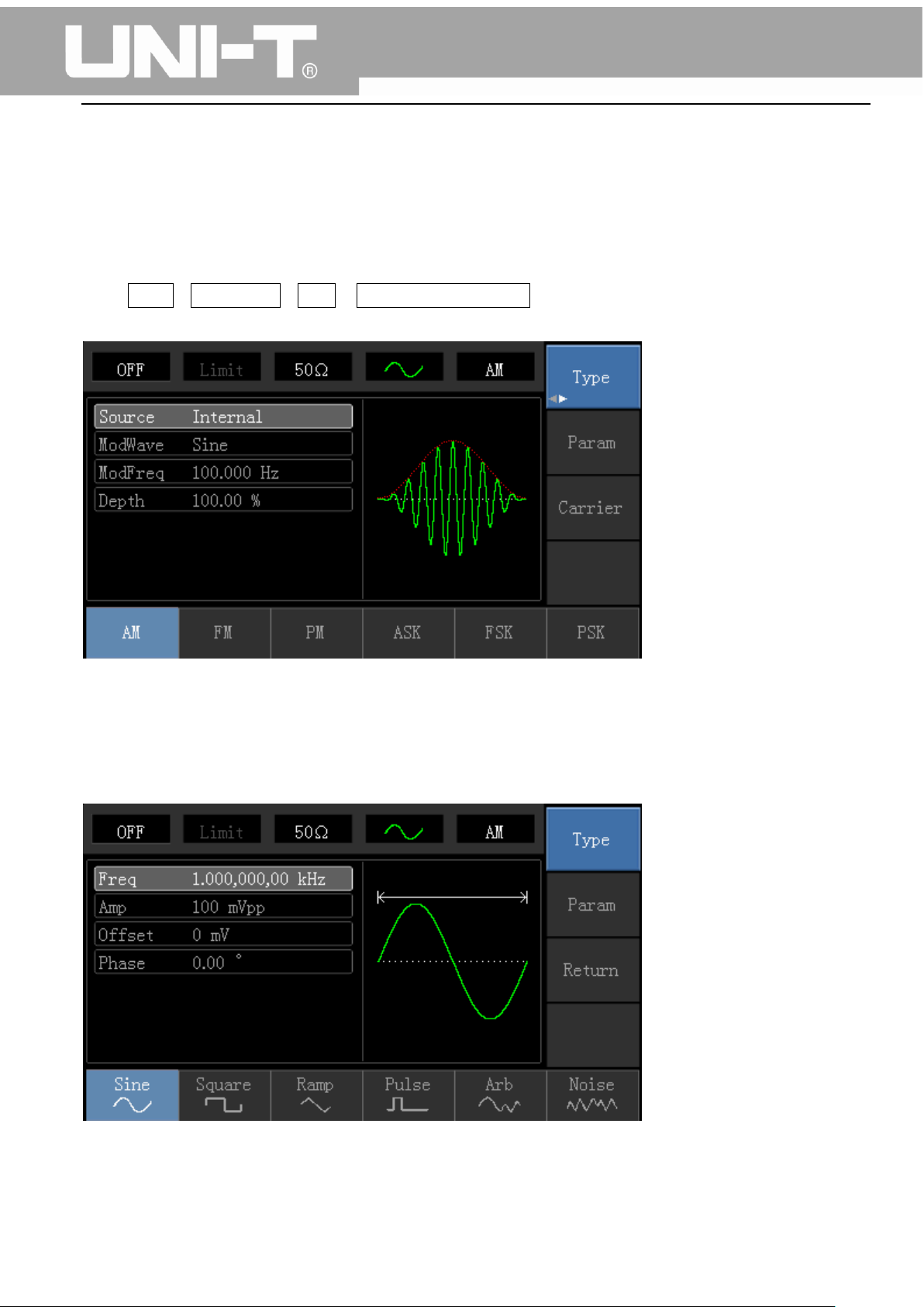
Press Menu→Modulation→Type→ Amplitude Modulation in turn to start the AM function. Then the
modulated waveform will output with modulation waveform and carrier wave set.
Carrier Waveform Selection
AM carrier waveform can be: sine wave, square wave, ramp wave or arbitrary wave (except DC), and
the default is sine wave. After selecting AM modulation, press Carrier Wave Parameter softkey to enter
carrier waveform selection interface.
22
Page 24
Carrier
Wave
Frequency
UTG1010A
UTG1005A
Minimum
Value
Maximum
Value
Minimum
Value
Maximum Value
Sine
Wave
1μHz
10MHz
1μHz
5MHz
Square
wave
1μHz
5MHz
1μHz
5MHz
Ramp
Wave
1μHz
400kHz
1μHz
400KHz
Arbitrary
Wave
1μHz
2MHz
1μHz
1MHz
UTG1000A Series Function Generator User Manual
Carrier Wave Frequency Setting
Settable carrier wave frequency range is different for different carrier waveforms. Default frequency of
all carrier wave is 1kHz. The frequency setting range of each carrier wave can be seen in the following
table:
If need to set carrier frequency, please press Parameter→ Frequency softkey, then enter required
numerical value, and select unit after selecting carrier waveform.
Modulation Source Selection
This device can select internal modulation source or external modulation source. After enabling AM
function, the default modulation source is internal. If need to change press
Parameter→ModulationSource→External in turn.
1) Internal Source
When modulation source is internal, modulation wave can be: sine wave, square wave, rising ramp
wave, falling ramp wave, arbitrary wave and noise. After enabling AM function, the default of
modulation wave is sine wave. If need to change it, press Carrier Wave →Parameter→Type in turn.
23
Page 25

UTG1000A Series Function Generator User Manual
Square wave: duty cycle is 50%
Rising Ramp Wave: symmetry degree is 100%
Falling Ramp Wave: symmetry degree is 0%
Arbitrary Wave: when arbitrary wave is modulated waveform, DDS function generator
limits arbitrary wave length as 1kpts in the way of random selection
Noise: White Gauss noise
2) External Source
When modulation source is external, parameter list will hide the modulation wave option and
modulation frequency option, and carrier waveform will be modulated by an external waveform. AM
modulation depth is controlled by ±5V signal level of external modulation input terminal. For example,
if modulation depth value is set to 100%, AM output amplitude is the maximum when external
modulation signal is +5V, AM output amplitude is the minimum when external modulation signal is -5V.
Modulation Shape Frequency Setting
When modulation source is internal, frequency of modulation shape can be modulated. After enabling
AM function, range of modulation wave frequency is 2mHz~50kHz (default is 100Hz). Press
Parameter→Modulation Frequency to change. When modulation source is external, parameter list will
hide the modulation shape option and modulation frequency option, and carrier waveform will be
modulated by an external waveform. The range of modulation signal input from external is 0Hz~ 20Hz.
Modulation Depth Setting
Modulation depth indicates the extent of amplitude variation and is expressed as percentage. Suitable
setting range of AM modulation depth is 0% to 120%, and the default is 100%. When modulation depth
is set to 0%, the constant amplitude (a half of the carrier wave amplitude that has been set) is output.
Output amplitude changes as modulation waveform changes when modulation depth is set to 100%.
The instrument output a peak-peak voltage less than ±5V (is connected with 50Ω terminal) when
modulation depth is more than 100%. If need to change, press Parameter→Modulation Depth in
amplitude function interface. When modulation source is external, output amplitude of the instrument
is controlled by ±5V signal level of external modulation input terminal (Input/CNT probe) in rear panel.
For example, if modulation depth value in parameter list has been set to 100%, AM output amplitude is
the maximum when external modulation signal is +5V, AM output amplitude is the minimum when
external modulation signal is -5V.
Comprehensive Example
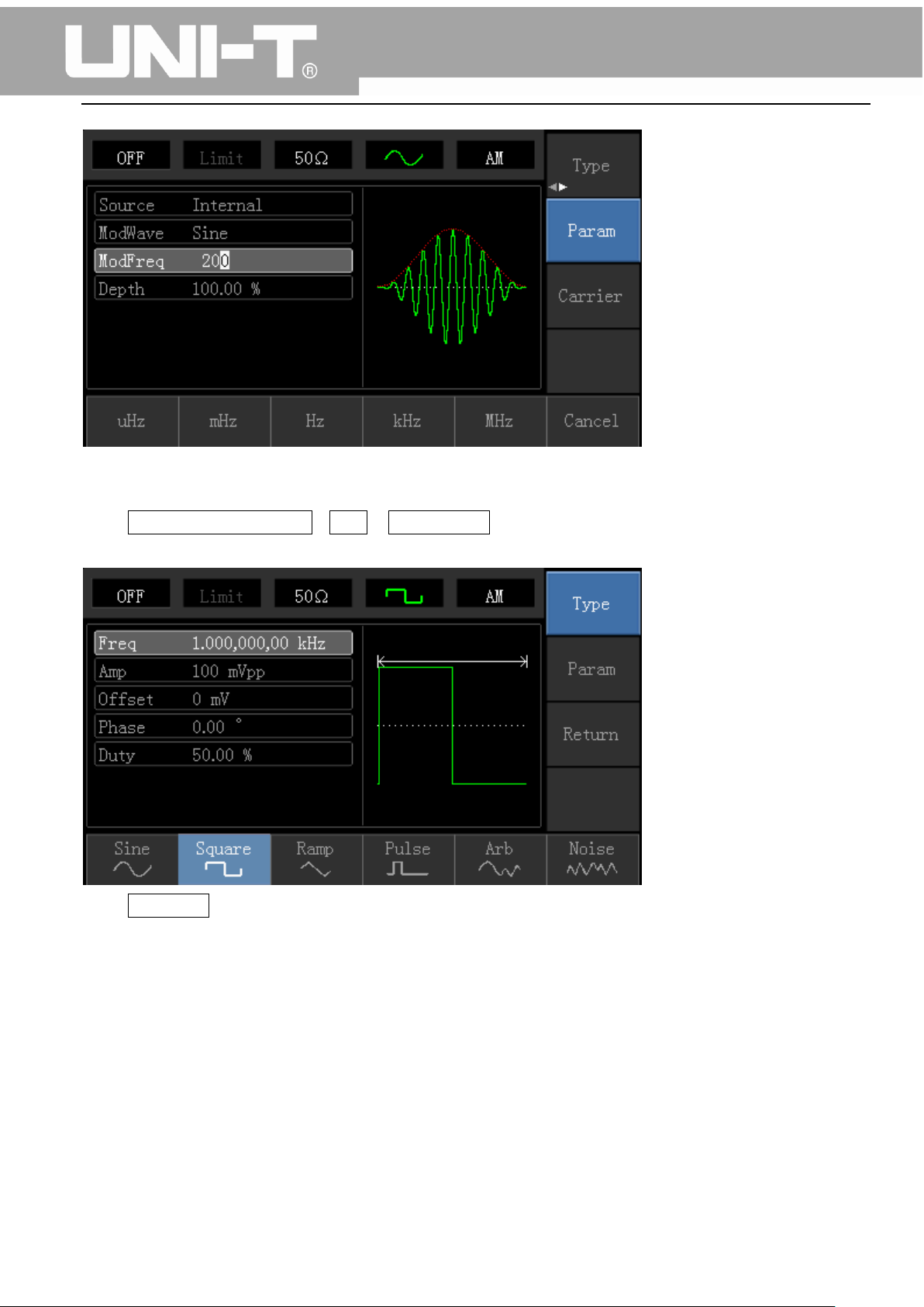
Firstly, make the instrument work in amplitude modulation (AM) mode, then set a sine wave with
200Hz from the internal of the instrument as a modulation signal and a square wave with frequency of
10kHz, amplitude of 200mVpp and duty cycle of 45% as a carrier wave signal. Finally, set modulation
depth to 80%. Specific steps are seen as following:
1) Enable Amplitude Modulation (AM) Function
24
Page 26
UTG1000A Series Function Generator User Manual
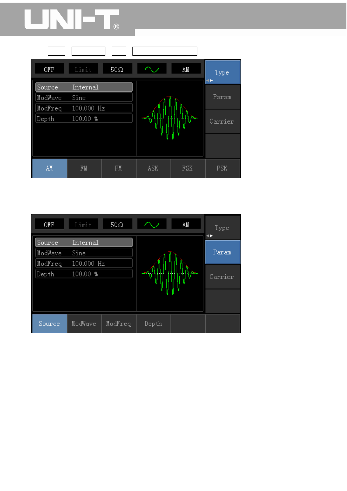
Press Menu→Modulation→Type→Amplitude Modulation in turn.
2) Set Modulation Signal Parameter
After enabling the AM function, press Parameter softkey and the interface will appear as following:
Press corresponding softkey, then enter required numerical value, and select the unit.
25
Page 27
UTG1000A Series Function Generator User Manual
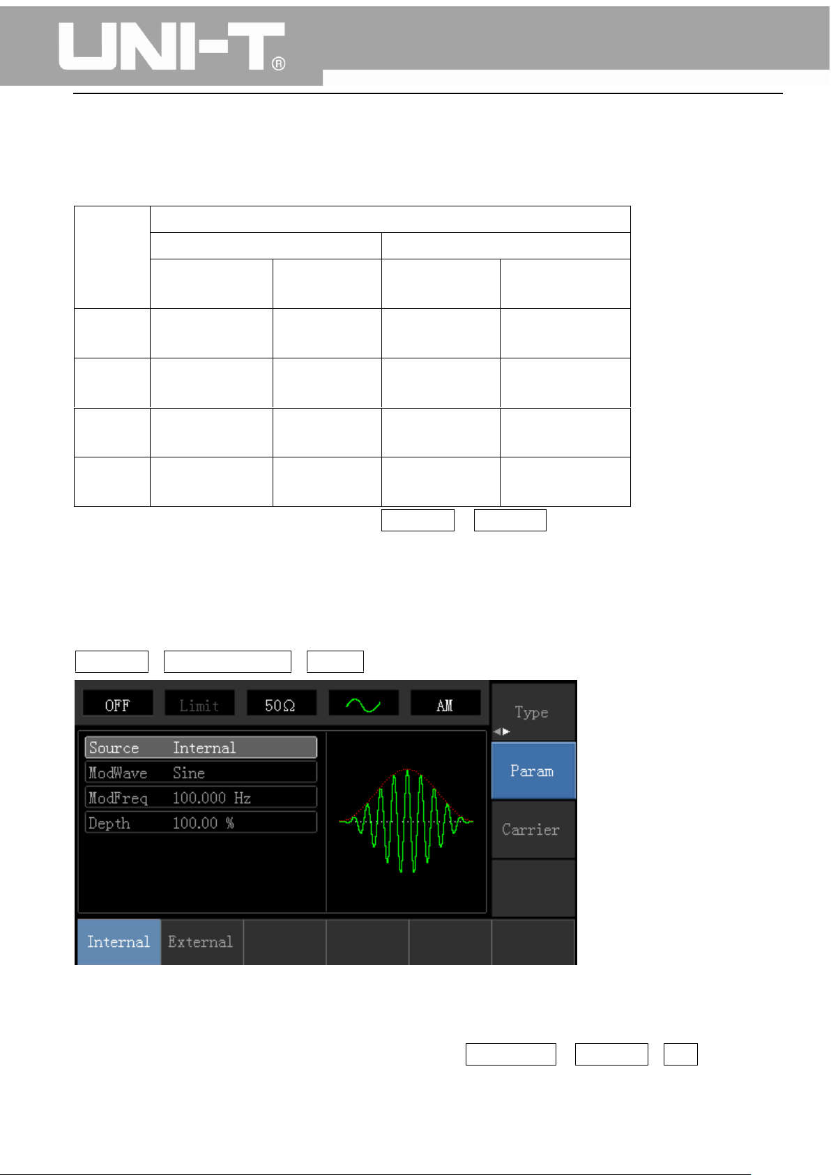
3) Set Carrier Wave Signal Parameter
Press Carrier Wave Parameter→Type→ Square Wave in turn to select square wave as carrier wave
signal.
Press Parameter softkey again, and the interface will pop up as following:
26
Page 28
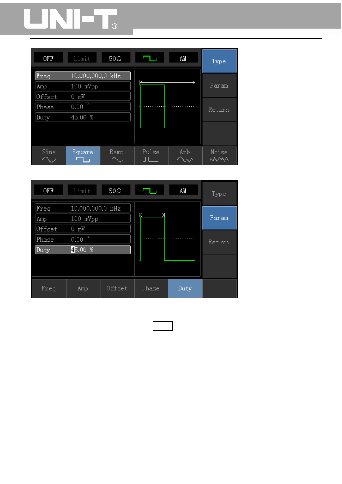
UTG1000A Series Function Generator User Manual
Press corresponding softkey, then enter required numerical value, and select the unit.
4) Set Modulation Depth
After setting carrier wave parameter, press Return softkey to back to the following interface for setting
modulation depth.
27
Page 29
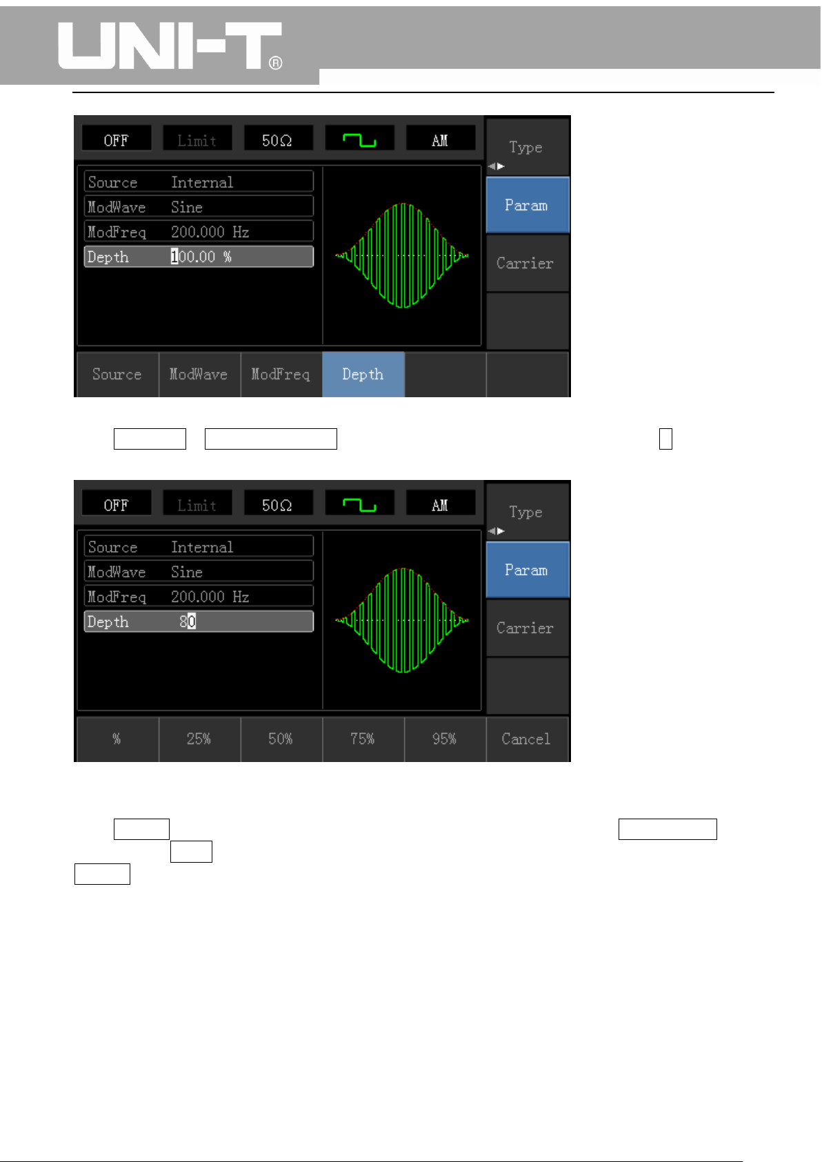
UTG1000A Series Function Generator User Manual
Press Parameter →Modulation Degree softkey again, then enter number 80 and press % softkey with
number keyboard for setting modulation depth.
5) Enable Channel Output
Press Channel button start channel output quickly. Or enable output by pressing Channel Setup softkey
after pressing Utility button and popping up labels. After channel output is opened, backlight of
Channel button is on, and on the right side of channel information label, the font “OFF” changes to
“ON”, meaning open channel output.
28
Page 30

UTG1000A Series Function Generator User Manual
The shape of AM modulation waveform checked through oscilloscope is shown as following:
4.1.2 Frequency Modulation (FM)
In frequency modulation, modulated waveform is usually composed of carrier wave and modulation
shape. Carrier wave frequency will change as the amplitude of modulation shape changes.
Press Menu→Modulation→Type→ Frequency Modulation in turn to start the FM function. The device
will output modulated waveform with modulation waveform and carrier wave set currently.
29
Page 31

Carrier
Wave
Waveform
Frequency
UTG1010A
UTG1005A
Minimum
Maximum
Minimum
Maximum
UTG1000A Series Function Generator User Manual
Carrier Wave Waveform Selection
FM carrier waveform can be: Sine wave, square wave, ramp wave, pulse wave, arbitrary wave (except
DC) and noise (the default is sine wave). After selecting FM modulation, press Carrier Wave Parameter
softkey to enter carrier waveform selection interface.
Carrier Wave Frequency Setting
Settable carrier wave frequency range is different of different carrier waveform. Default frequency of
all carrier wave is 1kHz. The frequency setting range of each carrier wave can be seen in the following
table:
30
Page 32

Sine Wave
1μHz
10MHz
1μHz
5MHz
Square
wave
1μHz
5MHz
1μHz
5MHz
Ramp
Wave
1μHz
400kHz
1μHz
400KHz
Arbitrary
Wave
1μHz
2MHz
1μHz
1MHz
UTG1000A Series Function Generator User Manual
Press Parameter→Frequency softkey in turn to set carrier wave frequency, then enter required
numerical value, and select unit.
Modulation Source Selection
This device can select internal modulation source or external modulation source. After enabling FM
function, the default of modulation source is internal. If need to change, press
1) Internal Source
When modulation source is internal, modulation wave can be: sine wave, square wave, rising ramp
wave, falling ramp wave, arbitrary wave and noise. After enabling FM function, the default of
modulation wave is sine wave. If need to change, press Carrier Wave →Parameter→Type in turn.
Square wave: duty cycle is 50%
Lead Ramp Wave: symmetry degree is 100%
Tail Ramp Wave: symmetry degree is 0%
Arbitrary Wave: Arbitrary wave length limit is 1kpts
Noise: White Gauss noise
2) External Source
When modulation source is external, carrier waveform will be modulated by an external waveform. FM
frequency deviation is controlled by ±5V signal level of external modulation input terminal on front
31
Page 33

UTG1000A Series Function Generator User Manual
panel. In positive signal level, FM output frequency is more than carrier wave frequency, while in
negative signal level, FM output frequency is less than carrier wave frequency. Low external signal level
has small deviation. For example, if the frequency offset is set to 1kHz and the external modulation
signal is +5V, FM output frequency will be the current carrier frequency plus 1kHz. When the external
modulation signal is -5V, FM output frequency will be the current carrier frequency minus 1kHz.
Modulation Shape Frequency Setting
When modulation source is internal, frequency of modulation shape can be modulated. After enabling
FM function, the default of modulation shape frequency is 100Hz. If need to change, press Carrier
Wave Parameter→ Modulation Frequency in turn, and the modulation frequency range is 2mHz to
50kHz. When modulation source is external, parameter list will hide the modulation shape option and
modulation frequency option, and carrier waveform will be modulated by an external waveform. The
range of modulation signal input from external is 0Hz to 20Hz.
Frequency Deviation Setting
Frequency deviation represents the difference between frequency of the FM modulated waveform and
the carrier frequency. Settable range of FM frequency deviation is from 1μHz to the maximum of
current carrier wave frequency, and the default value is 1kHz. If need to change, press
Parameter→Frequency Deviation in turn.
Frequency deviation is less than carrier wave frequency. If frequency deviation value is set higher
than carrier wave frequency, the device will automatically set the offset value to the carrier
frequency’s maximum allowable frequency.
Sum of frequency deviation and carrier wave frequency is less than the allowed maximal frequency
of current carrier wave. If the frequency deviation value is set to an invalid value, the device will
automatically set the offset value to the carrier frequency’s maximum allowable frequency.
Comprehensive Example:
Make the instrument work in frequency modulation (FM) mode, then set a sine wave with 2kHz from
the internal of the instrument as a modulation signal and a square wave with frequency of 10kHz and
amplitude of 100mVpp as a carrier wave signal. Finally, set frequency deviation to 5kHz. Specific steps
are seen as following:
1) Enable Frequency Modulation (FM) Function
Press Menu→Modulation→Type→Frequency Modulation in turn to start the FM function.
32
Page 34

UTG1000A Series Function Generator User Manual
2) Set Modulation Signal Parameter
Press Parameter softkey. Then the interface will show as following:
Press corresponding softkey, then enter required numerical value, and select the unit.
33
Page 35

UTG1000A Series Function Generator User Manual
3) Set Carrier Wave Signal Parameter
Press Carrier Wave Parameter→Type→Sine Wave in turn to select sine wave as carrier wave signal.
Press Parameter softkey, and the interface will pop up as following:
34
Page 36

UTG1000A Series Function Generator User Manual
Press corresponding softkey first, then enter required numerical value, and select the unit.
4) Set Frequency Deviation
After setting carrier wave parameter, press Return softkey to back to the following interface for setting
frequency deviation.
35
Page 37

UTG1000A Series Function Generator User Manual
Press Parameter →Frequency Deviation softkey, then enter number 5 and press kHz softkey with
number keyboard for setting frequency deviation.
5) Enable Channel Output
36
Page 38

UTG1000A Series Function Generator User Manual
Press Channel button to open channel output.
The shape of FM modulation waveform checked through oscilloscope is shown as following:
4.1.3 Phase Modulation (PM)
In phase modulation, modulated waveform is usually composed of carrier wave and modulation wave.
The phase of carrier wave will change as the amplitude of modulation shape changes.
Press Menu→Modulation→Type→ Phase Modulation in turn to start the PM function. The device will
output modulated waveform with modulation waveform and carrier wave set currently.
37
Page 39

Carrier
Wave
Wavefrom
Frequency
UTG1010A
UTG1005A
Minimum
Value
Maximum
Value
Minimum Value
Maximum
Value
UTG1000A Series Function Generator User Manual
Carrier Wave Waveform Selection
PM carrier waveform can be: Sine wave, square wave, ramp wave or arbitrary wave (except DC), and
the default is sine wave. Press Carrier Wave Parameter softkey to select carrier waveform.
Carrier Wave Frequency Setting
Settable carrier wave frequency range is different of different carrier waveform. Default frequency of
all carrier wave is 1kHz. The frequency setting range of each carrier wave can be seen in the following
table:
38
Page 40

Sine Wave
1μHz
10MHz
1μHz
5MHz
Square
wave
1μHz
5MHz
1μHz
5MHz
Ramp
Wave
1μHz
400kHz
1μHz
400KHz
Arbitrary
Wave
1μHz
2MHz
1μHz
1MHz
UTG1000A Series Function Generator User Manual
Press Parameter→ Frequency softkey to enter carrier wave frequency setting, then enter required
numerical value, and select unit.
Modulation Source Selection
This device can select internal modulation source or external modulation source. After enabling PM
function, the default of modulation source is internal. If need to change, press
Parameter→ModulationSource→External in turn.
1) Internal Source
When modulation source is internal, modulation shape can be: sine wave, square wave, rising ramp
wave, falling ramp wave, arbitrary wave and noise. After enabling PM function, the default of
modulation wave is sine wave. If need to change, press Carrier Wave Parameter→Type in turn.
2) External Source
When modulation source is external, carrier waveform will be modulated by an external waveform. PM
phase deviation is controlled by ±5V signal level of external modulation input terminal on front panel.
For example, if phase deviation value in parameter list has been set to 180º, +5V of external
modulation signal is equivalent to 180º phase shift.
Modulation Shape Frequency Setting
39
Page 41

UTG1000A Series Function Generator User Manual
When modulation source is internal, frequency of modulation shape can be modulated. After enabling
PM function, the default of modulation shape frequency is 100Hz. If need to change, press Carrier
Wave Parameter→Modulation Frequency in turn, and the modulation frequency range is 2mHz to
50kHz. When modulation source is external, carrier waveform will be modulated by an external
waveform. The range of modulation signal input from external is 0Hz to 20Hz.
Phase Deviation Setting
Phase deviation indicates the change between the phases of PM modulated waveform and the phase
of carrier wave phase. Settable range of PM phase deviation is from 0º to 360º, and the default value is
50º. If need to change, press Parameter→Phase Deviation in turn.
Comprehensive Example
Firstly, make the instrument work in phase modulation (PM) mode, then set a sine wave with 200Hz
from the internal of the instrument as a modulation signal and a square with frequency of 900Hz and
amplitude of 100mVpp as a carrier wave signal. Finally, set the phase deviation to 200º. Specific steps
are seen as following:
1) Enable Phase Modulation (PM) Function
Press Menu→Modulation→Type→Phase Modulation in turn to start the PM function.
2) Set Modulation Signal Parameter
Press Parameter softkey and the interface will show as following:
40
Page 42

UTG1000A Series Function Generator User Manual
Press corresponding softkey first, then enter required numerical value, and select the unit.
3) Set Carrier Wave Signal Parameter
Press Carrier Wave Parameter→Type→Sine Wave in turn to select sine wave as carrier wave signal.
41
Page 43

UTG1000A Series Function Generator User Manual
Press Parameter softkey, and the interface will pop up as following:
Press corresponding softkey, then enter required numerical value, and select the unit.
42
Page 44

UTG1000A Series Function Generator User Manual
4) Set Phase Deviation
Press Return softkey to back to the following interface for setting phase modulation.
Press Parameter →Phase Deviation softkey, then enter number 200 and press º softkey with number
keyboard for setting phase deviation.
5) Enable Channel Output
Press Channel button to open channel output quickly.
43
Page 45

UTG1000A Series Function Generator User Manual
The shape of PM modulation waveform checked through oscilloscope is shown as following:
4.1.4 Amplitude Shift Keying (ASK)
ASK represents digital signal “0” and “1” by changing amplitude of carrier wave signal. Carrier wave
signal with different amplitude will be output on the basis of different logic of modulation signal.
ASK Modulation Selection
Press Menu→Modulation→Type→Amplitude Shift Keying in turn to start the ASK function, the device
will output modulated waveform with ASK rate and carrier wave set currently.
44
Page 46

Carrier
Wave
Waveform
Frequency
UTG1010A
UTG1005A
Minimum
Value
Maximum
Value
Minimum
Value
Maximum
Value
UTG1000A Series Function Generator User Manual
Carrier Wave Waveform Selection
ASK carrier waveform can be: Sine wave, square, ramp wave or arbitrary wave (except DC), and the
default is sine wave. Press Carrier Wave Parameter softkey to enter carrier waveform selection
interface.
Carrier Wave Frequency Setting
Settable carrier wave frequency range is different of different carrier waveform. Default frequency of
all carrier wave is 1kHz. The frequency setting range of each carrier wave can be seen in the following
table:
45
Page 47

Sine Wave
1μHz
10MHz
1μHz
5MHz
Square
Wave
1μHz
5MHz
1μHz
5MHz
Ramp
Wave
1μHz
400kHz
1μHz
400KHz
Arbitrary
Wave
1μHz
2MHz
1μHz
1MHz
UTG1000A Series Function Generator User Manual
Press Parameter→Frequency softkey, then enter required number value, and select unit.
Modulation Source Selection
The device can select internal modulation source or external modulation source. After enabling ASK
function, the default of modulation source is internal. If need to change, press
Parameter→ModulationSource→External in turn.
1) Internal Source
When modulation source is internal, internal modulation wave is a square wave of 50% duty cycle (not
adjustable). The ASK rate can be set to customize modulated waveform amplitude hopping frequency.
2) External Source
When modulation source is external, carrier waveform will be modulated by an external waveform. ASK
output amplitude is determined by the logic level of modulation interface on front panel. For example,
output the carrier wave amplitude of current setting when external input logic is low, and output
carrier wave amplitude less than the amplitude of current setting when external input logic is high.
ASK Rate Setting
46
Page 48

UTG1000A Series Function Generator User Manual
When modulation source is internal, frequency of ASK amplitude jump can be modulated. After
enabling ASK function, ASK rate can be set and the settable range is 2mHz to 100kHz, the default rate is
1kHz. If need to change, press Carrier Wave Parameter→Rate in turn.
Comprehensive Example
Make the instrument work in amplitude shift keying (ASK) mode, then set a logic signal with 300Hz
from the internal of the instrument as a modulation signal and a sine wave with frequency of 15kHz
and amplitude of 2Vpp as a carrier wave signal. Specific steps are seen as following:
1) Enable Amplitude Shift Keying (ASK) Function
Press Menu→Modulation→Type→Amplitude Shift Keying in turn to start the ASK function.
2) Set Carrier Wave Signal Parameter
Press Carrier Wave Parameter→Type→Sine Wave in turn
Press Parameter softkey, and the interface will pop up as following:
47
Page 49

UTG1000A Series Function Generator User Manual
Press corresponding softkey, then enter required numerical value, and select the unit.
3) Set ASK Rate
After setting carrier wave parameter, press Return softkey to go back to the following interface for
setting phase modulation.
48
Page 50

UTG1000A Series Function Generator User Manual
Press Parameter →Rate softkey again, then enter number 300 and press Hz softkey with number
keyboard for setting ASK rate.
4) Enable Channel Output
Press Channel button to open channel output quickly.
49
Page 51

UTG1000A Series Function Generator User Manual
The shape of ASK modulation waveform checked through oscilloscope is shown as following:
4.1.5 Frequency Shift Keying (FSK)
In frequency shift keying, rate of carrier wave frequency and hopping frequency can be changed.
FSK Modulation Selection
Press Menu→Modulation→Type→Frequency Shift Keying in turn to start the FSK function. The device
will output modulated waveform with current setting.
50
Page 52

Carrier
Wave
Waveform
Frequency
UTG1010A
UTG1005A
Minimum
Value
Maximum
Value
Minimum
Value
Maximum
Value
Sine Wave
1μHz
10MHz
1μHz
5MHz
UTG1000A Series Function Generator User Manual
Carrier Wave Waveform Selection
Press Carrier Wave Parameter softkey to enter carrier waveform selection interface. FSK carrier
waveform can be: sine wave, square wave, ramp wave or arbitrary wave (except DC), and the default is
sine wave.
Carrier Wave Frequency Setting
Settable carrier wave frequency range is different of different carrier waveform. Default frequency of
all carrier wave is 1kHz. The frequency setting range of each carrier wave can be seen in the following
table:
51
Page 53

Square
Wave
1μHz
5MHz
1μHz
5MHz
Ramp
Wave
1μHz
400kHz
1μHz
400KHz
Arbitrary
Wave
1μHz
2MHz
1μHz
1MHz
UTG1000A Series Function Generator User Manual
Press Parameter→Frequency softkey, then enter required numerical value, and select unit.
Modulation Source Selection
The device can select internal modulation source or external modulation source. After enabling FSK
function, the default of modulation source is internal. If need to change, press
Parameter→ModulationSource→External in turn.
1) Internal Source
When modulation source is internal, internal modulation wave is a square of 50% duty cycle (not
adjustable). The FSK rate can be set to customize the moving frequency between carrier wave
frequency and hop frequency.
2) External Source
When modulation source is external, carrier waveform will be modulated by an external waveform. FSK
output frequency is determined by the logic level of modulation interface on front panel. For example,
output the carrier wave frequency when external output logic is low, and output hop frequency when
external input logic is high.
Hop Frequency Setting
52
Page 54

Carrier
Wave
Waveform
Frequency
UTG1010A
UTG1005A
Minimum
Value
Maximum
Value
Minimum
Value
Maximum
Value
Sine Wave
1μHz
10MHz
1μHz
5MHz
Square
Wave
1μHz
5MHz
1μHz
5MHz
Ramp
Wave
1μHz
400kHz
1μHz
400KHz
Arbitrary
Wave
1μHz
2MHz
1μHz
1MHz
UTG1000A Series Function Generator User Manual
After enabling FSK function, the default of hop frequency is 2MHz. If need to change, press
Parameter→Hop Frequency in turn. Settable range of hop frequency is determined by carrier wave
waveform. See the following table for setting range of each carrier wave frequency:
FSK Rate Setting
When modulation source is internal, the moving frequency between carrier wave frequency and hop
frequency can be set. After enabling FSK function, FSK rate can be set and the settable range is 2mHz to
100kHz, the default rate is 1kHz. If need to change, press Carrier Wave Parameter→Rate in turn.
Comprehensive Example
Firstly, make the instrument work in frequency shift keying (FSK) mode, then set a sine wave with 2kHz
and 1Vpp from the internal of the instrument as a carrier wave signal, and set hop frequency to 800 Hz,
finally, make carrier wave frequency and hop frequency move between each other with 200Hz
frequency. Specific steps are seen as following:
1) Enable Frequency Shift Keying (FSK) Function
Press Menu→Modulation→Type→Frequency Shift Keying in turn to start the FSK function.
53
Page 55

UTG1000A Series Function Generator User Manual
2) Set Carrier Wave Signal Parameter
Press Carrier Wave Parameter→Type→Sine Wave in turn to select sine wave as carrier wave.
Press Parameter softkey again, and the interface will pop up as following:
Press corresponding softkey first, then enter required numerical value, and select the unit.
54
Page 56

3) Set Hop Frequency and FSK Rate
Press Return softkey to go back to the following interface.
UTG1000A Series Function Generator User Manual
Press Parameter softkey again, and the interface will pop up as following:
55
Page 57

UTG1000A Series Function Generator User Manual
Press corresponding softkey first, then enter required numerical value, and select the unit.
4) Enable Channel Output
Press Channel button on front panel to open channel output.
56
Page 58

UTG1000A Series Function Generator User Manual
The shape of FSK modulation waveform checked through oscilloscope is shown as following:
4.1.6 Phase Shift Keying (PSK)
In phase shift keying, DDS function generator can be configured to move between two preset phase
(carrier wave phase and modulation phase). Output carrier wave signal phase or hop signal phase on
the basis of the logic of modulation signal.
PSK Modulation Selection
Press Menu→Modulation→Type→ Phase Shift Keying in turn to start the PSK function. The device will
output modulated waveform with carrier wave phase (the default is 0º and is not adjustable) of current
setting and modulation phase.
57
Page 59

Carrier
Wave
Waveform
Frequency
UTG1010A
UTG1005A
Minimum
Value
Maximum
Value
Minimum
Value
Maximum
Value
Sine Wave
1μHz
10MHz
1μHz
5MHz
UTG1000A Series Function Generator User Manual
Carrier Wave Waveform Selection
PSK carrier waveform can be: Sine wave, square, ramp wave or arbitrary wave (except DC), and the
default is sine wave. Press Carrier Wave Parameter softkey to enter carrier waveform selection
interface.
Carrier Wave Frequency Setting
Settable carrier wave frequency range is different of different carrier waveform. Default frequency of
all carrier wave is 1kHz. The frequency setting range of each carrier wave can be seen in the following
table:
58
Page 60

Square
Wave
1μHz
5MHz
1μHz
5MHz
Ramp
Wave
1μHz
400kHz
1μHz
400KHz
Arbitrary
Wave
1μHz
2MHz
1μHz
1MHz
UTG1000A Series Function Generator User Manual
Press Parameter→Frequency softkey, then enter required numerical value, and select unit.
Modulation Source Selection
UTG1000A function/arbitrary waveform generator can select internal modulation source or external
modulation source. After enabling PSK function, the default of modulation source is internal. If need to
change, press Parameter→Modulation→Source→External in turn.
1) Internal Source
When modulation source is internal, internal modulation wave is a square wave of 50% duty cycle (not
adjustable). The PSK rate can be set to customize the moving frequency between carrier wave phase
and modulation phase.
2) External Source
When modulation source is external, carrier waveform will be modulated by an external waveform.
Carrier wave phase will be output when external input logic is low, and modulation phase will be
output when external input logic is high.
PSK Rate Setting
When modulation source is internal, the moving frequency between carrier wave phase and
modulation phase can be set. After enabling PSK function, PSK rate can be set and the settable range is
59
Page 61

UTG1000A Series Function Generator User Manual
2mHz to 100kHz, the default rate is 100Hz. If need to change, press Carrier Wave Parameter→Rate in
turn.
Modulation Phase Setting
Modulation phase indicates the change between the phases of PSK modulated waveform and the
phase of carrier wave phase. Settable range of PSK phase is from 0º to 360º, and the default value is 0º.
If need to change, press Parameter→Phase in turn.
Comprehensive Example
Make the instrument work in phase shift keying (PSK) mode, then set a sine wave with 2kHz and 2Vpp
from the internal of the instrument as a carrier wave signal, finally, make carrier wave phase and
modulation phase move between each other with 1kHz frequency. Specific steps are seen as following:
1) Enable Phase Shift Keying (PSK) Function
Press Menu→Modulation→Type→Phase Shift Keying in turn to start the PSK function.
2) Set Carrier Wave Signal Parameter
Press Carrier Wave Parameter→Type→Sine Wave in turn to select sine wave as carrier wave signal.
60
Page 62

UTG1000A Series Function Generator User Manual
Press Parameter softkey, and the interface will pop up as following:
Press corresponding softkey, then enter required numerical value, and select the unit.
61
Page 63

UTG1000A Series Function Generator User Manual
3) Set PSK Rate and Modulation Phase
Press Return softkey to go back to the following interface:
Press Parameter softkey, and the interface will pop up as following:
Press corresponding softkey, then enter required numerical value, and select the unit.
62
Page 64

4) Enable Channel Output
Press Channel button to open channel output quickly.
UTG1000A Series Function Generator User Manual
The shape of PSK modulation waveform checked through oscilloscope is shown as following:
63
Page 65

4.1.7 Pulse Width Modulation (PWM)
UTG1000A Series Function Generator User Manual
In pulse width modulation, modulated waveform is usually composed of carrier wave and modulation
shape, and the pulse width of carrier wave will change as modulation shape amplitude changes.
PWM Modulation Selection
Press Menu→Modulation→Type→Pulse Width Modulation in turn to start the PWMK function. The
device will output modulated waveform with modulation waveform and carrier wave of current setting.
Carrier Wave Waveform
PWM carrier wave waveform can only be pulse wave. After PWM modulation, press carrier parameter
softkey to enter carrier wave waveform selection interface, then it can be seen that Pulse Wave label is
selected automatically.
64
Page 66

UTG1000A Series Function Generator User Manual
Carrier Wave Frequency Setting
Settable range of pulse wave frequency is from 500uH to 25MHz, and the default frequency is 1kHz.
Press Parameter→ Frequency softkey to change frequency, then enter required numerical value, and
select unit.
Carrier Wave Duty Cycle Setting
Settable range of pulse wave duty cycle is 0.01%~99.99%, and the default duty cycle is 50%. Press
Parameter→ Frequency softkey to change, then enter required numerical value, and select unit.
Modulation Source Selection
The device can select internal modulation source or external modulation source. If need to change,
press Parameter→ModulationSource→External in turn.
1) Internal Source
65
Page 67

UTG1000A Series Function Generator User Manual
When modulation source is internal, modulation wave can be: sine wave, square wave, rising ramp
wave, falling ramp wave, arbitrary wave and noise, and the default wave is sine wave. If need to change,
press Carrier Wave ParameterModulation Waveform in turn.
Square wave: duty cycle 50%
Lead Ramp Wave: symmetry degree is 100%
Tail Ramp Wave: symmetry degree is 0%
Arbitrary Wave: Arbitrary wave length limit is 1kpts
Noise: White Gauss noise
2) External Source
When modulation source is external, carrier wave waveform will be modulated by an external
waveform.
Modulation Shape Frequency Setting
When modulation source is internal, frequency of modulation wave can be modulated (range is
2mHz~20kHz). After enabling PWM function, the default of modulation wave frequency is 1kHz. If need
to change, press Carrier Wave Parameter→Modulation Frequency in turn. When modulation source is
external, carrier wave waveform (pulse wave) will be modulated by an external waveform. The range of
modulation signal input from external is 0Hz to 20kHz.
Duty Cycle Deviation Setting
The duty cycle deviation represents the difference between the duty cycle of the modulated waveform
and the current carrier’s duty cycle. Settable range of PWM duty cycle is from 0% to 49.99%, and the
default value is 20%. If need to change, press Parameter→Duty Cycle Deviation in turn.
The duty cycle deviation represents the difference between the duty cycle of the modulated
waveform and the duty cycle of the original pulse waveform, represented in %.
Duty cycle deviation cannot be beyond the duty cycle of current pulse wave.
Sum of duty cycle deviation and the current pulse wave duty cycle must no more than 99.99%.
Duty cycle deviation is limited by the minimal duty cycle of pulse wave and current edge time.
Comprehensive Example
Make the instrument work in pulse modulation (PWM) mode, then set a sine wave with 1kHz from the
internal of the instrument as a modulation signal and a pulse wave with 10kHz frequency, 2Vpp
amplitude and 50% duty cycle as a carrier wave signal, finally, set duty cycle deviation to 40%. Specific
steps are seen as following:
1) Enable Pulse Width Modulation (PWM) Function
Press Menu→Modulation→Type→Pulse Width Modulation in turn to start the PWM function.
66
Page 68

UTG1000A Series Function Generator User Manual
2) Set Modulation Signal Parameter
Press Parameter softkey and the interface will show as following:
Press corresponding softkey, then enter required numerical value, and select the unit.
67
Page 69

UTG1000A Series Function Generator User Manual
3) Set Carrier Wave Signal Parameter
Press Carrier Wave Parameter softkey to enter carrier wave parameter setting interface.
Press Parameter softkey, and the interface will pop up as following:
68
Page 70

UTG1000A Series Function Generator User Manual
If need to set parameter, press corresponding softkey first, then enter required numerical value, and
select the unit.
4) Set Duty Cycle Deviation
Press Return softkey to back to the following interface for duty cycle deviation setting:
69
Page 71

UTG1000A Series Function Generator User Manual
After pressing Parameter→Dutycycle softkey, enter number 40 and press % softkey with number
keyboard for setting duty cycle deviation.
5) Enable Channel Output
Press Channel button to open channel output quickly.
70
Page 72

UTG1000A Series Function Generator User Manual
The shape of PWM modulation waveform checked through oscilloscope is shown as following:
4.2 Sweep Waveform Output
In sweep mode, frequency is output in linear or logarithmic way during the specified sweep time.
Trigger source can be internal, external or manual trigger; and sine wave, square wave, ramp wave and
arbitrary wave (except DC) can produce sweep output.
4.2.1 Sweep Selection
1) Enable Sweep Function
Press Menu button first, then press Sweep softkey to start sweep function. The device will output
sweep waveform with current setting.
71
Page 73

UTG1000A Series Function Generator User Manual
2) Sweep Waveform Selection
Press Carrier Parameter softkey to select sweep waveform, then the interface popping up will show as
following:
4.2.2 Start Frequency and Stop Frequency Setting
Start frequency and stop frequency are the upper limit and lower limit of frequency scanning. Press
Return softkey to back to sweep interface. Press Parameter→ Start Frequency→StopFrequency
softkeys in turn, then enter number with number keyboard and press corresponding unit softkey.
72
Page 74

Carrier
Wave
Waveform
Frequency
UTG1010A
UTG1005A
Minimum
Value
Maximum
Value
Minimum
Value
Maximum
Value
Sine Wave
1μHz
10MHz
1μHz
5MHz
Square
Wave
1μHz
5MHz
1μHz
5MHz
Ramp
Wave
1μHz
400kHz
1μHz
400KHz
Arbitrary
Wave
1μHz
2MHz
1μHz
1MHz
UTG1000A Series Function Generator User Manual
If start frequency is lower than stop frequency, DDS function generator sweeps from low frequency
to high frequency.
If start frequency is higher than stop frequency, DDS function generator sweeps from high
frequency to low frequency.
If start frequency is equivalent to stop frequency, DDS function generator sweeps output fixed
frequency.
Synchronous signal of sweep mode is a signal that is low from the start of sweep time to the
middle of sweep time, and is high from the middle of sweep time to the end of sweep time.
The default of start frequency is 1kHz, and stop frequency is 2kHz. Different sweep waveform has
different settable range of enabling and stop frequency, settable frequency range of each sweep wave
are shown in the following table:
73
Page 75

UTG1000A Series Function Generator User Manual
4.2.3 Sweep Mode
Linear sweep: waveform generator changes output frequency in the linear way during the sweep;
Logarithmic sweep: waveform generator changes output frequency in logarithmic way; External sweep,
the default is linear sweep way, if need to change, please press Type Logarithm softkey.
4.2.4 Sweep Time
Set the required time from initial frequency to terminal frequency, the default is 1s, and the settable
range is from 1ms to 500s. If need to change, press Parameter →Sweep Time softkey in turn, then
enter number with number keyboard, and press corresponding unit softkey
4.2.5 Trigger Source Selection
When signal generator receives a trigger signal, it generates a sweep output, and then waits for the
next trigger signal. Sweep source can be internal, external or manual trigger. If need to change, press
Parameter →Trigger Source softkey in turn.
1) When internal trigger is selected, waveform generator will output a continuous sweep, and the rate
74
Page 76

UTG1000A Series Function Generator User Manual
is determined by sweep time.
2) When external trigger is selected, waveform generator will trigger through modulation interface
hardware.
3) When manual trigger is selected, backlight of Trigger button will flash, press Trigger button for once,
sweep will be output.
4.2.6 Trigger Output
When trigger source is internal or manual trigger, trigger signal (square wave) can be output through
external modulation interface (Input/CNT probe). The default of trigger output option is “Close”. If
need to change, press Parameter→Trigger Output →Open softkey in turn.
In internal trigger, signal generator output a square of 50% duty cycle through external modulation
interface (Input/CNT probe) at the beginning of sweep.
In manual trigger, signal generator output a pulse that has pulse width more than 1us through
external modulation interface (Input/CNT probe) at the beginning of sweep.
In external trigger, trigger output is output through modulation interface (Input/CNT probe), but
trigger output options in parameter list will be hid.
4.2.7 Comprehensive Example
In sweep mode, set a sine wave signal with 1Vpp amplitude and 50% duty cycle as sweep signal, and
sweep way is linear sweep, set the initial frequency of sweep to 1kHz and terminal frequency to 50kHz
and sweep time to 2ms. Use rising edge trigger of internal source to to output sweep wave. Specific
steps are seen as following:
1) Enable Sweep Function
Press Menu→Sweep→Type→Linear in turn to start the Sweep function.
75
Page 77

UTG1000A Series Function Generator User Manual
2) Select Sweep Waveform
Press Carrier Wave Paremeter→Type →Square Wave softkey to select sweep waveform, and the
interface will pop up as following:
Press Parameter softkey, and the interface will pop up as following:
76
Page 78

UTG1000A Series Function Generator User Manual
Press corresponding softkey, then enter required numerical value, and select the unit.
3) Set Initial/Terminal Frequency, Sweep Time, Trigger Source and Trigger Edge
Press Return softkey to the following interface:
77
Page 79

UTG1000A Series Function Generator User Manual
Press Parameter softkey, and the interface will pop up as following:
Press corresponding softkey, then enter required numerical value, and select the unit.
78
Page 80

4) Enable Channel Output
Press Channel button to open channel output quickly.
UTG1000A Series Function Generator User Manual
The shape of sweep waveform checked through oscilloscope is shown as following:
4.3 Arbitrary Wave Output
UTG1000A stores totally 16 types of standard waveforms, names of each waveform can be found in
table 4-1 (built-in arbitrary wave list).
4.3.1 Enable Arbitrary Wave Function
Press Menu→Waveform→Type→Arbitrary Wave in turn to start the arbitrary wave function. The
device will output arbitrary waveform with current setting.
79
Page 81

AbsSine
AmpALT
AttALT
Gaussian Monopulse
GaussPulse
SineVer
StairUd
Trapezia
LogNormalSinc
Sinc
Electrocardiogram
Electroencephalogram
Index Rises
Index Falls
Lorentz
D-Lorentz
UTG1000A Series Function Generator User Manual
4.3.2 Arbitrary Wave Selection
Users can select arbitrary waveform in the internal of instrument. Press Parameter→ Arbitrary Wave
Selection softkey to select required arbitrary wave.
Table 4-1 Built-in Arbitrary Wave List
80
Page 82

UTG1000A Series Function Generator User Manual
Chapter 5 Trouble Shooting
Possible troubles and trouble shooting methods are listed in following. Please follow the steps to
handle problems. If you cannot handle them, please contact distributors of this product or local office,
and also provide the equipment informations of your instrument (acquisition method: press Utility
→System →System→About in turn).
5.1 No Display On Screen (Black Screen)
When the power button is pressed and the oscilloscope is black screen:
a) Check the power supply connection
b) Make sure the power switch on the rear panel is on and is set to “I”
c) Make sure the power switch of front panel is on
d) Restart the instrument
5.2 No Waveform Output
After signal acquisition, waveform does not appear on display:
① Check if the BNC cable is connected to the channel output
② Check if the pressing button Channel is open
81
Page 83

UTG1000A Series Function Generator User Manual
Chapter 6 Services and Supports
6.1 Warranty Overview
Uni-T (Uni-Trend Technology (China) Ltd.) ensures the production and sale of products, from authorized
dealer’s delivery date of three years, without any defects in materials and workmanship. If the product
is proven to be defective within this period, UNI-T will repair or replace the product in accordance with
the detailed provisions of the warranty.
To arrange for repair or acquire warranty form, please contact the nearest UNI-T sales and repair
department.
In addition to permit provided by this summary or other applicable insurance guarantee, Uni-T does not
provide any other explicit or implied guarantee, including but not limited to the product trading and
special purpose for any implied warranties. In any case, UNI-T for indirect, special, or consequential loss
does not bear any responsibility.
6.2 Contact Us
If the use of this product has caused any inconvenience, you can contact Uni-Trend Technology (China)
Limited directly in mainland China or your local UNI-T dealer or sales center.
Many of the products that support UNI-T have an extended the warranty period plan and a calibration
period, please contact your local UNI-T dealer or sales center.
To obtain the address list of our service centers, please visit our website at URL:
http://www.uni-trend.com
82
Page 84

Parameters
Factory Defaults
Channel Parameters
Current Carrier Wave
Sine Wave
Output Outload
50Ω
Synchronous Output
Channel
Channel Output
Close
Channel Output Invert
Close
Amplitude Limit
Close
Amplitude Upper Limit
+5V
Amplitude Lower Limit
-5V
Basic Wave
Frequency
1kHz
Ampltide
100mVpp
DC Offset
0mV
Initial Phase
0°
Duty Cyle of Square Wave
50%
Symmetry of Ramp Wave
100%
Duty Cycle of Pulse Wave
50%
Lead Edge of Pulse Wave
24ns
Tail Edge of Pulse Wave
24ns
Arbitrary Wave
Bulit-in Arbitrary Wave
AbsSine
AM Modulation
Modulation Source
Internal
Modulation Shape
Sine Wave
Modulation Frequency
100Hz
Modulation Depth
100%
FM Modulation
Modulation Source
Internal
UTG1000A Series Function Generator User Manual
Appendix A Factory Reset State
83
Page 85

Modulation Shape
Sine Wave
Modulation Frequency
100Hz
Fequency Offset
1kHz
PM Modulation
Modulation Source
Internal
Modulation Shape
Sine Wave
Modulation Phase Frequency
100Hz
Phase Offset
180°
PWM Modulation
Modulation Source
Internal
Modulation Shape
Pulse Wave
Modulation Frequency
100Hz
Duty Cycle Deviation
20%
ASK Modulation
Modulation Source
Internal
ASKRate
100Hz
FSK Modulation
Modulation Source
Internal
Carrier Wave Frequency
1kHz
Hop Frequency
2MHz
FSKRate
100Hz
PSK Modulation
Modulation Source
Internal
PSK Rate
100Hz
PSK Phase
180°
Sweep
Sweep Type
Linear
Initial Frequency
1kHz
TerminalFrequency
2kHz
UTG1000A Series Function Generator User Manual
84
Page 86

Sweep Time
1s
Trigger Source
Internal
Parameters of System
Sound of Buzzer
Open
Number Format
,
Backlight
100%
Language*
Determined by Factory Settings
UTG1000A Series Function Generator User Manual
85
Page 87

Type
UTG1010A
UTG1005A
Channel
Single Channel
Single Channel
Max. Frequency
10MHz
5MHz
Sample Rate
125MSa/s
125MSa/s
Waveform
Sine Wave, Square Wave, Triangle Wave,
Pulse Wave, Ramp Wave, Noise, DC, Arbitrary
Waveform
Working Mode
Output Stobe, Duration, Modulation,
Scanning
Modulation Type
AM、FM、PM、ASK、FSK、PSK、PWM
Features of Waveform
Sine Wave
Frequency Range
1μHz~10MHz
1μHz~5MHz
Resolution
1μHz
Accuracy
±50ppm in 90 days,±100ppm in one year
(18°C~28°C)
Harmonic Distortion
(Typical Value)
Test Condition:utput power 0dBm
-55dBc
-50dBc
-40dBc
Total Harmonic Distortion
(Typical Value)
DC~20kHz,1Vpp<0.2%
Square Wave
Frequency Range
1μHz~5MHz
1μHz~5MHz
Resolution
1μHz
Lead/Tail Time
<24ns(typical value,1kHz,1Vpp)
Overshoot(Typical Value)
<2%
Duty Cycle
0.01%~99.99%
UTG1000A Series Function Generator User Manual
Appendix B Technical Specifications
86
Page 88

Min.Pulse
≥80ns
Jittering(Typical Value)
1ns+ 100ppm of period
Ramp Wave
Frequency Range
1μHz~400kHz
Resolution
1μHz
Nonlinear Degree
1%±2 mV(typical value,1kHz,1Vpp,
symmetry 50%)
Symmetry
0.0% to 100.0%
Min. Edge Time
≥400ns
Pulse Wave
Frequency Range
1μHz~5MHz
1μHz~5MHz
Resolution
1μHz
Pulse Eidth
≥80ns
Lead/Tail Time
<24ns (typical value,1kHz,1Vpp)
Overshoot(Typical Value)
<2%
Jittering(Typical Value)
1ns+ 100ppm of period
DC Offset
Range(Peak Value AC+DC)
±5V(50Ω)
±10V (High Resistance)
Offset Precision
±(|1% of offset setting|+0.5% of ampltide
+2mV)
Features of Arbitrary Waveform
Frequency Range
1μHz~2MHz
1μHz~1MHz
Resolution
1μHz
Waveform Length
2048 points
Vertical Resolution
14bits(including symbols)
Sample Rate
125MSa/s
Non-volatile Memory
16 types of waveform
Output Features
Amplitude Range
1mVpp~10Vpp
1mVpp~10Vpp
UTG1000A Series Function Generator User Manual
87
Page 89

(50Ω)
(50Ω)
2mVpp~20Vpp
(high resistance)
2mVpp~20Vpp
(high resistance)
Accuracy
(Sine wave of 1kHz)
1% of amplitude setting value ±2 mV
Amplitude Flatness(relative
to sine wave of 1kHz,
1Vpp/50Ω)
<100kHz 0.1dB
100kHz~10MHz 0.2dB
Waveform Output
Impedance
Typical value of 50Ω
Insulation
To earth wire, max.42Vpk
Protection
Short-circuit Protection
Modulation Type
AM Modulation
Carrier Wave
Sine Wave, Square Wave, Ramp Wave,
Arbitrary Wave
Source
Internal/External
Modulation Shape
Sine Wave, Square Wave, Ramp Wave, Noise,
Arbitrary Wave
Modulation Frequency
2mHz~50kHz
Modulation Depth
0%~120%
FM Modulation
Carrier Wave
Sine Wave, Square Wave, Ramp
Wave,Arbitrary Wave
Source
Internal/External
Modsulation Shape
Sine Wave, Square Wave, Ramp Wave, Noise,
Arbitrary Wave
Modulation Frequency
2mHz~50kHz
Frequency Offset
1μHz~5MHz
1μHz~2.5MHz
PM Modulation
Carrier Wave
Sine Wave, Square Wave, Ramp Wave,
UTG1000A Series Function Generator User Manual
88
Page 90

Arbitrary Wave
Source
Internal/External
Modsulation Shape
Sine Wave, Square Wave, Ramp Wave, Noise,
Arbitrary Wave
Modulation Frequency
2mHz~50kHz
Phase Offset
0°~360°
ASK Modulation
Carrier Wave
Sine Wave, Square Wave, Ramp Wave,
Arbitrary Wave
Source
Internal/External
Modulation Shape
Square Wave of 50% duty cycle
Modulation Frequency
2mHz~100kHz
FSK Modulation
Carrier Wave
Sine Wave, Square Wave, Ramp Wave,
Arbitrary Wave
Source
Internal/External
Modulation Shape
Square Wave of 50% duty cycle
Modulation Frequency
2mHz~100kHz
PSK Modulation
Carrier Wave
Sine Wave, Square Wave, Ramp Wave,
Arbitrary Wave
Source
Internal/External
Modulation Shape
Square wave of 50% duty cycle
Modulation Frequency
2mHz~100kHz
PWM Modulation
Carrier Wave
Pulse Wave
Source
Internal/External
Modulation Shape
Sine Wave, Square Wave, Ramp Wave, Noise,
Arbitrary Wave
Modulation Frequency
2mHz~50kHz
UTG1000A Series Function Generator User Manual
89
Page 91

Width Deviation
0%~49.99% of pulse width
Sweep
Carrier Wave
Sine Wave, Square Wave, Ramp Wave
Type
Linearity, Logarithm
Sweep Time
1ms~500s±0.1%
Trigger Source
Manual, Internal, External
Synchronous Signal
Output Level
TTL compatible
Output Frequency
1μHz~10MHz
1μHz~5MHz
Output Resistance
50Ω,typical value
Coupled Mode
Direct Current
Front Panel Connector
Modulation Input
±5Vpk during the whole measurement
20kΩ of input resistance
Trigger Output
TTL compatible
Frequency Meter Input
TTL compatible
Frequency Meter
Input Level
TTL compatible
Input Frequency Range
1Hz~100MHz
Accuracy
±51ppm
Frequency Resolution
6 bit/s
Coupled Mode
Direct Current
General Technical Specifications
Display
Display Type
4.3 inch of TFT liquid crystal display
Display Resolution
480 horizontal ×272 vertical
Power
Power Voltage
100~240 VAC,45~440Hz,CAT II
Consume Power
Less than 25W
Fuse
2A,T Level,250V
UTG1000A Series Function Generator User Manual
90
Page 92

Environment
Temperature Range
Operation:10℃~+40℃
Non operation:-20℃~+60℃
Cooling Method
Fan cooling
Humidity Range
+35℃ below:≤90% relative humidity
+35℃~+40℃:≤60% relative humidity
Altitude
Operation: below 2000 meters
Non Operation: below 15000 meters
Machine Specifications
Size(Reference Data)
165mm×320mm×110mm
Net Weight
3.10kg
Gross Weight
4.10kg
UTG1000A Series Function Generator User Manual
91
Page 93

Type
UTG1000A
Standard Accessories
Power line meets local country standard
USB data cable (UT-D06)
BNC cable (1 meter)
User CD
Warranty card
UTG1000A Series Function Generator User Manual
Appendix C Accessories List
92
Page 94

UTG1000A Series Function Generator User Manual
Appendix D Maintenance and Cleaning
General Maintenance
Do not store or place the instrument and liquid crystal display in direct sunlight.
To avoid damaging instrument or probe, do not spray fog, liquid or solvent on the instrument or
probe.
Cleaning and Maintenance
Clean the the instrument according to the using situation.
Please disconnect the power supply, then with a damp but not dripping soft cloth, wipe the
instrument (it is suitable to use mild cleaning agent or water to wipe the dust on instrument, do
not use chemistry or cleaning agent with potent substances like benzene, toluene, xylene, acetone,
etc.) to wipe the dust off probes and the instrument.
When cleaning the LCD screen, please pay attention and protect the LCD screen.
Do not use any chemical abrasive cleaning agent on the instrument.
Warning: Please confirm that the instrument is completely dry before use, to avoid damage and
personal injury caused by electrical short circuit caused by moisture.
This user manual may be revised without prior notice
93
Page 95

UTG1000A Series Function Generator User Manual
94
Page 96

REV.0
UTG1000A Series Function Generator User Manual
95
P/N: 110401106461X
 Loading...