

Page 1
P/N:110401105431X
REV.3
DATE:2015/07/15
Page 2
Overview - UT528/528AU
UT528/528AU from.
UT528/528AU Main Unit
UT528/528AU
Page 3
2
* Earth Nulling Block 1 x
* Neck strap 1 x
* IEC Lead 1 x
* Batteries C Type R14 1.5V UM2 6 x
Safety Information
Warnings - Please be aware of the following warnings.
● Before using the unit and test leads inspect both items. Do not use the unit
and test leads if they are damaged or the case is broken or damaged as this
could result in electrical shock.
● Replace the battery as soon as the battery indicator “
”appears. Low
battery levels may produce inaccurate readings.
● Do not use or store the unit in high temperature, humid, flammable or
electromagnetic environments as damage and incorrect readings may result.
● If the tester requires repair or replacement please contact your local service
center.
Declaration of Conformity
Uni-T manufactures this product and declares that this product conforms to the
Page 4
UT528/528AU
Page 5

4
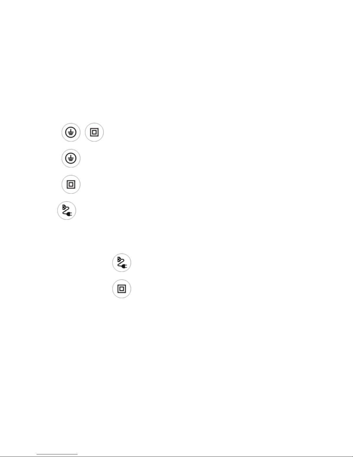
8.Warning Symbol
9.Unit Error
10.Readings and Cable Results
11.Leakage Current
12.Double Insulated / Class II Test
13.Class I Test
Page 6
5
Class I Test Button + Zero/Null Selection
Class II Test Button + 250V Insulation Selection
IEC / Cable Test Button +30m Long Lead Selection
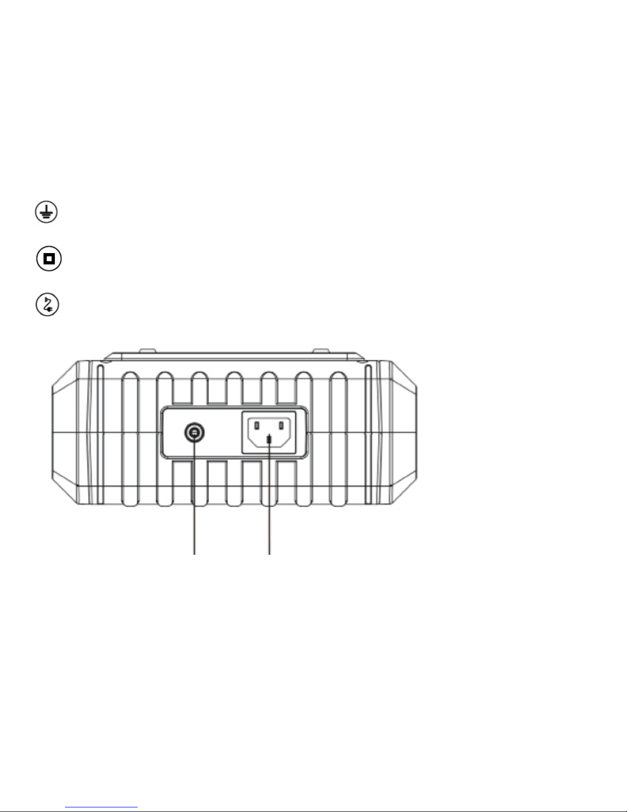
Earth Probe Mains / IEC testing
Page 7
6
Front Panel Operation
1: Press
+ button to Power on / Power Off.
2: Press button when testing a CLASS I Appliance.
3: Press
button when testing a CLASS II Appliance.
4: Press button when performing Cord / Extension Lead testing.
Advance Features
5: Press and hold the
button this will set the tester into Long Lead Mode.
6. Press and hold the
button to activate 250v insulation test.
You can exit the above advanced features by turning the unit off and back on.
Page 8

7
Before Testing - Zero the Earth Bond Test Lead!
Plug the earth probe into the rear of the unit and connect it to the earth nulling
adapter. Plug the earth nulling adapter into the front panel earth socket to
complete the circuit.
Press and hold the
button for 5 seconds to zero the earth bond reading
using the earth bond lead and the nulling adapter together in the front test socket.
This will null the earth reading of the test lead and “GOOD” will be displayed once
complete. It is good practice to do this once prior to carrying out testing.
Auto Switch Off
The unit will automatically switch off after approximately 2 minutes if no buttons
are pressed.
Testing a Class 1 Appliance
Plug the appliance into the UT528/528AU panel main socket. Plug the earth test lead into
the socket on the UT528/528AU end panel. Connect the earth crocodile clip to an
Page 9

8
exposed metal part on the appliance as shown in Diagram 3.
1. Earth / Protective Conductor Test
Press the Class 1 test button
to start the test. The earth resistance test will
begin.
Page 10

9
If the earth resistance measured is greater than 0.2Ω, the meter will display “×
Rpe”, which is a FAIL. If this occurs, re- check the connections between the pin of
the plug to the bodywork of the appliance and that the crocodile clip is attached to
clean earthed metalwork on the appliance (try attaching the clip to an alternative
piece of metalwork). If all connections are ok the appliance earth connection may
be faulty.
The PASS mark for the earth bond test is 0.2 Ω for a Class 1 appliance.
If the reading is less than 0.2 Ω, the meter will display “√ Rpe”, which is a PASS.
The unit will then automatically attempt to proceed to the insulation test. If it
detects that the appliance’s power switch is in the ON position it will carry out the
insulation test automatically.
If this is not detected the unit will display a flashing
symbol and also “LO
LOAD”. Press the button to proceed to the insulation test.
Page 11

10
2. Insulation Resistance Test
Before the unit carries out the insulation test it will attempt to check that the
connected appliance’s power switch is in the on position.
If it detects that the appliance switch is in the on position it will automatically
carry out the insulation test.
Please note: most electronic appliances will have electronic ‘on/off’ switches
and even though they are switched on the “Check Connections” message will
still appear.
If the measured resistance is greater than 1MΩ, the meter will display “√
Riso” as a PASS rating.
If the insulation of the appliance is less than 1MΩ, it will display “× Riso” as a
FAIL rating.
Leakage Test
3. After the unit has completed the insulation test it will automatically proceed to
the leakage test.
Page 12

UT528/528AU
UT528/528AU
Page 13

12
Class 2 Pre-Check
If the unit detects that the appliance appears to be Class 1 as it detects an
earth connection (possibly as a result of a connected earth clip) it will display
a flashing
symbol and you will be prevented from carrying out the Class
2 test. Test the appliance instead using the Class 1 test.
Insulation Resistance Test – Class 2 Appliance
Before the unit carries out the insulation test the unit will attempt to check to
Page 14

13
see if the appliance is in the on position.
If it detects that the appliance switch is in the “OFF” position it will wait and
display a flashing
symbol.
If you are sure that the appliance is switched on press the
button again
to start the test.
Please note: most electronic appliances will have electronic ‘on/off’ switches
and even though they are switched on the flashing
will still appear.
If the measured resistance is greater than 2MΩ, the meter will display “√
Riso” as a PASS rating.
If the insulation of the appliance is less than 2MΩ, it will display “× Riso” as a
FAIL rating.
Page 15

14
Leakage Test
5. After the unit has completed the insulation test it will automatically proceed to
the leakage test.
If the measured leakage is less than 0.25mA, the meter will display “√ ILeak”
as a PASS rating.
If the measured leakage is greater than 0.25mA, it will display “× ILeak” as a
FAIL.
Final Result - Class 2
After the above tests are completed, the meter will indicate whether the
appliance has Passed or Failed the Class 2 test.
Testing an IEC Lead / Extension Lead / Cord Test
Plug the mains lead under test into the socket and the front panel mains socket
on the unit as shown in Diagram 5.
Page 16

15
To Start the Cord Test Press
1. Earth Bond Test
The unit will carry out an earth bond test in the same manner as a Class 1
appliance. The Pass mark for this test is 0.2 Ω
2. Insulation Test
The unit will then carry out an insulation test as previously discussed in the
manual. The PASS Mark for this test is 2 MΩ.
Page 17

16
Please note: when testing Surge Protected Extension Leads this test may fail.
This is normal and a result of circuitry within the surge protection device.
3. Polarity Test
The polarity test is the final test to be carried out and will check that the cord
or extension is wired correctly. It will check for open circuit, short circuit or
Line / Neutral reversal.
If the Polarity is correct then the meter will display “√ Good”
If the Polarity test detects a fault, the meter will display “× Cross” or “× Open”
4. Overall Result
After the above measurements are completed, the meter will indicate
whether the measured appliance is compliant with the requirements of
cord testing with “PASS” or “FAIL”
Testing a Surge Protected Extension Lead or Appliance
When you press and hold the Class II appliance button for 5 seconds the tester
Page 18

17
will go into 250v insulation test mode and the screen will display ‘250 test’.
The insulation test voltage reduces from 500V to 250V to allow for the testing of
surge protected appliances and leads.
Please note: each insulation test carried out in this mode will be at 250V.
To exit this mode turn the tester off and back on.
Testing a Long Cable up to 30 metres
To test a long extension lead or cable ensure the tester is in long lead mode by
pressing and holding the
button for 5 seconds. To exit this mode turn off the
tester.
Checking a Mains Power Supply
The unit comes complete with a built in socket tester which will check to ensure
Page 19

18
that the socket is wired correctly.
Connect an IEC lead to the mains socket and plug this into the back of the meter
as shown in Diagram 6.
1)If the Live and Neutral in the socket wiring are reversed or there is a fault with
the protective earth connection this is indicated as “LN√, LE×, NE×”.
2)If there is a fault with the neutral connection this is indicated as “LN×, LE√,
NE×”
3)If the mains socket wiring is correct the display will show “LN√, LE √, NE√ ”
Page 20

0.2ohms
N/A N/A
N/A
Earth Continuity
Pass Limit& Accuracy
Test Current
Test Voltage
200mA minimum
5V nominal
±(5%+2)
±(5%+2)
±(5%+2)
Insulation Resistance
Pass Limit & Accuracy
Test Voltage
Test Current
Test Current
500V
40Vrms,50Hz AC
>1mA 500k
<2mA 1k
<5mA 2k
Leakage Current
Accuracy
Test Voltage
Test Current
Factory Default PASS/Fail Limits
Earth Continuity
Insulation Resistance
Leakage
Class I Class II Cord
UT528 UT528AU UT528 UT528AU UT528 UT528AU
1.0Mohms
0.75mA
1.0 Mohms 1.0 Mohms
2.0 Mohms 2.0 Mohms
0.25mA
1 ohm0.2 ohm
19
Page 21

Remarks (UT528AU Only):
Earth Continuity:class I ≤0.2Ω, Cord≤1 Ωis PASS.
Insulation Resistance ≥1.0MΩis PASS.
Leakage:class II ≤0.25mA is PASS.
Page 22

Page 23

 Loading...