

Page 1
ILLUSTRATED PARTS LIST
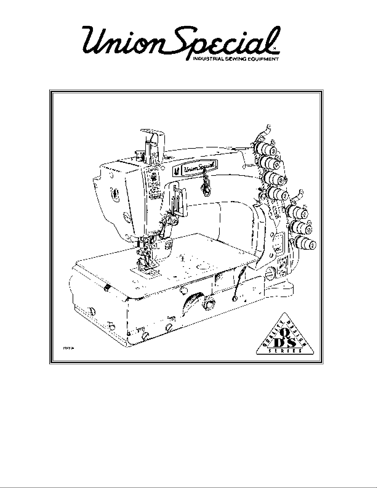
Three Needle, Wide Gauge, Plain Feed
Machines with Top Cover Thread
MANUAL NO. PT9511
STYLES
FS113L100MBV096
FS113L112MBV096
Page 2

Manual No. PT9511 Illustrated Parts List for FS100 Series Machines
Third Edition Copyright 1997
By
Union Special Corporation Rights Reserved In All Countries
Printed in U.S.A. May 1997
PREFACE
This parts manual has been prepared to assist you in locating individual parts or assemblies on FS100 Series machines.
It can be used in conjunction with Union Special Adjusting Manual IN9302.
It is the desire of Union Special that each machine run at its optimum performance. Parts listed in this manual are designed
specifically for your machine and are manufactured with the utmost precision to assure long lasting service.
This manual has been comprised on the basis of available information. Changes in design and/or improvements may
incorporate a slight modification of configuration in illustrations or part numbers.
On the following pages are illustrations and terminology used in describing the parts used on FS100 Series machines.
2
Page 3

SAFETY RULES
The sewing machines described in this instruction manual are prohibited from being put into service until it has been
ascertained that the sewing units, in which these sewing machines will be built-in have conformed with the EC Council
Directives (89/392/EEC, Annex II B).
1 . Before putting the machines described in this manual into service, carefully read the instructions. The starting of each
machine is only permitted after taking notice of the instructions and by qualified operators.
IMPORTANT! Before putting the machine into service, also read the safety rules and instruction from the motor supplier.
2 . Observe the national safety rules valid for your country.
3 . Each machine is only allowed to be used as foreseen. The foreseen use of the particular machine is described in paragraph
“STYLES OF MACHINES” of this instruction manual. Another use, going beyond the description, is not as foreseen.
4 . All safety devices must be in position when the machine is ready for work or in operation. Operation of the machine without
the appertaining safety devices is prohibited.
5 . Wear safety glasses.
6 . In case of machine conversions and changes all valid safety rules must be considered. Conversions and changes are made
at your own risk.
7 . The warning hints in the instructions are marked with one of these two symbols:
8 . For the following the machine has to be disconnected from the power supply by turning off the main switch or by pulling
out the main plug:
8. 1 For threading needle(s), looper, spreader etc.
8. 2 For replacing sewing parts such as needle, presser foot, throat plate, looper, spreader, feed dog, needle guard,
folder, fabric guide etc.
8 .3 When leaving the workplace and when the workplace is unattended.
8 .4 For maintenance work.
8. 5 When using clutch motors without actuation lock, wait until the motor is stopped totally.
9 . Maintenance, repair and conversion work (see item 8) must be done only by trained technicians or special skilled personnel
under consideration of the instructions.
10 . Any work on the electrical equipment must be done by an electrician or under direction and supervision of special skilled
personnel.
11 . Work on parts and equipment under electrical tension is not permitted. Permissible exceptions are described in the
applicable sections of standard sheet DIN VDE 0105.
12 . Before doing maintenance and repair work on the pneumatic equipment, the machine has to be disconnected from the
compressed air supply. In case of existing residual air pressure after disconnecting from compressed air supply (e.g.
pneumatic equipment with air tank), the pressure has to be removed by bleeding.
* Exceptions are only allowed for adjusting work and function checks done by special skilled personnel.
3
Page 4
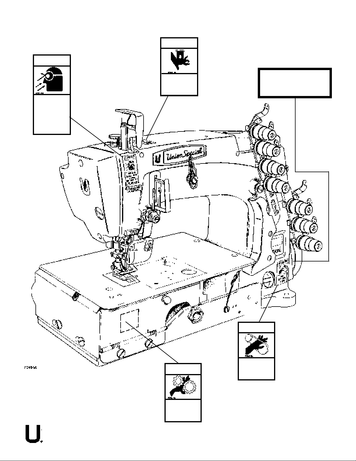
CAUTION
CAUTION AREAS
CAUTION
WEAR SAFETY
GLASSES, DO NOT
TAMPER WITH
SAFETY SHIELD.
USE WITHOUT
SHIELD MAY
CAUSE INJURY.
KEEP NEEDLE
BAR GUARD
IN PLACE
CAUTION
DO NOT OPERATE
MACHINE WITHOUT THIS
BELT GUARD IN PLACE
CAUTION
KEEP COVER
CLOSED DURING
OPERATION
4
CAUTION
KEEP
BELT GUARD
IN PLACE
Page 5
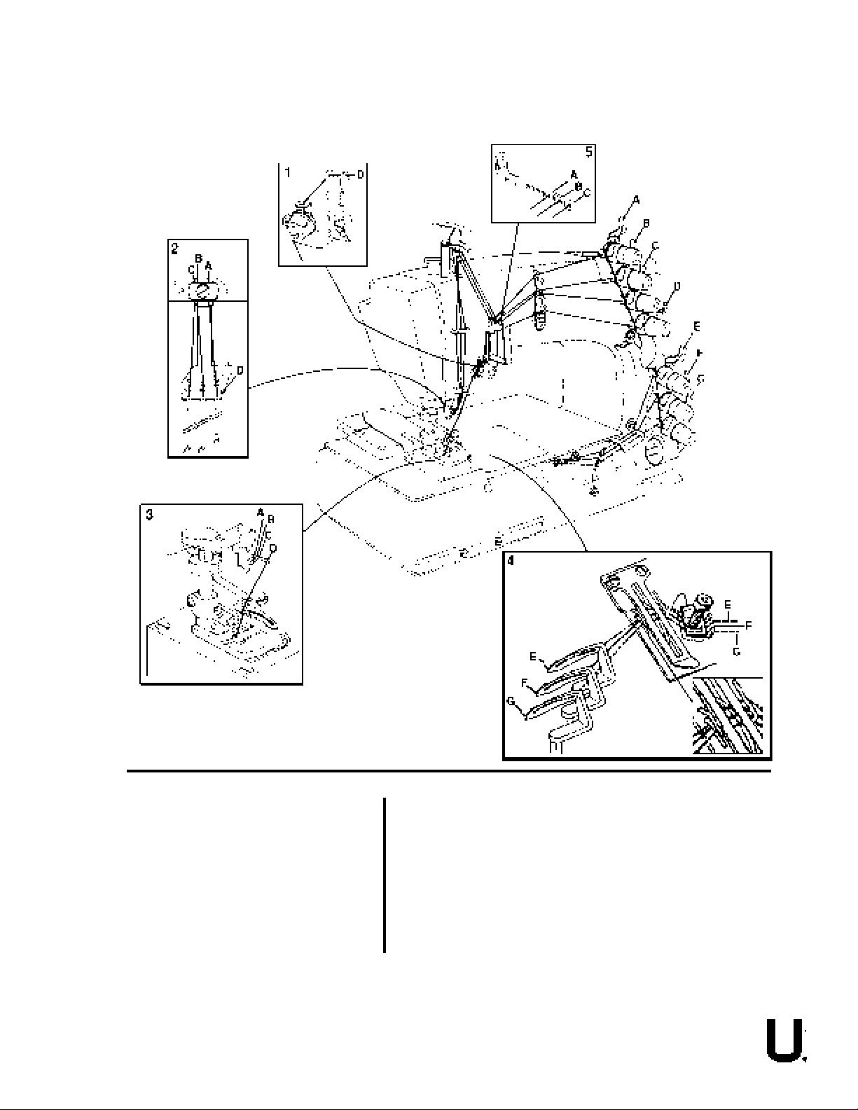
THREADING
A Right Needle Thread
B Middle Needle Thread
C Left Needle Thread
D Spreader Thread
E Rear/Right Looper Thread
F Middle Looper Thread
G Front/Left Looper Thread
1 Spreader Thread Take-Up & Nipper Area
2 Needle Head & Needle Thread Nipper Area
3 Sewing Area
4 Looper, Looper Thread Take-up & Nipper Area
5 Needle Lever Thread Eyelet Area
5
Page 6

CONTENTS
•PREFACE................................................................................................................................................................ 2
•SAFETY RULES....................................................................................................................................................... 3
•CAUTION AREAS ..................................................................................................................................................... 4
•THREADING ............................................................................................................................................................ 5
•IDENTIFICATION OF MACHINES .............................................................................................................................. 7
•MACHINE STYLES ................................................................................................................................................... 7
•NEEDLES ............................................................................................................................................................... 7
•TERMS ................................................................................................................................................................... 7
•ILLUSTRATIONS...................................................................................................................................................... 8
•IDENTIFYING PARTS ............................................................................................................................................... 8
EXPLODED VIEWS
•MISCELLANEOUS COVERS, GUARDS, THREAD GUIDES & CAST-OFF PLATE......................................................... 11
•MISCELLANEOUS COVERS, GUARDS, THREAD GUIDES & CAST-OFF PLATE (CONT.) ........................................... 13
•LUBRICATION SYSTEM & BUSHINGS ..................................................................................................................... 15
•CRANKSHAFT, NEEDLE LEVER, NEEDLE BAR & LOOPER DRIVE MAECHANISM ................................................... 1 7
•CRANKSHAFT, NEEDLE LEVER, NEEDLE BAR & LOOPER DRIVE MECHANISM (CONT.) ........................................ 1 9
•SPREADER MECHANISM DRIVE ................................................................................................................... 21
•LOOPER ROCKER & CONNECTING ROD ............................................................................................................... 23
•FEED MECHANISM, MAIN SHAFT & TAKE-UP ........................................................................................................ 25
•FEED MECHANISM, MAIN SHAFT & TAKE-UP (CONT.) ........................................................................................... 27
•PRESSER FOOT LIFTER LEVER............................................................................................................................. 29
•THREAD TENSION ASSEMBLY .............................................................................................................................. 31
•COVERS & MISCELLANEOUS PARTS .................................................................................................................... 33
•PRESSER FOOT, THROAT PLATE & FEED DOG .................................................................................................... 35
•CHAIN CUTTER ASSEMBLY FOR STYLE:
FS113L112MBV096 ............................................................................................................................................. 37
•SHUTTLE VALVE ASSEMBLY FOR STYLE:
FS113L112MBV096 ............................................................................................................................................. 39
•MUFFLER/ CHAIN RECOVERY SYSTEM FOR STYLE:
FS113L112MBV096 ............................................................................................................................................. 41
•TREADLE OPERATED AIR VALVE ASSEMBLY FOR STYLE:
FS113L112MBV096 ............................................................................................................................................. 43
•FILTER, REGULATOR, LUBRICATOR, GAUGE ASSEMBLY FOR STYLE:
FS113L112MBV096 ............................................................................................................................................. 45
•AIR CIRCUIT DIAGRAM FOR STYLE:
FS113L112MBV096 ............................................................................................................................................. 46
•NOTES ................................................................................................................................................................. 47
•ACCESSORIES ...................................................................................................................................................... 49
•NUMERICAL INDEX OF PARTS .............................................................................................................................. 50
•NUMERICAL INDEX OF PARTS .............................................................................................................................. 51
•NOTES ................................................................................................................................................................. 52
•NOTES ................................................................................................................................................................. 53
6
Page 7

IDENTIFICATION OF MACHINES
Each Union Special machine carries a style number, which on this class machine is stamped in the style plate affixed
to the right front of the machine.
The serial number is stamped in the casting at the right rear base of machine.
MACHINE STYLES
Advanced series, heavy duty flat bed machine. Three needles, three loopers, one spreader, one auxiliary spreader,
plain feed, enclosed automatic lubrication system. Maximum work space to right of needle bar 81/4" (210mm).
FS113L100MBV LAP-SEAMER: Three needle, top cover thread, plain feed machine - Typical application -
For pocket facing applications on medium to heavy weight denim. Seam specification
408LSbj-1 (Mod.). Standard Gauge Number 096 [3/8", 9.6 mm]. Maximum recommended
speed depending on application is 4500 R.P.M. Recommended needle 128 GS, size
125/049.
FS113L112MBV Same as style FS113L100MBV096 except fitted with a flat action (mounted on cloth plate),
compressed air operated chain cutter with venturi suction and chain disposal.
NEEDLES
Each needle has both a type and size number. The type number denotes the kind of shank, point, length, groove,
finish and other details. The size number, stamped on the needle shank, denotes the largest diameter of the blade
measured between the shank and the eye. Collectively, the type number and size number represent the complete
symbol which is given on the label of all needles packed and sold by Union Special.
TYPE DESCRIPTION
128 GS Short, double groove, struck groove, ball eye, spotted, undersize eye and grooves 27% of size of
needle, chromium plated - Sizes Available 090/036,100/040,110/044, 125/049, 140/054.
When changing the needle, make sure it is fully inserted in the needle head before the screw is tightened.
To have needles promptly and accurately filled, an empty package, a needle sample, or the type and size number
should be forwarded. Use the description on the label. A complete order should read as follows: "100 needles,
type 121 GBS, size 125/049".
TERMS
Prices are net cash and subject to change without notice. All shipments are forwarded F.O.B. shipping point. A
charge is made to cover postage and insurance.
7
Page 8

ILLUSTRATIONS
This manual has been arranged to simplify ordering repair parts. Exploded views of various sections of the
mechanism are shown so that the parts may be seen in their actual position in the machine. On the page opposite
the illustration will be found a listing of the parts with their part numbers, description and the number of pieces
required in the particular view being shown.
Numbers in the first column are reference numbers only, and merely indicate the position of the part in the
illustration. The reference number should never be used in ordering parts. Always use the part number listed in
the second column.
Component parts of sub-assemblies which can be furnished for repairs are indicated by indenting their descriptions
under the description of the main sub-assembly. As an example refer to the following text.
9. 29126EC Upper Looper Drive Shaft Assembly ........................................ 1
10. 22503F Screw ............................................................................. 1
11. 39543E Cam Follower Locking Clamp ............................................. 1
When a part is common to all machines covered in this manual, no specific usage will be mentioned in the description.
However, when the parts for the various machines are not the same, the specific usage will be mentioned in the
description and, if necessary, the difference will be shown in the illustration.
A numerical index of all the parts shown in this manual is located at the back. This will facilitate locating the
illustration and description when only a part number is known.
IDENTIFYING PARTS
Where the construction permits, each part is stamped with its part number. On some of the smaller parts and on
those where construction does not permit, an identification letter is stamped in, to distinguish the part from similar
ones.
PLEASE NOTE: Part numbers represent the same part, regardless of which manual they appear in. On all orders
please include part number, name and style of machine for which the part was ordered.
* For optimum performance, use only genuine Union Special replacement parts.
8
Page 9
EXPLODED
VIEWS ...
Page 10
8
10
9
11
12
70
71
7
6
5
4
3
80
79
50
52
44
42
43
51
41
40
62
63
64
68
70
69
2
76
73
75
74
71
55
56
57
58
1
72
77
78
53
54
59
60
61
13
17
48
49
48
47
46
45
39
38
14
15
16
17
18
19
22
20
21
20
21
23
24
81
87
83
84
82
85
88
86
89
90
65
66
24
37
67
29
28
27
30
32
31
35
36
33
34
25
26
10
Page 11

MISCELLANEOUS COVERS, GUARDS, THREAD GUIDES & CAST-OFF PLATE
Ref.
No.
1.
2.
3.
4.
5.
6.
7.
8.
9.
10.
11.
12.
13.
14.
15.
16.
17.
18.
19.
20.
21.
22.
23.
24.
25.
26.
27.
28.
29.
30.
31.
32.
33.
34.
35.
36.
37.
38.
39.
40.
41.
42.
43.
44.
45.
46.
47.
48.
49.
50.
51.
Part No.
56382Y
56382AB
56382AV
56382J
22829
56382AA
22848
22524
56382AU
22548
56382D
56382AX
660-1002
22541C
57782M
56382AY
90
56382AC
22539S
80557
22839C
21375CE
22829
98A
158A
56391B
51457B
52804A
28
51959D
51959K
51959B
51492
51959J
22569C
69H
52958G
22585C
57858C
57892H
57892C5
80665F
57892J
57844
22848
20
51758
539
22889H
57882J
22585C
Description
Block, for oil drip plate ......................................................................
Oil Drip Plate ....................................................................................
Gasket, for looper drive shaft cover .....................................................
Cover, for looper drive shaft ................................................................
Screw, for looper drive shaft cover ........................................................
Oil Reservoir Cover, back .....................................................................
Screw, for oil reservoir cover, back .....................................................
Screw, for oil drip plate .....................................................................
Gasket, for oil reservoir cover, back ......................................................
Screw, for crank chamber cover, lower ..................................................
Crank Chamber Cover, lower ...............................................................
Gasket, for crank chamber cover, lower .................................................
Plug, for crank chamber cover, upper ....................................................
Screw, for crank chamber cover, upper ..................................................
Crank Chamber Cover, upper ...............................................................
Gasket, for crank chamber cover, upper ..................................................
Screw, for bearing oiler assembly ..........................................................
Bearing Oiler Assembly .......................................................................
Plug Screw, for bed ............................................................................
Washer, for tension assembly (see page 31) ............................................
Screw, for tension assembly (see page 31) .............................................
Belt Guard .......................................................................................
Screw, for belt guard ..........................................................................
Screw, for looper guard thread eyelet ....................................................
Looper Thread Eyelet ..........................................................................
Looper Thread Guard ..........................................................................................
Cast-Off Plate .....................................................................................................
Hold Down Plate, for looper thread ......................................................................
Screw, for hold down plate ..................................................................................
Tension Nut ......................................................................................................
Tension Spring ................................................................................
Tension Disc ..................................................................................
Tension Post ..................................................................................
Looper Thread Guide .........................................................................
Screw, for support plate ...................................................................
Washer, for support plate screw .........................................................
Eyelet, for looper thread ...................................................................
Screw, for eyelet ............................................................................
Eyelet, looper thread ......................................................................
Nut, for spreader thread post ..............................................................
Spreader Tension Spring ...................................................................
Disc, for tension post .........................................................................
Spreader Tension Post .....................................................................
Spreader Thread Guide .....................................................................
Screw, for thread eyelets ................................................................
Washer, for thread eyelets ................................................................
Eyelet, spreader thread ...................................................................
Eyelet, needle thread ....................................................................
Adapter Screw .................................................................................
Guard, for needle lever eyelet .............................................................
Screw, for needle lever eyelet ............................................................
Amt.
Req.
1
1
1
1
2
1
9
2
1
4
1
1
1
4
1
1
2
1
1
2
2
1
2
3
1
1
1
1
2
1
1
2
1
1
2
2
1
1
1
1
1
2
1
1
1
1
1
2
1
1
1
52. thru 88. See following page.
11
Page 12
8
10
9
11
12
70
71
7
6
5
4
3
80
79
50
52
44
42
43
51
41
40
62
63
64
68
70
69
2
76
73
75
74
71
55
56
57
58
1
72
77
78
53
54
59
60
61
13
17
48
49
48
47
46
45
39
38
14
15
16
17
18
19
22
20
21
20
21
23
24
81
87
83
84
82
85
88
86
89
90
12
65
66
24
37
67
29
28
27
30
32
31
35
36
33
34
25
26
Page 13

MISCELLANEUOS COVERS, GUARDS, THREAD GUIDES & CAST-OFF PLATE (CONT.)
Ref.
No.
Part No.
1. thru 51. See preceding page.
57858B
52.
95
53.
57844C
54.
34758
55.
57858A
56.
43296A
57.
22797
58.
57WB
59.
15438C
60.
57WD
61.
34844D
62.
28
63.
77
64.
57845E
65.
22585A
66.
22513B
67.
57882K
68.
22539AB
69.
22541C
70.
22851D
71.
57882P
72.
22564B
73.
34831C
74.
22539AA
75.
22585A
76.
56470
77.
33795
78.
22894E
79.
660-617
80.
81.
99682XF
82.
14077
83.
99683CN
84.
99682XC2
85.
95978
86.
56525F
87.
99696A
88.
22758E
89.
22766
90.
56525E
Description
Eyelet, spreader thread ...............................................................................
Set Screw .......................................................................................
Eyelet Mounting Plate .........................................................................
Needle Thread Guide ..........................................................................
Thread Guide Spring ..........................................................................
Base Nipper Spring ...........................................................................
Screw ...........................................................................................
Nipper Tension Plate ..........................................................................
Nipper Spring ..................................................................................
Screw, for nipper spring ....................................................................
Spreader Thread Guide Mounting Plate ...................................................
Screw ...................................................................................
Screw ...................................................................................
Spreader Thread Guide ...................................................................
Screw, for spreader thread mounting plate ..........................................
Screw , for spreader thread mounting plate ...........................................
Head Cover .....................................................................................
Plug Screw, for head cover .....................................................................
Screw, for head cover ...................................................................
Screw, for head cover .......................................................................
Gasket, for head cover ......................................................................
Screw, for guide plate ......................................................................
Guide Plate .................................................................................
Plug Screw, for bed ..........................................................................
Screw, for eyelet guard .................................................................
Needle Thread Take-Up ..................................................................
Guard, for needle thread eyelet ..........................................................
Screw, for needle lever stud ...........................................................
Gasket, for needle lever eyelet ........................................................
Needle Break Guard Assembly ..........................................................
Nut ......................................................................................
Mounting Plate .......................................................................
Bracket ................................................................................
Spring Washer ........................................................................
Spacer .................................................................................
Shield ....................................................................................
Shoulder Screw ........................................................................
Screw .....................................................................................
Sewing Guard ..................................................................................
Amt.
Req.
1
1
1
1
1
1
1
1
1
1
1
1
1
1
1
1
1
1
2
2
1
4
2
1
1
1
1
2
1
1
1
1
1
1
1
1
1
2
1
13
Page 14
3
2
7
9
8
4
1
41
5
5
9
8
6
7
7
7
13
12
23
36
40
39
22
37
34
32
23
38
35
33
19
24
25
19
27
18
26
10
30
31
17
29
28
11
14
15
16
21
20
14
Page 15

LUBRICATION SYSTEM & BUSHINGS
Ref.
No.
1.
2.
3.
4.
5.
6.
7.
8.
9.
10.
11.
12.
13.
14.
15.
16.
17.
18.
19.
20.
21.
22.
23.
24.
25.
26.
27.
28.
29.
30.
31.
32.
33.
34.
35.
36.
37.
38.
39.
40.
41.
Part No.
59493A
660-230
258A
666-214
57849
CL21
56390H
56390J
660-665
52883R
21657X
22569B
57890B
56390E
22539R
51-902BLK
999-216K
52942AB
50-895BLK
56393P
666-259
56390
57836B
57842B
56190
35897BV
56393Q
56390G
57893
57893A
666-214
660-739
51257AA
57847B
57854
57893C
6-67-125
56393W
22585A
660-406
51154E
Description
Base Oil Pump Assembly ......................................................................
Gasket .......................................................................................
Nut ...........................................................................................
Felt Intake ..................................................................................
Bushing, for spreader rocker shaft .........................................................
Oil Wick ...........................................................................................
Thrust Washer ..................................................................................
Pilot Ring .........................................................................................
Needle Thrust Bearing ........................................................................
Bushing, for presser foot lifter ..............................................................
Release Bushing ................................................................................
Screw, for crankshaft bushing housing ...................................................
Crankshaft Bushing Housing .............................................................
Gasket, housing ................................................................................
Oil Drain Plug ...............................................................................
Oil Sight Gauge ...............................................................................
Plug, for bed ..................................................................................
Bushing, for looper drive lever shaft, front .............................................
Bushing, for looper rocker shaft ............................................................
Felt, base, front ................................................................................
Felt ...............................................................................................
Main Shaft Bushing, left ....................................................................
Bushing, for feed rocker shaft ..............................................................
Bushing, for looper drive shaft, rear ......................................................
Main Shaft Bushing, middle ..................................................................
Filter, for main shaft bushing ...............................................................
Felt, base, rear ................................................................................
Main Shaft Bushing, right ....................................................................
Oil Pump Assembly, head ...................................................................
Oil Tube ....................................................................................
Felt Intake .................................................................................
Oil Seal ..........................................................................................
Presser Bar Bushing ...........................................................................
Spreader Bushing .............................................................................
Needle Bar Bushing, lower ..................................................................
Oil Tube .........................................................................................
Felt ..........................................................................................
Felt, Oil Attraction ............................................................................
Screw, for clamp ...............................................................................
Clamp, for oil tube .............................................................................
Needle Bar Bushing, upper ..................................................................
Amt.
Req.
1
1
1
1
2
1
4
2
2
1
1
3
1
1
1
1
1
2
2
1
1
1
2
1
1
1
1
1
1
1
1
1
1
1
1
1
1
1
1
1
1
15
Page 16
61
62
60
63
TORQUE:
24
22
19-21 in. lbs.
2.1-2.3 Nm
25
TORQUE:
38 in. lbs.
(4.3 Nm)
27
26
TORQUE:
24-26 in. lbs.
(2.7-2.9 Nm)
28
29
32
31
32
30
1
2
3
4
5
6
7
10
11
12
13
14
9
16
17
18
15
No. 3
As viewed
from the side
8
19
23
20
21
TORQUE:
19-21 in. lbs.
2.1-2.3 Nm
42
43
43
42
40
45
46
44
47
48
TORQUE:
26-28 in. lbs.
2.9-3.2 Nm
49
50
52
53
51
57
58
54
55
56
NOTE:
Cut-out in Ref. No.
38 & 39 to be up
when assembling
39
59
33
34
35
38
41
See "Aligning main shaft to
crankshaft" in adjusting
manual for torque sequence
36
37
TORQUE:
Ref. No. 41, 42, 43
19-21 in. lbs.
2.1-2.3 Nm
NOTE:
16
Page 17

CRANKSHAFT, NEEDLE LEVER, NEEDLE BAR & LOOPER DRIVE MECHANISM
Ref.
No.
1.
2.
3.
4.
5.
6.
7.
8.
9.
10.
11.
12.
13.
14.
15.
16.
17.
18.
19.
20.
21.
22.
23.
24.
25.
26.
27.
28.
29.
30.
Part No.
22586R
51250V
51250D
56382AK
660-625
56350J
56350K
29348AF
56315A
56350G
77
56354D
51254K
22562A
22564
660-215
52336A
WO3
56350D
660-625
22768
54458-9
29105BC
22559G
51216N
51216P
56316
61321L
22574
57821A
Description
Screw, for needle lever assembly ...........................................................
Washer ...........................................................................................
Washer ...........................................................................................
Gasket, for thrust collar ......................................................................
"O" Ring ...........................................................................................
Collar .............................................................................................
Torlon Washer ..................................................................................
Needle Lever Assembly .......................................................................
Needle Lever ...............................................................................
Bushing ................................................................................
Screw ........................................................................................
Link, for needle bar .......................................................................
Needle Bar Connection ..................................................................
Screw .................................................................................
Screw ........................................................................................
Retaining Ring .............................................................................
Link Pin ......................................................................................
Oil Wick ................................................................................
Needle Lever Stud ......................................................................
"O" Ring ........................................................................................
Screw, for needle lever eyelet ................................................................
Needle Lever Thread Eyelet ...............................................................
Ball Joint, for needle lever ...................................................................
Screw, for ball joint ............................................................................
Washer, for ball joint ..........................................................................
Nut, for ball joint ................................................................................
Needle Lever Connecting Rod ..............................................................
Retaining Plate ..................................................................................
Screw, for handwheel ..........................................................................
Handwheel .......................................................................................
Amt.
Req.
1
1
1
1
1
1
2
1
1
1
1
1
1
1
1
4
2
2
1
1
1
1
1
2
1
1
2
1
3
1
31. thru 61. See following page.
17
Page 18

62
61
63
60
TORQUE:
24
22
19-21 in. lbs.
2.1-2.3 Nm
25
TORQUE:
38 in. lbs.
(4.3 Nm)
27
26
TORQUE:
24-26 in. lbs.
(2.7-2.9 Nm)
28
29
32
31
32
30
1
2
3
4
5
6
7
10
11
12
13
14
9
16
17
18
15
No. 3
As viewed
from the
side
8
19
23
20
21
TORQUE:
19-21 in. lbs.
2.1-2.3 Nm
42
43
43
42
40
45
46
44
47
48
TORQUE:
26-28 in. lbs.
2.9-3.2 Nm
49
50
52
53
51
57
58
54
55
56
NOTE:
Cut-out in Ref. No.
38 & 39 to be up
when assembling
39
59
33
34
35
38
41
See "Aligning main shaft to
crankshaft" in adjusting
manual for torque sequence
36
37
TORQUE:
Ref. No. 41, 42, 43
19-21 in. lbs.
2.1-2.3 Nm
NOTE:
18
Page 19

CRANKSHAFT, NEEDLE LEVER, NEEDLE BAR & LOOPER DRIVE MECHANISM (CONT.)
Ref.
No.
Part No.
1. thru 30. See preceding page.
31.
56321R
32.
22894AB
33.
660-202
34.
29476PC
35.
51216M
36.
56316C
37.
12934A
38.
57893
39.
59493A
40.
56343F
41.
22653L8
42.
22894C
43.
22894D
44.
29105AK
45.
22587K
46.
56343C
47.
56343E
48.
22559A
49.
52942AF
50.
34342J
51.
22652A12
52.
57849C
53.
660-202
54.
56390H
55.
52951C
56.
56342K
57.
22882C
58.
51242M
59.
CL21
60.
31117A
61.
27-435BLK
62.
56958A
63.
22768
Description
Pulley .........................................................................................
Screw .......................................................................................
"O" Ring ...........................................................................................
Crankshaft Assembly .......................................................................
Needle Bearing ..........................................................................
Connecting Rod Guide ........................................................................
Nut, for connecting rod guide ................................................................
Oil Pump Assembly, head (see page 15, ref. no. 29) ......................................
Oil Pump Assembly, base (see page 15, ref. no. 1) .......................................
Coupling, for looper drive lever .............................................................
Screw, for looper drive lever coupling ..............................................
Set Screw, for looper drive lever coupling ...............................................
Spot Screw, for looper drive lever coupling ..............................................
Looper Lever Crank Assembly ...............................................................
Screw ......................................................................................
Ball Joint Guide ............................................................................
Oil Splasher ................................................................................
Screw .......................................................................................
Looper Drive Lever Rocker Shaft ............................................................
Binder Clamp ...................................................................................
Screw .....................................................................................
Thrust Washer ..................................................................................
"O" Ring ...........................................................................................
Washer ...........................................................................................
Thrust Washer ..................................................................................
Looper Drive Lever ......................................................................................
Screw ..........................................................................................................
Washer .........................................................................................................
Oil Wick .......................................................................................................
Needle Bar .......................................................................................................
Washer, for needle bar thread eyelet .............................................................
Needle Bar Thread Eyelet ...........................................................................
Screw, for needle bar thread eyelet ..............................................................
Amt.
Req.
1
2
1
1
28
1
1
1
1
2
2
2
2
1
2
1
1
2
1
1
1
1
1
1
1
1
1
1
1
1
1
1
1
19
Page 20

27
28
30
26
22
29
26
25
24
23
22
31
21
18
17
19
20
13
15
16
14
9
11
12
11
10
TORQUE:
24-26 in. lbs.
(2.7-2.9 Nm)
34
33
36
35
39
38
37
TORQUE:
19-21 in. lbs.
2.1-2.3 Nm
32
8
TORQUE:
19-21 in. lbs.
2.1-2.3 Nm
40
7
6
5
4
6
45
44
41
1
2
43
3
42
46
47
20
Page 21

SPREADER MECHANISM DRIVE
Ref.
No.
1.
2.
3.
4.
5.
6.
7.
8.
9.
10.
11.
12.
13.
14.
15.
16.
17.
18.
19.
20.
21.
22.
23.
24.
25.
26.
27.
28.
29.
30.
31.
32.
33.
34.
35.
36.
37.
38.
39.
40.
41.
42.
43.
44.
45.
46.
47.
Part No.
57845D
22738B
57845F
57845G
77
94
41332J
34847A
WO3
57848E
22729
15430L
-
WI30
93
57835M
20
18
57849A
55235D
6042A
55235E
CL35
999-232
52849
57847
95
57849C
57849D
55235E
6042A
55235D
22559G
29105BD
52952C
55235D
6042A
55235E
18
HA20A
57852B
52916
29126CR
22597A
52951B
660-246
52951C
52947A
22587H
Description
Spreader ......................................................................................
Screw ......................................................................................
Auxiliary Spreader ..............................................................................
Spreader Holder ................................................................................
Screw ......................................................................................
Screw .......................................................................................
Thrust Washer ...................................................................................
Spreader Holder Drive Shaft ................................................................
Oil Wick .....................................................................................
Carrier Connecting Rod Assembly ..........................................................
Screw .......................................................................................
Oil Pad .................................................................................
Oil Wick ..................................................................................
Screw ......................................................................................
Washer, ball .....................................................................................
Washer, for carrier connecting rod assembly .......................................
Nut, for carrier connecting rod assembly ..............................................
Spreader Rocker Shaft Arm .................................................................
Locking Stud .............................................................................
Washer .....................................................................................
Nut ............................................................................................................
Wick, for spreader rocker shaft collar ...........................................................
"O" Ring, for spreader rocker shaft ........................................................
Spreader Rocker Shaft ........................................................................
Crankshaft Thrust Collar .....................................................................
Screw ........................................................................................
Washer ...........................................................................................
Spreader Rocker Shaft Collar, inner ........................................................
Nut ...........................................................................................
Washer ......................................................................................
Locking Stud ..............................................................................
Screw, for spreader connecting rod ball joint, upper ...................................
Spreader Connecting Rod Ball Joint, upper ...............................................
Segment Lever ..................................................................................
Locking Stud ..............................................................................
Washer .....................................................................................
Nut ..........................................................................................
Nut, for spreader connecting rod ball joint ................................................
Washer ...........................................................................................
Spacer ............................................................................................
Connecting Rod .................................................................................
Spreader Drive Eccentric Assembly ......................................................
Screw ........................................................................................
Retaining Washer ........................................................................
Retaining Ring .............................................................................
Spacer Washer .................................................................................
Counterweight ..................................................................................
Screw, for counterweight ....................................................................
Amt.
Req.
1
2
1
1
2
2
2
1
1
1
4
1
1
1
1
1
1
1
1
1
1
1
2
1
2
2
2
1
1
1
1
2
1
1
1
1
1
1
1
1
2
1
2
1
1
1
1
2
21
Page 22

10
17
18
19
11
12
13
14
15
1
16
45
46
22
20
21
26
35
34
38
37
36
33
3
4
5
9
8
2
1
23
47
42
44
40
41
42
39
43
44
48
49
TORQUE:
55 in. lbs.
(6.2 Nm)
32
6
7
25
27
29
TORQUE:
19-21 in. lbs.
2.1-2.3 Nm
28
24
29
30
31
22
Page 23

LOOPER ROCKER & CONNECTING ROD
Ref.
No.
1.
2.
3.
4.
5.
6.
7.
8.
9.
10.
11.
12.
13.
14.
15.
16.
17.
18.
19.
20.
21.
22.
23.
24.
25.
26.
27.
28.
29.
30.
31.
32.
33.
34.
35.
36.
37.
38.
39.
40.
41.
42.
43.
44.
45.
46.
47.
48.
49.
Part No.
51244L
51246
56344C
98
719
96
22874
51236J
56344B
CO67E
WO3
56344
55244G
51244N
51216N
18
56342K
22882C
20
51908C24
51909E24
51909F24
18
29192AH
51745
56913B
22565
15465F
88
258
22829
56393J
87U
57841
22729C
269
51240D
18
56341N
56341V
56341T
660-210
56341W
660-310
56341P
56341S
56341R
20
627
Description
Thrust Washer ..................................................................................
Nut, for looper rocker assembly ............................................................
Looper Rocker Frame ..........................................................................
Set Screw ...................................................................................
Stop Screw .................................................................................
Spot Screw, for looper rocker frame ......................................................
Lock Screw, for looper rocker frame ....................................................
Connecting Pin ..................................................................................
Looper Rocker Arm ............................................................................
Cork Plug, for looper rocker shaft .........................................................
Wool Yarn, for looper rocker shaft ......................................................
Looper Rocker Shaft ...........................................................................
Stud, for looper rocker shaft collar ........................................................
Looper Rocker Shaft Collar ...................................................................
Washer, for shaft stud .......................................................................
Nut, for shaft stud ..............................................................................
Looper Drive Lever ............................................................................
Screw .......................................................................................
Washer ......................................................................................
Front Looper ...................................................................................
Middle Looper ..................................................................................
Rear Looper ....................................................................................
Nut ...............................................................................................
Looper Rocker Assembly ....................................................................
Stud Looper Rocker Cone ................................................................
Looper Rocker .............................................................................
Set Screw ...........................................................................
Cone .........................................................................................
Set Screw ............................................................................
Nut ........................................................................................
Screw .....................................................................................
Ball Joint Oiler ..................................................................................
Screw , for ball joint oiler ..................................................................
Looper Connecting Rod Ball Joint .........................................................
Screw .......................................................................................
Nut, left hand thread ...........................................................................
Looper Connecting Rod .......................................................................
Nut, right hand thread .........................................................................
Looper Connecting Rod Assembly, right .............................................
Spring ...................................................................................
Pin .......................................................................................
Retaining Ring .............................................................................
Pin ...........................................................................................
Retaining Ring .........................................................................
Looper Connecting Rod .............................................................
Lever .....................................................................................
Housing ....................................................................................
Washer ...........................................................................................
Screw ...........................................................................................
Amt.
Req.
2
1
1
1
1
1
1
1
1
1
1
1
1
1
1
1
1
1
1
1
1
1
1
1
1
1
3
1
2
1
1
1
1
1
2
1
1
1
1
1
1
2
1
2
1
1
1
1
1
23
Page 24

2
5
1
3
7
4
8
6
4
2
1
8
18
12
13
14
11
10
9
18
19
20
25
24
23
15
16
17
22
21
30
26
27
28
29
34
33
32
TORQUE:
19-21in. lbs.
(2.1-2.3Nm)
31
36
49
52
51
50
56
57
48
TORQUE:
55 in. lbs.
(6.2 Nm)
47
53
46
55
54
45
46
44
43
24
42
41
40
TORQUE:
19-21in. lbs.
(2.1-2.3Nm)
38
36
35
39
37
Page 25

FEED MECHANISM, MAIN SHAFT & TAKE-UP
Ref.
No.
1.
2.
3.
4.
5.
6.
7.
8.
9.
10.
11.
12.
13.
14.
15.
16.
17.
18.
19.
20.
21.
22.
23.
24.
25.
26.
27.
28.
29.
30.
Part No.
660-1009
56384
56335B
22651CD4
56334B
56335L
56335D
98
41391
660-438
56334N
22651CB4
22637P24
258A
6042A
22863C
56334L
61341J
22834A
- - - - - 51236J
WO3
22528
56525D
22801
22875H
61434G
56122A
56322B
22891B
Description
Needle Bearing ...............................................................................
Seal ...............................................................................................
Feed Rocker .....................................................................................
Screw .......................................................................................
Feed Bar Shaft ..................................................................................
Feed Rocker Shaft ..............................................................................
Feed Rocker Shaft Collar .....................................................................
Screw ........................................................................................
Feed Rocker Shaft Thrust Washer ...........................................................
Retaining Ring ...................................................................................
Feed Bar Assembly .............................................................................
Screw ........................................................................................
Feed Dog Height Adjusting Screw ......................................................
Nut ...........................................................................................
Washer, for feed dog holder ..........................................................
Feed Dog Holder Adjusting Screw .....................................................
Feed Dog Holder ..........................................................................
Feed Bar Washer ................................................................................
Needle Guard Adjusting Screw .............................................................
Feed Dog (See Page 35) ........................................................................
Link Pin ...........................................................................................
Oil Wick ............................................................................
Screw, for feed dog ............................................................................
Needle Guard ...................................................................................
Screw .....................................................................................
Screw, for needle guard ......................................................................
Washer ..........................................................................................
Main Shaft ......................................................................................
Gasket .....................................................................................
Oil Flow Regulating Screw ...........................................................
Amt.
Req.
2
2
1
2
1
1
1
2
1
1
1
1
1
1
1
1
1
2
2
1
1
1
1
1
1
1
1
1
1
1
31. thru 57. See following page.
25
Page 26

2
5
1
3
7
4
8
6
4
2
1
8
18
12
13
14
11
10
9
18
19
20
25
24
23
15
16
17
22
21
30
26
27
28
29
34
33
32
TORQUE:
19-21in. lbs.
(2.1-2.3Nm)
31
36
49
51
52
56
50
57
48
TORQUE:
55 in. lbs.
(6.2 Nm)
47
53
46
55
54
45
46
44
43
26
42
41
40
TORQUE:
19-21in. lbs.
(2.1-2.3Nm)
38
36
35
39
37
Page 27

FEED MECHANISM, MAIN SHAFT & TAKE-UP (CONT.)
Ref.
No.
Part No.
1. thru 30. See preceding page.
31.
29476NM080
32.
22894AA
33.
77
34.
39543N
35.
56323B
36.
22580D
37.
29476NM062
38.
22894AA
39.
77
40.
56336D
41.
660-269B
42.
22543A
43.
56336
44.
22798C
45.
56322C
46.
22525A
47.
21657E
48.
269
49.
56335S
50.
55235D
51.
6042A
52.
55235E
53.
77
54.
56336K
55.
56336C
56.
51236J
57.
WO3
Description
Feed Lift Eccentric Assembly, .080", (2.03 mm) throw ..............................
Set Screw ...................................................................................
Screw .......................................................................................
Thrust Washer, for feed bar ................................................................
Looper Thread Take-Up .......................................................................
Set Screw ...............................................................................
Looper Avoid Eccentric Assembly, .062", (1.58 mm) throw ..........................
Set Screw ..................................................................................
Screw ........................................................................................
Feed Crank Stud Insert .......................................................................
Quad Ring ........................................................................................
Stitch Regulating Screw ......................................................................
Feed Crank Stud, marked "A" ................................................................
Screw .............................................................................................
Main Shaft Head Plate ........................................................................
Screw .............................................................................................
Washer ...........................................................................................
Nut, left thread ..................................................................................
Feed Rocker Arm ...........................................................................
Locking Stud .............................................................................
Washer ....................................................................................
Nut ...........................................................................................
Screw, for link pin .............................................................................
Feed Crank Link Pin ..........................................................................
Feed Crank Link Ferrule .............................................................
Feed Crank Link ................................................................................
Oil Wick .....................................................................................
Amt.
Req.
1
1
1
2
1
2
1
1
1
1
1
1
1
1
1
4
1
1
1
1
1
1
1
1
1
1
1
27
Page 28

23
22
24
14
15
7
19
11
8
18
10
17
21
20
16
13
12
9
6
5
4
25
26
3
2
1
28
Page 29

PRESSER FOOT LIFTER MECHANISM
Ref.
No.
1.
2.
3.
4.
5.
6.
7.
8.
9.
10.
11.
12.
13.
14.
15.
16.
17.
18.
19.
20.
21.
22.
23.
24.
25.
26.
Part No.
50356B
22564D
51257K
51257M
22596F
22892E
34883
99392A
57883
22557G
56383D
34383BA
57893B
51256C
56356
56383AB
39552C
660-207
51283H
53783N
22537
21657Y
402
22596
21657W
660-283A
Description
Collar, for presser bar stop ..................................................................
Screw, for collar ..........................................................................
Presser Bar .....................................................................................
Presser Bar Guide ............................................................................
Screw .............................................................................................
Screw, for presser bar guide .................................................................
Lifter Lever Link ................................................................................
Screw, for lifter lever link ....................................................................
Spacer Bushing ...............................................................................
Screw ............................................................................................
Spring, for lifter lever .....................................................................
Lifter Lever ......................................................................................
Head Oil Tube Clamp ...........................................................................
Presser Bar Spring ............................................................................
Regulator, for presser spring ............................................................
Lifter Rod .....................................................................................
Washer, for lifter lever ........................................................................
"O" Ring, for lifter lever .......................................................................
Lifter Lever ......................................................................................
Lifter Lever, internal ........................................................................
Screw .......................................................................................
Lifter Lever Connection, tension release ..................................................
Screw .....................................................................................
Screw .......................................................................................
Lifter Lever Shaft ..............................................................................
Retainer Washer ................................................................................
Amt.
Req.
1
2
1
1
1
1
1
1
1
1
1
1
1
1
1
1
1
1
1
1
1
1
1
1
1
1
29
Page 30

INTERLEAF
30
Page 31

THREAD TENSION ASSEMBLY
Ref.
No.
Part No.
1.
29477NK
2.
NS6110420SP
3.
57865
4.
57892M
5.
57892K
6.
21657AP
7.
56392G
8.
B3120704000
9.
B3126012000
10.
B3120352000
11.
56392H
12.
51292F8
13.
B3101804000
-
B3103804000
14.
B3112704000
15.
56392R
-
56392L
-
56392M
Description
Thread Tension Assembly ...................................................................
Nut ...........................................................................................
Lead-In Thread Guide ....................................................................
Tension Post Support ...................................................................
Tension Thread Eyelet ..................................................................
Tension Disc Separator ................................................................
Tension Post ..............................................................................
Tension Disc Felt .........................................................................
Tension Disc ..............................................................................
Tension Disc Felt .........................................................................
Spring Shield ..............................................................................
Spring, needle thread tension (neutral) ...........................................
Spring, spreader thread tension (red) ..............................................
Spring, looper thread tension (blue) .................................................
Ferrule, tension spring ...................................................................
Knob, needle thread tension (neutral) ................................................
Knob, spreader thread tension (red) ................................................
Knob, looper thread tension (blue) ..................................................
Amt.
Req.
1
7
7
1
7
1
7
7
14
7
7
3
1
3
7
3
1
3
31
Page 32

2
3
1
4
5
3
4
3
4
25
8
7
6
9
13
16
12
10
11
14
24
13
17
15
19
13
15
18
20
26
22
12
21
23
32
Page 33

COVERS & MISCELLANEOUS PARTS
Ref.
No.
1.
2.
3.
4.
5.
6.
7.
8.
9.
10.
11.
12.
13.
14.
15.
16.
17.
18.
19.
20.
21.
22.
23.
24.
25.
26.
Part No.
56381-212
51281AC
35772H
22760A
22845B
G51381BD
G51382BA
22848
99295
G51381BA
56380
51280J
660-313
22524
18-1424
22839
22585A
22524
56382G
56382AW
51282AJ
52978Z
25S
22526C
56301F
22839C
Description
Cloth Plate Cover ..............................................................................
Cloth Plate Cover Spring ................................................................
Spring Washer .............................................................................
Screw, for spring washer ...............................................................
Screw .......................................................................................
Oil Shield, rear ..................................................................................
Bracket, for oil shield .........................................................................
Screw, for oil shield bracket ...........................................................
Screw, for oil shield, left rear..........................................................
Oil Shield, left ...................................................................................
Throat Plate Support ..........................................................................
Dowel Pin ..................................................................................
Well Nut .........................................................................................
Screw, for throat plate ........................................................................
Screw, for throat plate support ........................................................
Screw, for throat plate support ........................................................
Screw, for oil reservoir cover, back ...................................................
Screw, for oil reservoir cover, top .....................................................
Oil Reservoir Cover, top .....................................................................
Gasket ............................................................................................
Hinged Oil Shield ..............................................................................
Shim .............................................................................................
Screw, for hinged oil shield .................................................................
Screw, for cloth plate ........................................................................
Cloth Plate ......................................................................................
Screw, for cloth plate .........................................................................
Amt.
Req.
1
1
3
3
1
1
1
3
4
1
1
2
3
2
1
2
3
8
1
1
1
1
2
3
1
2
33
Page 34

INTERLEAF
34
Page 35

PRESSER FOOT, THROAT PLATE & FEED DOG
Ref.
No.
1.
2.
3.
4.
5.
6.
7.
8.
9.
10.
11.
12.
13.
Part No.
50318W24
28
28C
50342BC
A9770S24
51390K
91
22840A
51430F
51930L
22779AK
57824G24
51405AG24
Description
Needle Head ...................................................................................
Screw ........................................................................................
Set Screw ...................................................................................
Thread Eyelet ..............................................................................
Presser Foot ....................................................................................
Presser Foot Shank ......................................................................
Screw ................................................................................
Screw .......................................................................................
Nut ...........................................................................................
Presser Foot Bottom ...................................................................
Hinge Screw ...............................................................................
Throat Plate ....................................................................................
Feed Dog ......................................................................................
Amt.
Req.
1
1
3
1
1
1
1
1
1
1
1
1
1
35
Page 36

1
14
2
13
3
12
10
11
15
15
16
4
17
18
19
21
6
7
5
20
4
10
13
22
29
23
24
25
26
27
28
27
8
9
9
29
23
24
7
11
12
36
Page 37

CHAIN CUTTER ASSEMBLY
FOR STYLE FS113L112MBV096
Ref.
No.
Part No.
1.
CL80-0511-01
2.
CL01-3066-41
3.
CL02-1689-01
4.
CL01-3066-51
5.
CL33-3204-04
6.
CL02-1649-01
7.
CL10-1385-01
8.
CL02-1640-01
9.
CL30-1133-01
10.
CL33-2106-03
11.
CL30-2700-01
12.
CL02-1642-01
13.
CL01-3066-11
14.
CL02-1657-02
15.
CL01-3057-02
16.
CL02-1647-01
17.
CL02-1648-01
18.
CL02-1673-01
19.
CL30-2750-01
20.
CL02-1613-01
21.
CL02-1645-01
22.
CL02-1650-01
23.
CL30-1385-01
24.
CL01-6003-035
25.
CL01-1819-11
26.
CL02-1644-01
27.
CL30-1280-01
28.
CL02-1641-01
29.
CL33-0308-05
Description
Chain Cutter Assembly .....................................................................
Screw, for guard .........................................................................
Exhaust Tube .............................................................................
Screw, for main body ....................................................................
Screw, for hold-down plate .........................................................
Plate, hold-down .........................................................................
Piston Stop Cushion ......................................................................
Body, Driver ...............................................................................
Hose Fitting ............................................................................
Set Screw, for end cap.................................................................
"O" Ring, for end cap ...................................................................
End Cap ..................................................................................
Screw, for end cap ....................................................................
Guard ......................................................................................
Screw, for stationary blade ..........................................................
Blade, stationary .........................................................................
Blade, movable .........................................................................
Pin ..........................................................................................
Spring ......................................................................................
Bushing .....................................................................................
Main Body ................................................................................
Stud .........................................................................................
Rubber Mount .............................................................................
Screw, for piston .........................................................................
Bushing ....................................................................................
Slide ......................................................................................
"O" Ring, for piston .....................................................................
Piston .......................................................................................
Screw, for driver body ..............................................................
Amt.
Req.
1
1
1
4
2
1
2
1
2
2
2
2
2
1
4
1
1
1
1
1
1
1
3
1
1
1
2
1
2
37
Page 38

1
12
2
14
3
4
5
6
13
15
16
10
11
18
9
17
8
7
18
19
38
Page 39

SHUTTLE VALVE ASSEMBLY
FOR STYLE FS113L112MBV096
Ref.
No.
1.
2.
3.
4.
5.
6.
7.
8.
9.
10.
11.
12.
13.
14.
15.
16.
17.
18.
19.
Part No.
CL80-0512-01
CL33-1710-01
CL33-2010-16
CL01-4174-01
CL30-0593-01
CL30-2122-01
CL30-1749-01
CL30-0819-01
CL30-2145-01
CL30-1134-01
CL30-1615-01
CL02-1662-01
CL30-1540-01
CL30-1781-01
CL30-1691-01
CL30-2310-01
CL33-0106-12
CL30-2385-01
CL30-1106-01
Description
Shuttle Air Valve Assembly ...............................................................
Washer ......................................................................................
Screw ......................................................................................
Spacer, for grommet ...................................................................
Grommet .................................................................................
Actuator ....................................................................................
Coupling .................................................................................
Flow Control ............................................................................
Tee ..........................................................................................
Tubing ......................................................................................
Quick Dump Valve ......................................................................
Bracket .....................................................................................
Tubing ......................................................................................
Elbow ......................................................................................
Fitting ......................................................................................
Valve .......................................................................................
Screw, for bracket ......................................................................
Muffler .....................................................................................
Fitting .....................................................................................
Amt.
Req.
1
1
1
1
1
1
1
1
1
1
1
1
1
1
1
1
2
3
1
39
Page 40

Suction Inlet To
Chain Cutter
Compressed Air Inlet
Exhaust Outlet To
Muffler & Cut Chain
Bag Unit
1
3
2
40
Page 41

MUFFLER/ CHAIN RECOVERY SYSTEM
FOR STYLE FS113L112MBV096
Ref.
No.
1.
2.
3.
Part No.
TBV200
671B50
MPL100MOD
Description
Chain Removal Assembly .................................................................
Cut Chain Bag Unit .............................................................................
Muffler Unit .....................................................................................
Amt.
Req.
1
1
1
41
Page 42

1
11
2
3
12
4
5
6
7
8
9
10
16
5
13
14
15
42
11
Page 43

TREADLE OPERATED AIR VALVE ASSEMBLY
FOR STYLE FS113L112MBV096
Ref.
No.
1.
CL80-6093-02
2.
CL30-0148-01
3.
CL33-2810-04
4.
CL30-0290-01
5.
CL33-2210-04
6.
CL33-1610-01
7.
CL33-1410-06
8.
CL01-6930-01
9.
CL30-1132-01
10.
CL30-0284-01
11.
CL30-0931-01
12.
CL01-2491-01
13.
CL01-5406-01
14.
CL01-2488-01
15.
CL30-0283-01
16.
CL01-2492-01
Part No.
Description
Air Valve Assembly, treadle operated ...................................................
Collar .......................................................................................
Set Screw, for collar ..................................................................
Spring .....................................................................................
Set Screw, for actuator ..................................................................
Hex Nut, for actuator ..................................................................
Screw, for actuator housing .......................................................
Limit Button ...............................................................................
Air Valve ....................................................................................
Elbow .......................................................................................
Ball Joint .................................................................................
Treadle Rod, upper ......................................................................
Actuator ....................................................................................
Housing ....................................................................................
Air Fitting ...................................................................................
Treadle Rod, lower .......................................................................
Amt.
Req.
1
1
1
1
4
1
1
1
1
1
2
1
1
1
1
1
43
Page 44

1
4
Air To
Venturi
Air Pressure
50 PSI
(3.45 Bars)
2
Air To
Air Valve
9
8
8
Air From
Air Valve
5
6
3
14
13
10
11
12
Air In
9
7
Air To
Cutter
44
Page 45

FILTER, REGULATOR, LUBRICATOR, GAUGE ASSEMBLY
FOR STYLE FS113L112MBV096
Ref.
No.
1.
CL80-0415-04
2.
CL01-4528-01
3.
CL30-0899-01
4.
CL30-0287-01
5.
CL30-0840-01
6.
CL30-2146-01
7.
CL30-2347-01
8.
CL33-2010-12
9.
CL30-0284-01
10.
CL30-0277-01
11.
CL30-1048-01
12.
CL30-0283-01
13.
CL30-0280-01
14.
CL01-6351-01
Part No.
Description
Filter, Regulator, Lubricator, Gauge Assembly ......................................
Bracket ....................................................................................
Mounting Nut ...............................................................................
Tubing ...................................................................................
Tee ..........................................................................................
Gauge .......................................................................................
Filter, Regulator, Lubricator .......................................................
Screw, for bracket ......................................................................
Elbow ........................................................................................
Male Disconnect ...........................................................................
Female Disconnect ......................................................................
Air Fitting .................................................................................
Tee ..........................................................................................
Blind Nipple .............................................................................
Amt.
Req.
1
1
1
1
1
1
1
2
2
1
1
1
1
1
45
Page 46

AIR CIRCUIT DIAGRAM
FOR STYLE FS113L112MBV096
46
Page 47

NOTES
47
Page 48

2
1*
3
4
5
6
8
7
48
Page 49

ACCESSORIES
Ref.
No.
Part No.
1.
21101W8
2.
28604R
3.
G21201
4.
660-240
5.
660-264
6.
421D34
7.
51295B
8.
51295A
9.
660-457
*Note: Thread Stand to be setup for (7) thread cones only.
Install 7th cone support disc on second mounting hole of short support bracket.
Also transfer one of the two plastic eyelet inserts of the thread guide bracket to the
second hole to ensure thread is pulled off cone properly.
Description
*Thread Stand ..............................................................................
Container of Oil (1 pint) .......................................................................
Screwdriver .....................................................................................
Thread Tweezers .............................................................................
"S" Hook ........................................................................................
Chain ............................................................................................
Isolator ..........................................................................................
Isolator ........................................................................................
Plastic Cover (not shown) ....................................................................
Amt.
Req.
1
1
1
1
2
1
3
1
1
49
Page 50

NUMERICAL INDEX OF PARTS
Part No. Page No. Part No. Page No. Part No. Page No. Part No. Page No.
12934A...........19
14077...........13
15430L..........21
15438C..........13
15465F.........23
158A............11
18...........21, 23
18-1424...........33
20.......11, 21, 23
21101W8..........49
21375CE..........11
21657AP..........31
21657E..........27
21657W...........29
21657X..........15
21657Y..........29
22513B..........13
22524......11, 33
22525A...........27
22526C...........33
22528.........25
22537...........29
22539AA.........13
22539AB..........13
22539R..........15
22539S..........11
22541C......11, 13
22543A..........27
22548...........11
22557G.............29
22559A.........19
22559G......17, 21
22562A.........17
22564.........17
22564B.........13
22564D.........29
22565.........23
22569B.........15
22569C.........11
22574.........17
22580D......27
22585A....13, 15, 33
22585C...........11
22586R...........17
22587H............21
22587K............19
22596............29
22596F...........29
22597A.........21
22637P24........25
22651CB4........25
22651CD4........25
22652A12.........19
22653L8........19
22729.........21
22729C........23
22738B........21
22758E.........13
22760A........33
22766........13
22768......17, 19
22779AK......35
22797........13
22798C........27
22801........25
22829......11, 23
22834A......25
22839.........33
22839C......11, 33
22840A.........35
22845B.........33
22848......11, 33
22851D.........13
22863C........25
22874........23
22875H.........25
22882C..............19, 23
22889H.......11
22891B........25
22892E.........29
22894AA.........27
22894AB.........19
22894C.........19
22894D.........19
22894E.........13
258............23
258A......15, 25
25S..........33
269......23, 27
27-435BLK......19
28.................11, 13, 35
28604R........49
28C...........35
29105AK........19
29105BC........17
29105BD........21
29126CR........21
29192AH........23
29348AF........17
29476NM062....27
29476NM080....27
29476PC........19
29477NK.........31
31117A.........19
33795.........13
34342J.........19
34383BA.......29
34758.........13
34831C........13
34844D........13
34847A........21
34883........29
35772H.........33
35897BV........15
39543N........27
39552C........29
402..........29
41332J........21
41391........25
421D34........49
43296A........13
50-895BLK......15
50318W24......35
50342BC........35
50356B........29
51-902BLK........15
51154E........15
51216M........19
51216N......17, 23
51216P..........17
51236J......23, 25, 27
51240D.........23
51242M.........19
51244L.........
51244N.........23
51246.........23
51250D..........17
51250V..........17
51254K..........17
51256C..........29
51257AA..........15
51257K........29
51257M.........29
51280J.........33
51281AC.........33
51282AJ.........33
51283H.........29
51292F8.........31
51295A........49
51295B.......49
51390K.......35
51405AG24......35
51430F........35
51457B........11
51492........11
51745........23
51758.........11
51908C24.......23
51909E24.......23
51909F24.......23
51930L.......35
51959B.......11
51959D........11
51959J.......11
51959K.......11
52336A.......17
52804A.......11
52849.......21
52883R.......15
52916.......21
52942AB.......15
52942AF.......19
52947A.......21
52951B.......21
52951C......19, 21
52952C........21
52952D........21
52958G........11
52978Z........33
53783N........29
539...........11
54458-9.........17
55235D......21
23
, 27
55235E......21, 27
55244G........23
56122A........25
56190.........15
56301F........33
56315A.......17
56316........17
56316C........19
56321R........19
56322B.......25
56322C.........27
56323B........27
56334B........25
56334L.......25
56334N........25
56335B........25
56335D........25
56335L.......25
56335S.......27
56336.......27
56336C.......27
56336D.......27
56336K.......27
56341N.......23
56341P.......23
56341R.......23
56341S.......23
56341T.......23
56341V.......23
56341W.........23
56342K......19, 23
56343C.......19
56343E.......19
56343F.......19
56344.......23
56344B.......23
56344C.......23
56350D.......17
56350G.......17
56350J.......17
56350K.......17
56354D.......17
56356.......29
56380.......33
56381-212.......33
56382AA.......11
56382AB.......11
56382AC.......11
56382AK.......17
56382AU.......11
56382AV.......11
56382AW.......33
56382AX.......11
56382AY.......11
56382D.......11
56382G.......33
56382J.......11
56382Y.......11
56383AB.......29
56383D.......29
56384.......25
50
Page 51

NUMERICAL INDEX OF PARTS
Part No. Page No.
56390.......15
56390E.......15
56390G......15
56390H......15, 19
56390J........15
56391B.......11
56392G.......31
56392H.......31
56392L.......31
56392M.......31
56392R.......31
56393J.......23
56393P.......15
56393Q.......15
56393W.......15
56470.......13
56525D.......25
56525E.......13
56525F.......13
56913B.......23
56958A.......19
57782M.......11
57821A.......17
57824G24.......35
57835M.......21
57836B.......15
57841.......23
57842B.......15
57844.......11
57844C.......13
57845D.......21
57845E.......13
57845F.......21
57845G.......21
57847.......21
57847B.......15
57848E.......21
57849.......15
57849A.......21
57849C......19
57849D.......21
57852B.......21
57854.......15
57858A.......13
57858B.......13
57858C.......11
57865.......31
57882J.......11
57882K.......13
57882P.......13
57883.......29
57890B.......15
57892C5.......11
57892H.......11
57892J.......11
57892K.......31
57892M.......31
57893......15, 19
57893A.......15
57893B.......29
57893C.......15
Part No. Page No.
57WB.......13
57WD.............13
59493A......15, 19
6-67-125............15
6042A......21, 25, 27
61321L...........17
61341J............25
61434G.............25
627..............23
660-1002...........11
660-1009...........25
660-202............19
660-207............29
660-210.............23
660-215.............17
660-230.............15
660-240.............49
660-246..............21
660-264.............49
660-269B..........27
660-283A.........29
660-310...........23
660-313...........33
660-406...........15
660-438...........25
660-457...........49
660-617...........13
660-625...........17
660-665...........15
660-739............15
666-214............15
666-259............15
671B50............41
69H.............11
719.............23
77............13 ,17, 21, 27
80557.............11
80665F.............11
87U............23
88..............23
90............11
91...........35
93...........21
94..........21
95......13, 21
95978...........13
96.........23
98.........23, 25
98A..........11
99295.........33
99392A........29
99682XC2........13
99682XF........13
99683CN.........13
99696A.........13
999-216K..........15
999-232.........21
A9770S24..........35
B3101804000..........31
B3103804000..........31
B3112704000..........31
Part No. Page No.
B3120352000............31
B3120704000............31
B3126012000............31
CL35..........21
CL01-1819-11..........37
CL01-2488-01........43
CL01-2491-01........43
CL01-2492-01........43
CL01-3057-02........37
CL01-3066-11........37
CL01-3066-41.......37
CL01-3066-51.......37
CL01-4174-01.......39
CL01-4528-01.......45
CL01-5406-01.......43
CL01-6003-035.......37
CL01-6351-01.......45
CL01-6930-01.......43
CL02-1613-01.......37
CL02-1640-01.......37
CL02-1641-01.......37
CL02-1642-01.......37
CL02-1644-01.......37
CL02-1645-01.......37
CL02-1647-01.......37
CL02-1648-01.......37
CL02-1649-01.......37
CL02-1650-01.......37
CL02-1657-02.......37
CL02-1662-01.......39
CL02-1673-01.......37
CL02-1689-01.......37
CL10-1385-01.......37
CL21.........15, 19
CL30-0148-01.......43
CL30-0277-01.......45
CL30-0280-01.......45
CL30-0283-01......43, 45
CL30-0284-01......43, 45
CL30-0287-01.......45
CL30-0290-01.......43
CL30-0593-01.......39
CL30-0819-01.......39
CL30-0840-01.......45
CL30-0899-01.......45
CL30-0931-01.......43
CL30-1048-01.......45
CL30-1106-01.......39
CL30-1132-01.......43
CL30-1133-01.......37
CL30-1134-01.......39
CL30-1280-01.......37
CL30-1385-01.......37
CL30-1540-01.......39
CL30-1615-01.......39
CL30-1691-01.......39
CL30-1749-01.......39
CL30-1781-01.......39
CL30-2122-01.......39
CL30-2145-01.......39
CL30-2146-01.......45
Part No. Page No.
CL30-2310-01.......39
CL30-2347-01.......45
CL30-2385-01......39
CL30-2700-01........37
CL30-2750-01.......37
CL33-0106-12.......39
CL33-0308-05.......37
CL33-1410-06.......43
CL33-1610-01.......43
CL33-1710-01.......39
CL33-2010-12.......45
CL33-2010-16.......39
CL33-2106-03.......37
CL33-2210-04.......43
CL33-2810-04.......43
CL33-3204-04.......37
CL80-0415-04.......45
CL80-0511-01.......37
CL80-0512-01.......39
CL80-6093-02.......43
CO67E............23
G21201............49
G51381BA...........33
G51381BD...........33
G51382BA...........33
HA20A..........21
MPL100MOD.............41
NS6110420SP.............31
TBV200...........41
WI30.............21
WO3......17, 21, 23, 25, 27
51
Page 52

NOTES
52
Page 53

NOTES
53
Page 54

 Loading...