

Page 1
INDUSTRIAL
SEWING
FINES
T
STYLES
80800E
80800f
80800H
C 0 L U M B I A®
MACHINES
CLASS
HIGH
80800
SPEED
CATALOG
No.
137M
Second
Edition
FILLED
BAG
CLOSING
UNION SPECIAL
CHICAGO
MACHINES
CORPORATION
Page 2
Union Special is offering
ce
your
redu
system to he
and a parts inventory system to speed routine repairs .
Machine
Repairup your
Unio n Special suggests two variations
rec
ord
The first system utilizes a
orm
(F
requ ired,
and
th
sewing machine maintenance costs : a record keeping
lp
spot machines requiring abnormally high maintenance,
Maintenance
pron
e machines or inexperienced competent operators
maint
enance dollars in s
keeping system using cards provided by
237)
for each sewing machine in a plant. When a repair is
th
e card is pulled fr
eir cost are entered in the spaces provided and the card is refiled.
..
......
tt.U4
04fl
••
-.
two
practi
cal
systems
Records
hort
order.
To
help spot these problems,
of
a simple maintenance
"Ma
chin e Maintenance Record" card
om
the file and the repair date, parts used,
MA
CHIN& MAINTIINAHC.C ft£
........
-...-..
I I I I
..
,..r""
~
-
fO\tt'\
. e
f'\11\1\
f'\llch'~clltd
~ecot
~~
2'31-
tel\111\ce
CORD
---
•n•-.
to
help pinpoint and
Union
OA
,.•.,.
•~a
-
-
--
The second system is
on
repair costs is desired. Two record cards are used: a "Repair
Request
233)
out
fill s in the time the repair
Card"
. When a machine requires service, the forelady
the
top
of
a "Repair Request Card" and gives
(Form
normally
234)
used when more detailed information
, and a "Machine Repair Record"
work
is started, the parts used and their cost,
or
it
to
a mechanic. He
can
Special.
TaPu
K N
-·
....
(Fo
rm
foreman fills
and the
completion
"Machi
ne
Repair Record"
Whichever system is used, management now has an invaluable
to
reduce needless maintenance costs.
Repair
eat
Part
While record keeping tells management which machines require
abnormally high maintenance, it does little to help reduce the
caused by routine repairs.
recommends that manufacturers establish a formal parts
system
for
ve
Excessi
be eliminated with an orderly in-plant inventory
needed parts. There is
for
spare parts.
downtime
when the overall savings are considered.
is
MACHINE.
IIIA
III
••
~n
- fOttt'\
r--
-
c:...
time. This data is then transferred to the
kept
in the office.
Inventories
To
alleviate this situation,
each type
mach i
kept
Nlollll
of
sewing machine they operate.
ne
downtime
no
Long
RIIPAift
"'olll'
longer a need to cannibalize
waits
to
a minimum . The cost
ftECOftD
CARO
'1!111
"
WI'
and wasted hours by mechanics can
for
deliveries are avoided and
=
~
I
~·
--·
I
--·
-.-
OO...
•
mt
ll!W'
-
. e
~eva•t
f'\ach•~'
~'3~;td
catd_
-~-
- fOttt'\ 1
:~ra•
T
.. lff
n••
M&c:H
of
a parts
-.
REPAIR ftllQU
.....
...
••·-
~
AJtTBu
-·
.
~e~ue
l
AitTI.
c.ow
~
....
ICI
..,
__
of
-----
For free sample copi
inventory lists
local Union Special Representative or write direct
for
a variety
es
of
the machine record cards and spare part
of
the most popular machines, contact
Union
the most
other
inventory
UT
CARD
sm
-·
2'34-
catd
s
J=
MM
--
--
to
Union
permanent
downtime
Special
inventory
commonly
machines
machine
is small
1
;-
I~
1-
I=
1-
I=
-::
I=
I=
I=
I=
your
Special.
tool
Part
Number
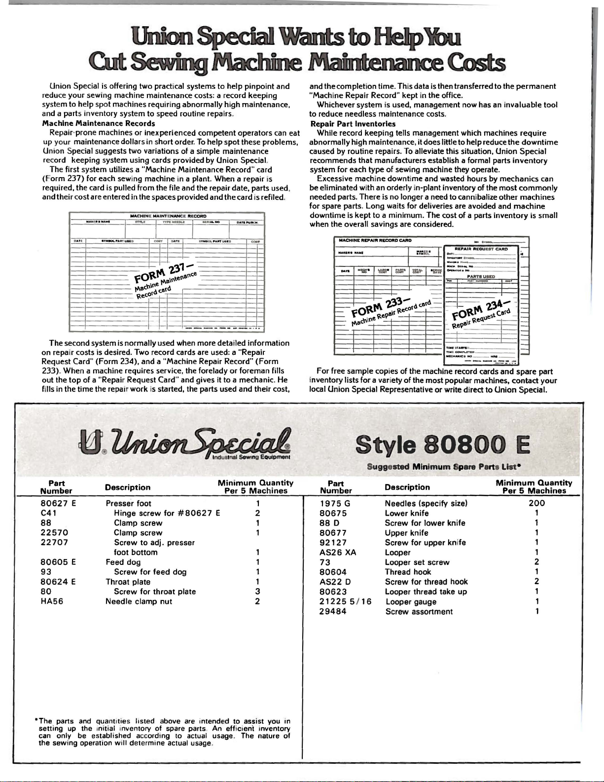
80627
C41
88
22570
22707
80605
93
80624
80
HA56
•The
setti
can
the sewi
parts
ng
only
E
E
E
and
qua
up
the tniti
be
established accordi
ng
operati
on
Description
Presser
Feed
Throat plate
Needle clamp
foot
Hinge
screw
for
Clamp
screw
screw
Screw
to
foot
bottom
dog
Screw
for
Screw
for
ntttle s hsted above
al
inventory of spare parts. An effictent inventory
will determi
#80627
adj. presser
feed
dog
throat
plate
nut
are
ng
to actual usage. The nature of
ne
actual usage.
Minimum
Per 5 Machines
E
intended to
1
2
1
1 Clamp
1
1
1
1
3
2
ass
ist you in
Quantity
Part
Number
1975
80675
88
D
80677
92127
AS26
73
80604
AS22
80623
21225
29484
Style
S
uggested Minim
Description
G
XA
D
5 /
Needles
Lower
Screw
Upper
Screw
Looper
Looper
Thread hook
Screw
Looper thread take
16
Looper gauge
Screw assortment
80800
um
Spare Parts Li
(speci
fy
size)
knife
for
lower
knife
for
set
for
knife
upper kni
screw
thread hook
fe
up
E
st
•
Minimum
Per 5 Machines
Quantity
200
1
1
1
1
1
2
1
2
1
Page 3
Catalog
No.
INSTRUCTIONS
FOR
137
M
ADJUSTING
80800
E
LIST
CLASS
Second
AND
OF
Styles
80800
OPERATING
PARTS
80800
F
Edition
80800
H
May~
1979
Copyright®
1973
By
Union
Rights
Special
Reserved
Corporation
in
All
Countries
UNION SPECIAL CORPORATION
INDUSTRIAl
Printed
SEWING
CHICAGO
in
U.S.A.
3
MACHINES
Page 4
IDENTIFICATION
OF
MACHINES
Each
ed
in
the
special.
tain
the
letter
suffixed
which
80800
herein.
this
described
table.
direction
"Z".
Styles
differs
".
This
Class.
with
UNION
name
Standard
letter
When
to
the
of
from
catalog
It
can
References
as
viewing
the
of
handwheel
SPECIAL
plate
"Z".
Standard
machines
also
pulley
on
Style
Example:
only
the
applies
be
the
numbers
minor
Style
similar
Style
specifically
applied
to
the
machine
to
the
is
away
machine
machine.
''Style
changes
number.
number.
APPLICATION
with
direction.
right
from
STYLES
is
identified
Style
have
in
one
80800
are
Example:
construction
in
to
discretion
such
as
it
sits
and
the
the
OF
numbers
or
more
E".
made
that
it
contains
OF
CATALOG
the
Standard
to
as
in
front
needle
operator.
MACHINES
by a Style
are
classified
letters
Special
in a standard
"Style
are
some
right.
bar
Style
80800
grouped
no
Styles
Special
left,
of
the
in
vertical
letters.
mechanic
number
suffixed.
numbers
machine.
EZ".
under
of
machines
Styles
front.
position.
which
as
a
Example:
back.
on
standard
but
never
contain
Class
of
machines
an
is
etc
Operating
stamp-
and
con-
the
a
"Z"
is
number
"Class
as
listed
in
.•
are
adjusting
Enclosed
Lubrication.
Eccentrics
Left
Edge
80 800 E
burlap,
foot.
Type
80800
burlap,
foot.
NOTE:
by
80 800 H
ply
Filter
Seam
speed
F
Type
Styles
removing
Sewing
or
Sewing
Sewing
Type
and
of
Equipped
1975 G needle.
Equipped
1975 G needle.
multi
cord
specification
2500
Flat
Lateral
Coil
Throat
head.
jute
head,
jute
80800 E and F machines
head,
wall
guided
R.
and
and
the
P.M.
Bed
Looper
Type
Plate
single
with
for
single
with
filter
for
paper
Bag
Closing
Travel.
Presser
7/8
Inch.
for
closing
or
mechanical
Maximum
closing
or
mechanical
Maximum
cord.
tape
bound
bags.
under
401-BSa-1.
presser
with
Springs.
filled
multiwall
chain
recommended
filled
multiwall
chain
recommended
closures
using
Union
Type
Machine.
Improved
Distance
medium
paper.
cutter.
medium
paper.
cutter.
can
foot.
1975 G needle.
One
and
Filter
and
Filter
also
on
filled
Special
Equipped
From
heaVY
Seam
speed
heaVY
Seam
speed
be
used
tape
Needle.
Bearings.
Center
weight
cord
cord
medium
with
guided
specification
2500
weight
guided
specification
2500
for
bound
automatic
Maximum
High
Smaller
Line
bags
R.
P.M.
bags
R.
P.M.
seaming
and
large
closing
Throw.
under
under
tape
recommended
Manual
Diameter
of
Needle
made
401-SSa-1.
made
101-SSa-1.
fabric
size
attachment.
from
presser
from
presser
bags
sfngle
cutter.
to
NOTE:
On
bly
are
21884
designed
Cis
Style
not
to
80800
included
available
use a strip
H.
the
with
as
ranging
tape
an
the
extra
reel,
machine.
folder.
send
from 2 1/8
4
Tape
and
filter
folder
charge
to 2 1/2
cord
item.
inches.
stand
and
and
adaptor
The
included
adaptor
assembly
assem-
folder
No.
is
Page 5
NEEDLES
Each
denotes
number,
in
thousandths
the
size
needles
Needle
by
this
Type
1975
To
sample
on
label. A complete
Selection
should
Success
use
of
a
reputation
more
UNION
the
stamped
number
packaged
catalog.
No.
G
have
needle,
pass
needles
than
kind
Type
Round
chromium
400/156,
freely
three-quarters
SPECIAL
of
on
of
an
represent
and
1975
The
needle
or
of
proper
in
the
packaged
for
producing
shank,
the
needle
inch,
sold
G,
description
shank,
plated-
480/188.
orders
the
type
order
needle
through
operation
under
needle
point,
midway
the
by
Size
square
promptly
and
would
needle
highest
of a century.
has
length,
shank,
between
complete
Union
100
is
and
point,
sizes
size
read:
size
eye
of
UNION
our
brand
quality
both a type
groove,
denotes
shank
symbol,
Special.
recommended
sizes
200/080,
and
number
is
available
Description
long
230/090, 250/100,
accurately
should
''100
needles,
determined
in
order
SPECIAL
name,
needles
and
size
number.
finish
largest
and
which
Antaeus,
by
to
produce a good
machines
~
in
and
diameter
eye.
Collectively,
is
for
the
are
listed
and
Sizes
double
filled,
be
forwarded.
Type
size
materials
other
of
given
machine
below:
300/120,
an
empty
1975
of
thread
can
be
•
which
and
The
type
details.
blade,
on
the
Styles
groove,
Use
G,
Size
used.
stitch
secured
workmanship
The
measured
the
label
350/140.
package,
description
250/100".
formation
is
backed
number
size
type
and
of
all
covered
spotted,
Thread
only
by
by
for
a
•
Clean
Oiling
applicable
diagram
Thread
machine
PL106
to
machine
machine
daily
Style
as
OILING
and
thoroughly
is
applicable
80800
illustrated
INSTRUCTIONS
oil
before
to
machine
H.
THREADING
in
Fig. 1 or
the
Styles
lA
morning
80800 E and
as
applicable.
and
afternoon
F,
start
PL179
•
is
5
Page 6
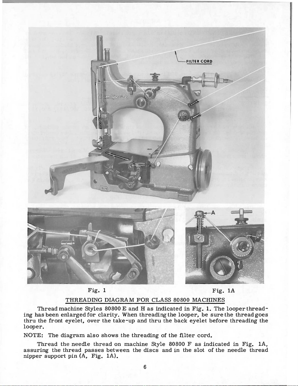
FILTER CORD
ing
thru
Thread
has
been
the
machine
front
Fig.
THREADING
Styles
enlarged
eyelet,
for
over
1
DIAGRAM
80800 E and
clarity.
the
When
take-up
FOR
Has
CLASS
indicated
threading
and
thru
the
the
80800
back
looper.
NOTE:
assuring
nipper
The
Thread
the
support
diagram
the
needle
thread
pin
(A,
also
thread
passes
Fig.
shows
on
between
lA).
the
threading
machine
the
Style
discs
6
of
the
80800 F as
and
in
MACHINES
in
Fig.
looper,
eyelet
filter
the
slot
Fig.
1.
be
sure
before
cord.
indicated
of
The
the
lA
looper
the
thread
threading
in
needle
thread-
Fig.
thread
goes
the
lA,
Page 7
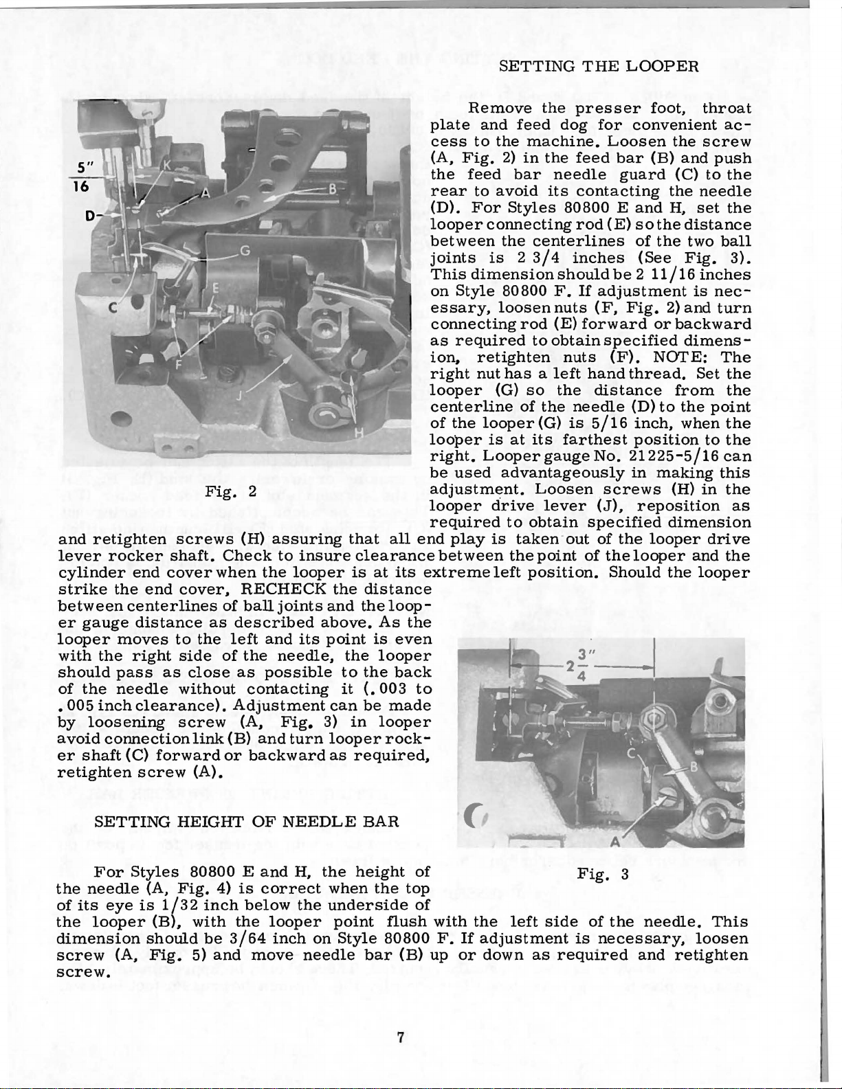
SETTING
THE
LOOPER
and
retighten
lever
rocker
cylinder
strike
the
between
er
gauge
looper
with
the
should
of
the
•
005
inch
by
loosening
avoid
er
connection
shaft
retighten
end
cover
end
center
distance
moves
right
pass
as
needle
clearance).
(C)
forward
screw
Fig.
screws
shaft.
cover,
lines
as
to
the
side
close
without
screw
link
(A).
2
(H)
assuring
Check
when
the
RECHECK
of
ball
described
left
and
of
the
as
possible
contacting
Adjustment
(A,
(B)
and
or
backward
to
insure
looper
joints
above.
its
needle,
Fig.
turn
that
clearance
is
the
and
point
the
to
it
can
3)
in
looper
as
required,
all
at
its
distance
the
loop-
As
the
is
even
looper
the
back
(.
003
be
made
looper
rock-
Remove
plate
cess
(A,
the
rear
(D).
and
to
Fig.
feed
to
For
looper
between
joints
This
dimension
on
Style
essary,
connecting
as
required
ion..
right
retighten
nut
looper
centerline
of
the
looper
right.
be
used
adjustment.
looper
required
end
play
between
extreme
to
the
feed
the
2)
bar
avoid
Styles
dog
machine.
in
the
needle
its
80800 E and
connecting
the
centerlines
is 2 3/4
should
80800
loosen
rod
to
F.
nuts
(E)
obtain
nuts
has a left
(G)
so
the
of
the
looper
is
Looper
at
(G)
its
gauge
farthest
advantageously
Loosen
cirive
is
left
lever
to
obtain
taken·out
the
point
position.
presser
for
Loosen
feed
bar
guard
contacting
rod
(E)
inches
be 2 11/16
If
adjustment
(F,
Fig.
forward
specified
(F).
hand
thread.
distance
needle
is
5/16
No.
21225-5/16
screws
(J),
specified
of
the
of
the
Should
foot,
throat
convenient
the
screw
(B)
and
(C)
the
needle
H,
set
so
the
distance
of
the
two
(See
Fig.
inches
is
2)
and
or
backward
dimens-
NOI'E:
Set
from
(D)
to
the
inch,
when
position
in
making
(H)
in
reposition
dimension
looper
looper
the
and
looper
ac-
push
to
the
the
ball
3).
nec-
turn
The
the
the
point
the
to
the
can
this
the
as
drive
the
SETTING
For
the
needle
of
its
eye
the
looper
dimension
screw
(A,
Styles
(A,
is
1/32
(B),
should
Fig.
HEIGHT
80800 E and
Fig.
4)
is
inch
below
with
5)
be
and
the
3/64
move
OF
NEEDLE
correct
looper
inch
H,
the
the
on
needle
BAR
height
when
the
underside
point
Style
flush
80800
bar
of
top
of
(B)
with
F.
up
the
If
adjustment
or
down
screw.
7
left
side
as
required
Fig.
is
3
of
the
necessary,
needle.
and
retighten
This
loosen
Page 8
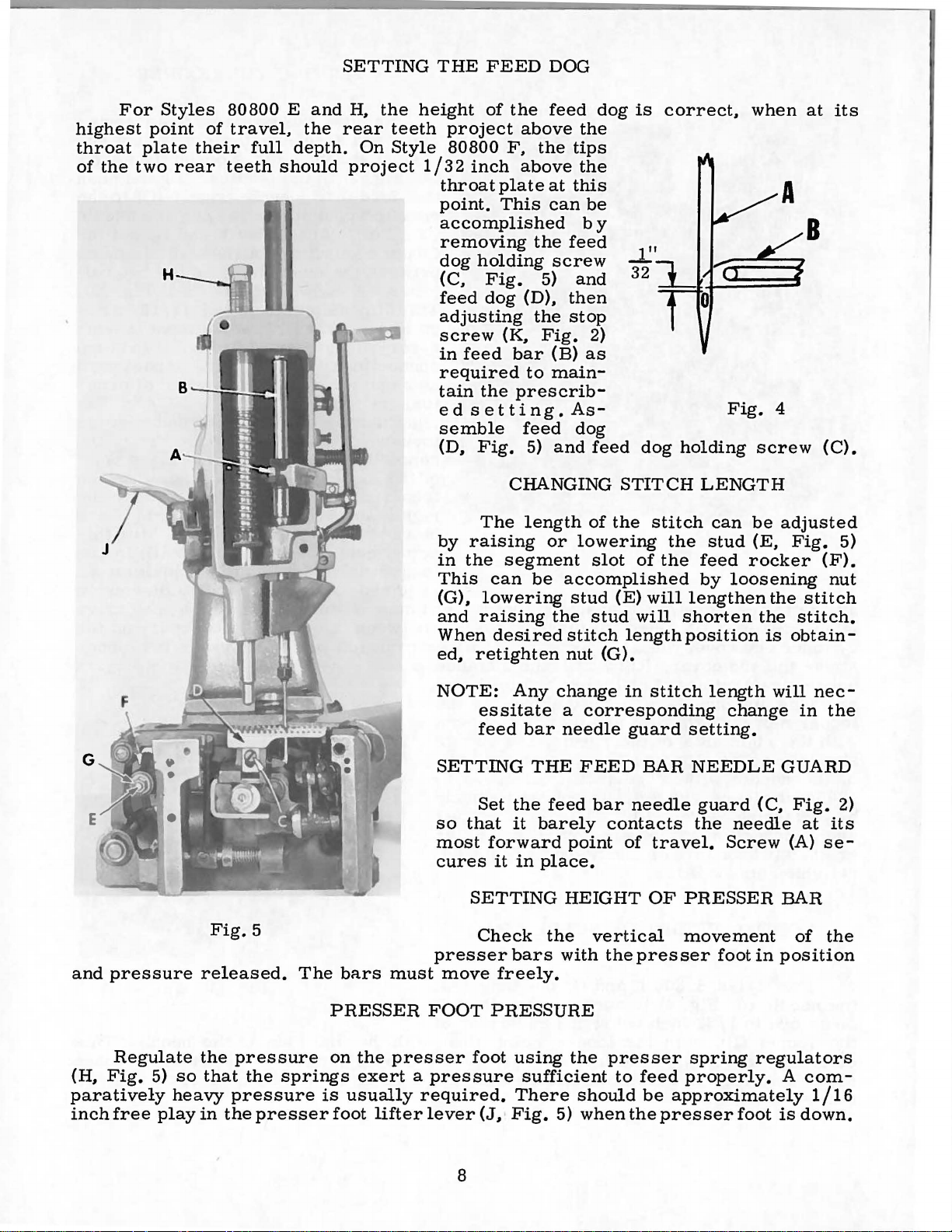
For
highest
throat
of
the
Styles
point
plate
two
H
their
rear
80800 E and
of
travel,
full
teeth
should
the
depth.
SETTING
H,
the
rear
teeth
On
Style
project
THE
height
1/32
throat
point.
accomplished
removing
dog
(C,
feed
adjusting
screw
in
required
tain
ed
semble
(D,
FEED
of
project
80800
inch
plate
This
holding
Fig.
dog
(K,
feed
the
setting.
Fig.
DOG
the
feed
above
F,
the
above
at
can
the
screw
5)
(D),
the
Fig.
bar
(B)
to
main-
prescrib-
feed
5)
and
the
tips
the
this
be
by
feed
and
then
stop
2)
as
As-
dog
feed
dog
is
dog
correct,
holding
when
Fig.
4
screw
at
B
its
(C).
G
and
pressure
Fig.
5
released.
The
bars
must
The
by
raising
in
the
segment
This
(G),
and
When
ed,
NOTE:
SETTING
so
most
cures
presser
move
can
lowering
raising
desired
retighten
essitate
feed
Set
that
forward
it
SETTING
Check
freely.
CHANGING
length
be
Any
bar
THE
the
it
barely
in
place.
bars
of
or
lowering
slot
accomplished
stud
the
stud
stitch
nut
(G).
change
a
corresponding
needle
FEED
feed
bar
point
HEIGHT
the
vertical
with
STITCH
the
stitch
of
the
(E)
will
will
length
in
stitch
guard
BAR
needle
contacts
of
travel.
OF
the
presser
LENGTH
can
the
stud
feed
by
loosening
lengthen
shorten
position
length
change
setting.
NEEDLE
guard
the
Screw
PRESSER
movement
foot
be
(E,
rocker
the
the
is
will
(C,
needle
in
adjusted
Fig.
obtain-
GUARD
Fig.
(A)
BAR
position
(F).
nut
stitch
stitch.
nec-
in
the
at
its
se-
of
the
5)
2)
Regulate
(H,
Fig.
paratively
inch
free
5)
heavy
play
so
the
that
in
the
pressure
the
springs
pressure
presser
PRESSER
on
the
exert a pressure
is
usually
foot
lifter
FOOT
presser
required.
lever
PRESSURE
foot
using
There
(J,
·
Fig.
8
sufficient
5)
the
presser
should
when
to
spring
feed
properly.
be
approximately
the
presser
regulators
A
foot
is
com-
1/16
down.
Page 9
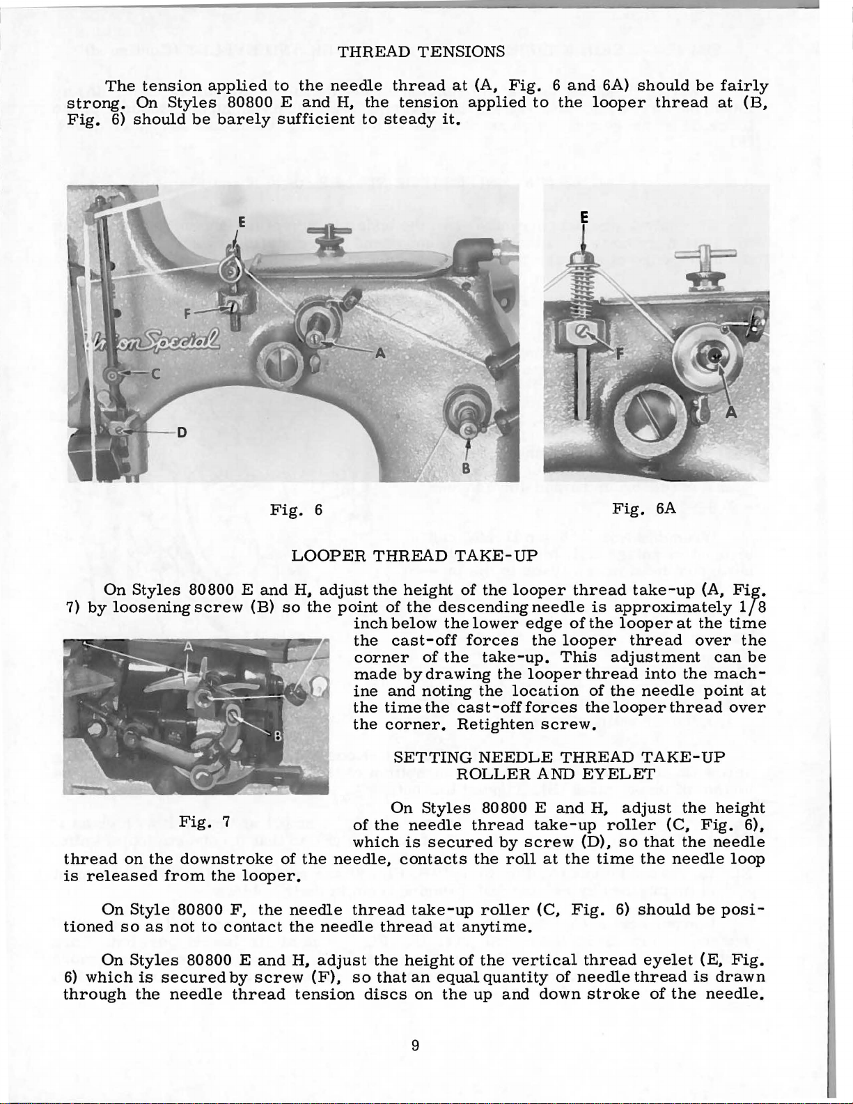
The
strong.
Fig.
6)
tension
On
Styles
should
applied
80800 E and
be
barely
to
the
needle
sufficient
THREAD
thread
H,
the
tension
to
steady
TENSIONS
at
(A,
applied
it.
Fig. 6 and
to
the
6A)
looper
should
thread
be
fairly
at
(B,
7)
by
thread
is
released
On
tioned
On
Styles
loosening
on
the
Style
so
as
80800 E
screw
Fig.
7
downstroke
from
the
80800
not
to
contact
and
(B)
looper.
F,
the
Fig.
LOOPER
H,
so
the
of
the
needle
the
6
adjust
point
of
which
needle,
thread
needle
THREAD
the
of
inch
below
the
cast-off
corner
made
ine
and
the
time
the
corner.
SETTING
On
the
thread
height
the
descending
the
of
the
by
drawing
noting
the
Styles
needle
is
secured
contacts
take-up
at
TAKE-UP
of
the
looper
lower
forces
take-up.
the
the
location
cast
-off
Retighten
NEEDLE
ROLLER
80800 E
thread
by
screw
the
roll
roller
anytime.
needle
edge
the
looper
This
looper
forces
screw.
THREAD
AND
and
take-up
at
the
(C.
Fig.
thread
is
approximately
of
the
adjustment
thread
of
the
the
looper
EYELET
H,
roller
(D),
time
Fig.
6)
6A
take-up
looper
thread
into
needle
TAKE-UP
adjust
(C,
so
that
the
should
(A,
at
the
over
the
point
thread
the
Fig.
the
needle
be
Fi~.
lf
time
the
can
be
mach-
at
over
height
6),
needle
loop
posi-
8
On
6)
which
through
Styles
is
the
80800 E
secured
needle
and
by
screw
thread
H,
adjust
(F),
tension
so
discs
the
that
height
an
equal
on
the
9
of
the
quantity
up
and
vertical
of
down
thread
needle
stroke
eyelet
thread
of
the
(E,
is
drawn
needle.
Fig.
Page 10
SETTING
On
loosening
increase
(F).
Style
screw
or
NEEDLE
80800
(F)
decrease
THREAD
F,
adjust
and
tension
the
raising
as
TAKE-UP
tension
or
lowering
required
ROLLER
on
needle
to
suit
needle
sewing
AND
thread
thread
conditions.
EYELET
nipper
nipper
(Continued)
(E,
Fig.
support
Retighten
6A)
by
pin
screw
to
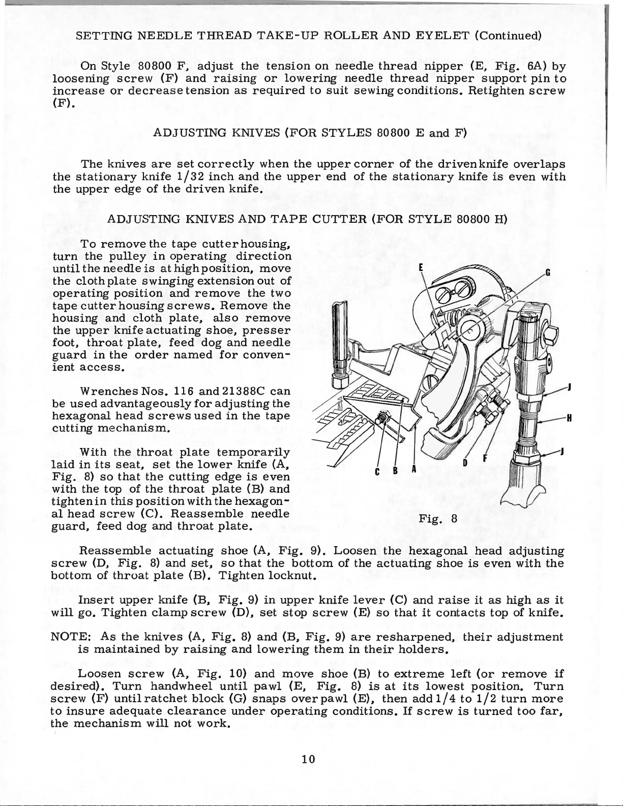
The
the
stationary
the
upper
To
turn
until
the
the
the
cloth
operating
tape
cutter
housing
the
upper
foot,
guard
ient
throat
in
access.
Wrenches
be
used
hexagonal
cutting
mechanism.
ADJUSTING
knives
are
knife
edge
of
the
ADJUSTING
remove
pulley
needle
plate
position
and
knife
the
the
in
is
swinging
housing
cloth
actuating
plate,
order
Nos.
tape
operating
at
high
and
screws.
plate,
feed
named
116
advantageously
head
screws
set
correctly
1/32
inch
driven
KNIVES
cutter
position,
extension
remove
shoe,
dog
and
for
used
KNIVES
and
knife.
AND
housing.
direction
the
Remove
also
remove
presser
and
needle
for
conven-
21388C
adjusting
in
the
when
the
TAPE
move
out
two
the
can
the
tape
(FOR
the
upper
of
STYLES
upper
end
corner
of
CUTTER
80800 E and
of
the
the
stationary
(FOR
STYLE
F)
driven
knife
80800
knife
is
H)
overlaps
even
with
With
laid
in
Fig.
with
8)
the
tighten
al
head
guard,
Reassemble
screw
bottom
Insert
will
go.
NOTE:
is
Loosen
desired).
screw
to
insure
the
mechanism
the
throat
its
seat,
so
that
top
of
in
this
position
screw
feed
(D,
of
(C).
dog
Fig.
throat
upper
Tighten
As
the
maintained
screw
Turn
(F)
until
adequate
plate
set
the
the
cutting
the
throat
with
Reassemble
and
throat
actuating
8)
and
plate
knife
clamp
knives
by
(A.
raising
(A,
handwheel
ratchet
clearance
will
not
temporarily
lower
edge
plate
the
set.
(B).
(B.
screw
Fig.
Fig.
block
work.
knife
is
(B)
hexagon-
needle
plate.
shoe
so
(A,
that
Tighten
Fig.
9)
(D).
8)
and
10)
until
(G)
snaps
under
(A.
even
and
Fig.
the
bottom
locknut.
in
upper
set
stop
and
(B.
lowering
and
move
pawl
(E.
over
operating
9).
knife
screw
Fig.
them
shoe
Fig.
pawl
Loosen
of
the
the
actuating
lever
(E)
so
9)
are
resharpened.
in
their
(B)
to
8)
is
at
(E).
then
conditions.
Fig.
hexagonal
(C)
and
that
holders.
extreme
its
add
If
screw
shoe
raise
it
contacts
lowest
1/4
8
is
their
left
position.
to
is
head
even
it
as
top
adjustment
(or
remove
1/2
turn
turned
adjusting
with
the
high
as
of
knife.
Turn
more
too
far.
it
if
10
Page 11

ADJUSTING
If
ratchet
ing
rod
distance
require
facture.
(H,
Fig.
of
the
slightly
KNIVES
block
and
8)
connecting
different
by
AND
pawl
means
rod
settings
TAPE
will
of
should
CUTTER
not
engage,
the
due
to
(FOR
it
locknuts
be 4 1/16
slight
STYLE
may
(J).
inch.
be
necessary
The
Individual
accumulation
80800
correct
of
H)
(Continued)
to
adjust
center
tape
clippers
tolerances
connect-
to
center
may
in
manu-
The
length
at
the
Fig.
finish
9
is
not
adjustable.
Move
(or
reassemble
that
pawl
extreme
have
of
side
polished
pawl
to
may
operation
When
is
raised
10)
should
shoe
tape
(B,
within 1 1/2
handwheel.
engage
there
the
9).
for
should
pilot
The
uating
length
shoe
of
material
shoe
(C)
right
end
overlap
insure
of
machine.
actuating
slightly,
allow
Fig.
Make
their
be
end
of
position
(A,
tape
at
the
(B,
if
it
will
rest
end
of
to
trigger
pawl
10)
and
turns
sure
full
len&th.
about
the
knives
of
the
Fig.
extending
start
Fig.
was
on
shoe.
the
right
slightly
action
shoe
trip
(C)
knife
or
that
3116"
tape
9)
of
10)
to
removed)
top
Shoe
and
over
(A.
Fig.
dog
(D,
to
slide
should
less
the
When
opening
(See
Figure
cutter
controls
beyond
the
closure.
right
so
of
the
should
point
out-
during
9)
Fig.
off
clip
of
the
knives
open
at
act-
the
the
The
Fig.
to
start
(F
toward
chine
the
10)
vary
of
and
G)
the
to
opposite
distance.
spring
weights
(H)
of
Attach
housing.
The
cord
ate
stand
unit
installation
wood
paper
ling
core
the
tape
tape.
trip
dog
can
be
retarded
the
length
the
closure.
and
turn
handwheel
shorten
the
direction
The
actuating
is
adjustable
material.
cloth
folder,
are
under
is
plate
tape
furnished
No.
is
shown
provided
and a tension
operating
or
of
the
Loosen
the
operating
end
distance
to
lengthen
shoe
for
and
reel
as a separ-
21884
on
for
for
cam
advanced
tape
screws
of
the
and
tension
various
tape
cutter
a:nd
C.
Their
PL162.
the
roll
control-
(E,
at
the
cam
ma-
the
filter
in
A
of
11
Fig.
10
Page 12

ADJUSTING
A
width
It
is
adjusted
have
accomplished
folder
to
and
The
(a)
(b)
(c)
(d)
(e)
be
folder
The
of
The
yet
There
livery
delivery
plate.
The
The
KNIVES
of
tape
to
suit
readjusted,
by
loosening
moving
is
upper
the
conveyor
front
the
tape
is
end
end
line
of
tape
AND
ranging
the
if
the
folder
set
correctly
surface
and
rear
passes
approximately
of
folder
and
stitches
guide
TAPE
from
widest
the
the
sections
of
belt.
sections
freely
the
is
collars
CUTTER
2 1 I 8
width
tape
two
when
the
1164
and a space
presser
approximately
are
when
used
hexagonal
and
the
middle
are
and
the
inch
foot
set
(FOR
to
2 1 I 2
it
leaves
is
less
head
resetting
following
section
set
so
two
edges
space
of
approximately
when
5116
to
lead
STYLE
inches
the
than 2 112
bolts
the
tape
conditions
is
level
that
they
are
between
the
latter
inch
the
tape
80800
can
be
factory,
inches
nearest
guide
prevail:
and
parallel
guide
even.
the
1132
is
bearing
from
the
centrally
H)
(Continued)
used
the
throat
in
consequently
wide.
the
left
collars.
with
tape
plate
inch
on
edge
into
the
folder.
This
end
of
the
side
accurately,
and
between
the
throat
of
the
tape.
the
folder.
will
is
the
de-
the
12
Page 13

ILLUSTRATIONS
This
catalog
of
various
actual
listing
required
sections
position
of
the
in
the
parts
has
been
of
the
in
the
machine.
with
particular
ORDERING
arranged
mechanism
On
their
view
part
being
REPAIR
to
simplify
are
the
page
number,
shown.
shown
opposite
PARTS
ordering
so
that
the
the
description,
repair
parts
illustration
and
parts.
may
the
Exploded
be
seen
will
number
be
of
views
in
the
ir
found a
pieces
Numbers
position
ordering
dicated
Example:
23
24
of
parts.
Component
by
29442 p
80636 c
25
26
27
28
29
30
31
32
33
replacement
should
this
part
80649
80642
22894 L
22894 c
80645
80636 A
22515 A
It
will
be
At
the
book.
number
in
that
indenting
88 F
A
660-90
be
noted
of
this
ordered.
back
This
will
is
known.
the
first
part
in
Always
parts
their
Looper
in
the
part
of
the
facilitate
column
the
illustration.
use
the
of
sub-assemblies
descriptions
Drive
Looper
Screw,
Oil
Felt
Felt
Oil
Looper
Spot
Set
Looper
Ball
Fork,
Screw,
above
example
individually
book
will
locating
are
reference
Reference
part
number
which
under
Eccentric
Lever
Holder,
Wick
Drive
Screw
Drive
for
be
IDENTIFYING
Connection
for
looper
for
---------------------------------------Eccentric-------------------------------
Screw
found a numerical
--------------------------------------
---------------------------------------
Ball
for
looper
ball
fork----------------------------------
that
is
not
recommended,
the
illustration
numbers
listed
the
Assembly
Stud
the
in
can
description
lever
looper
-------------------------------
drive
bearing
PARTS
only,
numbers
the
second
be
furnished
of
-------------------------
----------------------------connection-----------------
lever
connection-------------
ball
stud
is
not
so
index
and
description
and
merely
should
the
-------------------
listed.
complele
of
column.
for
main
all
the
never
repairs
sub-assembly.
The
parts
indicate
be
used
are
in-
reason
sub-assembly
when
is
shown
only
that
the
in
1
1
4
1
1
1
1
1
1
1
1
in
the
Where
some
identification
appear.
OF
SPECIAL
subsidiaries
proved
and
parts
Emblem.
workmanship.
forwarded
directed.
of
the
Part
numbers
IMPORTANT!
MACHINE
Success
Needles
scientific
durability
Genuine
are
stamped
Each
Prices
A
the
smaller
letter
in
and
are
needles
are
f.
o.
charge
FOR
the
net
b.
construction
parts,
is
represent
ON
WHICH
USE
operation
and
authorized
principles,
assured.
are
with a reproduction
trademark
cash
shipping
is
made
permits,
and
stamped
ALL
ORDERS,
PART
GENUINE
of
Repair
distributors.
and
packaged
is
and
are
point.
to
on
in
the
these
Parts
are
your
subject
cover
same
IS
each
those
to
distinguish
part,
PLEASE
ORDERED.
NEEDLES
machines
as
furnished
They
made
with
labels
of
guarantee
TERMS
to
Parcel
Post
postage
part
where
regardless
AND
with
the
change
and
is
stamped
the
construction
the
part
INCLUDE
REPAIR
can
be
secured
by
the
are
designed
utmost
marked
familiar
of
the
highest
without
shipments
insurance.
with its
from
similar
of
the
PART
PARTS
only
Union
precision.
~
Union
Special
according to
Special
quality
notice.
are
insured
part
does not
ones.
catalo
g in
NAME
with genuine
Corporation,
Maximum
•
Genuine
trademark,
in
All
shipments
unless
numbe
permit,
which
AND
the
rna
terials
r . On
an
they
STYLE
UNION
its
most
ap-
efficiency
repair
U S
and
are
otherwise
13
Page 14

A B C
'
..
~YJ~
A 1
~
13
12
14
Page 15

MAIN
FRAME,
BUSHINGS,
OILING
PARTS
AND
BASE
PLATE
Ref.
No.
1
2
3
4
5
6
7
8
9
10
11
12
13
':'14
':'15
,;'16
':'17
':'18
19
20
21
22
23
24
25
26
27
28
29
30
31
32
33
34
35
36
37
38
Part
No.
80673
80689
80689
80690
41046
80644
88
80898
666-79
22
894
99256
664
HA81
HA95
11667
652-24
22639
11667
22638
21388
80640
80639
80639
80692
22539
80698
79048
69
50-430
80694
80692
22539
22814
22894
89
80646
80647
80662
80673
660-457
E
A
A
A
G
J
F-16
v
B
K
B
AH
E
F
E
D
A
H
D
E
B
J
B
D
Blk.
Description
Needle
Oil
Oi.l
Oil
Spring
Plug
Set
Oiler,
Sight
Set
Screw,
Taper
Spot
Set
Adapter
Washer,
Screw,
Adapter
Screw,
Wrench,
Bar
Cup,
Cup,
Cup,
Bushing,
small,
small,
large-------------------
Valve
Oiler------------------------------
for
for
upper-------
Styles
Style
80800 E and F ---------
80800 H only------------
Screw-------------------------------------
Screw,
Feed
Screw,
Screw,
Screw,
for
needle
Oiler
for
Dowel
Base,
for
for
Plate,
for
1/4
for
plug
for
needle
arm
------------------
Pin
for
crankshaft
for
crankshaft
for
Styles
adapter
for
adapter
inch
screw
lever
Assembly
-----------------------
connection
--------------------
lever
oiler----------------
------------------------------bearing
bearing
Styles
80800 E and F ----------80800 E and
base,
Styles
plate,
open
for
Styles
80800 E and F ----------
for
Styles
end,
for
and F ----------------------------------------
Transverse
Looper
Looper
Knife
Plug
Shaft
Screw------------------------------------Thread
Screw,
and F ---------------------
Washer,
Dowel
Main
Feed
Plug
Pin.
Shaft
Rocker
Screw-------------------------------------
Screw,
Set
Screw.
Spot
Screw,
Needle
Needle
Presser
Needle
Dust
Cover
Shaft
Shaft
Shaft
Bushing,
Lubricator,
for
thread
for
Styles
for
Bushing.
for
arm---------------------------------
for
for
Lever
Lever
Bar
Bar
Bushing,
(not
Bushing-----------------------Bushing,
Bushing,
right---------
left-----------------------
for
Styles
for
Styles
lubricator,
80800 E and F ----------------
Style
Shaft
Shaft
Shaft
Bushing,
80800 H only
left
Bushing
needle
needle
Bushing,
Bushing,
lower
shown
and
----------------------
lever
lever
lower---------------------
----------------------
on
picture
80800 E and F ------
for
-
middle---------------
oiler---------------shaft
front----------------
rear
-
--------------
-
--------------
bearing
-
-------------
--------
housing--------
housing---------
F
----------------
80800 E and
80800 E and
Styles
80800
-
------------
E
80800 E and F -----
Styles
80800
E
------------------
----------------
bushings--------
----------------
plate)
-----------
1
9
6
2
2
2
2
1
- - 1
1
1
2
1
1
1
3
F - 3
1
F - 4
1
2
1
1
2
1
1
2
2
2
2
2
1
2
1
2
1
1
2
1
1
'
~
Available
as
an
extra
send
and
charge
item.
15
Page 16

2
16
16
Page 17

MAIN
FRAME.
CLOTH
PLATES,
HOUSINGS
AND
MISCELLANEOUS
COVERS
Ref.
No.
1
2
3
4
5
6
7
8
9
10
lOA
11
12
13
13A
14
15
16
17
18
19
20
21
22
22A
Part
No.
80887
376
64
y
35733
80888
99256
22814 B
80897
29479
29479 X
22574
80284
80684
80438
80440
81239
8564
92121
12957
80683 H
80683
93 A
664
94
89
B
y
F-16
H
E
Description
Face
Screw,
Screw,
Lock
Top
Screw,
Screw.
Tape
Screw.
Cloth
Cloth
Screw.
Taper
Looper
Looper
Screw.
Spring,
Cloth
Cloth
Screw.
Hinge
Screw.
Spring
End
End
Plate-----------------------------------------
for
face
plate
for
top
cover--------------------------------
Nut,
Cover-----------------------------------------
Cutter
orily----------------------------------------------
Cover,
Cover,
for
for
for
for
Plate
Plate
for
Dowel
Thread
Thread
for
for
Plate
Plate
for
Pin.
for
for
Washer,
screw
arm------------------------------------arm-------------------------------------
Housing.
tape
cloth
looper
hinge
end
cutter
Assembly,
Assembly,
plate
Pin------------------------------------
Guard,
Guard.
cloth
Bolt
Extension
for
for
plate
Knob
pin
swing-out
cover
for
Style
Styles
-------------------------------
No.
64
Y------------------------
for
Style
housing.
for
for
assembly----------------------
for
for
thread
end
guard
extension
------------------------------Bolt---------------------------
-------------------------------cover-----------------------
------------------------------cover------------------------
80800
80800 E and F -----------------
80800
Style
Styles
Style
Styles
H orily
for
80800 H only----------
80800 E and
80800
80800 E and
---------------------bolt------------------
--------------------
H
---------------
Style
H orily
80800 H
F--------
----------
F--------
Amt.
Req.
1
2
1
1
1
1
2
1
2
1
1
3
2
1
1
2
1
1
1
2
1
1
1
1
1
17
Page 18

18
Page 19

ROLLING
THREAD
GUIDES,
THREAD
EYELETS
AND
THREAD
TENSION
PARTS
Ref.
No.
1
2
3
4
5
6
7
8
9
10
11
12
13
*13A
14
15
16
17
18
19
20
21
22
23
24
25
26
27
28
29
30
31
32
33
34
35
36
37
38
39
40
41
42
43
44
45
46
47
48
49
50
51
Part
No.
88
80665
80665
80665
88
80668
HS53 B
12964
81086
HA1286
22560
22894
G-111
80250
80250
80250
22743
88
80668
HS52 B
81086
12964
HA1286
22560
22894
AS137
28
HA103
AS137
22560
80665
51292
80665
81256
81256
AS137
28
22560
108
107
110-4
110-3
110-2
HA1349
80676
HA1348
80667
HS106
22894
AS137
HA103
28
AS137
c
A
B
c
G
B
AD
B
A
c
c
B
AD
A
c
B
B
'E
F-4
F
A
c
B
A
AD
A
B
c
Description
Screw,
Filter
Rolling
Screw,
Thread
Rolling
and
Screw,
Thread
Screw,
Needle
only---------------------------------------------------Needle
Needle
only
Thread
Screw,
Tension
Tension
Tension
F
Tension
Tension
and F --------------------------------------------------
Tension
Tension
Tension
Tension
Tension
Screw,
Thread
for
filter
Cord
Thread
Thread
Screw,
Thread
Needle
H
Rolling
Rolling
Screw,
Screw,
Thread
Needle
Screw,
Thread
Thread
Thread
Thread
Screw------------------------------------------------
and
Thread
Screw,
Thread
Thread
Spring
Rolling
Spring
Screw,
for
rolling
Guide,
Thread
--------------------------------------------------
Thread
Rolling
Spring
Spring
Screw
for
rolling
Eyelet
for
thread
Thread
Thread
Thread
--------------------------------------------------Eyelet
for
thread
Regulating
Spring
Spring,
H
-----------------------------------------------
Spring,
Spring,
Post
Disc
Post
Disc
Post---------------------------------------------
for
thread
Eyelet
Eyelet
for
Eyelet
cord
guide--------------------------------
Guide-----------------------------------------
Guide
Roller
for
thread
Guide
Ball
-------------------------------------------
for
Guide
Thread
Thread
for
rolling
for
thread
Guide
Ball---------------------------------------
-------------------------------------------
-------------------------------------------
and
for
thread
Eyelet
Eyelet
Nipper
Tension
Nipper
Assembly
Sleeve
Eyelet
Ferrule------------------------------------
Ferrule
--------------------------------------------Ferrule
Stop
and
thread
Assembly
Support
guide
Roller
Rolling
Thread
for
spring
thread
Styles
Guide
Guide
Roller
Rolling
Thread
thread
Support
---------------------------------------Support---------------------------------
eyelet
---------------------------------------Support---------------------------------
eyelet
Nut
for
needle
for
looper
for
looper
Pin
eyelet
Support
---------------------------------------
Support
---------------------------------Thread
-------------------------------------Guide
guide
80800 E and
Assembly,
Wire
Holder
thread
guide
---------------------------------Thread
Guide
guide
Assembly------------------------
eyelet
and
Support
Spring,
Support
---------------------------------
assembly----------------------:_
-----------------------------------thread
thread
thread
-------------------------------------
-------------------------------------
------------------------------------and
Assembly
eyelet
--------------------------------
---------------------------
-------------------------------
roller
--------------------------------
guide
roller
------------------------------
support
support
------------------------------
-------------------------
Guide
Axle
Axle
Pin,
Disc,
------------------------
assembly
H
for
Styles
----------------------------
-------------------------wire
-------------------------
Guide
-------------------------
assembly--------------------
assembly---------------
for
Style
for
Style
for
on
Styles
on
Style
on
Styles
assembly
-----------------------
Axle
Axle
80800 F only
Style
---------------
-------------------
-------------------80800 E and
--------------------
---------------
80800
80800
80800 H -----------
80800
F
80800
F
E,
E
--------------
--------
Amt.
Req.
'1
1
1
1
___ 2
2
2
1
1
1
2
4
2
2
2
1
1
1
1
1
1
1
1
1
1
1
1
1
1
1
1
1
1
1
1
1
1
1
1
1
1
1
1
1
1
1
1
1
1
1
1
2
2
Replaced
*
by
Ref.
No
13
on
late
model
machines.
19
Page 20

4
~
29
20
Page 21

NEEDLE,
NEEDLE
AND
BAR,
NEEDLE
LOOPER
LEVER,
THREAD
LOOPER,
CAST-OFF
LOOPER
PARTS
DRIVE
Ref.
No.
Page
80673 c
80617
HA
1975
806
BP108
51134 v
HA54A
80615
80643
22811
29066
29793 A
22738 B
80649 c
22768 B
80642 c
22894 c
22894 L
51236 A
W0-2
80642 B
22811 B
W0-3
AS26 XA
80608 A
15465 F
12987 A
15745 B
80657 A
22729 c
6040 A
HA61 D
41331 G
80641 B
HS-36
35841 c
22729 c
80623
80637
22517
12538
80653 A
80653 I
80604
HA102 A
80653
80653 H
23
1
2
3
4
5
6
7 22564 D
8
9
10
11
12
13 22565 c
14
15 22894 K
16 22894
17
18
*19
20
21
22
23
24
25
26 80842
27
28
29
30
31
32
33
34
35 22894 c
36 1280
37 80639
38
39
39A
40
40A 29479
41 80613 A
42
43
44
45
46
47
48
49
50
51 269
52
53
54
55
56
57
58
59
60
61
62
63
64
65
66
66A
67
63 AS22
69
70
70A
71 22743
~'
See
Part
No.
56
G
334
59 A
91
666-260
AD
u
666-149
482
c
18
73
88
237 A
666-149
18
666-149
K
36 E
J79
J
D
for
component
Description
Needle
Needle
Needle
Needle
Needle
Needle
Screw,
Needle
Needle
Screw,
Needle
Spot
Set
Needle
Screw,
Needle
Looper
Link
Looper
Wool
Collar,
Nut,
Looper
Nut,
Looper,
Looper,
Screw,
Looper
Looper
Oil
Nut,
Screw,
Connecting
Nut,
Oil
Looper
Looper
Screw,
Looper
Nut,
Looper
Looper
parts.
Bar
Guard-------------------------------------------------------------
Bar
-------------------------------------------------------------------
Clamp
Nut-------------------------------------------------------------
----------------------------------------------------------------------Thread
Bar
Screw,
Screw,
for
Lever
Felt
Bar
for
Lever
Screw,
Screw
L~ver
for
Lever
Avoid
Oil
Screw,
Oil
Screw,
Strap,
Looper
Pin,
Wool
Avoid
Screw--------------------------------------------------------------------
Yarn--------------------------------------------------------------------
for
Screw,
for
Rocker
for
for
Rocker
Looper
Differential
Check
Looper
Rocker
Screw,
Shell---------------------------------------------------------------------
Ball
Wick,
for
for
for
Wick,
Rocker
Steel
BallStud-----------------------------------------------------------------
Shell--------------------------------------------------------------------Screw,
Thread
for
Drive
Screw,
for
Thread
Thread
ThreadHook--------------------------------------------------------------
Screw,
ThreadEyelet-------------------------------------------------------------
Holder,
Holder,
Screw,
Eyelet----------------------------------------------------------
Connection---------------------------------------------------------
for
needle
for
link
Link
Oil
Wick
Link---------------------------------------------------------------
link
-----------------------------------------------------------------
for
for
needle
Shaft
needle
Connecting
Eccentric
Wick------------------------------------------------------------------
for
Wick
looper
oil
Holder-----------------------------------------------------------
for
link
for
looper
Avoid
SetScrew-------------~-----------------------------------------------
Spot
Screw------------------------------------------------------------
for
looper
Yarn, 2 strands------------------------------------------------------
Connecting
looper
for
collar----------------------------------------------------------
looper
rocker
Shaft-----------------------------------------------------------
looper
rocker
for
Styles
for
Style
looper
Assembly-------------------------------------------------------
Rocker------------------------------------------------------------
Screw----------------------------------------------------------------
NUt----------------------------------------------------------------
Rocker
Ball
for
shell-----------------------------------------------------------
Stud
-----------------------------------------------------------------
for
No.
connecting
looper
Rod----------------------------------------------------------------
connecting
for
No. 80641
Ball
Washer,
for
shell-----------------------------------------------------------
Take-up--------------------------------------------------------
looper
Lever-----------------------------------------------------------
for
looper
rocker
Cast-off
Cast-off
for
thread
for
for
for
thread
thread
needle
bar
pin
------------------------------------------------------------
Pin---------------------------------------------------------
-------------------------------------------------------------
pin
------------------------------------------------------------
needle
lever-----------------------------------------------------
------------------------------------------------------------
lever
wick
pin
avoid
Eccentric----------------------------------------------------
avoid
rocker
assembly------------------------------------------------
80800 E and
80800 F only,
-------------------------------------------------------------
Rocker
Cone
Joint
80657
rod,
thread
rod,
Joint
for
ball
thread
drive
ball
hook-----------------------------------------------------
No.
80653 A -----------
No.
80653 I ---------------------------------------------------
eyelet
eyelet---------------------------------------------
connection--------------------------------------------
lever----------------------------------------------------
connecting
Rod
Assembly
holder--------------------------------------------------
-------------------------------------------------------eccentric--------------------------------------------
eccentric
Link--------------------------------------------------
shaft
ball
joint
Cone---------------------------------------------------
Stud,
Assembly,
A------------------------------------------------------
right
cast-off
left
B------------------------------------------------------
Assembly,
stud-------------------------------------------------
take-up------------------------------------------------
lever-----------------------------------------------
joint
Assembly,
Assembly,
rod
Bearing
-------------------------------------------------
H, 401
marked'~"---------------------------------------
hand
hand
assembly
---------------------------------------------------
bearing-----------------------------------
Assembly----------------------------------
----------------------------------------------
assembly------------------------------------
assembly
101
assembly
thread
for
for
---------------------------------------
stitch-------------------------------------
stitch
--------------------------------------
left
----------------------------------------
thread
---------------------------------------
--------------------------------------
----------------------------------------
right
---------------------------------------
---------------------------------------
Styles
80800 E
Style
80800 H only
-
---------------------------------------
and F -----------------------
-------------------------
Amt.
~
1
1
1
1
1
1
1
1
1
1
1
1
1
1
2
1
1
1
1
1
2
1
1
1
2
1
1
1
2
1
1
1
1
1
1
1
1
1
1
1
1
2
1
1
1
2
1
1
1
1
2
2
1
1
2
1
1
1
1
1
1
1
1
1
2
1
1
1
1
1
1
1
1
1
1
21
Page 22

22
Page 23

TAPE
CUTTER
DRIVE,
LOOPER
AND
PULLEY
DRIVE,
RIM
CRANKSHAFT
ASSEMBLY
Ref.
No.
1
2
3
4
5
6
7
8
9
10
11
12
13
14
15
16
17
18
19
20
21
22
23
24
25
26
27
28
29
30
31
32
33
34
35
36
37
38
39
39A
40
41
42
43
44
45
46
47
48
49
50
51
52
53
54
55
55A
56
57
Part
No.
29139 E
G21710
22586 A
1230 B
1230 D
80630
22587
15430 c
80230
15430
15430
29132
80630
22587
21703 L
22894
22894 L
80638
136
96
80691
80640
29442 p
80636 c
88 F
80649 A
660-90
80642
22894
22894
80645
80636
22515 A
29781 A
29781 B
29066 u
80650 B
22587
80656 A
80630 c
W0-3
80630
80630
80636 B
80652
22587
80622 B
80622 A
HA66 K
80681
22891
22539
80685 E
HA95
HA81
80621 A
80821 H
80821 B
80
80674
E
L
D
AG
F
c
A
L
c
A
D
A
Description
Tape
Cutter
Ball
Screw,
Spring,
Spring
Tape
Nut,
left
only
Connecting
Felt,
Nut,
Tape
Looper
Nut,
Looper
Looper
Crankshaft
Crankshaft
Woodruff
Crankshaft
Plug
Crankshaft
Set
Spot
PulleyHub
Pulley
Pulley
Screw,
Lock
--------------------------------------------------------
for
right
only
--------------------------------------------------------
Cutter
Tape
Tape
Clamp
Spot
for
Looper
Oil
Felt
Looper
Looper
Ball
Screw,
Needle
Nut,
Wool
Felt
Needle
Nut,
tube
Guide
Crankshaft
Crankshaft,
Crankshaft,
Set
Screw,
Screw,
Screw,
and
F-------------------------------------------------------
Washer,
Bearing
Stud
-------------------------------------------------
for
for
Pin------------------------------------------------
Cutter
Screw,
hand
thread,
Rod
connecting
hand
Driving
Cutter
Screw,
Cutter
Set
Screw
Spot
Screw--------------------------------------------
Drive
Drive
Drive
Screw
Rim, 6 inch
Rim, 4 1/4
for
Lever
Screw
Screw------------------------------------------------
looper
Lever
Eccentric
Lever
Screw,
Felt
Holder,
Oil
Wick
Drive
Spot
Screw
Set
Screw
Drive
Fork,
for
Eccentric
Eccentric
Lever
Needle
Screw,
Needle
left
hand
Yarn------------------------------------------------
Oil
Wick,
Lever
right
hand
---------------------------------------------------Fork,
Screw,
Key,
for
Collar
------------------------------------------------
for
Bearing
for
crankshaft
for
---------------------------------------------------
lock
for
Assembly,
spring
pin·-------------------------------------------
for
Tube,
thread,
for
drive
for
for
ball
Lever
Lever
Bearing,
for.bearing
for
for
crankshaft
crankshaft
washer
pin--------------------------------------
Drive
Driving
Driving
for
Bearing
bearing------------------------------------
for
connecting
for
Style
rod
tube,
for
Eccentric
Eccentric
bearing
Eccentric------------------------------
-------------------------------------------Shaft
Rocker
--------------------------------------------eccentric
Rocker
Assembly
Connection
looper
for
looper
--------------------------------------------Eccentric------------------------------------
-------------------------------------------
--------------------------------------------
Ball
Stud-------------------------------------
looper
fork
Connection
thread,
3/16
Connecting
thread,
Styles
Style
pulley
---------------------------------------------
Housing,
working
inch
pulley
drive
---------------------------------------
Assembly,
Assembly,
Connection
for
bearing--------------------------------
Ball
inch
crankshaft
for
80800 H only
hub
bearing
working
and
hub------------------------------------
upper,
---------------------------------
80800 H
for
Style
connecting
Assembly,
------------------------------------
-------------------------------
ball
Shaft
-------------------------------
----------------------------------
lever
connection----------------------
lever
ball
for
for
Upper
Bearing
Stud
for
bearing
--------------------------------
needle
diameter, 7 1/4
Rod
Oil
for
needle
bearing--------------------------
crankshaft
------------------------------------
80800 E and F ------------------------
-----------------------------------
bearing
includes
housing
diameter,
diameter,
pulley
rim
for
Style
80800 H only------
rod
tube,
for
Style
80800 H
only---------------------
80800 H only--------------
rod
tube,
for
Style
for
Style
80800 H only
Bearing
stud-------------------------
------------------------------
stud
Styles
Style
Bearing
lever
Tube
housing
housing-----------------------
----------------------
connection------------------
-----------------------80800 E and F ---------
80800 H
-----------------------
connecting
----------------------
lever
eccentric
--------------------------
sponge
bushing--------------------
-----------------------
for
Style
for
--------------------------
only
Assembly------------
inches
connecting
assembly--------
80800 H
Styles
-----------
rod
long----------
rod
hole
-----------
only
80800
80800 H
oil
tube--
oil
------
E
---
Amt.
Req,
1
1
1
1
1
1
2
1
1
1
1
1
1
2
1
1
1
1
2
1
1
1
1
1
4
1
1
1
1
1
1
1
1
1
1
1
1
2
1
1
1
1
1
1
1
1
2
1
1
1
1
2
1
1
1
1
1
1
1
4
1
23
Page 24

-------1
I
I
20
v
I
I
I
I
4
---
I
24
Page 25

KNIFE
DRIVE
FOR
FEED
STYLES
LIFT
80800 E
AND
FEED
and
F,
DRIVING
FEED
PARTS
DOGS,
FEED
BARS,
Ref.
No.
1
2
3
4
5
6
7
8
9
10
11
12
13
14
15
16
17
18
19
20
21
22
23
24
25
26
27
28
29
30
31
32
33
34
35
36
37
38
39
40
41
42
43
44
45
46
47
48
49
49A
50
51
52
53
54
55
56
57
58
Part
No.
80634 c
80699 B
89
HA95
97 X
80605 E
80626 E
80625
80677
88 D
80675
80671
92127
98
459
460
88
HS110
18
80670
29132
10349
80672
22894 L
80650 c
97 A
75A
660-90
80649 B
93
22596
22874
69 H
80625 H
80605 H
73
93A
80634 H
89
W0-3
80411
22706
80634 E
22894 c
80633 H
80408 A
W0-3
80696
80696
80654 H
80654
29099
80606 c
22894 L
80651 c
80606 D
22894 D
HA18A
HA20A
80634
482
T26
89
A
c
H
X
EB
AF
c
c
Description
Feed
Bar,
for
Styles
Feed
Bar
Set
Screw,
Set
Screw,
Screw,
Feed
Feed
Needle
Upper
Screw,
Lower
Knife
Chain
Shaft
Tension
Nut,
F
Ball
Chain
Screw,
Screw,
Screw,
Washer,
Needle
Feed
Set
Screw,
Feed
Wool
Feed
Feed
Feed
Stop
Feed~ker---------------------------------------------------------
Feed
Wool
Stitch
Stitch
Feed
Feed
Feed
Feed
Stitch
Stitch
Felt,
fo~
Dog,
Dog,
Guard,
Knife,
for
Knife,
Bar,
Screw,
Screw
Cutter
Collar,
Screw,
Spring,
for
-----------------------------------------------------------------
Stud
Cutter
Ball
Knife
Chain
Felt
Oil
Felt
for
for
for
Guard,
Dog,
Screw,
for
Bar,
Set
Screw,
Yarn,
Bar
SetScrew-------------------------------------------------------
Lift
Bar
Set
Screw,
Screw,
Set
Screw,
Rocker
Yarn,
Regulating
Regulating
Rocker
Rocker
Drive
Feed
Spot
Feed
Lift
Spot
Regulating
Regulating
for
Needle
for
needle
feed
for
Style
for
Style
for
for
lower
for
for
Styles
for
for
knife
Knife
for
for
chain
cutter
Washer,
Drive
Stud----------------------------------------~---------------
Driving
SpotScrew--------------------------------------------------
Cutter
Screw,
Screw,
Oiling
Holder
feed
feed
feed
foi""
feed
marked
for
Style
for
feed
feed
for
Style
for
for
feed
Shaft------------------------------------------------------Eccentric
Shaft
Collar
for
for
for
Shaft---------------------------------------------------
for
feed
Eccentric
Eccentric
Eccentric
Drive
Screw,
Rocker
Eccentric--------------------------------------------------
Screw,
feed
lift
80800 E
for
upper
Pad--------------------------------------------------
stitch
Eccentric---------------------------------------------
Guard
feed
guard,
dog
support,
80800 E only
80800 F
Styles
Styles
knife,
Styles
80800 E
knife,
bar
Lever
knife
shaft
for
for
for
dog,
dog,
dog,
driving
Stud,
Stud,
Eccentric
for
Stud
Stud
eccentric
bar,
collar
knife
drive
for
ball
Connection
Eccentric
Drive
dog
Connection------------------------------------drive
drive
-------------------------------------------------for
for
for
screw
'rtrL'~
80800 H only
dog
support,
eccentric
80800 H
feed
bar
Fork
------------------------------------------------
feed
regulating
feed
rocker
for
for
Connection
Connection
Assembly
for
feed
Nut--------------------------------------------Washer
and
F------------------------------------
Stop
bar-------------------------------------------
80800 E and F --------------------------------
80800 E
for
80800 E
---------------------------------------------Shaft,
bar,
connection
stud,
connection----------------------------------connection-----------------------------------
Style
Style
Style
bar-------------------------------------------
shaft
---------------------------------------------
bar
rocker----------------------------------------
Styles
Style
feed
Connection---------------------------------
lift
fork---------------------------------------
Pin----------------------------------- 1
for
Styles
for
Styles
--------------------------------------
only
--------------------------------------
and F ---------------------------------
Styles
and F ---------------------------------
and
for
Styles
for
for
Styles
------------------------------------------for
for
Assembly,
------------------------------------------
80800 E only----------------------------80800 F only----------------------------80800 H only-----------------------------
-----------------------------------------for
Style
--------------------------------------
for
fork,·•···-----------------------------
only
--------------------------------------
----------------------------------as
shaft
collar--------------------------------
stud
shaft
-------------------------------as
80800 E and F -------------------------
80800
---------------------------------------
drive
eccentric
-----------------------------------------
80800 E
80800 E
80800 E and
F------------------------------------
80800 E
Styles
80800 E
Styles
Bushing,
Bushing,
eccentric
80800 E
assembly,
Styles
for
80800 H
Style
80800 H
----------------------------------
H--------------------------------
---------------------------------
and F ------------------and F -------------------
F------------------------
and F --------------------
80800 E
80800 E
for
for
---------------------------
and
and
for
Styles
only
Style
Styles
F-----------------
F--------------------
and
F------------------
Styles
and F ----------------
80800 E and
---------------------
only
------------------
80800 H ------------
80800 E and
80800 E
F--------
and
F------
Amt.
required
required
Req.
1
2
1
1
1
1
1
2
1
2
1
1
1
1
1
1
1
1
1
1
1
1
1
1
2
2
1
1
1
1
1
1
1
1
1
1
1
2
1
1
1
2
2
2
1
2
1
1
1
1
1
1
1
1
1
1
1
1
1
1
25
Page 26

26
Page 27

THROAT
AND
PLATES,
PRESSER
PRESSER
FOOT
FEET,
LIFTER
PRESSER
PARTS
BAR
Ref.
No.
1
2
3
4
5
6
7
8
9
10
11
12
13
14
15
16
17
18
19
20
21
22
23
24
25
26
27
28
29
30
31
32
33
34
35
36
37
38
39
40
41
Part
No.
22580 A
39536
80689 B
HA63 F
80666
22894 c
22894 c
80648 A
80632
80649
80661 B
80661 B
80861 A
22894 c
80627
80627 K
12934
22560 A
22560
99251
80627 L
80628
80627 E
80627
80627
22570
22707
12934
22560 B
80628 E
80624
482
258
258 A
420
482
88 A
531
80
88
907
C41
CA
c
c
c
c
M
A
B
H
EB
EA
A
E
Description
Screw,
Pressure
Presser
Presser
Presser
Presser
Presser
Spring,
Stud,
Presser
andF------------------------------------------Presser
Presser
Collar,
Presser
Screw,
Throat
Presser
Throat
Throat
for
Spring
Bar
Bar
Set
Screw,
Bar
Set
Screw.
Foot
Nut,
Check
Foot
Set
Clar.np
Presser
Set
Lock
s.et
Set
Hinge
Presser
Presser
Presser
Clamp
Clamp
Screw.
Lock
Lock
Set
Hinge
for
Lifter
for
for
lifter
Bar.
Bar,
Bar,
for
Screw,
Foot,
S~rew,
Screw.
Screw.
for
Plate,
Foot,
Screw.
Plate,
Plate,
No.
39536
Plug.
Nut
Nut,
Screw.
throat
Screw---------------------------------Screw------------------------
Nut,
Nut,
Screw
for
Regulator
Spring-------------------------------Lifter
for
Stop
for
Lifter
foot
-----------------------------------Lever
lifter
lever-------------------------------
front
front,
rear.
presser
for
for
Screw----------------------------------
Foot
to
for
for
to
Foot
for
for
Foot
Foot
for
adjustment
for
for
to
----------------------------------
for
for
CA---------------------------
presser
Collar--------------------------
presser
Collar
presser
Lever
lifter
Screw
lever-----------------------------
and
for
for
bar----------------------------
presser
Style
Shank---------------------------align
alignment
adjustment
align
for
presser
Bottom
plate----------------------------Style
Bottom
Shank----------------------------
align
Style
Style
80800 H only-----------------
Styles
adjustment
alignment
80800 F only----------------80800 E only-----------------
spring
--------------------------
bar
lifter
--------------------------bar
stop
-------------------------
lever
rear.
Style
Style
80800 H only----------------
presser
presser
presser
screw
Stud-------------------
for
80800 H only----------80800 H only-----------
bar
collar---------------
foot-----------------
screws-----------------
of
presser
foot-----------------
foot
--------------------------
80800 E and F --------------
--------------------------
of
presser
screw-----------------
screws-----------------
foot-----------------
regulator---------
collar----------
collar-----------
stud-------------
Styles
------------------
80800
foot
foot
.
----------
bottom-----
E
bottom
Amt.
Req.
2
2
2
2
1
2
1
2
1
1
1
1
1
1
2
1
1
1
2
1
2
1
1
3
- 1
1
1
1
3
1
1
1
1
1
1
1
1
2
2
1
1
1
27
Page 28

Page 29

No.
29486 D AUTOMATIC
FOR
STYLE
TAPE
80800 H ONLY
CUTTER
ASSEMBLY
Ref.
No.
10
11
12
13
14
15
16
17
18
19
20
21
22
23
24
25
*26
27
28
29
30
31
32
33
34
35
36
37
38
39
40
41
42
43
44
45
46
47
48
49
50
51
52
53
*54
*55
56
57
58
59
60
61
62
1
2
3
4
5
6
7
8
9
Part
No.
80237
22517
80277
80272
80271
22528
80287
80288
22768
906
907
80266
51134
666-260
80285
77
80285
80238
57 WD
25
94
93
80286
76099 G
80276
80270
88
80274
80278
907
80288
80288
22599
22559
22564
80288
80288
22760 A
80288
22557
80269
93 A
906
907
80268
HSllO
99246
94
80288
907
906
80281 A
80279
80297
97
80283
22806
6042
73
80275
8372
99248
A
v
cc
A
K
G
J
c
B
D
A
F
A
D
G
A
c
A
Spring,
Screw,
Upper
Upper
Upper
Screw,
Upper
Upper
Screw,
Stop
Lock
Washer,
Taper
Adjusting
Set
Adjusting
Spring,
Screw,
Screw,
Screw,
Screw,
Upper
Dowel
Upper
Upper
Set
Tape
Upper
Lock
Upper
Spring,
Screw,
Screw,
Screw,
Trip
Trip
Screw,
Trip
Screw,
Stop
Screw,
Stop
Lock
Stop
Tension
Stop
Screw,
Trip
Lock
Stop
Upper
Shaft,
Actuating
Screw,
Actuating
Screw,
Washer,
Set
Lower
Washer,
Screw,
Knife----------------------------------------------------------Knife
Knife
Knife
Knife
Screw,
Nut,
Link
Felt
Screw,
Knife
Pin,
Knife
Knife
Screw,
Cutter
Knife
Nut,
Knife
Lever
Lever
Lever
Screw
Screw
Nut,
Pin,
Screw,
Dog
Nut,
Screw,
Knife
for
Screw,
Knife
Description
for
upper
for
upper
for
upper
for
upper
for
for
Pin,
Oil
Screw
for
Screw
for
upper
for
upper
for
upper
for
upper
for
upper
for
for
for
for
upper
for
upper
for
upper
for
trip
Shoe
-----------------------------------------------------------
for
trip
Spring·----------------------------------------------------
for
trip
Block------------------------------------------------------
for
stop
-----------------------------------------------------------
for
for
Spring,
for
trip
Cam
for
for
Actuating
upper
Shoe,
for
actuating
Ratchet
for
tape
for
for
for
for
lower
knife
lever-------------------------------------------
knife
clamp-------------------------------------------
Clamp
Lever
Operating
Actuating
for
screw
Wick-----------------------------------------------------
Operating
Operating
Operating
Support
Operating
Actuating
upper
for
tape
----------------------------------------------------------
lower
----------------------------------------------------
----------------------------------------------------
knife
lever
Ratchet
Pawl
knife
actuating
upper
upper
taper
upper
tape
upper
lever
lever
lever--------------------------------------------------
screw
stop
for
upper
dog
--------------------------------------------------------
stop
upper
knife
for
cutter
lower
knife
knife
on
upper
for
ratchet
Stop,
for
link
Stop,
for
knife
operating
knife
operating
knife
lever
knife
lever
knife
operating
Pawl--------------------------------------------
knife
Lever------------------------------------------Lever
cutter
--------------------------------------------------Lever
knife
Pawl
knife
actuating
knife
actuating
knife
actuating
shoe
-----------------------------------------------------spring--------------------------------------------
block--------------------------------------------
screw
knife
upper
knife
cam
screw-----------------------------------------------
knife
Lever--------------------------------------------
actuating
upper
shoe
Block
support------------------------------------------
cutter
knife
knife
knife-------------------------------------------------
------------------------------------------Block------------------------------------
-------------------------------------------pawl------------------------------------
operating
operating
knife
block---------------------------------------
upper
pin
-------------------------------------------
upper
-------------------------------------------
-------------------------------------------
operating
Buffer
support
Shaft--------------------------------------
actuating
Trip
---------------------------------------------
----------------------------------------------
actuating
knife
actuating
actuating
-----------------------------------------------
actuating
lever------------------------------------
knife
-----------------------------------------
----------------------------------------------
Adjusting
support-----------------------------------------
screw·---------------------------------------
-----------------------------------------------
ratchet
ratchet
operating
knife
lever------------------------------
knife
lever
ratchet
ratchet
pawl
-----------------------------------
pawl--------------------------------
Washer
--------------------------------------
lever
Dog-----------------------------------pawl
trip
pawl
trip
pawl
trip
lever
lever
lever
Screw
block
block
ratchet
------------------------------
block---------------------------
block
-----------------------------
spring
dog----------------------------
dog
spring
dog----------------------------
spring
lever---------------------------
spring
------------------------------
Stop-----------------------------
-----------------------
stop
screw
block------------------
spring
---------------------
stop
screw----------------
---------------------
--------------------------
------------------------
--------------
Amt.
Req.
1
1
1
1
1
1
1
1
2
1
1
1
1
1
1
1
1
1
2
1
1
2
1
1
1
1
2
1
1
1
1
1
2
1
1
1
1
1
1
1
1
2
1
1
1
1
1
2
1
1
1
1
1
1
1
1
2
2
1
1
1
1
*
Not
component
parts
of
No.
29486 D tape
clipping
assembly.
29
Page 30

NUMERICAL
INDEX
OF
PARTS
Part
No.
W0-2
W0-3
:HA18 A
:HA20A
AS22 D ••••••••
AS26
HS36 K ••••••••
HS52 B ••••••••
HS53 B ••••••••
IIA.54 A
:HA56
IIA.61 D
:HA63 F
IIA.66 K
:HA81
:HA95
HA102A
HA103 B ••••••••
HS106
BP1
HS110 ~ ••••••••
Glll
..........
..••......
18
..........
........
••••••••
25
cc
.......
T26
.........•
XA
•••••••
28
c
........
36 E ........
C41
...........
50-430
••••••••
.•........
57 WD
84 y
69 H
7 3
73
7 5 A
77
J79
80
88
88 A
88 D
88 F ........
89
91
93
93 A .••...••
94
96
97
97 A ...••••.
97 X ..•...••
98
107
108
08
110-2
110-3
110-4
•••••••
••••••••
••••••••
........
••••••••
.......•
••••••••••
c
........
.....•..
..........
J
•••••••.•
••••••••••
.......••.
.... ~ .....
......•.
........
...•......
.....•..•.
..•.•..•..
...•..•.••
....••.••.
...•...•••
..........
...•.....•
••••••••
••••••••••
...•..•...
....•••..•
••••••••••
.........
........
••••••••
..........
Blk
•••
•
Page
No.
21
21,
23,
21,25
25
25
21
29
25
21
19
21
21
27
15
19
19
21
21
29
21
27
17
23
15,
25
21
25,29
25
29
21
23,
27
15,
23
15,
19,
25,
27.
27
25
23
15,
17,25
21
25,29
17,25,29
17,29
15,23,25
23
29
25
25
25
21
19
19
19
19
21
19
19
19
25,29
19
25
21,
29
Part
No.
136
..........
AS137
AS137 A ••••••••
IIA.1286 B
IIA.1348
HA1349
1975 G ••••••••
8372 A ••••••••
8564
10349
11667 K ••••••••
11667
12538
12934 A ••••••••
12957 E ••••••••
12964
12987 A ••••••••
15430
15430 D ••••••••
15430 L ••••••••
15465 F ••••••••
15745 B ••••••••
21388
21703 L ••••••••
G21710
22515 A ••••••••
22
22528
22539
22557
. . . . . . . . . .
237 A ........
258
. . . . . . . . . .
258 A ........
269
..........
334
. .........
376
..........
420
..........
459
. .........
460
. . . . . . . . . .
482
c
........
531
. . . . . . . . . .
652-24
660-90
660-457
664
666-79
666-149
666-260
906
906 A ••..•..•
907
1230 B ••••••••
1230 D ••••••••
1280
•••••••
•••••••
••••••
F-16
.......
••••••
••••••
.....•....
. .........
..........
••••••••
. .........
. . . . . . . . . .
6040 A ••••••••
6042 A ••••••••
. .........
..........
v
........
••••••••••
c
........
c
........
AH
•••••••
••••••••••
517
••••••••••
..........
..........
. .........
•••••
30
Page
No.
23
19
19
21
27
27
21
21
17
27
25
25
21,
25,
27
15
23, 25
15
15,
17
15
21
21, 29
29
29
27,29
23
23
21
19
19
19
21
21
29
29
17
25
15
15
21
27
17
19
21
23
23
23
21
21
15
23
23
23
21,29
29
15,23
29
27
Part
No.
22559
22560
22560 A •••••••••
22560 B •••••••••
22564
22564 D •••••••••
22565
22570
22574
22580 A •••••••••
22586A
22587
22596
22599
22638 B •••••••••
22639 B •••••••••
22706 A •••••••••
22707
22729
22738 B •••••••••
22743
227
22768
22768 B •••••••••
22806 G •••••.•••
22811
22811 B •••••••••
22814B
22874
22891
22894
22894 D •••••••••
22894
22894 K •••••••••
22894 L •••••••••
22'894
29066
29099 X •••••••••
29132
29132AG
29139 E •••••••••
29442
29479
29479 X ••••....••
29479
29781 A •..•.••••
29781 B ••..•••.•
29793 A ••...•••.
357 33 B
35841
39536
41046 G •••••••••
41331 G •••••••••
51134
51236 A •••••••••
51292
J
•..•..•..
. .........
..........
c
.........
. .........
..........
•••••••••
..........
. .........
..........
..........
c
.........
..........
60 A
•••••••••
. .........
..........
••.••••••
c
.........
. .........
c
.........
J
•.•.•...•
AD
u
.........
AF
••••••••
•.••••••
p
.•....•••
. .........
y
.........
••••.••••
c
.........
CA
••••••••
v
.........
F-4
•••••••
.
......
Page
No.
29
19
27
19,27
29
21
21
27
17
27
23
23
25
29
15
15
25
27
21
21
19,
21
29
29
21
29
21
21
15,17
25
23
21,
23,
27
25
15
21
21,
23,
19,
21
21,23
25
25
23
23
23
21
17
17
23
23
21
17
21
27
15
21
21,29
21
19
25,
25
Page 31

NUMERICAL
INDEX
OF
PARTS
Part
No.
76099
79048
80230
80237
80238
80250
80250 A •••••••••
80250 B •••••••••
80266
802
80269
80270
80271
80272
80274
80275
80276
80277
80278
80279
80281 A •••••••••
80283
80284
80285
80286A
80287
80288 A •••••••••
80288 B •••••••••
80288
80288
80288
80288
80288
80297
80408 A •••••••••
80411
804
80440
80604
80605 E ••••••••
80605
80606
80606
80608 A •••••••••
80613 A •••••••••
80615
80617
80621 A •••••••••
80622 A •••••••••
80622 B •••••••••
80623
80624 E •••••••••
80625
80625
80626 E •••••••••
G
•••••••••
•••••••••••
•••••••••••
•••••••••••
•••••••••••
•••••••••••
•••••••••••
68
•••••••••••
•••••••••••
•••••••••••
•••••••••••
•••••••••••
•••••••••••
•••••••••••
•••••••••••
•••••••••••
•••••••••••
•••••••••••
•••••••••••
H
.........
•••••••••••
•••••••••
•••••••••••
c
.........
D
.........
F
.........
G
.........
K
•••••••••
D
.........
•••••••••••
38
•••••••••••
•••••••••••
•••••••••••
H
c
........
D
........
•••••••••••
•••••••••••
•••••••••••
•••••••••••
H
.........
••••••••
Page
29
15
23
29
29
19
19
19
29
29
29
29
29
29
29
29
29
29
29
29
29
29
17
29
29
29
29
29
29
29
29
29
29
29
25
25
17
17
21
25
25
25
25
21
21
21
21
23
23
23
21
27
25
25
25
No.
Part
No.
80627 E •••••••••
80627 K •••••••••
80627
80627
80627
80627
80628 E •••••••••
80628
80630
80630
80630
80630 E •••••••••
80630
80632
80633
80634
80634 E •••••••••
80634
80634
80636 A •••••••••
80636 B •••••••••
80636
80637
80638 A •••••••••
80639
80639 E •••••••••
80639
80640
80640 E •••••••••
80641 B •••••••••
80642
80642 B •••••••••
80642
80643
80644
80645
80646
80647
80648 A •••••••••
80649
80649 A •••••••••
80649 B •••••••••
80649
80650 B •••••••••
80650
80651
80652 A •••••••••
80653
80653 A •••••••••
80653
80653
80654
80654
80656 A •••••••••
80657 A •••••••••
L
.••••••••
M
•••••••••
EA
••••••••
EB
••••••••
H
•••••••••
•••••••••••
c
.........
D
•••••••••
F
•••••••••
c
.........
H
•••••••••
c
.........
H
•••••••••
EB
••••• • ••
c
.........
•••••••••••
•••••••••••
F
•••••••••
•••••••••••
•••••••••••
c
.........
•••••••••••
•••••••••••
•••••••••••
•••••••••••
•••••••••••
•••••••••••
c
.........
. c
.........
c
.........
•••••••••••
H
•••••••••
I
.....•...
•••••••••••
H
•••••••••
Page
27
27
27
27
27
27
27
27
23
23
23
23
23
27
25
25
25
25
25
23
23
23
21
23
21
15
15
23
15
21
23
21
21
21
15
23
15
15
27
27
23
25
21
23
25
25
23
21
21
21
21
25
25
23
21
No.
Part
No.
80659 A ••••••••••
80661 B ••••••••••
80662 B ••••••••••
80665 A ••••••••••
80665 B ••••••••••
80665
80665 E ••••••••••
80665
80666
80667
80668
80670
80671
80672
8067
80673
8067
80674
80675············25
80676 A ••••••••••
80677
80681
8
8068
80684
80685 E ••••••••••
80689 A ••••••••••
80689 B ••••••••••
80690 A ••••••••••
80691············23
80692
80692 E ••••••••••
80694
80696
8069
80698 A ••••••••••
80699 B ••••••••••
80821 B ••••••••••
80821 H
80842
80861 A ••••••••••
80887
80888
80897
80898
81086
81086
81239
81256
81256 A ••••••••••
92121
92127
99246
99248
99251
99256
c
..........
F
••••••••••
c
..........
••••••••••••
••••••••••••
••••••••••••
••••••••••••
••••••••••••
3 c
..........
D
••••••••••
3 E
••••••••••
••••••••••••
••••••••••••
••••••••••••
0
68 3 ••••••••••••
3 H
••••••••••
••••••••••••
D
••••••••••
D
••••••••••
••••••••••••
6 H
••••••••••
..........
••••••••••••
••••••••••••
••••••••••••
••••••••••••
••••••••••••
c
..
.;
.......
G
••••••••••
••••••••••••
••••••••••••
••••••••••••
••••••••••••
••••••••••••
••••••••••••
••••••••••••
••••••••••••
Page
No.
21
27
15
19
19
19
19
19
27
19
19
25
25
25
21
15
15
23
19
25
23
17
17
17
23
15
27
15
15
15
15
25
25
15
25
23
23
21
27
17
17
17
15
19
19
17
19
19
17
25
29
29
27
15,17
31
Page 32

WORLD'S
FINES
T
QU
ALITY
*
INDUSTRIAL
SEWING
MACHINES
UNION
SPECIAL
maintains sales
facilities throughout the world. These offices
aid
you
in
the selection of the right sewing
equipment for your
Special representatives
tory trained
promptly
tion, there
serve you.
ATLANTA,
BOSTON,
CHICAGO,
DALLAS,
LOS ANGELES,
NEW
YORK, N. Y.
PHILADELPHIA,
and
is
Check with
GA.
MASS.
ILL.
TEXAS
CAL.
PA.
and
a Union Special Representative to
particular operation. Union
and
service men
are
able
to serve your needs
efficiently. Whatever your loca-
him
today.
MONTREAL, CANADA
TORONTO, CANADA
BRUSSELS, BELGIUM
LEICESTER,
LONDON,
PARIS, FRANCE
STUnGART,
and
service
are
ENGLAND
ENGLAND
GERMANY
will
fac-
Representatives
industrial
UNION SPECIAL
400
N.
FRANKLIN
and
cities
dlstrlbutart
throughout
ST.,
In
all
Important
the
world.
CORPORATION
CHICAGO,
ILL.
60610
 Loading...