

Page 1
STY
LES
63900N
63900P
I N
DUSTRIAL
SEWING
MACHINES
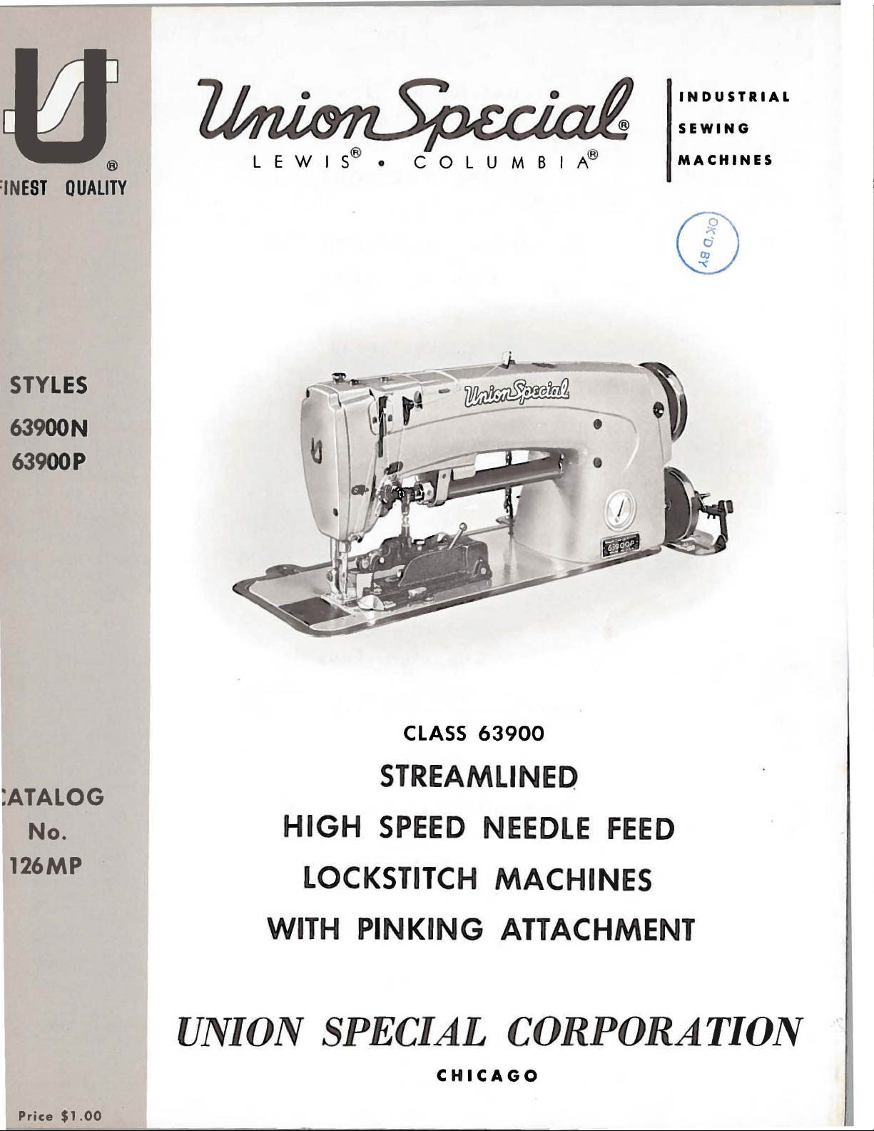
CLASS
63900
STREAMLINED
ATALOG
No.
126MP
HIGH
LOCKSTITCH
WITH
UNION SPECIAL
Price
$1.00
SPEED
PINKING
C H
ICAGO
NEEDLE
MACHINES
ATTACHMENT
CORPORATION
FEED
Page 2
Catalog
No.
126
MP
(Supplement
ADJUSTING
Streamlined
to
Catalog
INSTRUCTIONS
FOR
AND
LIST
OF
CLASS
Styles
63900
N
No.
OPERATING
PARTS
63900
Lockstitch
63900
126M)
p
First
Copyright
Edition
1964
by
Union
Rights
Special
Reserved
Corporation
in
All
Countries
UNION SPECIAL CORPORATION
INDUSTRIAL
SEWING
CHICAGO
MACHINES
Printed
in
U.S.
A.
2
October,
1977
Page 3
IDENTIFICATION
OF
MACHINES
Each
into
the
special.
the
letter
"Z".
When
the
standard
Styles
which
This
junction
not
on
certain
Opposite
number,
use
the
Adjusting
with
Styles
UNION
name
Standard
"Z".
only
of
differs
catalog
therewith.
Style
63900 A parts
description,
part
63900
SPECIAL
plate
Example:
minor
Style
machines
from
is a supplement
63900 A are
the
number
and
on
the
Style
numbers
changes
number.
similar
the
Style
Only
illustrated
are
illustration
and
listed
operating
Nand
P.
machine
machine.
"Style
Example:
number,
APPLICATION
those
shown
page,
amount
in
the
instructions
is
have
63900
are
made
in
construction
in
to
Catalog
parts
and
in
phantom
required.
second
identified
Style
one
or
N''.
Special
in a standard
"Style
that
it
OF
which
listed
parts
column.
included
by a Style
numbers
more
63900
are
letters
are
contains
CATALOG
No.
126 M
are
used
at
the
to
help
identified
When
are
classified
suffixed,
Style
NZ".
represent
numbers
machine,
grouped
no
letters.
and
on
back
locate
ordering
number
under a Class
should
Styles
of
this
the
by
which
as
standard
but
never
contain
a
"Z"
is
Example:
be
used
63900 N and P and
book.
63900 N and P parts.
detail
repair
only
For
number,
parts
areas
is
stamped
contain
the
letter
suffixed
number
"63900''.
in
con-
clarity,
part
always
concerned
and
to
The
herein.
in
this
class.
given
of
High
Light,
Horizontal
Needle
ing
able
Link,
63900
63900
from
hand
wheel
Speed
Medium
Feed,
System,
Feed
Feed
N
similar
feed,
throw-out
P
ranging
catalog
It
can
the
is
Streamlined
Hook
Stitch
Head
Eccentric,
Timing
For
garments
the
width
for
Same
from
applies
also
Reference
operator's
toward
and
Heavy
Shaft,
Oil
simultaneously
of
pinking
as
Style
1 I 4
specifically
be
applied
the
Long
Push
Length
Siphon,
Needle
on
Lower
made
pink
to
7 I 8
to
position
Duty,
ranging
knife.
63900
with
direction,
while
operator.
STYLES
Arm
with
Button
,Indicator,
Adjustable
Bearings
Main
seaming
of
light
from
N,
of
an
inch.
to
the
discretion
such
seated
OF
Needle
Pinking
Stitch
One
Hook
for
8haft,
and
to
medium
3/8
except
Standard
to
some
as
right,
at
the
MACHINES
Feed
Regulator,
Reservoir
Take-up
to
two
Lockstitch
Attachment,
Oil
Control,
Needle
pinking
weight
7 I 8
of
rows
Styles
Special
left,
machine.
Drop
Slotted
Enclosed
Lever
Feed
on
house
materials.
an
inch
of
·feed
of
machines
Styles
front,
Operating
Machines,
Feed,
Segment
Automatic
Needle
and
Needle
Timing
dresses,
and
manually
and
the
of
back,
One
Rotary
for
Bearing
Bar
on
Upper
Three
width
as
listed
machines
etc.,
direction
Adjusting
Lubricat-
slips
operated
are
Needle,
Hook,
AdjustDriving
Shaft.
and
rows
of
pink
of
NOTE:
The
pinking
width
knife.
of
pink
is
measured
from
3
the
centerline
of
needle
to
the
point
of
Page 4
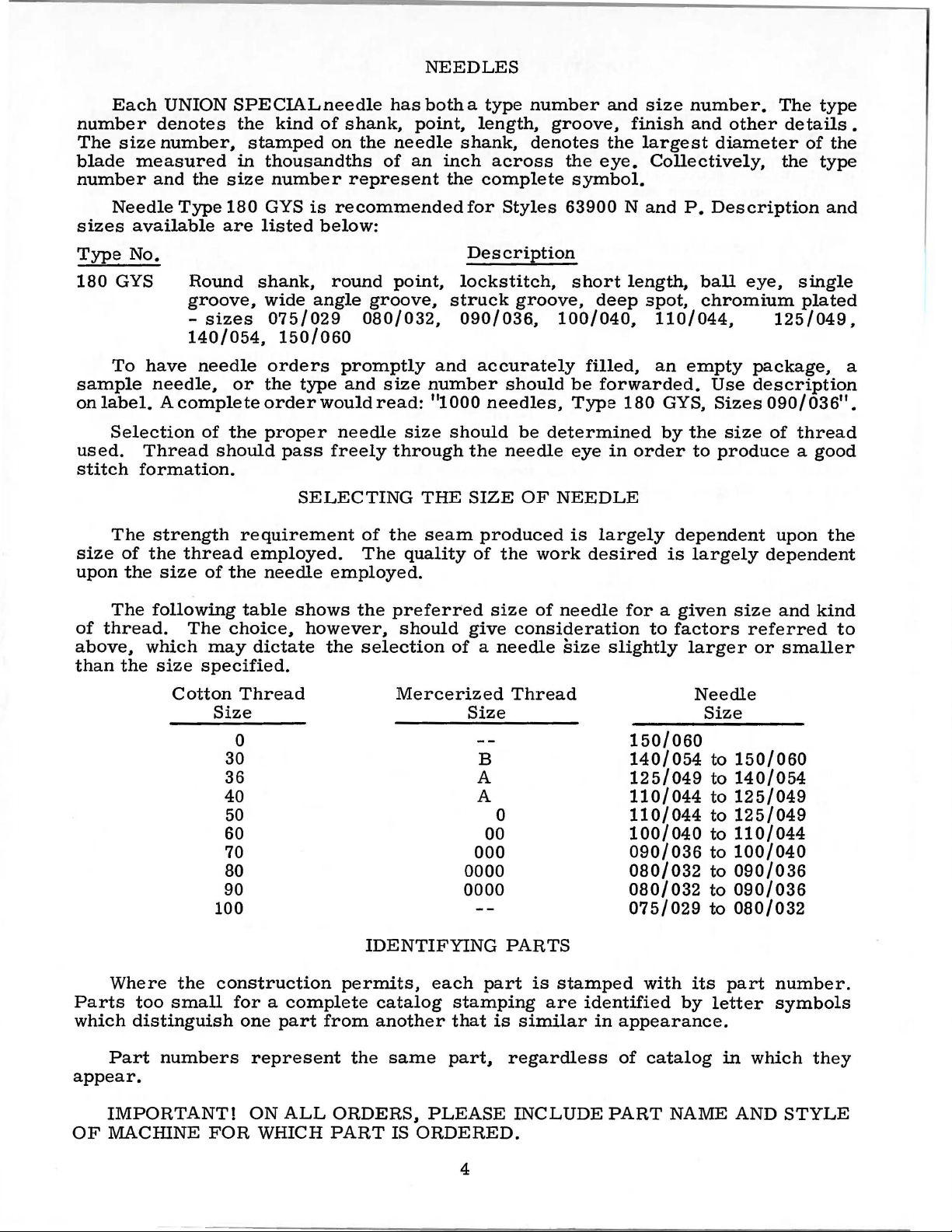
NEEDLES
Each
number
The
blade
number
Needle
sizes
Type
180
GYS
UNION
denotes
size
number,
measured
and
available
No.
the
Type
Round
groove,
140/054.
To
have
sample
on
label. A complete
needle,
Selection
used.
stitch
size
upon
Thread
formation.
The
strength
of
the
the
size
thread
SPECIALneedle
the
kind
stamped
in
thousandths
size
number
180
GYS
are
listed
shank,
wide
sizes
075/029
150/060
needle
or
orders
the
order
of
the
proper
should
pass
requirement
employed.
of
the
needle
has
of
shank.
on
the
needle
of
represent
is
recommended
below:
round
angle
point,
groove,
080/032,
promptly
type
and
size
would
read:
needle
freely
through
SELECTING
of
the
The
employed.
both a type
point.
shank,
an
inch
the
for
Description
lockstitch,
struck
090/036,
and
number
"1
000
size
should
the
THE
SIZE
seam
quality
number
length.
denotes
across
complete
Styles
groove.
accurately
should
needles.
be
needle
OF
produced
of
the
work
and
groove.
the
the
eye.
symbol.
63900
short
Nand
length,
deep
100/040,
filled,
be
forwarded.
Type
180
determined
eye
in
NEEDLE
is
largely
desired
size
number.
finish
and
largest
Collectively,
P.
Description
ball
spot,
chromium
110/044,
an
empty
Use
GYS,
by
the
order
to
dependent
is
largely
The
type
other
diameter
details.
of
the
the
type
and
eye,
single
plated
125/049.
package,
description
Sizes
size
090/03
of
thread
6".
produce a good
upon
the
dependent
a
The
of
thread.
above,
than
the
Where
Parts
which
Part
appear.
following
The
which
size
may
specified.
Cotton
Size
100
the
construction
too
small
distinguish
numbers
table
choice,
shows
dictate
however,
the
Thread
0
30
36
40
50
60
70
80
90
for a complete
one
part
from
represent
the
preferred
should
selection
Mercerized
IDENTIFYING
permits,
each
catalog
another
the
same
size
give
of a needle
of
needle
consideration
size
slightly
Thread
for a given
to
factors
larger
Needle
Size Size
150/060
B
A
A
0
00
000
0000
0000
140/054
125/049
110/044
110/044
100/040
090/036
080/032
080/032
075/029
PARTS
part
stamping
that
part,
is
are
is
similar
regardless
stamped
identified
in
appearance.
of
with
its
by
catalog
size
~
150/060
to
140/054
to
125/049
to
125/049
to
110/044
to
100/040
to
090/036
to
090/036
~
080/032
part
letter
in
and
referred
or
smaller
number.
symbols
which
kind
to
they
IMPORTANT!
OF
MACHINE
FOR
ON
ALL
WHICH
ORDERS,
PART
IS
PLEASE
ORDERED.
4
INCLUDE
PART
NAME
AND
STYLE
Page 5
ORDERING
OF
REPAIR
PARTS
The arrang
r
plac
eme
nt
parts
Two explod
list
ed
in
this catalog and
presents
On the
part
view being
a sector
page oppos
numbers,
shown.
Numbers
the
position
in
ordering
of the
parts.
exploded view
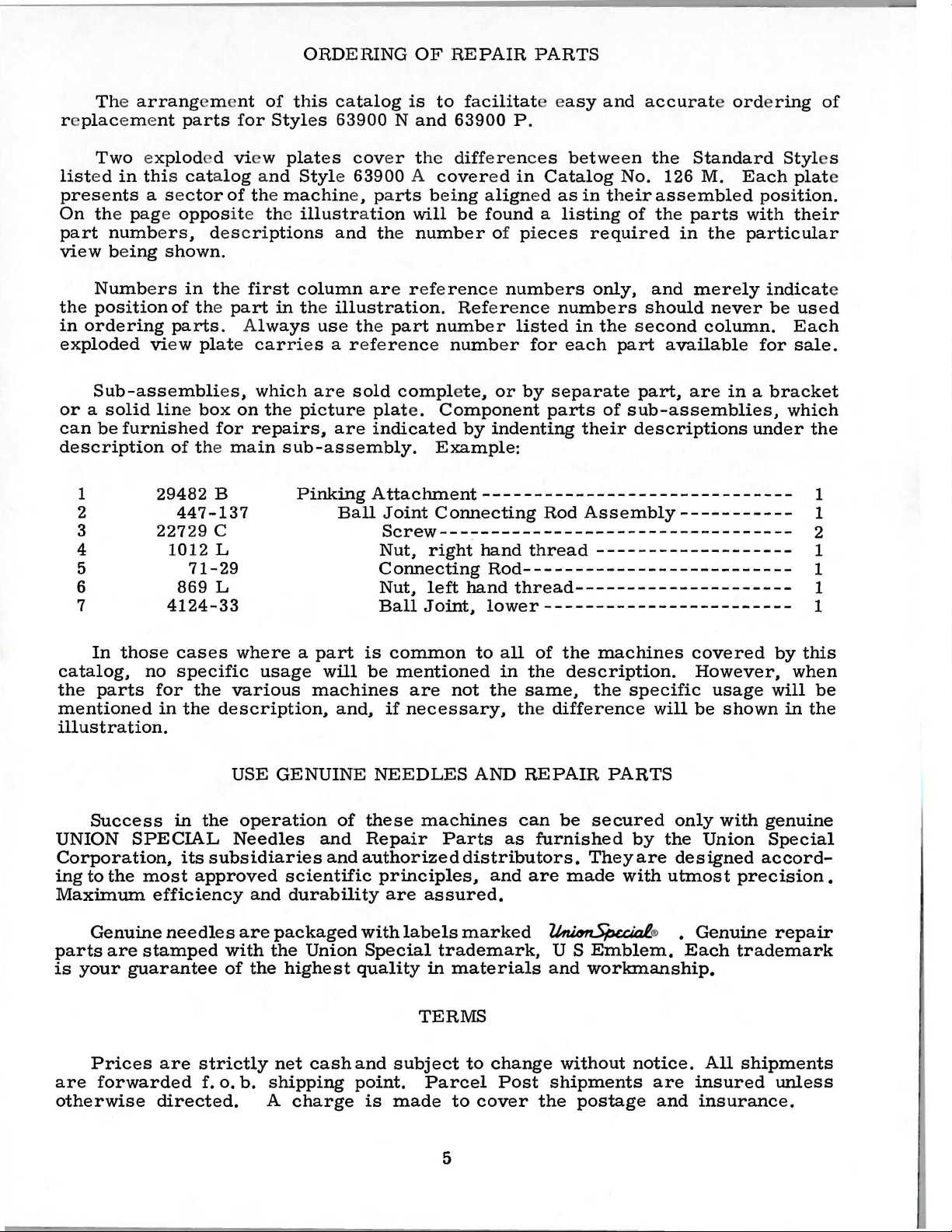
Sub-assemblies,
or a solid
can
be
description
1
2
3
4
line box
furnished
of the
29482
447-137
22729
1012
5
6
7
869
4124-33
em
nt
for
ed view
of the
ite the
des c r i
in the
first
part
A
plate carri
on
for
repairs,
main
B
c
L
71-29
L
of
this
catalog
Styles
plates
63900 N and
cov
Style 63900 A cover
machin
e, pa
illustration
ptions
and the
column are r efe
in the
lways
illustration.
use the
es a r efe r ence
which
the
are
picture
sold
are
sub-assembly.
is
to
er
the
rts bei
will
number
part
number
complete,
plat
e.
Component
indicated
Example:
facilitat
63900
diff
er enc
ed
ng
align
be
found a listing
of
e e
P.
es
in
Catalog
ed
pieces
asy
as
rence numbers
Ref
er e
nce
numbers
listed
numb
er
or
for
by
separate
each
parts
by
indenting
between
PinkingAttachment------------------------------
Ball
Joint
Screw---~------------------------------
Nut,
Connecting
Nut,
Ball
Connecting
right
hand
Rod--------------------------
left
hand
Joint,
lower------------------------
Rod
thread
thread---------------------
and
accurate ordering
the
Standard
No.
126
M.
in
their
required
only,
assembled
of
the
and
parts
in
the
merely
should
in
the
second
part
part,
of
sub-assemblies,
their
descriptions
column.
available
are
Assembly-----------
-------------------
Styl
Each
position.
with
particular
indicat
never
be
for
in a bracket
which
under
of
es
plat
their
used
Each
sale.
the
1
1
2
1
1
1
1
e
e
In
those
catalog,
the
parts
no
mentioned
illustration.
Success
UNION
SPECIAL
Corporation,
ing
to
the
most
Maximum
Genuine
parts
is
are
your
stamped
guarantee
Prices
are
forwarded
otherwise
cases
specific
for
the
in
the
description,
in
the
its
subsidiaries
approved
efficiency
needles
with
of
are
strictly
f. o.
directed.
where a part
usage
various
USE
GENUINE
will
machines
operation
Needles
and
and
scientific
and
durability
are
packaged
the
Union
the
highest
net
cashand
b.
shipping
A
charge
is
be
and,
if
NEEDLES
of
these
Repair
authorized
principles,
are
with
Special
quality
point.
is
common
mentioned
are
not
necessary,
machines
Parts
assured.
labels
trademark,
in
materials
TERMS
subject
Parcel
made
to
to
all
of
in
the
the
same,
the difference
AND
REPAIR
can
as
furnished
distributors.
and
are
marked
~
U S
and
to
change
Post
cover
shipments
the
the
machines
description.
the
specific
PARTS
be
secured
by
They
made
are
with
Emblem.
workmanship.
without
notice.
postage
will
only
the
designed
utmost
®
•
Each
are
and
covered
However,
usage
be
shown
with
Union
accord-
precision.
Genuine
trademark
All
shipments
insured
insurance.
by
this
when
will
be
in
the
genuine
Special
repair
unless
5
Page 6

INSTALLING
CAUTION!
on
handwheel.
and
the
Before
carefully
packing
leaving
box,
PREPARATION
A
bag
of
attaching
screw,
miscellaneous
Insert
the
upper
STANDARD
Included
ing
one
its
clamp
and
screw,
washers
up
the
hinge
frame
ACCESSORIES
also
bobbin
spring,
four
and
nuts,
machine,
When
Using
unpacking,
both
factory,
packed.
the
following
OF
MACHINE
assembly
one
extra
attachments
studs
eyelet
with
each
winder
one
assembly,
knee
isolator
and
After
parts,
in
holes
(A,
one
hands
each
the
steps
FOR
consisting
bobbin,
to
the
provided
Fig.
machine
lifter
assembly
pads
machine
DO
NOT
on
bed
UNION
machine
lift
casting,
SPECIAL
should
and
be
INSTALLATION
of
two
hinge
bed
plate,
for
2).
is a box
the
machine
of
and
and
clips,
rest
pin.
machine
lift
machine
accessories
followed:
one
frame
studs,
is
packed
them
in
STANDARD
mounting
its
rubber
one
chip
These
parts
out
of
gently.
thread
and
with
rear
of
frame,
pad,
chute,
are
box
by
placing
is
have
sewed
been
off,
removed
eyelet,
two
screws
each
cloth
machine.
plate.
ACCESSORIES-
one
oil
drain
bed
positioning
its
attaching
essential
when
one
inspected
from
one
eyelet
for
holding
Assemble
contain-
jar
spring
screws,
setting
hand
and
TABLE
the
TABLE
BOARD
TOPS
Lockstitch
bed
plate
machines
is
FLUSH
are
with
installed
the
top
of
in
the
table
tops,
machine
prepared
mounting
with
frame.
cut-out,
so
that
66
0 -1
68
6
Fig.
1
Page 7

INSTALLING
(Continued)
MACHINE
On a suitable
cut-out
through
over
the
nuts
with
left
right
retaining
lightly.
Place
1/16
inch
retaining
side
of
the
Tip
the
machine
fall
away
play
of
the
Before
lifter
rod
maximum
within
bar
the
raises
MOUNTING
table
the
hinge
hinge
hinge
pad
pad;
plate
sewing
head
clearance
plate
smartly
board
and
machine
mounting
from
cross
the
should
lift
head.
frame
the
shaft
machine
be
of
the
This
approximately
FRAME
board,
lugs
and
tighten
insert
(21393
in
the
between
upward
tighten
back
against
with
operator.
should
is
adjusted.
presser
may
place
to
the
round
R)
to
frame
the
locking
the
Assemble
put
The
bar
be
5/16
INSTALLATION
machine
rear
securely.
head
outside
mounting
(Fig.
Assembly
wood
front
mounting,
cloth
plate
with a hammer
nuts
securely.
the
rest
pin,
attaching
be
taken
into
production,
left
and
done
stop
its
by
holes
the
knee
up
by
screw
parts
setting
inch.
1 ).
screw
of
pan
and
edge
to
and
the
the
do
the
frame
Insert
the
bed
positioning
and
tighten
section,
after
and
being
the
insure a good
assemble
to
the
right,
press
cone
(22597
bell
not
stop
assembly
bearings,
crank
F)
interfere
screw
(213 93 U)
in
countersunk
spring
securely.
as
shown,
sure
frame
sides,
grip
chip
chute
so
that
as
shown.
but
must
(21665
should
be
with
so
that
the
wood
Assemble
and
there
on
the
(51278
the
chips
J)
of
set
so
moving
the
machine
screw
( 6 34 7 4 A)
snug
is
rap
up
about
the
under-
F)
to
will
All
end
not
bind.
the
knee
that
the
parts
presser
BOBBIN
The
located
when
allow
The
in
the
pulley
against
is
described
Catalog
BELTS
These
Thread
enlarged
CAUTION!
the
reservoir
WINDER
bobbin
winder
directly
operation.
mechanism
of
the
the
belt
under
No.
126
machines
machine
for
clarity.
Oil
must
in
front
The
winder,
to
wind
"Winding
M.
has
be
should
base
to
are
as
indicated
Needle
been
filled
be
of
the
of
be
moved
when
the
bobbin.
the
equipped
is
drained
before
secured
sewing
the
machine
winder
closer
in
operation,
Re~ulation
Bobbin',
to
use
THREADING
in
Fig.
threaded
OILING
from
starting
to
has
to
under
either
2.
from
the
to
the
table
belt
two
elongated
or
farther
should
and
OPERA
#1
"Vee"
Threading
left
to
main
operate.
top
so
and
will
away
exert
operation
TOR'S
or
at
right.
reservoir
that
bear
attaching
from
~nly
of
INSTRUCTIONS
round
check
before
its
puller
against
belt
enough
the
bobbin
belts.
spring
shipment
holes,
as
pressure
has
will
be
the
belt
which
needed.
winder
in
been
and
Fill
oil
is
be
added
straight
in
the
main
at
maximum
when
mineral
main
reservoir
level
needle
oil
of a Saybolt
reservoir.
at
when
is
inyellow
This
plug
needle
is
screw
band
(B,
is
in
marked
viscosity
equivalent
Fig.
yellow
of
to
7
2)
band
"LOW".
90
to
Union
and
125
Special
check
marked
oil
level
"FULL".
Use a stainless
seconds
at
specification
at
water-white
100°
Fahrenheit
gauge
Oil
should
No.
(C);
175.
Page 8

OILING
(Continued)
It
is
an
extended
of
the
needle
head
several
then
dial
clockwise
lever
bearings
cover
be
Oil
may
The
in
the
NOTE:
shaft
recommended
period,
bar
link,
as
no
minutes
expected
quantity
direction
direction
All
front
and
be
drained
moving
knife
to
without
of
and
holder
that a new
be
lubricated
take-up
further
distribute
damage.
from
oil
supplied
of
the
decreases
parts
rear,
shaft.
hand
oil
main
arrow
the
of
also
Fig.
machine,
by
removing
and
its
oiling
to
the
reservoir
to
the
(counterclockwise)
flow
pinking
oil
two
Major
oiling
2
or
lever
will
hook
of
attachment
oil
and
be
various
is
oil.
holes
points
8
one
that
the
head
needle
required.
parts.
by
removing
controlled
increases
to
for
lubricating
are
has
cover
bar.
Full
by
be
oiled
marked
been
and
Run
plug
out
oiling
After
machine
speed
screw
dial
(E).
the
once
both
in
red
of
the
oiling,
operation
(D,
Turning
oil
flow
daily.
sides
on
attachment.
service
bearings
replace
slowly
Fig.
and
Oil
of
for
for
can
2).
the
in
knife
lever
a
Page 9

SELF-PRIMING
HEAD
OIL
SIPHON
Class
the
machine
and
trickles
established.
twenty-four
which.
61494
Screw
666-214
Intake
of
L
Feu-----~~
63900
is
started.
down
it
is
machines
the
hours a day.
course.
far
are
oil
splashes
vertical
maintained
removing
exceeds
a:
~rq~
equipped
on
oil
tube.
unless
oil
the
rate
with a self-priming
the
thus
the
at
at
priming
priming
felt
the
rate
which
cup
is
removed.
of
six
oil
collects
the
head
felt.
siphon.
to
twelve
in
filters
Once
The
drops
the
oil
siphon.
through
siphon
head.
Retaining
the
per
61494
Oil
When
the
felt
prime
is
operates
minute.
N
Gromm
63494
et
D
Siphon
A
newly
machine
is
removed
should
function.
felt
block
do
not
correct
The
666-237.
felt
also
If
the
an
excessive
cup
felt
666-237.
be
installed
However.
the
siphon
felt
from
well
with
prevents
siphon.
INSTALLING AND MAINTENANCE
installed
is
operating.
from
the
be a distinct
determine
and
that
the
felt
in
the
is
to
meter
acts
as a filter
priming
amount
is
replaced
For
the
may
the
oil.
the
dry.
trapping
if
for
fail
cup.
In
The
siphon
However.
line
and
reduction
if
the
the
plastic
siphon.
priming
the
flow
and
cup
felt
of
lint.
by
removing
best
initial
intake
some
reason
because
.Then~
other
of
words.
air.
starts
the
of
siphon
tube
replace
cup
of
priming
keeps
and
the
it
may
self-priming
felt
air
is
while
and
its
action
it
may
siphon
the
oil
intake
is
the
is
tube.
connected
siphon
designed
oil
the
siphon
intake
be
necessary
access
is
replaced
the
priming
trapped
squeezing
squeeze
no
trouble
within
be
twenty
is
in
in
the
felts
and
clear
felt
plug
condition.
by
cup
in
the
the
out
the
should
OF
OIL
three
minutes
full
operation.
head
located
at
sump.
in
both
as
described
the
ends.
for a spe.cific
to
prevent
of
lint.
(666-214)
to
at
back
becomes
replace
of
machine
the
removing
felt
has
been
felt.
felt
As a precaution.
between
air
and
replace
be
experienced
SIPHON
to
five
or
Within
If
head.
If
purpose.
the
entrance
the
felt
the
end
oiled
the
minutes
so
before
an
hour.
the
siphon
is
inserted
the
above
below.
of
contaminated
felts.
and
of
replacing
the
siphon
The
cover.
before
fingers.
it
with
when
starting
after
all
the
there
does
in
two
items
This
felt.
air.
with
priming
should
installing.
remove
saturate
oil.
This
the
air
not
the
The
felt
the
it
the
9
Page 10

INSTRUCTIONS
FOR
ATTACHING
AND
ADJUSTING
PINKING
ATTACHMENT
Fig.
2 A
NOTE:
Styles
All
instructions
63900 N and
63900 B covered
a d d
it
ion
a 1
attachment.
ATTACHING
Check
lower
ing
(Fig.
and
to
ball
rod
assembly.
2A).
turn
obtain 1 29/32inch
Insert
in
end
of
(G)
against
Place
joint
tighten
(B)
screw
Insert
washer
screw
(M)
into
PINKING
the
joints
To
the
connecting
the
upper
pinker
the
washer
and
then
(K).
the
in
the
P
are
in
Catalog
instructions
ATTACHMENT
center
(A,
make
distance
B,
The
any
Fig.
distance
rod
dimension.
ball
driving
flat
(H)
on
shaft
ball
over
screw
large
base
base
hexagonal
of
pinking
of
machine.
pertaining
the
same
No.
126
pertain
between
2A)
of
should
adjustment,
(E)
in
the
Tightennuts
joint
(A)
into
(F)
and
stud.
ball
into
stud
the
head
attachment
to
the
as
those
M.
only
the
pinker
be 1 29/32
loosen
direction
the
tighten
of
the
pinker
screw
adjustment
for
The
following
to
the
pinking
the
upper
connect-
nuts
required
securely.
eccentric
set
lower
arm
(L)
and
(J)
and
tighten
of
Style
and
inch
(C,
D)
hole
screw
ball
and
its
SETTING
To
attachment
of
pink
NOTE:
point
may
bind
graph
SETTING
Set
Fig.
below
pinker
of
travel.
THE
set
and
of
pinking
and
"Setting
THE
the
2B)
so
top
edge
arm
the
to
The
upper
(B)
make a pencil
1/32
(Fig.
turn
tion
lowest
the
knife
of
inch
2B),
handwheel
until
point
1/32
so
it
lower
from
loosen
the
inch
coincides
knife.
WIDTH
width
the
to
it
Pinker
UPPER
its
point
of
is
For
line
in
pinker
of
pencil
Tighten
of
left
or
the
right
width
of
knife.
may
be
Driving
pinking
is
lower
at
its
lowest
this
on
upper
lower
screw
operating·
arm
travel.
line
with
OF
PINK
pink,
right
loosen
as
increases
pink
is
In
setting
necessary
Shaft".
KNIFE
knife
1/32
knife
(A,
inch
when
point
adjustment,
knife,
front
(C)
point
and
direc-
is
at
its
Now,
on
top
screw
set
upper
edge
(C).
screw
required.
the
measured
pinking
to
move
(L,
Fig.
Moving
width
from
of
the
attachment
the
pinker
2A)
base
pink.
center
for a wide
driving
and
to
the
Tighten
line
move
left
of
pink
shaft:
base
of
decreases
screw
the
needle
the
refer
pinking
width
securely.
to
the
ball
joint
to
para-
NOTE:
both
Knife
ends.
can
be
sharpened
on
10
Fig.
2 B
Page 11

TIMING
upper
top
advance
repositioning
Access
Fig.
loosen
wrench
moving.
feed
relationship
screws
The
knife
edge
2C).
dog,
THE
pinker
of
the
to
Using a 1/8
the
two
in
the
Turn
or
securely
PINKER
is
timed
(in
its
lower
material.
the
pinker
this
gear
screws
last
the
backward
mentioned
and
correctly
upward
knife
This
driving
is
obtained
inch
in
the
screw
loosened
handwheel
to
above
replace
travel)
when
hexagonal
retard
timing
hub
is
plug.
the
gear
of
forward
the
attained.
when
is
1/16
feed
can
on
by
removing
socket
driving
to
prevent
feed
the
inch
dog
be
the
gear,
to
advance
dog,
Tighten
point
changed
main
key
of
above
begins
plug
wrench
leaving
gear
until
the
the
to
by
shaft.
(A,
from
the
the
both
SETTING
Moving
margin
bind.
should
(B,
shaft
and
There
timing
NOTE:
a
full
described
To
be
Fig.
as
tighten
should
has
tooth
PINKER
the
may
The
cause
eliminate
relocated.
2C)
and
required
screws.
be
not
feed
above
on
page
pinking
loosen
and
no
been
dogs
the
27,
DRIVING
attachment
the
ball
this
bind
Loosen
screws
while
Push
end
changed.
throat
thrust
play
on
these
Catalog
SHAFT
joints
the
screws
holding
collar
in
the
FEED
machines
plate
at
126
to a wide
(A,
pinker
in
the
shaft
pinker
DOG
highest
M.
B,
in
thrust
hub
in
(N,
driving
should
pinking
Fig.
driving
collar
of
driven
position
Fig.
2A)
shaft.
HEIGHT
be
point
of
2A)
shaft
move
against
set
travel.
to
(N,
gear.
Check
to
Fig.
Move
gear
show
against
lug
and
to
at
Adjustment
Fig.
2A),
be
least
2C
remove
pinker
bed
tighten
sure
the
the
is
plug
driving
casting
screws.
pinker
depth
made
of
as
11
Page 12

Page 13

PINKER
THROAT
DRIVE
MECHANISM,
PLATES
AND
PRESSER
FEED
DOGS
FEET,
Ref.
Part
No. No.
1
2
3
4
5
6
7
8
9
10
11
12
13
14
15
16
17
18
19
20
21
22
23
24
25
26
27
28
29
30
31
32
33
34
61926
61928
63427-3
63430
63430
61330
63430
63430-3
22798
8-66
61926
61928
73 A
8-86
63427-2
63430
63430
61330
63430
63430-2
22798
8-66
63494
63479
22894
22525
63493
63479
22651
29475
22894
22894
22894
63479
N
N
A
E
B-39
B
p
p
A
E
B-35
B
B
F
J
c
A
E
CD-3
AZ
v
w
u
G
Description
Feed
Presser
Feed
Presser
Throat
63900
Presser
Spring
Hinge
Yielding
Presser
Screw
Presser
Throat
Screw
Chip
63900
Presser
Spring
Hinge
Yielding
Presser
Dog,
22
teeth
Plate,
Foot,
N
--------------------------------------------Foot
per
for
with
Style
bottom
inch,
63900
for
Style
N -
------------------------
marked 11AE-3
Shank---------------------------------
---------------------------------------------
Pin
------------------------------------------
Section-------------------------------------
Foot
Bottom,
marked 11AE-3
--------------------------------------------Foot
Dog,
Plate,
22
Guard
teeth
for
Style
---------------------------------
per
inch,
for
Style
63900 P -------------------------
---------------------------------------------
Guard
Foot,
p
----------------------------------------------
Pin-------------------------------------------
----------------------------------------with
bottom
Foot
Shank----------------------------------
marked 11AE-2
--------------------------------------------Section-------------------------------------
Foot
Bottom,
marked 11AE-2
Screw----------------------------------------------
Presser
Plug,
Pinker
for
pinker
Shaft
Foot
Driven
Guard
driving
Gear
--------------------------------gear
access
-------------------------------
Screw---------------------------------------------Screw,----------------------------------------------
Bed
Arm
Plug-----------------------------------------
Pinker
Main
Screw
Shaft
Shaft
Driving
Gear
------------------------------
--------------------------------------------Assembly
----------------------------------Screw---------------------------------------------Screw----------------------------------------------
SpotScrew------------------------------------------
Pinker
Driving
Shaft------------------------------------
63900 N ------------
11
,
for
Style
11
----------------
63900 P ------------
11
,
for
Style
11
----------------
hole
----------------
Amt.
Req.
1
1
1
1
1
1
1
1
2
1
1
1
2
1
1
1
1
1
1
1
2
1
1
1
2
3
1
1
2
1
2
1
1
1
36
37
38
63479
63479
63979
39
40
22730
41 63494 D
42
43
44
45
63479
21705
22894
46
47
*48
22657
61931
49
50
51
52
21393
SC182
51278
53 652
54
*Finger
guard
A
c
A
666-244
666-237
D
c
666-164
E-16
93
u
F
B-12
651 H
not
Pinker
Bushing,
Oil
Screw
Head
Bushing,
Thrust
Felt
Screw,
Finger
Screw,
Oil
Screw
Chip
Lock
Nut
furnished
Driving
Shaft
Sleeve
-----------------------------
right-----------------------------------------
Shield,
Felt
Oil
Siphon
Screw
Oil
for
pinker
Liner
-----------------------------------------------Siphon
Collar------------------------------------------
Wick,
for
----------------------------------------Assembly-------------------------------
Cup
Felt
left
------------------------------------------
--------------------------------------------for
pinker
driving
shaft
-------------------------------------
pinker
driving
driving shaft
shaft
bracket
Guard------------------------------------------
for
61414
Drip
Pan-------------------------------------------
------------------------------------------------
Disposal
A-------------------------------------
Chute------------------------------------
Washer------------------------------------------
--------------------------------------------------
with
machine,
available
as
extra
13
bracket
---------------
-------------------
------------------
send
and
charge
item.
1
1
1
1
1
1
1
1
1
2
1
2
1
1
1
2
1
2
2
Page 14

14
Page 15

PINKING ATTACHMENT
Ref.
No.
1 29482 B
2
3 22729 c
4 1012 L
5
6
7
8
9 39536
10
11
12
13
14 1776 L
15 18-71
16
17
18
19
20
21
22
23
24
25
26
27
28
29
30
31
32 18-422
33 14-171
34
35
36
37
38
39
40
41
42
43
44
45
Part
No.
447-137
71-29
869 L
4124-33
40-57
AD
1160 L
18-844
45-248
46-108
CS331
CS231
40-101
45-249
34-26
18-558
119-25
3-46
119-34
475-68
99-143
21210 A
810 L
99-329
40-86
18-353
76-18
1203 L
45-247
14-172
99-134
18-178
21-309
18-547
1012 L
18-501
40-46
18-544
Description
Pinking
Attachment,
Ball
Joint
Screw---------------------------------Nut,
Connecting
Nut.
Ball
VVasher------------------------------------VVasher-------------------------------------
----------------------------------------
Nut
Screw--------------------------------------
Lever,
Link,
Screw-------------------------------------Screw-------------------------------------Screw,
Nut,
VVasher-------------------------------------
Lever,
Cam
Screw,
UpperKnife--------------------------------Base---------------------------------------
Lower
Edge
Edge
VVasher-------------------------------------
Screw--------------------------------------
Holder
VVasher-------------------------------------
Screw ------------ -----Screw-------------------------------------Shaft,
Pinker
Screw,
PinkerArm---------------------------------
Shaft,
Holder.
Screw,
Flat
Screw-------------------------------------Nut
Attaching
VVasher------------------------------------Screw,
for
Throw-out,
Spring
----------------------------------------
Connecting
right
left
Joint.
for
throw-out
for
knife
for
4124-33
No.
for
knife
for
lower
Knife
Guide
Guide
-------------------------------------
for
base------------------------------
Handle-------------------------------
for
No. 14-171
for
lever-----------------------------
for
for
No.
Screw,
for
upper
complete
hand
hand
34-26
--------------------------------
---------------------------------
Holder---------------------------
upper
---------------------------------
thread
Rod--------------------------
thread---------------------
lower------------------------
throw-out---------------------
--------------------------
--------------------------
throw-out
for
upper
knife-----------------------
knife
14-172
for
No. 29482 B
knife-----------------------
--------------------
Rod
Assembly-----------
-------------------
------------------------
cam--------------knife
----------
----------------------
----------------------
-----------------------
--------------
--------
-------------
--
Amt.
Req.
1
1
2
1
1
1
1
1
1
1
1
1
1
2
1
1
1
1
1
1
2
1
1
1
1
1
1
1
1
1
1
1
1
1
1
1
1
1
1
2
1
1
1
1
1
15
Page 16

WORLD'S
FINEST
QUALITY
*
INDUSTRIAL
SEWING
MACHINES
UNION
SPECIAL
maintains sales
and
facilities throughout the world. These offices
aid
you
in
the selection of the right sewing
equipment for your particular operation. Union
and
Special representatives
tory trained
promptly
tion, there
and
and
is
a Union Special Representative to
serve you. Check with
ATLANTA,
BOSTON, MASS.
CHICAGO,
DALLAS, TEXAS
LOS ANGELES, CAL.
NEW
PHILADELPHIA,
GA.
YORK,
ILL.
N.
Y.
PA.
are
efficiently. Whatever your loca-
service men
able
to serve your needs
him
today.
MONTREAL, CANADA
TORONTO, CANADA
BRUSSELS, BELGIUM
LEICESTER,
LONDON,
PARIS, FRANCE
STUnGART,
service
will
are
fac-
ENGLAND
ENGLAND
GERMANY
Representatives
Industrial
and
cities
UNION SPECIAL
400
N.
FRANKLIN
dlatrlbuton
throughout
ST.,
In
all
Important
the
world.
CORPORATION
CHICAGO,
ILL.
60610
 Loading...