

Page 1
INDUSTRIAL
SEWING
FINEST
QUAliTY
STYLES
63900M
639001
63900W
63900AE
C 0 L U M B I A®
'·
MACHINES
CATALOG
No.
126R
··
CLASS
STREAMLINED
HIGH
TOP
AND
SPEED
BOTTOM
LOCKSTITCH
UNION SPECIAL
CHICAGO
63900
NEEDLE
ROLLER
FEED
FEED
MACHINES
CORPORATION
Page 2
Catalog
INSTRUCTIONS
No.
FOR
126
R
ADJUSTING
LIST
Needle
Top
and
63900
63900
CLASS
Feed
Bottom
Styles
M
w
First
AND
OF
Edition
OPERATING
PARTS
63900
Lockstitch
R.oller
63900
63900
Feed
T
AE
Rights
Union
Reserved
Copyright
By
Special
1966
Corporation
in
All
Countries
UNION SPECIAL CORPORATION
INDUSTRIAl
Printed
SEWING
CHICAGO
in
2
MACHINES
U.S.A.
Reprinted in 4/92
Page 3
The
predom-inant
machines
machines
gauges
1.
2.
insu:r;-ing
A
few
QUICK
The
average
box
to
STREAMLINED
idea
behind~®
in
the
world.
are a decidedachievement
complete
of
the
outstanding
INSTALLATION
installation
production
The
interchangeability.
sewing,
DESIGN
new
features
time
if
FOREWORD
high
installation
spe.ed,
along
are:
required
is
to
streamlined
these
lines.
will
be
instructions
build
Parts
about
the
Class
10
are
best
industrial
63900
are
made
minutes
followed.
lockstitch
to
precision
from
sewing
packing
Pleasing
gedness
is
more·
3.
SIMPLIFIED
Lubrication
for
trouble
system
reservoir,
ance.
4.
RAPID
Precision
oiling
higher
5.
FEED
Machines
the
stitch
It
is
which
SPECIALmachines.The
enables
in
appearance,
and
freedom
restful
OILING
of
these
free
provides
sealed
ACCELERATION
methods
system,
productive
REGULATING
are
fitted
length,
the
constant
customers
this
from
to
the
operator's
machines
operation.
long
hook
against
in
the
makes
plus a readily
aim
possible
rates
and
GEARS
with
feed
of
Union
to
procure
following
functional
difficult-to-clean
eye.
is
automatic.
A
completely
life.
lint
manufacture
lower
A
and
dust,
top
costs.
regulating
accessible
Special
all
pages
discuss
design
single,
reduces
of
operating
gears
to
furnish
possible
provides
recesses.
Oil
is
adjustable,
large
to a minimum
all
parts,
speed
for
means
advantages
valuable
for
concisely
greater
New
supplied
double
capacity,
coupled
almost
quick
Adjusting
and
adjusting
from
stability,
neutral
to
all
filtered
accurately
oiling
with
instantaneous
easy
prepared
the
the
and
Operating
adjustment
taupe
moving
hook
gauged
mainten-
an
advanced
needle
information
use
of
UNION
rug-
finish
parts
oiling
for
of
feed.
data.
Adjusting
call
attention
Illustrations
Exploded
name»
are
requirements.
follow
Union
anxious
Instructions
to
are
views,
the
Special
to
cooperate
for
many
used
Instructions.
representatives,
parts
to
pinpoint
together
in
Mechanics,
which
areas
with
to
planning
covering
must
explanations
be
under
and
meet
found
making
discussion.
in
Styles
exacting
as
to
all
leading
estimates
UNION SPECIAL CORPORATION
3
63900
conditional
quantity,
manufacturing
tailored
M,
T, W and
adjustments.
part
number
to
centers»
meet
AE»
and
your
Page 4

IDENTIFICATION OF
MACHINES
Each
stamped
standard
fixed,
Style
standard
"Style
Styies
number
Example: "63900".
This
listed
of
machines
back,
chine.
High
Light,
Horizontal
Adjusting
Automatic
Needle
Timing
Speed
UNION
into
and
but
never
numbers
machine,
63900
which
catalog
herein.
etc.,
Operating
Streamlined
Medium
Hook
Needle
Lubricating
Bearings
on
Upper
the
special.
contain
MZ".
of
differs
in
are
and
SPECIAL
name
contain
a
"Z"
machines
applies
It
can
this
given
direction
Heavy
Shaft,
Feed,
for
Shaft,
Class.
Take-up
machine
plate
Standard
the
from
also
from
Long
Gears
1
System,
Maximum Work
on
the
letter
letter
is
suffixed
similar
the
style
APPLICATION OF
specifically
be
Reference
the
of
STYLES
Arm
Duty,
1/4
Continuous
for
Inch
Head
Lever
is
identified
the
machine.
Style
"Z".
"Z".
to
in
construction
number,
applied
operator's
handwheel
OF
Needle
Changing
Needle
Oil
and
Space
Style
numbers
Example:
When
the
to
with
to
MACHINES
Feed
Siphon,
Needle
only
Standard
in
CATALOG
the
discretion
direction,
position
is
toward
Lockstitch
Running
Stitch
Bar
Travel,
Bar
to
Right
by a Style
numbers
have
Standard
one
"Style
minor
Style
are
grouped
that
Adjustable
it
such
while
the
Roller
Length,
One
Driving
of
Needle
number
are
or
more
63900
changes
number.
under
contains
Styles
to
some
as
right,
seated
operator.
Machines.
Feed,
Slotted
Reservoir
Hook
Link,
Bar 8 Inches.
which
classified
letters
M".
are
made
Example:
a
class
no
letter.
of
machines
Special
left,
at
the
One
Rotary
Segment
Enclosed
Oil
Control,
Needle
is
as
suf-
Special
in
Styles
front,
ma-
Needle,
Hook,
for
Feed
a
as
63900 M For
alls
of
hem . Maximum
63900 T For
men's
reaches
mum
recommended
63900 W For
to
sew
cation
63900
the
number,
measured
size
needles
recommended
are
AE
foot
Each
kind
number
Needle
listed
Same
of
stamped
in
packaged
making
and
dungarees.
making a 1/2
dress
over
301-SSa-1.
in
needle
below
pants,
machine
topstitching
belt
as
line
shank,
on
thousandths
represent
Type
for
Styles
3/8
recommended
inside
speed
loops.
Style
with
has
both
point,
the
and
sold
180
GVS
and
on
to
1/2
Seam
to 2 1/2
semi-dress
out.
5200
waistbands
Maximum
63900
centerline
a
type
length,
needle
of
an
the
complete
by
is
recommended
63900
the
next
inch
Specification
Fitted
W,
shank,
inch
UNION
T, W and
turned
speed
inch
pants
Seam
R.P.M.
on
with
recommended
except
of
needle
NEEDLES
and
groove,
across
symbol,
SPECIAL.
page.
down
301-EFb-1
5200
hem
Specification
twill
fitted
size
denotes
AE.
and
cloth
number.
finish
the
which
for
The
R.P.M.
turned
work
speed
hole.
Style
hem
by
pants.
and
woolen
plate
5200
with
The
and
the
largest
eye.
is
63900
descriptions
on
legs
inverted.
hand
301-EFb-1
extension.
spring
other
Collectively,
given
on
Sewn
pants.
R.P.M.
guide
type
diameter
on
M
and
of
overalls,
children's
when
or
number
details.
the
Type
and
Specify
garment
EFa-1.
Machine
Seam
keel
sizes
denotes
of
the
label
180
on
The
the
cover-
size
wear,
Maxi-
equipped
Specifi-
presser
size
blade,
type
available
of
GWS
and
all
is
Type
180
No.
GVS
Round
1/16
struck
125/049, 140/054,
shank,
inch
groove,
round
longer
than
deep
point,
standard,
spot,
150/060.
Description
lockstitch,
oversized
chromium
short
plated-
4
ball
length,
eye,
sizes
long
single
100/040,
blade,
groove,
110/044,
Page 5
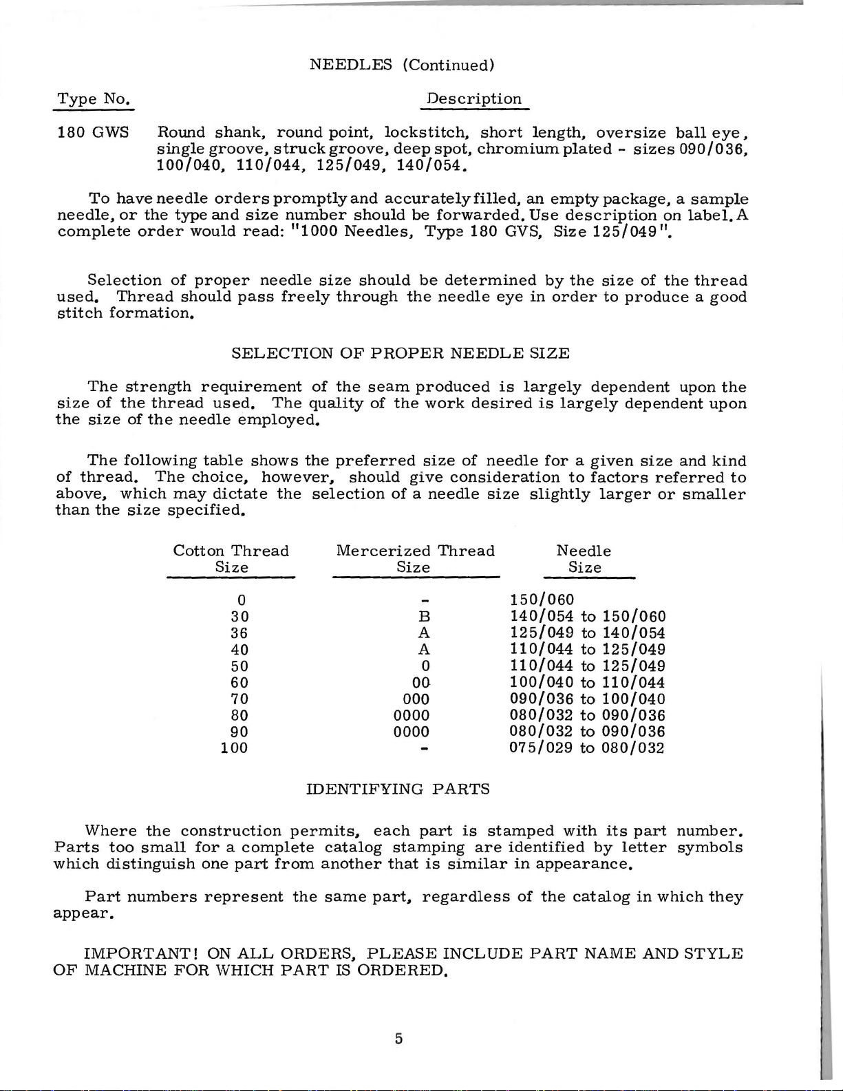
NEEDLES
(Continued)
Type
180
No.
GWS
To
needle.
complete
Selection
used.
stitch
formation.
The
size
of
the
size
The
of
thread.
above.
than
the
Round
single
100/040.
have
needle
or
the
order
of
Thread
strength
the
thread
of
the
following
The
which
size
specified.
shank,
groove,
orders
type
and
would
proper
should
requirement
used.
needle
table
choice,
may
dictate
round
struck
110/044,
125/049.
promptly
size
number
read: 111000
needle
pass
size
freely
SELECTION
of
The
quality
employed.
shows
the
however.
the
selection
point,
groove.
and
should
Needles,
should
through
OF
PROPER
the
seam
of
preferred
should
Description
lockstitch,
deep
spot,
140/054.
accurately
be
forwarded.
Typz
be
determined
the
needle
NEEDLE
produced
the
work
size
give
consideration
of a needle
short
chromium
filled,
180
GVS.
eye
is
desired
of
needle
size
length,
plated-
an
empty
Use
description
Size
by
the
in
order
SIZE
largely
is
largely
for a given
to
slightly
oversize
sizes
ball
090/036,
package, a sample
on
label.
125/049
size
to
dependent
11
•
of
the
thread
produce a good
upon
dependent
size
and
factors
larger
referred
or
smaller
eye,
A
the
upon
kind
to
Where
Parts
which
Part
appear.
Cotton
the
too
small
distinguish
numbers
Thread
Size
0
30
36
40
50
60
70
80
90
100
construction
for a complete
one
part
represent
Mercerized
IDENTIFYING
permits,
catalog
from
the
another
same
Size
00-
000
0000
0000
each
stamping
that
part,
Thread
B
A
A
0
PARTS
part
is
are
is
similar
regardless
150/060
140/054
125/049
110/044
110/044
100/040
090/036
080/032
080/032
075/029
stamped
identified
in
appearance.
of
Needle
Size
with
the
to
150/060
to
140/054
to
125/049
~
125/049
to
110/044
to
100/040
to
090/036
to
090/036
to
080/032
its
by
catalog
part
letter
in
number.
symbols
which
they
IMPORT
OF
MACHINE
ANT!
FOR
ON
ALL
WHICH
ORDERS,
PART
IS
PLEASE
ORDERED.
INCLUDE
5
PART
NAME
AND
STYLE
Page 6
ILLUSTRATIONS
The
arrangement
ordering
of
Class
of
63900
ORDERING
this
catalog
replacement
OF
REPAIR
is
to
parts.
PARTS
facilitate
easy
and
accurate
Eight
catalog.
ed
as
in
ened
area
machine.
of
the
pieces
exploded
Each
their
exactly
On
parts
required
Numbers
indicate
should
ed
in
number
never
the
for
the
second
each
Sub-assemblies,
a
bracket
or
sub-assemblies,
denting
bly.
18
19
ed
by
tion.
the
sary,
their
Example:
29126
22894
In
those
this
However,
specific
the
EL
J
catalog,
difference
view
plate
assembled
where
the
page
with
in
in
the
their
the
first
position
be
used
column.
part
a
solid
which
descriptions
Needle
Rod
Set
cases
where
no
when
u~age
will
plates
presents
position.
the
opposite
part
particular
column
of
the
in
ordering
Each
for
sale.
which
line
can
box
be
Feed
are
under
cover
a
sector
parts
the
numbers,
are
part
parts.
exploded
sold
on
the
furnished
the
Driving
the
of
Small
being
discussed
illustration
descriptions
view
being
reference
in
the
view
complete
picture
for
description
Eccentric
Standard
the
machine,
keyline
will
shown.
numbers
illustration.
Always
use
plate
or
by
plate.
repairs,
of
and
Styles
views
fit
in
be
and
the
carries
separate
Component
are
the
Connecting
Assembly----------------------------------------
Screw-----------------------------------------
a
specific
the
be
will
part
parts
mentioned
be
is
usage
for
shown
common
will
the
various
in
in
the
to
all
be
mentioned
the
description,
illustration.
of
the
machines
listed
parts
show
being
by a black-
the
assembled
found
the
number
only,
and
Reference
part
number
a
reference
part,
indicated
main
sub-assem-
machines
in
the
are
not
and,
in
a
listing
of
merely
numbers
are
parts
by
cover-
descrip-
the
if
neces-
this
align-
list-
in
of
in-
1
2
same,
At
the
parts
and
shown
description
Success
genuine
UNION
Corporation,
signed
with
according
utmost
Prices
All
shipments
are
insured
postage
and
back
in
of
this
when
in
the
SPECIAL
its
subsidiaries
to
precision.
are
strictly
are
forwarded
unless
otherwise
insurance.
the
book
book.
only
the
USE
operation
repair
the
most
Maximum
net
will
This
will
part
GENUINE
of
these
parts
and
approved
efficiency
TERMS
cash
f.o.b.
directed.
be
found
facilitate
number
REPAIR
machines
as
furnished
authorized
scientific
and
subject
shipping
A
6
a
numerical
is
known.
PARTS
distributors.
and
durability
to
point.
charge
locating
can
be
by
the
principles,
change
Parcel
is
made
index
the
secured
Union
They
are
without
Post
to
cover
of
all
the
illustration
only
with
Special
are
and
are
made
assured.
notice.
shipments
the
de-
Page 7

UNPACKING
CAUTION!
Using
packed.
steps
STANDARD
eyelet,
base
(1)
extension
pivot
for
both
Before
After
should
Included
(1)
plate,
can
of
Included
Included
Included
brackets,
pivot
oil
and
pin
When
unpacking,
hands
screw
(1)
on
bed
leaving
be
ACCESSORIES
with
and
also
also
also
and
the
machine
followed:
each
for
knee
(1)
with
with
(3)
screws
with
(1)
(1)
the
upper
press
extra
Style
folder
rock
casting,
factory,
and
machine
frame
rod,
bobbin.
Style
Styles
for
actuator
shaft
DO
lift
each
accessories
is a box
eyelet,
(1)
bobbin
63900 T is
63900 W and
cloth
plate
63900 M is
finger,
connecting
NOT
gently.
Union
(1)
winder
(1)
extension.
(1)
(1)
of
front
arm.
INSTALLING
lift
m?.chine
Special
have
standard
base
bell
63
900
pivot
machine
been
plate,
assembly,
crank
AE
is
pivot
bracket,
pin
out
of
box
removed
accessories
(1)
hook
(2)
actuator
(1)
bell
for
folder
is
sewed
from
screws
rod.
crank
(1)
actuator
by
oil
rear
placing
off,
the
packing
--
containing
return
for
actuator
pivot
finger,
one
hand
inspected
channel,
bobbin
rod,
bracket,
box,
(1)
winder
(2)
retaining
on
handwheel.
and
the
upper
(3)
screws
asserpbly,
(1)
cloth
(2)
screws
carefully
following
frame
for
plate
for
rings
650
21661
==:~
These
AC
and
-36
~:
p..:.._
are
(4
*
___
parts
not
Fig.
'
are
components
furnished
1
with
of
1400 D pedestal
the
machine.
660-168
Cushion
69
FD
664
Screw*
J
7
Page 8

PREPARATION
Before
machine.
Style
and
21662
the
bottom.
pin
(21664
base
plate
hook
oil
to
hold
Styles
{21680
(63996)
used
to
NOTE:
the
machine
machine
The
63900 M {Fig.
AE)
Now
J).
now
return
the
base
63900
AX)
to
is
mounted
hold
the
Cloth
is
PREPARATION
The
pedestal
the
hemmer,
be
accomplished
The
pedestal
knee
final
press
adjustment
assembly
al.
the
ment
the
for
Place
pedestal
On
"S"
lifting
of
the
the
Style
hook
the
so
knee
to
OF
machine
on
top
assemble
Snap
can
channel
plate
T,
the
bottom
base
plate
set
OF
for
in
the
after
for
of
four
the
press
63900
the
presser
MACHINE
can
be
also
1)
of
the
retaining
be
assembled
{63996)
to
the
63900
of
under
the
plate.
extension
on
the
pedestal,
PEDESTAL
Style
left
hole
the
machine
Styles
for
lifting
the
knee
isolators
four
holes
assemblies
M, a
treadle
chain
hook
foot
INSTALLING
FOR
INSTALLATION
placed
has
is
folder
to
prepared
base
rings
is
onto
be
prepared,
plate
actuator
{660-254
to
the
under
machine.
Wand
63900
machine,
base
Attach
using
plate
upper
{63982
using
FOR
INSTALLATION
63900 M {Fig.
of
the
pedestal.
has
63900
press
the
assembly
{51295
in
base
T,
63900
presser
B)
can
and
chain
on
the
underside
can
also
be
the
pedestal,
by
mounting
(21680
AX),
finger
D)
machine~
the
base
AE
{Fig.
three
and
is
held
frame
E)
three
1)
can
screws
is
prepared
eyelet
Final
been
placed
Wand
foot,
will
be
in
the
recesses
plate
align
now
be
made.
is
required
used
for
Styles
(Continued)
the
prior
to
the
using
{21665 H)
onto
using
plate
2)
are
screws
in
be
mounted
adjustment
on
the
63900
in
the
after
with
the
of
bed
63900
pedestal
being
front
two
between
the
pivot
three
and
is
prepared
(22652
position
(A,
Fig.
{22517
by
mounting
pedestal.
AE
left
hole
the
machine
of
the
pins
to
lift
plate
T,
has
to
placed
and
rear
screws
the
pin
and
screws
attached,
by
merely
D-8).
by
the
3)
using
on Sty
le
B).
the
of
the
{Fig.
of
2)
the
has
pedestal.
in
the
the
presser
at
the
back.
63900 W and
be
prepared
on
the
pedestal.
pivot
{22517
two
brackets
B)
brackets,
locate
(22652
using
D-8),
the
mounting
The
hook
left
hand
screw
screw
(22570
63900 W and
knee
press
knee
press
is
prepared
pedestal.
been
placed
Now
place
isolators.
foot
and
The
treadle
63900
coming
in
being
left
oil
return
63900
assembly
by
Once
on
the
The
roller.
AE,
to
receive
(21662
up
using
grooves.
sure
screw
the
base
marked
A).
AE
for
collapsing
mounting
again,
the
machine
final
mechanism
if
desired.
the
AF
from
pivot
The
the
used
plate
channel
"X"
after
will
the
the
pedest-
on
adjust-
Attach
~'
These
parts
and are
8
not
are
components
furnished
with
of
1400 D pedestal
the
machine.
Fig.
2
Page 9
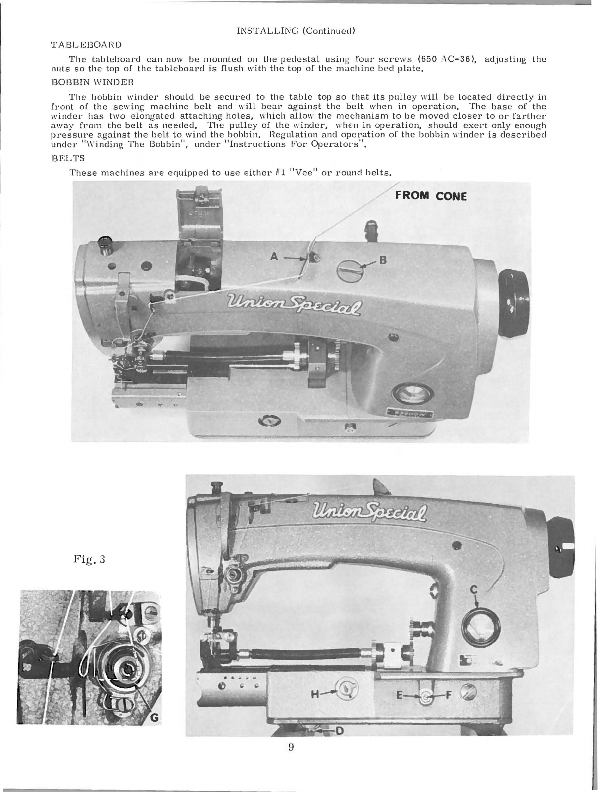
TABU::BOAI~D
The
so
the
The
of
has
from
"Winding
These
tableboard
top
of
\\'INDEH
bobbin
the
sewint;
two
the
belt
against
machines
nuts
BOBBIN
front
winder
away
pressure
under
BELTS
can
the
tableboard
winder
machine
elongated
as
the
beLt
The
Bobbin",
are
now
be
should
attaching
needed,
to
wind
equipped
mounted
is
be
belt
The
the
under
to
INSTALLING
on
flush
with
secured
and
\\ill
holes,
pulley
bobbin.
"Instructions
use
either
the
pedestal
the
to
the
bear
\\
hich
of
the
Hegulation
Il l
(Continued)
top
of
table
against
allo\\'
\\'indcr,
For
Operators".
"Vee"
using l'our
the
machine
top
so
that
the
belt
the
mechanism
\\he-n
and
operation
or
round
screws
b0d
its
when
in
operation,
belts.
(650
plate.
pulley
in
to
be
of
the
AC-36),
will b Located
operation.
moved
should
bobbin
FROM CONE
The
closer
exert
winder
adJusting
directly
base
to
or
farther
only
enough
is
described
of
the
in
the
Fig.
3
9
Page 10

LUBRICATION
CAUTION!
the
reservoir
Lubricate
and
speed
run
slowly
operation
must
machine
RECOMMENDED
Use a stainless
125
seconds
Special
check
marked
_
It
an
extended
oil
the
Replace
Oil
OIL
GAUGE
The
Should
oil
is
an
at
specification
level
"FULL".
recommended
period,
bearings
end
cover,
may
oil
be
gauge
adjustment
Oil
has
be
for
several
can
then
OIL
water-white
100°
at
gauge
Oil
of
the
as
drained
is
set
been
filled
before
thoroughly,
minutes
be
expected
Fahrenheit
No.
175.
(C):
should
be
that a new
be
lubricated
needle
no
further
from
at
the
become
drained
straight
in
the
Fill
oil
is
at
added
machine,
as
bar
hand
main
factory
necessary,
from
starting
in
accordance
to
distribute
without
mineral
main
main
reservoir
maximum
when
follows:
link,
the
oiling
reservoir
to
show
the
main
to
operate.
the
damage.
oil
reservoir.
level
needle
or
one
Remove
take-up
will
be
by
removing
the
the
following
reservoir
with
instructions
oil
to
of a Saybolt
This
at
plug
when
is
in
yellow
that
has
the
and
required.
proper
oil
steps
the
is
screw
needle
band
been
head
its
lever
plug
level
before
which
various
viscosity
equivalent
(B,
is
in
marked
out
of
cover
and
screw
in
the
should
shipment
follow,
parts.
of
to
Fig.
3)
yellow
"LOW".
service
and
directly
needle
(D,
Fig.
reservoir.
be
followed:
and
Full
90
to
Union
and
band
for
bar.
3 ).
1.
2.
3.
4.
5.
Place
Remove
bottom
Oil
should
below
Loosen
right
so
Tighten
the
the
of
the
lock
the
lock
machine
reservoir
the
machine).
be
added
bottom
nut
(E,
gauge
nut
upright
edge
needle
and
plug
or
removed
of
the
Fig.
3)
replace
on a level
screw
hole.
on
the
rests
on
plug
table
(located
so
that
calibrating
the
yellow
screw.
the
or
below
oil
band
bench.
level
screw
marked
the
handwheel
is
approximately
(F),
and
"FULL".
turn
and
screw
on
gauge
near
1/8
left
the
inch
or
(C).
10
Page 11
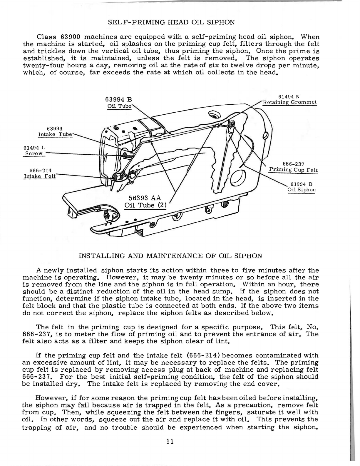
SELF-PRIMING
HEAD
OIL
SIPHON
Class
the
machine
and
trickles
established,
twenty-four
which,
61494
Screw
of
L
--------------~~~~~
63900
is
started,
down
it
is
machines
the
maintained,
hours a day,
course,
far
are
oil
splashes
vertical
removing
exceeds
equipped
on
oil
tube,
unless
oil
the
rate
with a self-priming
the
thus
the
at
at
priming
priming
felt
the
which
rate
cup
is
removed.
of
six
oil
collects
the
felt,
siphon.
to
twelve
head
filters
The
in
the
oil
siphon.
through
Once
siphon
drops
head.
the
per
61494
When
the
felt
prime
operates
minute,
N
6:l994
OilS
phon
is
8
A
newly
machine
is
removed
should
function,
felt
block
do
not
The
666-237,
felt
also
If
the
an
excessive
cup
felt
666-23
be
installed
However,
the
siphon
from
oil.
cup.
In
trapping
INSTALLING
installed
is
operating.
from
be a distinct
determine
and
that
correct
felt
is
acts
the
in
the
to
meter
as a filter
priming
amount
is
replaced
7.
For
the
dry.
if
for
may
fail
Then,
other
of
words,
air,
the
line
reduction
if
the
siphon,
priming
the
cup
of
by
best
The
some
because
while
squeeze
and
siphon
However,
and
the
siphon
plastic
replace
flow
and
felt
and
lint,
removing
initial
intake
reason
squeezing
no
trouble
AND
MAINTENANCE
starts
it
the
siphon
of
the
intake
tube
is
the
cup
is
of
priming
keeps
it
the
may
the
intake
access
self-priming
felt
is
the
air
is
trapped
the
out
the
should
its
action
may
be
is
oil
in
tube,
connected
siphon
designed
oil
siphon
felt
be
necessary
plug
replaced
priming
felt
between
air
and
be
OF
within
twenty
in
full
the
minutes
operation.
head
located
at
both
felts
as
for a specific
and
to
prevent
clear
of
(666-214)
to
at
back
condition,
by
removing
cup
felt
in
the
felt.
the
replace
experienced
OIL
SIPHON
three
to
or
five
so
Within
sump.
in
ends.
described
the
If
the
head,
If
the
below.
purpose.
the
entrance
lint.
becomes
replace
of
the
has
the
machine
felt
the
been
oiled
felts.
of
end
As a precaution,
fingers,
it
with
when
saturate
oil.
starting
minutes
before
an
siphon
is
inserted
above
This
after
all
hour,
does
two
felt»
of
air.
contaminated
The
priming
and
replacing
the
siphon
cover.
before
installing,
remove
it
well
This
prevents
the
siphon.
the
the
air
there
not
in
the
items
No.
The
with
felt
should
felt
with
the
11
Page 12

THREAD
INSTRUCTIONS
FOR
OPERATORS
While
of
the
the
direction
of
each
WINDING
Thread
from
down
post.
(B).
bobbin a few
downwardly
into
position.
will
automatic
pulley.
be
between
up
contact
be
varied
hook
hand.
Fig.
the
Press
to
rotated
The
the
THE
supply
the
When
throw-out
by
direction
rotation
of
twist.
Turn
5
BOBBIN
the
bobbin
down
the
tension
an
empty
stop.
turns
on
with
extent
regulating
in a clockwise
hand
machine
the
and
of
the
favors
grasp a short
the
thread
unwind.
REMOVING
direction
the
machine.
the
the
be
winder
through
discs.
bobbin
wind
lever
machine
filled
member.
to
the
belt,
until
which
the
twist
the
use
away
To
remove
left
hand,
bobbin
Opening
latch
removed.
by
the
and
on
end
direction
(D)
until
and
is
operated.
the
which
the
bobbin
screw
in
the
of a left
length
from
it
is a left
THE
until
open
case
the
is
closed.
leading
eyelet
under
the
of
thread
pulley
is
locked
thread
disengages
(C).
bobbin
twist
of
you
BOBBIN
the
bobbin
needle
reach
the
bobbin
out
latch
the
(A,
the
winder
and
is
the
engages
is
filled
thread
thread
thread
with
twist.
case.
reaches
in
under
of
the
retains
the
bobbin
thread
Fig. 6 ).
tension
shaft
around
press
moved
in
that
bobbin
the
the
can
is
in
between
your
if
not.
CASE
turn
its
the
case
sewing
the
is
immaterial.
the
needle.
thumb
right
latch
hand.
it
handwheel
highest
throat
(A.
hook.
bobbin
released
is a right
plate
and
If
position.
Fig.
in
the
and
the
direction
To
determine
forefinger
the
in
operating
at
left
5).
case.
can
strands
twist.
Using
end
and
pull
When
readily
of
The
base.
ing
wind
all
and
machine
and
screw
unevenly
The
times.
begin
tension
can
purpose
is
be
(E)
so
may
When
to
wind
sewing.
Fig.
post
shifted
that
of
the
7
bracket
be
readily
the
bobbin
the
from
any
tendancy
bobbin
empty
is
mounted
left
to
right
of
corrected.
winder
in
the
machine
one
immediately.
THREADING
The
the
thumb,
hand.
The
thumb
coming
on
the
by
the
is
to
bobbin
forefinger
bobbin
and
forefinger
off
the
12
winder
loosen-
bobbin
assure
is
used
THE
case
(B)
bottom
to
up.
Bobbins
BOBBIN
(A.
itself
an
replace
Fig.
and
of
of
the
operator
can
be
CASE
7)
should
second
should
the
right
bobbin.
Fig.
of a full
it
with
rewound
be
finger
be
held
hand
6
bobbin
the
full
while
held
between
of
the
between
with
at
one.
the
LEFT
the
thread
Page 13

INSTRUCTIONS
FOR
OPERATORS
(Continued)
THREADING
Place
finger
Fig.
8)
direction
at
the
the
of
right
under
of
bobbin
Fig.
the
handwheel.
The
cross
(A,
Fig.
as
far
mulated
as
lint
9 )1 is
it
THE
bobbin
hand~
the
the
case
8
hole
will
from
BOBBIN
in
draw
tension
rotation
from
REPLACING
and
latch
the
be
be
INSERTING
with
Tighten
in
to
show
go
and
1
needle
CASE
bobbin
the
spring
of
the
the
Have
one
should
throat
placed
released
Insert
the
set
the
needle
the
to
(Continued)
case.
bobbin
bobbin
back.
the
half
plate
part
the
spot
screw
In
one
thread
(B)
and
as
The
bobbin
THE
BOBBIN
needle
inches
be
opened
and
way
and
bobbin
THE
NEEDLE
needle
(sometimes
securely.
into
the
bar
through
into
bar1 about
operator
when
provide a means
hole
so
the
needle
continuous
through
self
threading
end
of
should
CASE
at
its
of
thread
with
the
the
sewing
case
into
the
called
1/4
needle
for
will
motion1 with
diagonal
the
thread
rotate
highest
to
hang
left
hand1 and
the
bed
hook.
snapped
needle
scarf)
inch
from
has
been
cleaning
seat
thumb
slot
in
bobbin
slot
(C)
on
is
pulled
when
counterclockwise.
position1 allow
free.
plate
into
bar
toward
the
The
position.
The
by
reaching
extension~
latch
as
far
the
right1 facing
end
inserted
the
accu-
properly.
and
case.
about
bobbin
it
should
as
it
A
fore-
case
Note
looking
two
case
under
should
then
will
(A
go
1
1
THREADING
Threading
thread
the
passes.
needle
eye
PREPARATION
With
the
handwheel
highest
it,
through
your
position.
the
foot.
--.: •
..,,~
Fig.
tension
bobbin
this
adjustment
1 0
on
the
suspended
THE
NEEDLE
diagram
Please
from
left
FOR
left
hand1 hold
in
operating
Pull
needle
TENSIONS
B A
.,.
thread
sewn.
on
BOBBIN
screw
spring
by
check.
(Fig.
note
to
right.
SEWING
direction
up
the
hole
in
perfect
are
A
both
threads.
THREAD
The
tension
(A,
is
correct
the
bobbin
3)
that
the
needle
the
locked
stitch
Fig.
when
shows
the
end
of
until
thread
throat
stitch
of
this
TENSION
on
10)
it
thread.
the
places
needle
the
needle
the
and
plate.
is
one
together
kind
the
bobbin
which
is
just
The
where
thread
passes
thread1 leaving
needle
Draw
in
in
is
the
bobbin
both
which
the
secured
moves
center
case
regulates
sufficient
thread
should
the
threads
the
is
applied
the
to
needle
through
down
thread
needle
of
by
regulating
tension
hold
not
it
slack1 and
and
will
under
thread
the
material
by
spring
the
bobbin
be
in
Fig.
up
again
come
the
and
the
means
the
eyelet
9
turn
to
up
with
presser
bobbin
being
tensions
of a set
(B).
The
case
its
and
for
13
Page 14
INSTRUCTIONS
FOR
OPERATORS
(Continued)
BOBBIN
THREAD
Remove
turn
set
to
apply
release
When
rarely
as
varying
screw
more
tension.
the
becomes
attain a good
NEEDLE
The
the
tension
the
nut
tension,
This
in
its
the
machine
THREAD
needle
in a clockwise
while
should
raised
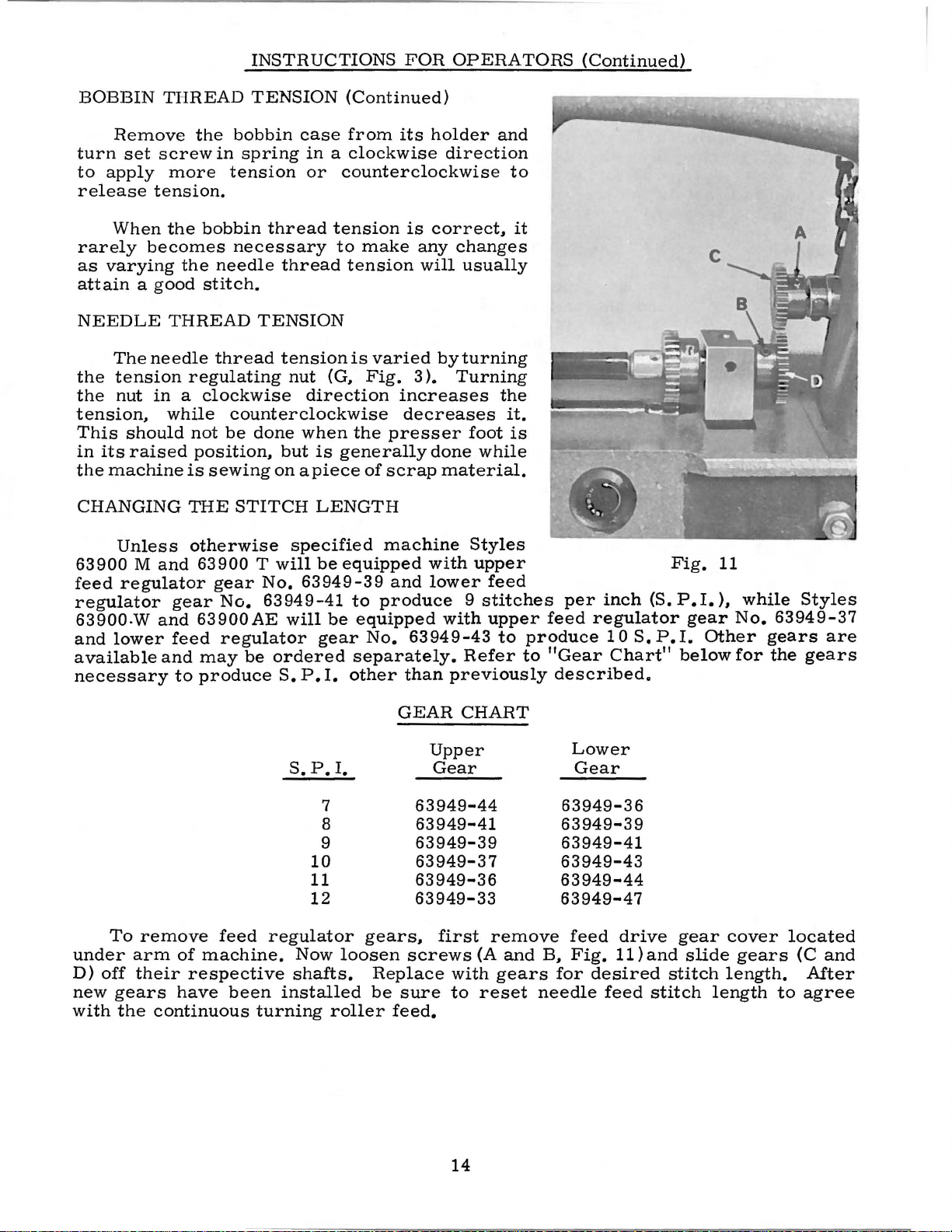
CHANGING
Unless
63900 M and
feed
regulator
regulator
63900.W
and
lower
available
necessary
gear
and
feed
and
to
the
bobbin
in
spring
tension
bobbin
necessary
the
needle
stitch.
thread
regulating
counterclockwise
not
be
position,
is
sewing
THE
STITCH
otherwise
63900
gear
No.
63900AE
regulator
may
be
produce
TENSION
case
in a clockwise
or
thread
thread
TENSION
tensionis
nut
(G,
direction
done
but
on
when
is
apiece
LENGTH
specified
Twill
No.
be
63949-39
63949-41
will
be
gear
ordered
S.
P.
I.
(Continued)
from
its
holder
direction
counterclockwise
tension
to
tension
make
varied
Fig.
is
correct,
any
will
byturning
3 ).
changes
Turning
increases
decreases
the
presser
generally
of
scrap
done
material.
machine
equipped
to
produce 9 stitches
equipped
No.
with
and
lower
63949-43
with
separately.
other
than
previously
and
to
usually
the
it.
foot
is
while
Styles
upper
feed
upper
to
Refer
it
feed
produce
to
"Gear
described.
per
regulator
inch
10
S.
Chart"
(S.
P.
. • •
..
" . \
~-"· . ~
~
.:
Fig.
P.I.
gear
I.
Other
below
11
),
'1,
......
...
---c
while
No.
for
A
:.
•. -·:
~ .·~
,, ,.
.
p
""'~.~
..
~
~a..t
~
..
_1\
.,_,
Styles
63949-37
gears
the
are
gears
•
under
D)
off
new
with
To
remove
arm
their
gears
the
feed
of
machine.
respective
have
been
continuous
S.
P.
10
11
12
regulator
Now
shafts.
installed
turning
I.
7
8
9
loosen
roller
GEAR
63949-44
gears,
screws
Replace
be
sure
feed.
CHART
Upper
Gear
Lower
Gear
63949-36
63949-41
63949-39
63949-39
63949-41
63949-37 63949-43
63949-36
63949-33
first
(A
with
to
reset
remove
and
gears
63949-44
63949-47
feed
B,
Fig.
for
needle
drive
11)and
desired
feed
gear
slide
stitch
stitch
cover
gears
length.
length
located
(C
After
to
agree
and
14
Page 15

INSTRUCTIONS
FOR
MECHANICS
TIMING
Fig.
THE
NEEDLE
12
FEED
and
WITH
loosen
connection
per
inch
arm
entric
the
bottom
the
timing
hub
coincide.
Rotate
its
stroke.
not,
forward
making
needle
To
drive
designated
Vary
of
needle
thickest
Open
top
of
at
letter
Loosen
(D).
loosen
or
sure
bar
set
segment
the
needle
deflection
section
THE
CONTINUOUS
cover
needle
stud
needle
two
(C)
11811
frame
•
set
Rotate
of
its
stroke.
line
(E)
Tighten
handwheel
The
needle
clamp
backward
all
side
frame
needle
and
feed
locking
letter
travel
to
(A,
to
point
feed.
screws
the
handwheel
on
the
all
until
screw
until
play
the
with
nut.
on
segment
when
be
sewn.
Fig.
drive
of
This
on
12)
segment
maximum
would
the
Rotate
connecting
screws.
the
bar
should
(F)
and
bar
is
removed
segment.
roller
Set
so
as
to
the
needle
TURNING
in
the
head
locking
locate
needle
until
the
the
eccentric
arm
needle
bar
be
move
is
vertical.
feed
loosen
connection
for
approximate
obtain
enters
ROLLER
of
number
the
frame
needle
and
the
is
vertical.
needle
Tighten
from
between
needle
toward
the
least
or
FEED
the
machine
nut
(B).Set
of
stitches
connecting
drive
bar
only,
eccentric
at
bottom
If
bar
frame
screw,
frame
higher
setting.
amount
leaves
eccis
at
until
of
it
is
the
the
PRESSURE
The
only
enough
work
the
Fig.
gulator
feed
presser
17)
in a clockwise
counterclockwise
SETTING
The
lower
to
which
at
the
frame
is
2 1 I 4
used
fer
red
length
Styles
factory.
(A,
inches.
The
in
setting
to
The
two
needle
63900
the
four
ON
MATERIAL
presser
pressure
uniformly.
foot,
THE
NEEDLE
end
needle
The
Fig.
13)
lines
needle
as
TIMING
lower
Type
M,
spring
on
To
turn
of
the
bar
distance
to
the
engraved
LINES.
lines
180,
63900
(A,_
the
feed
increase
presser
direction.
decreases
BAR
needle
is
timed,
bottom
bar
are
which
T,
63900 W and
Fig.
spring
TO
from
on
to
height,
used
is
17)
should
rollers
the
to
pressure
regulator
Turning
the
pressure.
HEIGHT
bar
frame,
is
faced
the
bottom
of
the
throat
the
needle
and
with
the
recommended
63900
exert
make
the
the
to
height
of
bar
are
short
the
on
(
B,
re-
one
the
plate
are
re-
for
AE.
the
with
When
upper
the
the
timing
lower
needle
line
edge
of
bar
(B,
the
is
Fig.
lower
at
its
13)
needle
lowest
should
bar
position,
be
EVEN
frame
(A).
15
Fig.
13
Page 16

INSTHUCTIONS
FOR
MECHANICS
(Continued)
SETTING
To
change
handwhcel
Then,
bar
bar
securely.
setting
TIMING
screws
bobbin
interference
operating
lowest
the
lower
loosen
to
the
line
at
The
illustration
of
THE
Remove
(A)
case
position,
lower
edge
THE
proper
direction
NEEDLE
the
until
the
its
lowest
the
needle
HOOK
throat
in
the
holder
with
timing
of
the
the
and
BAR
position
bar
clamp
timing
(Fig.
plate.
hook,
in
such a position
the
until
continue
mark
needle
of
is
screw
line.
position,
bar.
and
needle.
the
(Fig.
bar
is
tighten
Then,
hook
be
TO
the
at
its
(C)
Keeping
tighten
13)
shows
Loosen
hold
Turn
needle
to
turn
13)
frame
Turn
even
needle
•
003
to
hook
recheck
is
timing
about
HEIGHT
needle
lowest
and
the
the
the
hook
as
handwheel
bar
the
used
(A).
the
with
as
possible
•
005
sat
the
set
tighten
the
1/64
(Continued)
bar,
turn
position.
move
the
needle
the
screw
proper
three
and
to
prevent
is
at
handwheel
in
setting
hook
the
center
inch
is
factory.
screw
the
timing
position
inch
the
set
the
in
its
the
on
the
of
without
between
opposite
two
remaining
of
the
the
top
below
until
needle
shaft
the
the
With
hook
of
the
the
needle
bar
until
needle
deflecting
needle
the
hook
the
hook
screws
with
the
eye
bottom
Fig.
the
and
and
the
of
is
is
point
it.
the
of
in
the
14
ascending
even
of
as
close
A
spacing
the
point
this
point
securely,
needle.
needle
hook
and
with
the
position,
securely.
the
hook
to
the
of
the
and
At
the
should
point.
of
----------between
Fig.
NEEDLE
In
the
is
found a needle
The
purpose
to
prevent
contact
should
point.
needle
vertical
(At
no
ciallywith
removal
be
with
the
The
slightly
travel
loop-taking
deflection
For
additional
of
necessary.
15
GUARD
hook,
needle
use
the
needle
needle
of
of
some
at
guarding
hook
when
if
time
needle
size.
of
INSTRUCTIONS
the
of
this
point
(D)
be
deflected
guard
needle
the
hook
there
needle
needle
right
048
side
surface
guarding
(C)
at
loop-taking
will
is
is
properly
should
by
the
clearance,
and
guarding
Replace
bobbin
FOR
of
(A,
surface
from
toward
deflect
at
bottom
be
needle
larger
surface
throat
the
outside
case
No.
the
needle
Fig.
coming
time,
the
hook
of
timed.
little
guard.
espe-
needles,
may
recess.
29474
15).
is
in
the
its
or
)
16
plate,
edge
hole
of
S
in
bobbin
allowing
projection
case
Fig.
1/32
and
holder
16
inch
the
clearance
inside
(B,
Fig.
edge
15)
Page 17

INSTRUCTIONS
FOR
MECHANICS
(Continued)
NEEDLE
GUARD
INSTRUCTIONS
all
1.
2.
3.
4.
FOR
Before
related
See
that
Check
Rotate
Check
is
cited
If
needle
and
(b)
(a)
Remove
(b)
Remove
surface.
strip
secured
surface
removed.
needle
should
proper
No.
metal
settings
the
for
proper
the
handwheel
for
excessive
on
preceding
deflection
below.
of
guarding
be
needle
29474 S (Continued)
removal
should
needle
bobbin
excess
This
fine
emery
to
the
back
When
reinserted
hook
case
may
and
guarding
from
be
bar
timing.
in
operating
needle
page
is
excessive.
holder
metal
be
bench.
forth
metal
surface.
checked
is
deflection
as a desirable
from
done
cloth
and
until
is
frequently
is
the
guarding
as
set
to
direction
from
the
by
(#320).
rubbing
sufficient
being
the
bobbin
obtained.
follows:
correct
beyond
follow
hook.
needle
using
with
the
removed
case
and
tested
surface
height.
by
hand.
what
condition.
steps
guarding
a
1/8
inch
one
end
guarding
metal
from
holder
until
(a)
is
The
bobbin
hook
REMOVED
and
slightly.
HOOK
bobbin
a
under
After
definite
observed.
base.
When
The
pulling
LUBRICATION
CAUTION!
case
With
full
minute.
the
about
and
Fig.
altering
or
bobbin
on
in
the
bobbin
hook
five
distinct
17
case
disturbed
bobbin
the
Place a piece
holder
needle
case
Do
not
hook
case
and
continue
seconds.
from
holder
case
run
as
in
pattern
CAUTION!
too
much
surface.
should
guarding
its
only
stem
the
machine
hook
damage
hook.
of
white
running
remove
of
oil
be
thoroughly
surface.
timed
may
as
the
run
paper
the
the
spots
metal
position.
be
removed
handwheel
without
may
machine
directly
machine.
paper
should
Damage
is
removed
cleaned
it
is
the
result.
for
and
a
be
to
the
from
before
suggested
by
removing
is
rocked
hook
the
reassembly
that
gib
backward
Fig.
point
needle
the
may
hook
screws
and
E
18
result
guarding
into
the
NOT
forward
and
BE
gib
if
Should
located
of
the
run
about
more
on
the
change
one
or
less
front
required.
minute
oil
be
of
the
machine
After a change
before
checking
required.
just
for
turn
below
in
the
the
oil
control
the
hook
desired
cloth
oil
oil
17
adjusting
plate
flow.
flow.
surface.
the
machine
shaft
(H.
in
direction
should
Fig.
3 ).
be
Page 18

INSTRUCTIONS
FOR
MECHANICS
(Continued)
PRESSER
When
presser
plate.
between
top
of
setting,
and
loosen
insure
to
the
turning
slot
top
4
5/8
and
feed
Set
inches
BAR
GUIDE
locating
foot
Proper
underside
throat
remove
set
it
is
5
3/64
it
so
retighten
roller
needle
must
setting
plate
pressure
screw
down
inch
needle
by
thread
above
presser
rest
of
against
directly
of
presser
(Fig.
(D).
dimension,
enters
screw
turning
pull-up
throat
PRESSER
be
Fig.
er
machine,
tion.
bar
guide
17).
from
Tap
throat
(D).
regulator
plate
set
(C).
lever
right
guide
against
is
5
bar
guide
To
obtain
presser
on
presser
plate.
center
the
middle
Apply
bracket
(Fig.
BAR
Presser
about
Accomplish
16),
and
bell
under
or
left,
Tighten
(C,
Fig.
throat
3/64
pressure
CONNECTION
inches
and
this
spring
foot
Set
foot
(E)
bar
1/16
by
of
its
clockwise.
(F)
17).
connection
inch
this
relocating
crank
bed
properly
lock
the
guide
to
so
by
(C),
plate.
nut
17)
(A)
to
that
below
loosening
sets
(A)
underside
(G,
presser
stop
located
Turning
presser
to
Fig.
Fig.
screw
at
lock
lock
(B)
the
stop
stop
19
of
17)
bar
bar
wire
should
guide
nut
on
back
screw
connec-
screw.
is
(A,
lift-
of
to
Fig.
Test
sion
released.
under
bly.
(C).
away
in
ceed
correctly
not
by
turning
thread
place
foot
TENSION RELEASE
not
when
tension
and
required
to
assure
arm
Partially
Turn
from
a
clockwise
further
forcefully.
inserting
in
Replace
take-up
tension
is
resting
Tension
to
release
presser
release
out
position
check
Should
and
tension
upper
set
required
for
20
in
a
tension
post
release
foot
proper
spring
a
good
it
require
to
the
loosen
post
stop
direction
same
tension
Further
screwdriver
direction.
bracket
assembly
on
throat
when
is
cam
of
sewing
(H,
tension
operation
TENSION
tension
returning
right
tension
(D)
(E)
and
until
direction
post
adjustment
assembly
(A,
plate.
should
raised.
Fig.
ASSEMBLY
(A,
Fig.
snap
adjusting,
of
tension
post
counterclockwise
has
spring
until
set
screw
into
Fig.
over
slotted
with
19).
while
be
set
seams
Adjustment
17)
assembly
.
set
no
tension
of
check
presser
so
and
when
assembly
again
desired
(B)
check
Re-
as
or
in
are
ADJUSTMENT
18).
loosen
screw
end
of
There
the
until
on
touches
tension
should
spring
of
spring
spring
set
(B)
should
screw
and
remove
in
check
it.
Turn
be
drawn
tension
tension
about
is
depressed
in
tension
spring
tension
upper
is
obtained.
post
3/8
Fig.
be
head
tension
post
stop
up
snugly,
can
(D)
inch
21
enough
located
socket
moves
post
(E).
be
and
above
ten-
and
assem-
(D)
Pro-
When
yet
made
18
Page 19

INSTRUCTIONS
FOR
MECHANICS
(Continued)
TENSION
The
in
are
in
line
so
that
when
maintained.
The
tension
screw
average
throat
(
J)
release
plate.
THREAD
Check
There
Fig.
should
20)
is
about 1 to
Fig.
stop.
20).
The
tightened
post
tension
(D,
Fig.
discs,
RELEASE
and
out
position
with
the
the
flange
Tighten
release
and
then
point
Tighten
CONTROL
the
adjustment
be
enough
depressed
11/4
This
ounces
is
tension
(B,
Fig.
18).
should
(Continued)
check
spring
of
the
tension
cam
raising
is
between
tension
of
tension
and
when
measured
post
18).
The
be
set
The
check
set
of
the
the
tension
( H,
or
lowering
release
tension
released.
measured
when
screw
tension
spring
for
tension
eyelet
(B,
as$embly
assembly
Fig.
17)
cam
114
and
cam
assembly
to
insure
The
the
check
should
release
eyelet
correct
assembly
Fig.
is
19 ).
rests
set
screw.
should
5116
set
(H)
now
to
inch
screw
(A,
a
good
check
spring
with a postal
spring
be
drawn
pin
should
(B,
Fig.
height
as
follows:
correct
Set
the
against
be
positioned
suit
the
of
presser
securely.
Fig.
20).
returning
scale,
is
1132
up
move
19),
when
stop
sewing
Check
snap
tension
to
snugly
freely
located
the
screw
it,
this
by
conditions.
foot
spring
when
is
adjusted
No.
21227 CW,
1/16
but
inch
not
in
just
tension
(C,
Fig.
position
loosening
lift
above
tension.
spring
from
forcefully
the
tension
below
discs
19)
is
set
The
the
{B,
from
(C,
the
the
With a thread
Fig.
below
so
this
The
when
tension
19)
the
that
setting,
Sew
thread
the
in a straight
thread
the
check
line
proceed
slowly
on a piece
from
the
take-up
may
be
necessary
maintain a uniform
ounces
(A,
will
required
BOTTOM
is
accessible
some
cover
pry
needle
Fig.
feel
21
heavy
setting
Before
convenient
screws.
the
cover
thread
).
Depress
to
COVER
removing
from
Cover
loose
for
running
line,
{Fig.
spring
to
will
thread
check
is
at
the
and
consistent
tension
check
you,
when
Class
bottom
underneath.
clean
container.
should
with
any
from
the
19
).
pass
of
material
spring
bottom
at
this
on
spring
compared
63900,
cover,
be
sharp
the
tension
check
Be
sure
freely
machine
to
the
of
point,
stitch.
70-2
when
and
place
Remove
Tip
tapped
instrument
spring
the
over
as
per
and
take-up
its
stroke.
post
observe
to
eyelet
eyelet
it
without
threading
bracket
but a reasonable
The
machines
cord
or
similar
checking
to
Class
as a result,
machine
this
plug
machine
free
back,
with a wooden
as
the
should
is
the
Slight
the
61400
the
on
screw
the
thread
be
set
close
obstruction.
diagram
action
(D,
changes
tension
are
thread,
tension.
adjustment,
disc
bench
and
loosen
block
gasket
take-up
set
1 I 16
to
the
(Fig.
of
the
Fig.
21)
in
should
sewn
off
using a postal
The
tension
so
catch
may
that
and
or
become
can
reservoir
remove
mallet.
bracket
to
tension
After
3 ).
check
should
needle
be
with 3 to
check
but
be
the
plug
damaged.
(A,
1 I 8
inch
discs
making
spring.
be
taut
thread
used
scale
spring
this
is
reduced.
screw
oil
the
two
Do
not
to
4
a
in
CAUTION!
or
scratch
Before
of
all
lint
of
dirt.
assembly.
the
replacing
and
Two
When
gasket
dirt.
The
additional
Carefully
the
seat
cover,
cover
gaskets
set
bottom
area
the
gasket
are
the
cover
cover
of
the
machine
should
used
in
is
removed,
machine
gasket
also
to
seal
place
care
bottom.
seat
be
inspected
the
bolts
and
tighten
19
should
should
and
be
for
must
the
be
taken
wiped
damage
be
two
clean
and
cleaned
bolts
not
to
and
free
cleaned
before
securely.
mar
Page 20

INSTHUCTIONS
FOH
lVIECJJANICS
(Continued)
BOTTOM
To
replace a damaged
1.
Clean
2.
The
widest
plate
The
Continue
The
installed
recesses.
HOOK
is
(B)
against
b e
bushing
hand
The
held
and
tween
bushing
SHAFT
in
COVEll
cover
gasket
part.
to
your
grooved
p r c s
bolt
scaling
and
hook
collar
hard
(E)
shaft
position
steel
the
and
(F).
(Continued)
gasket
in
cross
'v\'ith
right,
wide edge
sing
gaskets
may
by
(C)
washers
long
the
be
(A,
the
thrusting
left
short
cover
recess
section
the
cover
begin
temporarily
Fig.
pinion
hand
right
of
the
22)
(D)
inserting
the
gasket
may
gasket,
of
any
is
triangular
resting
gasket
have a tendency
cemented
forei
should
into
proceed
as
the
the
gn
matter.
it
gasket
cover
in
does
be
in
as
follows:
shape
in
in
up
and
recess
to
fall
place
E
with a groove
the
the
middle
the
out
by
applying
machine,
long
until
when
oil
of
the
sloped
gasket
the
grease
cover
DBCDF
in
the
top
distributing
back
edge>
is
recess.
inward.
in
place.
is
to
or
being
their
Should
be
disturbed,
position
measuring
of
the
of a new
ing
establish
left
tighten
press
set
shaft.
path
(Increase
markcct
Fig.
unit
HEMOVAL
The
can
hook
needle
9 I
16
To
reposition
bushing,
both
the
screws
Hook
The
the
oil
"INCHEASE",
2 3)
which
from
following
hook
the
be
from
shaft
inch
the
and
screws
collar
securely.
oiling
quantity
is
required
or
decrease
the
oil
OF
shaft
left
and
determined
the
book end
to
the
(G)
and
on a scale.
the
hook
9 I
16
inch
after
securely.
away
is
accomplished
of
rests
OILINC
against
reservoir,
steps
setting
right
by
point
read-
shaft,
dimension.
making
from
to
of
the
oil
supplicd
travel
oil
found
DEVICE
arc
n<'ccssary
loosen
certain
Liberally
pinion
by a high
to
through the
supply
below
the
metering
but
filters
Move
one
so
the
is
controlled
the
cJoth
the
to
the
set
thc
of
the
coat
the
as
to
spced
hook
mdcring
plate.)
cup
oil
as
remove
screws
pinion
set
collar
remove
rotary
is
regulated
by
a
felt
serves
well.
hook
Fig.
of
and
screws
all
pump
felt
dial
The
oiling
22
the
thrust
and
its
end
by
of
metering
(P,
hook
not
device:
pinion
in
on
washer
play
on
the
the
Fig.
oil
only
and
washer
the
and
end
longer
cup
23)
with
feed
to
feed
collar
against
shaft
with
tighten
of
or
(G,
an
roller
oil
FLAT,
oil
both
the
hook
shorter
Fig.
arrow
to
and
the
and
2~~
).
(A,
the
1.
2.
3.
Remove
Hemove
Apply
pivot
to
right,
control
hook
hook
finger
pin
shaft.
pressure
(E);
being
oil
fecd
oil
control
using
careful
When
roller
to
Allen
not
pivot
(A,
fin!~er
hook
wrench,
to
pin
(B).
oil
drop
is cle
Fig.
control
loosen
pivot
23).
ar
20
pin
of
shaft
set
pump
(D)
screw
located
disc
to
prevent
(C).
in
(F),
Move
the
disc
loss
assembly
end
of
is
of
the
free
pump
slowly
hook
to
disc
oil
fall.
Page 21

INSTHUCTIONS
FOH
MECHANICS
(Continued)
HEMOVAL
4.
Remove
5.
Remove
REASSEMBLY
Before
disc
should
determine
OF
metering
cog
reassembly.
be
that
OILING
cup
(H)
from
OF
OILING
thoroughly
the
35/64
DEVICE
(G)
hook
DEVICE
the end
cleaned.
inch
(Continued)
along
oil
dimension
control
of
the
Hemove
with
oil
shaft.
hook
has
supply
shaft.
any
end
been
felt
(K)
its
spiral
play
found
maintained
and
groove
in
the
(Fig.
air
seal
and
hook
22).
felt
the
shaft
(J).
pump
and
The
1.
Remove
2.
Make
behind
the
NOTE:
3.
Position
projection
4.
Position
following
and
sure
felt
hook
shaft
The
oil
air
steps
separate
small
attached
(S)
hook
supply
extends
seal
are
end
to
with
shaft
felt
into
felt
necessary
the
of
air
cup.
open
should
(K.
dovetail
(J)
on
air
seal
seal
Position
end
pass
Fig.
hook
Fig.
to
felt
spring
toward
through
23)
on
of
metering
shaft.
23
reassemble
(J.
Fig.
(R)
the
metering
handwheel
hole
the
hook
cup.
21
is
located
of
the
23)
cup
end
felt
shaft.
hook
oiling
from
on
boss
(G)
and
of
the
attached
making
device:
oil
supply
of
air
seal
machine
to
metering
certain
tfJ
H
felt
(K).
metering
spring
(Fig.
the
cup
23 ).
cup.
felt's
on
Page 22

INSTRUCTIONS
FOR
MECHANICS
(Continued)
REASSEMBLY
5.
Insert
spring
the
Insert
6.
and
boss
the
DROP
7.
A c l e a r
pump
side
spring
hook
its
bushing
which
hook
the
shaft.
met e ring
8.
dovetail
has
tool
With
been
and
the
and
should
fork
metering
the
left
with
9.
Press
hook
approximately
pivot
screw
seated
pin
(C.
against
OF
OILING
disc
of
tool.
and
center
oil
control
is
located
pump
an
c e
cup.
the
provided
be
of
cup
clearance
tool
oil
1/16
(E)
seats
Fig.
the
(F)
180°
(L)
being
disc
cut
on
located
long
for
facing
the
tool
until
control
inch
in
25)
and
pump
DEVICE
into
assembly
from
in
tool
shaft
part
(D.
way
directly
careful
pivot
pin
the
between
horizontal
the
you
in
line
cut
the
shaft
away
the
depression
withdraw
disc.
(Continued)
handle.
(Fig.
Fig.
into
behind
NOT
(E).
edge
pump
(Fig.
with
and
centered
pump
bushing
from
tool
25).
23)
its
TO
of
the
the
slot,
disc
25).
the
disc
pump
at
assembly
No.
Insert
about
is
in
(L)
the
contact
to
disc
center
tool.
21227
disc
the
the
left
(F).
of
BY.
with
approximately
Fig.
hook
with
Make
the
Be
shaft
end
until
pump
sure
control
sure
air
the
24
end,
of
disc.
stop
the
the
seal
pin
half
press
hook
shaft
control
Tighten
felt
on
way
felts
shaft.
(D)
(J)
the
into
to
is
shaft
set
has
10.
Turn
Manually
11.
Rotate
hook
stop
the
making
adjusting
cup
felt
enter
the
the
hook
rotate
metering
oil
control
pin
and
metering
sure
Fig.
shaft
should
metering
oil
pump
cup
finger
lowering
cup.
the
hook
25
set
at
be
at
the
cup.
control
shaft
disc
so
the
(B)
to
insert
Tighten
oil
control
maximum,
mid-point
(F)
short
by
the
(D,
first
the
finger
12.
13.
the
of
so
feed
Fig.
its
slot
26)
stop
(T)is
hanging
projection
in
place
finger
does
Assemble
and
rotate
contacts
Fig.
(P,
27 ).
Fig.
projection
maximum
Fig.
27)
meshing
Check
roller
for
and
control
travel
the
and
metering
roller
the
slot
until
pin
180°
the
hooked
at
bottom
from
by
not
the
hook
the
metering
the
metering
Turn
27)
in
stops
oil
supply)
on
the
the
teeth,
proper
the
metering
adjusting
observe
cup
point
that
permits
screw
(N)
means
bind
the
the
against
hook
contact
shaft
turns.
of
h~}e
is
90
stop
portion
left
of
or
distort
oil
feed
cup
oil
control
increase
and
oil
tighten
the
feed
contact
the
(M)
above
pin
(N). Now,
of
into
the
screw
roller
so
cup
felt
the
stop
install
control
set
screw
of
the
cup
by
through
roller
With
with
metering
is
accessible.
screw
finger
over
short
and
washer,
metering
(A.
Fig.
that
the
at
point
adjusting
direction
pin
the
shaft.
securely.
hook
turning
its
complete
turning
the
oil
the
metering
cup
hole.
install
the
slot
cup.
27
roller
(U.
shaft
until
(this
cog
(H.
After
oil
feed
the
oil
control
felt
of
),.
is
as
to
NOTE:
The
feed
complete
roller
travel.
should
be
in
contact
with
the
22
metering
cup
felt
through
its
Page 23

INSTHUCTIONS
FOH
MECHANICS
(Continued)
UPPEH
In a high
important
Should
be
the
checked
take-up
lever
boss
tests,
and
face.
in
operation
lever
bore
in
the
the
arm.
hole
of
lever,
securely
MAIN
speed
and
main
before
Fig.
lever
the
There
effect,
of
the
with
the
take-up
making
There
tightened.
SHAFT
is
controlled
shaft
operating.
26
boss.
boss.
should
are
take-up
the
should
machine,
position
There
\-\
ith
checking
in
hole
in
lever.
sure
be
Replace
the
by
should
light
be
clearance
the
the
W
ith
the
wick
no
the
alignment
the
be
altered,
TO
1.
2.
3.
outward
the
lateral
center
lever
the
is
end
plastic
left
and
it
CHECK
Remove
regulator
Rotate
at
the
head
bracket,
bracket.
guide
spring
Remove
of
the
Remove
finger
be a small
finger
between
play
of
the
boss.
oil
wick
in
the
play
in
the
plug.
of
the
right
is
imperative
FOH
the
screw.
the
handwheel
bottom
scre
w
and
Then
and
remove
washer
the
machine
take-up
pressure,
amount
pressure,
the
of
lateral
Insert
groove
groove
take-up
take-up
position
mechanism
of
that
ALIGNMENT
presser
of
its
stroke.
on
back
set
of
screw
loosen
presser
and
presser
upper
and
left
loosen
lever
move
of
interference
move
boss
the
the
and
take-up
play.
oil
up,
insert
press
face
Now,
wick
lever
the
upper
the
take-up
bar
spring, \vasher
so
that
the
Loosen
the
presser
on
left
screw
bar,
bar
plastic
screw
pin.
the
take-up
the
and
With
lever
lever.
lever
line
about
the
take-up
the
pin
after
the
is
extremely
main
needle
bar
side
on
presser
presser
guide.
plug
on
in
plug
light
lever
between
across
These
and
provide
u:p
the
lf 2 inch
into
its
set
shaft.
alignment
and
bar
hexagonal
roller
of
roller
bar
bar
the
back
hole.
inward
to
the
the
the
two
for
take-up
in
the
lever
screw
hole
pin
in
is
is
Replace
spring
bar
bar
set
washer
into
to
the
screw
Line
the
needle
Assemble
washer
Hefer
for
proper
Should
shaft
is
handwhecl
moved
that
HAND
left
there
WHEEL
The
from
the
the
following
presser
into
presser
rear
and
securely.
up
needle
and
tighten
presser
and
presser
to
paragraph
setting
the
alignment
out
of
position,
should
or
right
is
no
end
handwheel
pulley
by
steps
bar
tighten
hole
of
be
as
is
shock
should
bar
position.
roller
play
guide
bracket \Vith
hex
in
the
presser
presser
bar
spring,
spring
on
the
regulator
''Presser
guide.
test
the
upper
loosened
the
conditions
in
the
constructed
mounts.
be
used
and
presser
Place
head
guide
presser
Bar
show
sprocket
and
upper
so
If
for
bar
presser
flat
screw
foot
and
with
screw.
spring
screw.
Guide"
the
main
and
the
shaft
indicate.
main
as
to
minimize
for
any
reassembly.
on
Retighten
shaft
reason
and
noise
the
Fig.
sprocket
repeat
and
the
is
handwheel
27
and
handwheel
alignment
therefore
is
disassembled,
so
check.
isolated
23
Page 24

INSTRUCTIONS
FOR
MECHANICS
(Continued)
HANDWHEEL
1.
Using
so
that
the
at
screw.
2.
3.
4.
Place
Carefully
three
Three
the
holes.
plastic
handwheel.
5.
The
outer
6.
Insert
the
lightly.
7.
8.
Loosen
times
from
The
run-out
three
the
for
one
assembly
is
isolator
(Continued)
upper
main
shaft
least 1 1/2 inches
rubber
slide
isolator
three
two
good
to
the
noted.
isolator
handwheel
"0''
rings
ring
screws
pulley
alignment.
other
should
it
can
and
that
screws
until
run
be
screws.
as a mandrel,
of
the
ring
on
the
down
are
cap
are
the
now
are
run
and
Now,
all
are
snug.
true
as
it
corrected
shaft
protrudes
pulley
shaft
inserted
now
assembled.
through
slowly
gradually
revolves
by
slight
assemble
face
and
to
contact
into
the
complete
revolve
tighten
freely
changes
the
above
align
their
the
the
on
pulley
it.
holes.
the
isolator
respective
assembly
whole
three
the
shaft.
of
screw
thrust
Tighten
and
assembly
screws,
If
pressure
face
the
holes
and
any
clown
two
set
ali
gn
the
in
the
tighten
several
moving
sidewise
in
the
CAUTION!
be
of
taken
the
ring
not
should
to
ATTACHMENTS
Style
able
to
1/2
width
hemmer
To
(E
and
or
left
Style
edge
2
1/2
must
To
is
obtained.
Style
guiding
63900
hemmer
inch
loosen
scroll
change
F)
and
to
obtain
63900
guide
inches
be
reversed.
change
63900
trousers.
(A.
width
two
slide
for
wide.
When
damage
be
M
is
Fig.
of
hem.
screws
(D)
to
the
sewing
the
desired
Tis
equipped
producing
For
margin
W
is
equipped
It
is
replacing
the
oil
lightly
equipped
28)
which
To
(B
the
right
margin
hemmer
margin.
with
margins
margins
relocate
easily
the
handwheel
seal
oiled
located
and
with a retract-
produces
adjust
and
or
C)
left.
to
and
loosen
(A)
to
the
an
adjustable
from
wider
edge
guide
with a cloth
attached
assembly
near
the
handwheel
3/8
desired
slide
screws
right
1/2
to
than 1 5/16
in
holes
plate
to
the
machine
on
the
end
worked
inches
provided
extension
by
the
main
of
the
Fig.
the
base
until
to
provide a platform
three
shaft,
shaft.
over
the
28
of
desired
No.
22517 B screws.
the
care
The
seal
edg
must
surface
gently.
e g
uide
margin
for
NEEDLE
The
drive
it
HOLE
throat
out
from
INSERT
plate
the
underside
has a replaceable
of
the
needle
throat
24
hole
plate.
insert.
To
remove
this
insert
Page 25

EXPLODED
AND
VIEWS
63900
DESCRIPTION
ROLLER
FOR
FEED
OF
PARTS
MACHINES
Page 26

26
Page 27

MAIN
FRAME,
AND
BUSHINGS,
OIL
MISCELLANEOUS
GAUGE
OILING
HEAD
PARTS
OIL
SIPHON
Ref.
No.
1
2
3
4
5
6
7
8
9
10
11
12
13
14
15
16
17
18
19
20
21
22
23
24
25
26
27
28
29
30
31
32
33
34
35
36
37
38
39
40
41
42
43
44
45
46
47
48
49
50
51
52
53
54
55
56
57
58
59
60
Part
No.
61490
61490
63494
22559
666-200
666-254
63993
666-225
63984
666-223
63993
22784
61494
63494
56393
22815
666-224
666-228
61985
61985
61494
63994
666-214
63953
22564
63957
51-159
61490
63494
61494
61494
21629
22564
63494
63962
63962
666-238
61293
63494
666-237
666-221
63962
63962
63962
63494
63494
63494
660-455
61432
61494
660-221
11635
61494
61496
61496
61441
63432
63993
666-239
666-234
63490
B
c
R
B
c
c
K
N
M
AA
H
G
L
A
A
D
c
D
E
A
D
G
N
D
E
F
c
K
F
G
B
H
B
F
p
s
A
c
B
B
Blk.
Description
Main
Shaft
Bushing
Housing,
including
bushing
Bushing-----------------------------------------------
Plug.
for
bed
---------------------------------------------
Screw
Oil
Felt
Head
Felt,
Spring
Roll
Head
Screw
Retaining
Oil
Plug
Roll
Oil
Needle
Needle
--------------------------------------------
Felt--------------------------------------------------
Baffle-----------------------------------------------
Oil
for
Clip,
Supply
No.
Line--------------------------------------
63993
for
--------------------------------------
No.
666-223-------------------------------
Felt-----------------------------------
Oiler
Assembly--------------------------------------
--------------------------------------------------Grommet----------------------------------------
Siphon
Oil
Felt,
Felt,
Tube
Screw
Bar
Bar
Connecting
Tube---------------------------------
----------------------------------------------
----------------------------------------------
for
No.
for
No.
Frame
Frame
61490
61985
Rocker
Rocker
D
---------------------------------
B
---------------------------------
Shaft
Bushing,
Shaft
Bushing,
Stud----------------------------------------------------Oil
Siphon
Oil
Oil
Shield
Screw
Presser
Plug
Upper
Oil
Gauge
Oil
Oil
Head
Tube--------------------------------------
Felt-----------------------------------------------
-----------------------------------------------
--------------------------------------------------Bar
Bushing,
---------------------------------------------------Main
Shaft
Float
Assembly---------------------------------Gauge
Gauge
Float---------------------------------------Float
lower
Bushing,
-------------------------------
left-----------------------------
Lever---------------------------------Screw---------------------------------------------------Screw---------------------------------------------------Oil
Siphon
Lower
Upper
Bed
Oil
Bed
Plug-------------------------------------------------
Head
Felt
Oil
Wick,
Middle
Upper
Lower
Oil
Gauge
Primer
Reduction
Reduction
Drain
Oil
Siphon
Gear
Gear
Hole
Position
Felt
Bracket-------------------------
Shaft
Shaft
Bushing,
Bushing,
left--------------------
left--------------------
-----------------------------------
Assembly----------------------------------
Plug----------------------------------------------
for
bushing
Reduction
Reduction
Reduction
housing------------------------------
Gear
Stud
Gear
Gear
Shaft
Shaft
Bushing
Bushing,
Bushing,
-----------------------right-------------------
right-------------------
Assembly--------------------------------------Nut--------------------------------------------------Spring
"0''
Hook
Oil
"0"
Gauge
Washer-----------------------------------------
Ring
Drive
---------------------------------------------
Shaft
Bushing,
Connecting
right----------------------------
Link
---------------------------------
Ring------------------------------------------------Nut-----------------------------------------------------Float
Hook
Hook
Hook
Hook
Hook
Oil
Head
Gasket,
Lever
Oil
Oiling
Shaft
Drive
Shaft
Wick,
Oil
Pivot
Control
Control
Bushing,
Shaft
Bushing
for
No.
Attraction
for
No.
Stud-------------------------------------
Shaft
Bushing
Adjusting
right
Bushing,
Oil
Tube
63993
-----------------------------
Bushing-----------------------
---------------------------------left
-----------------------------
-------------------------------
B
---------------------------------
Felt-----------------------------------
61490
B
(not
shown)------------------------
---------------
-
-------------
right--------------left----------------
-
------
Amt.
Req.
1
1
1
4
1
1
1
1
1
1
1
2
1
1
2
1
1
1
1
1
1
1
1
1
1
1
1
1
1
1
1
1
1
1
1
1
1
1
1
1
1
1
1
1
1
1
1
1
1
1
1
1
1
1
1
1
1
1
1
1
1
27
Page 28

·~
5
49~
___&~
54
28
Page 29

MAIN
FRAME
MISCELLANEOUS
COVERS
AND
NEEDLE
TENSION PARTS
Ref.
No.
1
2
3
4
5
6
7
8
9
10
11
12
13
14
15
16
17
18
19
20
21
22
23
24
~5
26
27
28
29
30
31
32
33
34
35
36
37
38
39
40
41
42
43
44
45
46
47
48
49
50
51
52
53
54
55
56
57
58
59
60
61
62
63
63494
22733
22570
61470
22539
63982
90
63982
61982
61982
22894
63494
63994
660-409
22516
63982
63970
63970
63470
63470
90
22766
63492
HS24 C
660-219
22597
22863
61470
22766
22562
61471
22805
63971
666-222
22564
63451
29475
660-269
61492
22560
61492
61492
63453
109
61492
61392
61292
21680
22652
21665
21662
660-254
21664
22517
63996
666-240
21662
22644
652-16
63982
22571
61482
660-204
Part
No.
A
D
D
p
c
D
E
B
c
B
E
B
c
A
A
AR
E
G
G
F
H
F-14
c
AX
D-8
H
AF
J
B
AE
K-48
c
F
J
A
A
F
A
A
Description
Gasket-------------------------------------------------Plug
Screw,
Screw---------------------------------------------------
Frame
Plug
Top
Top
Top
Screw,
Plug,
Plug,
Tension
Screw--------------------------------------------------Head
Needle
Thread
Upper
Lower
Screw--------------------------------------------------Screw--------------------------------------------------Tension
Screw---------------------------------------------------
A
Roll
Set
Stop
Thread
Screw--------------------------------------------------Screw--------------------------------------------------Frame
Screw--------------------------------------------------Take-up
Screw--------------------------------------------------Take-up
Thread
A
Base
Screw,
Folder
Pivot
D
Retainer
Pivot
Screw,
Hook
Pivot
Screw--------------------------------------------------Washer-------------------------------------------------Oil
Gasket--------------------------------------------------
''0''
Thread
Screw---------------------------------------------Cover----------------------------------------------Screw----------------------------------------------Spring
Cover
Cover
for
plastic,
plastic,
Cover----------------------------------------------
Bar
Pull-up
Needle
Needle
Pin-------------------------------------------------
Screw,
Screw,
Guide--------------------------------------------
Thread
Felt
Tension
Quad
Tension
Tension
Tension
Take-up
Tension
Tension
Tension
Tension
Plate----------------------------------------------
for
Actuator
Pin
Pin,
for
Oil
Hook
Pin
Reservoir
Plug
Ring------------------------------------------------
for
oil
filler
Eyelet-------------------------------------
Clip----------------------------------------Hinge----------------------------------------Hinge
No.
Release
Bushing
Post
for
Lever
Pad--------------------------------------------
Shield------------------------------------------
Ring-------------------------------------------
Set
base
Bracket,
Ring,
for
Style
Return
Oil
Bracket,
Screw------------------------------------------
Pin-------------------------------------
61451
overall
overall
Bushing
Bracket---------------------------------Thread
Thread
Eyelet-------------------------------------
tension
for
tension
Eyelet-------------------------------------
Hood--------------------------------------
Assembly---------------------------------
Post
Screw--------------------------------------Release
Post---------------------------------------Spring-------------------------------------Disc---------------------------------------Release
Spring-------------------------------------Nut-----------------------------------------
plate----------------------------------Finger,
for
Style
Channel---------------------------------
Return
Bottom
B----------------------------------
length
length
Plug----------------------------
Thread
Eyelet------------------------------
Eyelet------------------------------
Socket---------------------------------
Pin---------------------------------
Washer------------------------------
front,
Style
63900
63900
Channel
rear,
Cover------------------------------
Guide-------------------------
assembly-------------------------
assembly------------------------
for
for
63900
M-------------------------------- 2
for
Amt.
Req.
hole-------------------------
1/2
inch
7/16
Style
63900
Style
M------------------------
(12.7mm)---------
inch
(ll.lmm)--------
M---------------
63900
M-------------
M---------------------------- 1
Felt------------------------
Style
63900
M-------------- 1
1
1
1
1
4
1
1
1
2
4
1
4
2
1
2
1
1
1
1
1
1
1
1
1
1
1
1
1
1
2
1
1
1
1
1
1
1
1
1
1
1
1
1
2
1
1
1
1
3
1
1
2
1
1
2
2
1
1
1
2
29
Page 30

30
Page 31

MAIN AND
AND
HOOK DHIVE
FOOT
LIFTER
SHAFTS,
MECHANIS.:\1
NEEDLE
BAR
Ref.
No.
1
lA
2
2A
3
4
5
6
7
8
9
10
11
12 63921
13
14
15
16
17
18
19
20
21
22
23
24
25
26
27
28
29
30
31
32 22651
33
34
35
36
37
38
38A
39
40
41 61451
42 61451 G
43
44
45
46
47
48
49
50
51
52
53 61451 B
54
55
56
Part
No.
63917
39151
63917
22768
63443
22894
63940
61360
22884
61460
22653
61460
660-269
61421 G
61421 E
22574
63921 BA
660-254
61421 D
22894
652
61468
421
22890
63466
61467
22758
15872
22817
660-283
61468
63479
61460
22884
9937
22874
29475
22839
22894
22894
29486
61451
61451
61451
61455
22757
63455
63952
61451 A
61351
22784
61255
22562
61468
61468
22712
B
A
A
c
G
A
D-6
B
c
v
B-20
B
H
A
B
F
A
D
E
CD-3
F
BK
w
v
v
D-625
D-626
D-627
D
B
c
E
B
F
E
G
Description
Needle
Needle
Hook
Hook
Thrust
Hook
Feed
Quad
Handwheel
D
Lock
Lifter
Lifter
Screw,
Lifter
Lifter
Screw
Lifter
Screw
Spring
A
Chain
Main
Main
Nut
Screw----------------------------------------------------Main
Take-up
Needle
Take-up
Lifter
Bell
Screw-----------------------------------------------------
Bar,
marked
Needle
Needle
Shaft
Set
Driving
Screw
Driving
Screw
Driving
Ring--------------------------------------------------
Hub
Handwheel
Screw
Handwheel
Isolator \\'
Pulley-------------------------------------------------
\Vasher
Shaft
Set
Shaft
Set
------------------------------------------------------Shaft
Screw
Spot
Set
Take-up
Needle
Needle
Needle
Needle
Screw--------------------------------------------------
Thrust
Take-up
Takeup
Thrust
Screw
Screw
Crank
Clamp
Bar,
marked
Clamp
Driving
Screw----------------------------------------------
Shaft------------------------------------------
Collar
Lever
Lever
left
Lever
Lever
----------------------------------------------------Lever
----------------------------------------------------Grip
Hook-------------------------------------------------
Screw
Screw --- - - -----
Screw----------------------------------------------
Screw
Take-up
Bar
Lever
Lever
----------------------------------------------
------------------------------------------------Shaft
------------------------------------------------Belt-------------------------------------------
Assembly----------------------------------------
\Vasher--------------------------------------------
-------------------------------------------------
asher----------------------------------------
Set
Screw------------------------------------------
----------------------------------------------Extension
Chain------------------------------------------
thread
----------------------------------------------Link-------------------------------------------
Spring-----------------------------------------
Fastener----------------------------------------
Reduction
-----------------------------------------------
Driving
Assembly----------------------------------------
--------------------------------------------------
-----------------------------------------------
Lever
Lever
Bearing,
Bearing, • 0626
Bearing,
Bar
Link-----------------------------------------
Washer
Lever
Lever
Washer
-------------------------------------------------Connection--------------------------------------
--------------------------------------------------
Pin
Bell
Roller------------------------------------------
"EN",
Nut---------------------------------------
"EM",
Screw
Gear-------------------------------------
Sprocket----------------------------------
Isolator--------------------------------------
---------------------------------------------
------------------------------------------
Drive
Sprocket
And
Needle
------------------------------------------
Lever
• 0625
• 0627
------------------------------------------
Crank
Link---------------------------------------
------------
-----------------------------------------
Crank-------------------------------------
for
Styles
for
------------------------------------
Stud
and
Gear-----------------------------
---------
- - ---- - - - - ---- - - - - - - - - - - - - - - ---- -
Bar
Link
Eyelet--------------------------------
inch
diameter----------------------
inch
diameter
inch
diameter
Pin,
marked
-------
63900
Style
63900
"S"
Hook
-----------------
Assembly----------------
"L"
l\1,
W,
---------------------
----------------------
----------------------
--------------------
-----------------------
63900
63900
T
AE
--------
-------
-------
----
Amt.
Heq.
1
1
1
1
1
2
1
1
2
1
2
1
1
1
1
2
3
1
3
1
2
1
1
1
1
1
1
1
1
1
1
1
1
2
1
2
1
1
1
2
1
2
1
1
1
38
38
38
1
1
1
1
1
1
1
1
1
1
1
1
1
31
Page 32

32
Page 33

~
·-
~
:
....
---._
_I
Ref.
No.
1
2
3
4
5
6
7
8
9
10
11
12
13
14
15
16
17
18
19
20
21
22
Part
No.
22894
61985
666-139
61985
63985
22504
61985
61985
51773
88 B
61984
61985
22839
60038
666-173
20
18
29126
22894
63984
95
14077
E
J
A
H
D
B
c
F
G
EL
J
A
NEEDLE
FEED
DRIVING
PARTS
Description
Screw,
Needle
Oil
Needle
Needle
Bar
Wick
Bar
Bar
for
No.
61985 A -----------------------------
Frame
Pivot
Adjustable
Bushing
------------------------------------------Frame
Frame
Pivot
Stud-------------------------
----------------------------------
-----------
Screw----------------------------------------------
Needle
Needle
Collar
Needle
Needle
Bearing
Oil
Washer
Bar
Bar
Frame
Frame
Rock
Rock
Shaft
Shaft
Connecting
Link
------------------------
---------
---------------------------------------------
Screw---------------------------------~--------
Bar
Bar
Clamp
Drive
Frame
Screw
Eccentric
Rock
Connecting
Shaft
Driving
Stud
Lever-----------
-----------------------------------
-----------
Sleeve--------------------------------------
Wick
-------------------------------------------
--------------------------------------------
Nut-----------------------------------------------Needle
Feed
Drive
Eccentric
and
Connecting
Rod
Assembly-----------------------------------------
Set
Needle
Screw
Bearing
-------------------------------------Retaining
Collar----------------------
Screw------------------------------------------
Nut------------------------------------------------
Amt.
Req.
1
1
1
1
1
2
1
1
1
1
1
1
1
1
1
1
1
1
2
1
2
3
33
Page 34

39
w.-48
46
66
64
34
Page 35

PRESSER
FEET,
MECHANISM AND
PRESSER
BAR,
TOP
ATTACHMENTS
FEED
ROLLER
Ref.
No.
63920
1
22585
2
3
61458
4
21756
5
61439
6
22738
7
8
22882
9
61458
10
22845
11
61458
12
13
14
15
63959
16
22570
17
18
63956
61256
19
61257
20
63457
21
63958
22
23
61458
24
25 63957
61439
26
27
54430
28
63939
29
30
31
51292
32
33
*-
*
61439
33A
61439
34
35
61439
22798
36
61430
37
21629
38
61430
39
61430
39A
22738
40
41
61430
63903
42
22875
43
44 61403
22704
45
46
63930
47
63920
48
61430
49
50
63920
50A
63920
51
22738
61430
52
23564
53
54
55
56
23564
23564
57
22711
58
59
23564
60
23364
61
23364
62
22593
63
64
23564
65 907
66
20110
67
22711
68
23564
69
22517
Available
Part
No.
A
27-435
H
G
AN
B
95
D
c
88
B
230
B
73 c
G
G
R
660-219B
G
AM
E
660-249
K
110-4
c
138
AK
AG
95
AP
A
v
CL
BW
F
BX
E
A
73 A
R
B-3/8
B-1/2
B
X
6958
88
E
D
A
AD
AG
91
A
c
G
B
if
specified
Blk.
Description
Presser
Screw
Washer
Presser
Screw
Presser
Screw---------------------------------------------------------------------Set
Screw,
Presser
Presser
Screw-----------------------------------------------------------------------
Presser
Roller
Presser
Presser
Presser
Presser
Tension
Presser
Top
Top
Presser
Presser
Screw
Top
Top
Upper
Screw,
Spring,
Screw,
Edge
Compensating
Edge
Screw,
Ed
Screw,
Presser
Presser
Presser
Presser
Hemmer,
Style
Screw,
Hemmer
Screw
on
order
Foot,
marked
----------------------------------------------------------------------
--------------------------------------------------------------------Foot
Pin-------------------------------------------------------------------
Screw,
Screw
Screw-------------------------------------------------------------------
Screw
Screw
Roll
Roller
Pin·--------------------------------------------------------------------
Needle
Feed
Feed
Feed
Set
Roller
Guide,
Screw,
Compensating
Guide
ge
Guide,
Screw
Presser
Screw
Presser
63900M
Collar
Hemmer
Hemmer
Screw
Hemmer
Hemmer
Hemmer
Screw
StopScrew
Hemmer
Nut---------------------------------------------------------------------
Hemmer
----------------------------------------------------------------------
or
Shank----------------------------------------------------------
Foot
Shank
for
for
Presser
----------------------------------------------------------------------
Screw
for
for
for
for
for
SetScrew-----------------------------------------------------------
for
No.
No.
Foot
Foot
Bar
Spring
Spring
Bar
Bar
Release
Bar
Foot
Foot
Foot
Foot,
Foot,
Foot,
Mounting
as
63957---------------------------------------------------------
Tension
Pin---------------------------------------------------------------
Lifter
Guide·----------------------------------------------------------
------------------------------------------------------------------
-----------------------------------------------------------------Spring--------------------------------------------------------
Washer
Regulator
Spring
Connection
Pin
----------------------------------------------------------------
----------------------------------------------------------------
Bracket-----------------------------------------------------------
Bearing
Roller
Tension
Tension
Roller,
Roller,
---------------------------------------------------------------
Stripper--------------------------------------------------------
No.
61430
edge
No.
61430
for
Style
Edge
for
No.
Mounting
No.
63903,
for
Style
No.
61403,
Bottom,
for
-----------------------------------------------------------------Foot
for
for
------------------------------------------------------------------
Foot
complete,
--------------------------------------------------------------
------------------------------------------------------------------
Operating
Base
------------------------------------------------------------------
Scroll,
Scroll,
Scroll
------------------------------------------------------------------
--------------------------------------------------------------
Scroll
Operating
No.
23564,
an
extra
"AF",
Hinge
63957
Bar
Block--
Washer---------------------------------------------------
Cam---------------------------------------------------------
----------------------------------------------------------
Shaft--------------------------------------------------------
Regulating
Regulating
48
teeth, 1 1/4
coarse
V,
guide,
on
BW, on
63900
Guide,
61430
Edge
Bracket,
on
63900 T -------------------------------------------------
on
for
Style
Edge
3/8
inch
1/2
inch
Needle
for
----------------------------------------------------------right----------------------------------------------------
left
Slide
Slide
on
Bracket----------------------------------------------------
send
for
Style
63900 W ---------------------------------
Pin-------------------------------------------------
-----------------------------------------------------
----------------------------------------------------
-------------------------------------------------
------------------------------------------------------and
Bushing------------------------------------------
-----------
knurl, 1 1/4
on
Styles
Style
Style
AE
for
Style
BX,
Guide,
for
Style
Style
Style
63900 T -----------------------------------------------
Guide
------------------------------------------------hem,
hem,
Guard,
making
Rod
--------------------------------------------------
-----------------------------------------------------
Spring-----------------------------------------------
-----------------------------------------------------
Rod
Spring
Style
and
charge item.
------------------------------------------
Spring---------------------------------------Nut
------------------------------------------
inch
diameter---------------------------------
inch
diameter-----------------------------
63900
W,
63900
W,
63900 W and
----------------------------------------------63900
on
Style
for
Style
Style
63900 T ---------------------------------------63900 T ----------------------------------------
63900
on
Style
on
Style
marked
3/8
inch
--------------------------------------------
63900 M ----------------------------------------
63900
63900
AE
61430
w------------------------------------ 1
63900
w--------------------------------- 2
63900
w-------------------------------- 1
63900 T --------------------------------
AE
--------------------------------------
63900 M -----------------------------63900 M ------------------------------
"A"-----------------------------------
to
1/2
inch
AE
---------------------------
-----------------------------CL
on
Style
63900
turned
down
hems,
on
AE
-------
Amt.
Req.
1
1
4
1
1
1
2
1
1
1
1
1
1
1
1
1
1
1
1
1
1
1
1
1
1
1
1
2
1
1
1
2
1
1
2
1
1
1
1
1
1
2
1
1
1
1
1
1
1
1
1
1
1
1
1
1
1
2
1
1
1
2
1
1
1
1
2
1
2
35
Page 36

29~
36
Page 37

ROTATING
HOOK
ASSEMBLY
AND
HOOK
OILING
PARTS
Ref.
No.
1
2
3
4
5
6
7
8
9
10
11
12
13
14
15
16
17
18
19
20
21
22
23
24
25
26
27
28
29
30
31
32
33
34
35
36
37
38
39
40
41
42
43
44
45
46
47
48
49
50
51
52
Part
No.
29474
63913
61415
61216
61216
22564
22716
61414
63913
61415
61212
63914
63907
61411
22716
22569
63908
61210
22716
61351
12865
88
61444
89
61440
63432
HA73
61496
22516
51225
61496
61496
61496
63496
61496
666-181
666-182
61496
660-219
61496
35857
61496
61496
27-527
22819
61496
22894
61496
660-221
39198
61496
22743
SA
A
A
N
E
B
c
c
A
A
H
H
B
A
c
B
v
B
w
F
G
E
B
J
c
D
R
L
K
p
R
N
D
M
D
Blk.
Description
Rotating
Bobbin
Bobbin-------------------------------Bobbin
Hook,
Thrust
Thrust
Screw---------------------------------
Hook
Screw--------------------------------Hook
Hook
Screw--------------------------------Hook
Screw------------------------------------Washer-----------------------------------Retaining
Pivot
Hook
Metering
Air
Seal
Oil
Supply
Air
Seal
Pump
Roll
Pump
Spring-----------------------------------Hook
Hook
Washer------------------------------------
Screw-------------------------------------
Hook
Spot
Oil
Oil
Spring
Oil
Oil
Control
Seal
Control
Set
Hook
Bobbin
Bobbin
Bobbin
Screw----------------------------Tension
Bobbin
Bobbln
Bobbin
Deflector
Hook
Screw----------------------------Set
Hook-----------------------------Hook
Screw-----------------------------
Washer-----------------------------
Collar----------------------------Shaft
Shaft--------------------------------
Shaft
Shaft
Pin---------------------------------
Oil
Feed
Cup-----------------------------Spring---------------------------
Felt-----------------------------
Disc---------------------------------
Pin------------------------------
Disc
Oil
Oil
Screw--------------------------------
Pivot
Control
Control
Control
Ring-----------------------------
Washer-----------------------------
Screw-----------------------------
Assembly--------------------
Case
Case
Thread
Pinion-------------------------
Collar,
Wick
Spring--------------------------
Felt---------------------------
Adjusting
Cog---------------------------
Assembly-----------------Case
Case
Case
Case
Case-----------------------
Case
Assembly-------------------
Thread
Screw-------------------------
Thread
Roller----------------------
Latch
Latch
Latch
Regulating
Tension
Latch-----------------
Holder--------------------
Retainer
Retainer--------------
Deflector-------------
left-------------------
Insert
Pin-----------------------
Shaft--------------------
Finger-------------------
Shaft
Shaft---------------
Lever----------Hinge
Spring----------
and
Assembly-----------
Bushing------------
Pin-------
Screw----------
Spring--------
Thread
Amt.
Req.
1
1
1
1
1
2
1
1
1
~
1
1
1
1
3
2
1
1
4
2
1
2
1
2
1
1
2
1
1
1
1
1
1
1
1
1
1
1
1
1
1
1
1
1
1
1
1
1
1
1
2
1
37
Page 38

38
Page 39

FEED
ROLLER
DRIVING
PARTS
Ref.
No.
1
2
3
4
5
6
7
8
9
10
11
12
13
14
15
16
17
*18
~~-
19
~~20
*-
21
22
23
24
25
26
27
28
29
30
t-
31
32
33
33A
34
35
36
37
38
39
40
41
42
43
44
45
46
47
48
49
50
51
52
*
See
the
ones
t
Available
63962
22894
39552
63962
63962
22878
63962
22525
22894
63962
22597
63962
63962
61248
63949-39
63949-37
63949-41
63949-43
63939
63939
22652
63939
61339
63982
22517
63939
63939
22580
22569
63928
63928
61414
22653
22875
63939
63982
63941
63941 A
22637
63939
51239
22580
63939
63939
22569
63939
22517
63982
•
page
Part
No.
H
v
c
660-318
660-207
L
K
J
c
J
B
A
A
H
531
18-500
18-500
H
B-10
A
D
95
E
B
D
E
c
A
B
K-6
N
B
660-219
R-96
B
E
G
F
c
J
B
D
14
"Gear
indicated.
as
extra
Lower
Thrust
Truarc
''O''
Middle
Upper
Upper
Upper
Set
Middle
Lower
Thrust
Upper
Upper
Lower
Lower
Top
Screw
Top
Lower
Cloth
Screw,
Lower
Lower
Screw
Throat
Bobbin
Screw
Screw
Lower
Hook
Roll
Hook
Screw,
Lower
Lower
Lower
Clamp
Screw
Top
Allen
Screw
Feed
Chart",
send
and
Description
Reduction
Set
Screw---------------------------------------------
Washer
Ring-----------------------------------------------
Ring--------------------------------------------------
Reduction
Reduction
Set
Screw---------------------------------------------
Reduction
Screw
Set
Screw-------------------------------------------------
Screw
Set
Set
Feed
Top
Feed
Set
Set
Needle
Pin,
Hook
Set
Feed
thread,
for
charge
------------------------------------------------
Screw---------------------------------------------
Reduction
Reduction
Reduction
Collar
------------------------------------------------
Stitch
Stitch
Screw--------------------------------------------Stitch
Stitch
Screw---------------------------------------------
Roller
Feed
---------------------------------------------------Roller
Feed
Screw---------------------------------------------
Plate
for
Style
Feed
Feed
Screw---------------------------------------------
---------------------------------------------------Plate
Case
----------------------------------------------------
----------------------------------------------------
Feed
Housing
for
Shaft
Bushing
Shaft
for
No.
Feed
Feed
Screw--------------------------------------------Feed
Plate-----------------------------------------------
---------------------------------------------------Roller
Set
Screw,
1/8
----------------------------------------------------
Drive
the
gear
Gear--------------------------------------
--------------------------------------------
Gear
-------------------------------------
Drive
Driven
Gear
Gear
Gear
---------------------------------------------
Regulating
Regulating
Regulating
Regulating
Drive
Roller
Drive
Roller
Extension,
63900 W and
Roller,
Roller,
--~-------------------------------------------
Hole
Insert,
Holder
Roller
Cover,
Styles
Bushing-------------------------------------
63941
Roller
Roller
Drive
Flexible
standard
inch
Gear
Cover-------------------------------------
combinations
item.
Gear
--------------------------------
Gear
-------------------------------
Shaft---------------------------------
Stud---------------------------------
Shaft---------------------------------
Gear,
Gear,
Gear,
Gear,
Shaft
Drive
Shaft
Drive
for
24
teeth--------------------------------
medium
Positioning
Stripper---------------------------------
for
63900 M and
Housing---------------------------------
--------------------------------------
Drive
Driven
Shaft
Housing-----------------------------
long--------------------------------------
for
Styles
for
Style
for
Styles
for
Style
Bushing
Shaft
--------------------------------
Gear------------------------------
Style
63900
diamond
. 080
inch
Styles
Shaft------------------------------
Gear-----------------------------
Drive
No.
8-32
to
Housing-----------------
Bushing---------------------
63900 W and
AE
knurl-------------------
dia.
Finger------------------
63900 M and
63900
Shaft
------------------------
national
produce
63900 M and
63900 W and
63900 M and
63900 W and
63900
----------------------
needle
T---------------------
hole------------
63900 T ----------
coarse
stitches
63900
AE
per
63900 T --
63900
63900
inch,
AE--
AE-
--------
..
other
T--
----
Amt.
Req.
1
2
2
2
1
1
1
2
1
3
2
1
1
1
1
1
2
1
1
1
1
1
1
1
1
2
1
1
2
1
3
1
1
1
2
1
1
1
1
2
1
1
1
1
1
3
1
1
2
1
1
4
1
4
1
l
than
39
Page 40

40
Page 41

BOBBIN
WINDER
AND
MISCELLANEOUS
ACCESSORIES
Ref.
No.
* 4
* 6
* 8
10
11
12
13
#14
1
2
3
5
7
9
Part
No.
61477
22846
61337
21227
61212
21388
22653
21227
22789
21665
21663
21665
21663
650
28604
660-457
M
M-12
N
BY
AV
E-20
BZ
B
L
F
c
c
AC-36
s
Description
Bobbin
Felt
Bobbin---------------------------------------
Bearing
Take-up
Bell
63900
Knee
Rock
folder
Style
Knee
63900
Screw,
Can
(not
Dust
Winder,
Wood
Trip
Assembly
Clamp
Thumb
Crank
Press
Shaft
Press
of
Cover
Screw-----------------------------Latch------------------------------
Housing
Eyelet
W
and
actuator
63900
W
and
for
Oil,
shown)---------------------------------
complete----------------------
Adaptor------------------------
Puller-----------------------
Screw-----------------------------
Replacement
Screw----------------------------Actuator
63900
Plate
Connecting
M------------------------------Plate
63900
table
Spec.
(not
Rod,
AE------------------------
Rod,
finger
Rod,
AE------------------------
top-------------------------
No.
shown)-----------------------
for
Arm,
No.
for
175,
for
Style
Styles
Tool--------------
for
21665
1
Styles
63900
actuating
quart
63900
H,
63900
M------
on
T,
Amt.
Req.
1
2
1
1
1
1
1
1
1
T,
1
1
1
1
4
1
1
*Not
send
#Not
furnished
and
charge
furnished
with
item.
with
machine,
machine,
but
but
may
is
be
ordered
a
component
separately
of
No.
i400
as
an
D
pedestal.
extra
41
Page 42

N U M E R I C A L I N D E X 0 F P A R T S
Part
No.
18
...............
18-500
20
HS24 C
27-435
27-527
51-159
73 A ..............
HA73 B
73
88
88 B ..............
89
90
91 A ..............
95
109
110-4
138
230
421 H ..............
531
650
652-16
652
660-204
660-207
660-219
660-219 A ..........
660-219 B ..........
660-219 D ..........
660-221
660-249
660-254 D ..........
660-269
660-269 A ..........
660-283 A ..........
660-318
660-409
660-455
660-457
666-139
666-173
666-181
666-182
666-200
666-214
666-221\''''
666-222
666-223
666-224
666-225
666-228
666-234
666-:37
666-238
666-239
666-240
666-254
907
6958
9937
11635 B ..............
............
...............
..............
Blk
Blk
Blk
..............
c
..............
...............
...............
...............
...............
...............
..............
...............
...............
...............
AC-36
..........
.............
B-20
...........
............
............
............
............
............
............
............
............
............
............
............
............
............
............
............
............
..•.........
............
............
............
............
............
............
............
............
............
............
...............
...............
...............
........
........
........
.......
Page
No.
33
39
33
29
35
37
27
35
37
35
35,37
33,35
37
29
35
33,
29
35
35
35
31
39
41
29
31
29
39
39
29
35
37
27,37
35
29,31
31
29
31
39
29
27
41
33
33
37
37
27
27
27
29
27
27
27
27
27
27
27
27
29
27
35
35
31
27
35,
Part
No.
12865
14077
15872 F ..............
20110
21227
21227
21388
21629
21629 A ..............
21662
21662
21663
21663 F ..............
21664
21665
39
21665 H ..............
21665 L ..............
21680
21756 G ..............
22504 H ..............
22516
22516 B ..............
22517 B ..............
22525
22539 P ..............
22560 G ..............
22562
22562 B ..............
22564
22564 E ..............
22569 B ..............
22569
22569 H ..............
22570
22570 A ..............
22571 F ..............
22574
22580
22585 A ..............
22593
22597 A ......
22597 E ..............
22637
22644
22651
22652
22652
22653
22653
22653
22704
22711
22712 G ..........
22716 A ..............
22716 B ..............
22716 H ..............
22733 D ..............
22738 B ..............
22738 F .....
22743
22757 D ..............
22758 B ..............
22766
...............
...............
...............
BY
.............
BZ
.............
AV
.............
...............
AE
.............
AF
.............
c
..............
J
..............
c . .
............
AX
.............
...
..
..........
c
.............
...............
...............
c
..............
...............
c
..............
...............
...............
R-96
K-48
CD-3
B-10
D-8
D-6
E-20
K-6
...............
...............
...............
...............
......
...........
...........
...........
...........
..... , ......
............
...........
............
.
........
.
...
Page
37
33
31
35
41
41
41
35
27
29
29
41
41
29
41
29
41
29
35
33
29
37
29,35,39
.
39
29
29
29
31
27,
37
27
39
37
35
29
29
31
39
35
35
..
39
29
39
29
31
39
29
31
41
39
35
35
31
37
37
37
29
35
35
37
31
31
29
No.
29
Part
No.
22768 A ..............
22784 E ..............
22784 K ..............
22789 B ..............
22798 A ..............
22805
22815
22817 A ..............
22819
22839
22845
22846
22863 B ..............
22874 F ..............
22875
22878
22882
22884
22890 A ..............
22894
22894 E ..............
22894
22894 R ..............
22894
22894
23364
23364
23564
23564 A ..............
23564
23564 D ..............
23564 E ..............
23564 G ..............
28604
29126
29474
29475
29475
29486
35857 R ..............
39151
39198 D ..............
39552
51225
51239 E ..............
51292
51773
54430 E ..............
56393
60038 G ..............
61210 B ..............
61212
61216
61216 N ..............
61248 H ........
61255
61256 G ..............
61257 G ..............
61292
61293 N ..........
61339 D ..............
61351
61360 G ..............
...............
...............
...............
...............
...............
M-12
...........
...............
...............
...............
...............
c
..............
J
..............
v
..............
w
..............
AD
.......
AG
.............
...............
c
..............
s
..............
EL
.............
SA
.............
AR
.............
BK
.............
v
..............
...............
c
..............
w
..............
c
..............
.......
AA
.............
...............
...............
...............
c
..............
c
..............
.
.......
.
.
.....
.....
.
...
Page
No.
31
31
27
41
35
29
27
31
37
31,
35
41
29
31
35,39
39
35
31
31
31
29,33
33,39
37
31,39
31
35
35
35
35
35
35
35
35
41
33
37
29
31
31
37
31
37
39
37
39
35
33
35
27
33
37
37,41
37
37
39
31
35
35
29
27
39
31,37
31
33
42
Page 43

N U M E R I C A L I N D E X 0 F P A R T S
Part
No.
61377 N ..............
61392
61403
61411 A ..............
61414 B ..............
61414
61415
61415 A ..........
61421 D ..............
61421 E ..............
61421 G ..............
61430 R ..........
61430
61430 X ..............
61430
61430
61430
61432 B ..........
61439
61439
61439
61439
61439
61440
61441 A ..............
61444
61451
61451 A ..............
61451 B ..............
61451
61451
61451
61451 G ..............
61455
61458
61458 D ..............
61458 G ..............
61458 H ..............
61460
61460 A ..............
61460 B ..............
61467
61468 B ..............
61468 D .............
61468 E ..............
61468 F ..............
61470
61470 D ..............
61471 A ..............
61477 M ..............
61482
61490 B ..............
61490
61490 D ..............
61492 E ..............
61492 F ..............
61492 G ..............
61492 H ..............
61494 D ..............
61494 E ..............
61494 F ..............
61494 H ..............
61494 L ..............
F-14
...........
...............
c .
.........
...............
v
..............
BW
.............
BX
.............
CL
.............
AG
.............
AK
.............
AM
.............
AN
.............
AP
.............
...............
........
...............
D-625
..........
D-626
..........
D-627
..........
...............
c
..............
...............
...............
c
..............
J
..............
c
..............
.
......
.
.
.
.
...
...
...
...
.
41
29
35
37
39
37
37
37
31
31
31
35
35
35
35
25
35
27
35
35
35
35
35
37
27
37
31
31
31
31
31
31
31
31
35
35
35
35
31
31
31
31
31
31
31
31
29
29
29
41
29
27
27
27
29
29
29
29
27
27
27
27
27
Page
No.
Part
No.
61494 N ..............
61496
61496 D ..............
61496 E ..............
61496 F ..............
61496 G ..............
61496 J ..........
61496 K .... , ..........
61496 L ........
61496 M ..............
61496
61496 P ..............
61496
61496
61982
61982 D ..............
61984
61985 A ..............
61985 B ..............
61985 D ..............
61985 F ..............
61985 G ..............
61985 H ..............
61985
63432
63432
63443
63451
63453
63455
63457 R ..............
63466
63470
63470 A ..............
63479 E ..............
63490 B ..............
63492
63494
63494 A ..............
63494 B .............
63494
63494 D ..............
63494
63494 G ..............
63494 K ..............
63494 M ..........
63494 R ..............
63496 B ..............
63903
63907 A ..............
63908
63913
63913
63914
63917 A ..............
63917 B ..............
63920
63920 A ..............
63920
63920
63921
63921
63928
c
..............
N . .
............
s
..............
v
..............
c
........
c
..............
J
..............
...............
c
..............
...............
...............
...............
...............
...............
...............
...............
...............
c
..............
F . ....
...............
...............
...............
A . .
c
...............
B-3f8
B-1/2
...............
BA
...............
.........
............
..............
..........
..........
.............
.
.....
.
.....
Page
No.
27
37
37
37
37
37
.
...
37
37
37
37
37
27,37
27
37
29
29
33
33
33
33
33
27
27
33
37
27
31
29
29
31
35
31
29
29
31
27
29
27
29
.
29
27
27
27
27
27
.
...
27
27
37
35
37
37
37
37
37
31
31
35
35
35
35
31
31
39
Part
No.
63928 A ..............
63930 E ..............
63939
63939 A ..............
63939 B ..............
63939 D ..............
63939 E ..............
63939 F ..............
63939 G ..............
63939 H ..............
63939
63939 K ..............
63939 N ..............
63940
63941
63941 A ..............
63949-37
63949-39
63949-41
63949-43
63952 B ..............
63953 A ..............
63956
63957
63957 A ..............
63958
63959 B ..............
63962
63962 A ..............
63962 B ............
63962
63962 D ..............
63962 E ..............
63962 F ..............
63962 G ............
63962 H ..............
63962
63962 K ..............
63962 L ..............
63970 A ..............
63970 B ..............
63971 A ..............
63982
63982 A ..............
63982 B ..............
63982
63982 D ..............
63982 E ..............
63982 F ..............
63984 A ..............
63984
63985
63993
63993 B ..............
63993
63994
63994
63996
...............
J
..............
...............
...............
...........
.............
.............
.............
...............
...............
...............
...............
c
..............
J
..............
...............
c
..............
c
..............
...........
...............
c
..............
...............
c
..............
...............
Page
No.
39
35
39
39
39
39
39
39
39
39
39
35
39
31
39
39
. .
39
39
39
39
31
27
35
35
27
35
35
39
39
. .
39
27
27
27
27
. .
27
39
39
39
39
29
29
29
29
29
39
29
39
39
29
33
27
.
...
33
27
27
27
27
29
29
43
Page 44

WORLDWIDE
SALES
AND SERVICE
Union Special Corporation maintains sales and
service
offices will aid you
facilities throughout the world. These
in
the selection of the right
sewing equipment for your particular operation.
Union
servicemen are factory trained and are
Special Corporation representatives and
able to
serve your needs pro.mptly and efficiently.
Whatever your location, there is a Union
Corporation representative
to
serve you. Check
Special
with your Representative today.
It is important to remember that LEWIS® and
COLUMBIA® machines are also products of
Union
industry the most complete
Special Corporation, thus offering the
line of the Finest
Quality sewing machines.
Brussels, Belgium
Commerce, CA
leicester,
Cpa-locka,
Paris, France
Gainesville, GA
Norcross, GA
Stuggart, Germany
Huntley,
Milano, Italy
Osaka,
Hong Kong
Warminster,
Montreal, Quebec
Carrollton, TX
Other Representatives
throughout
world.
England
Fl
ll
Japan
PA
all parts of the
 Loading...