

Page 1

INSTRUCTIONS / ILLUSTRATED PARTS LIST
SPECIAL SOFT STITCH FORMATION PARTS
CATALOG NO.
PT0601
FIRST EDITION
SUPPLEMENT TO
PT9804
35800 LAPSEAMER WITH
MECHANICAL DRIVE PULLER AND
STYLES
35800DNUB8 35800DNUB9
35800DNWB8 35800DNWB9
35800DRUB8 35800DRUB9
35800DRWB9 35800PZB32
35800PZB36
04/16/06
Page 2

Manual No. PT0601 Adjusting Instructions & Illustrated Parts List for
35800 Series Balloon Stitch Machines
First Edition Copyright 2006
By
Union Special Corporation Rights Reserved In All Countries
Printed in U.S.A. May 2006
2
Page 3

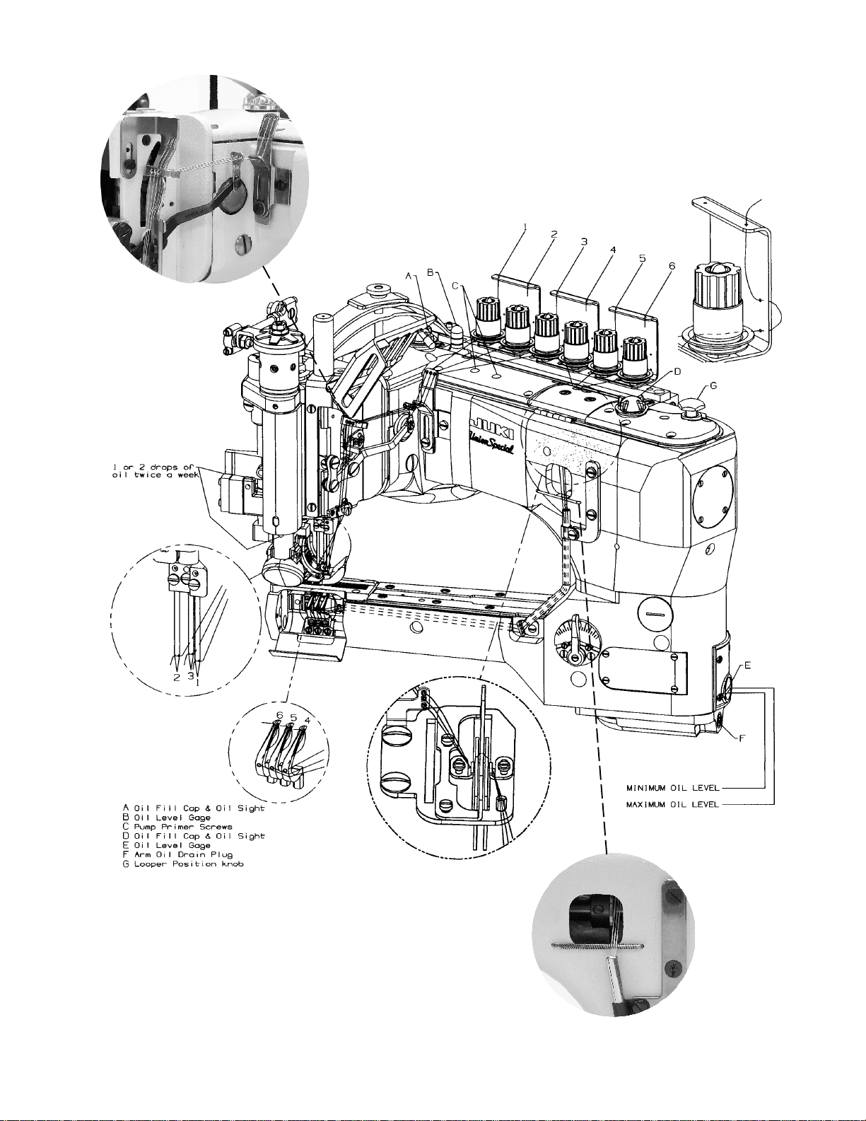
IDENTIFICATION OF MACHINES
Each UNION SPECIAL machine is identified by a style number, which is stamped into the style plate affixed to the middle of the
machine under the tension assembly.
The serial number is stamped in the casting at the right rear base of the machine.
CLASS DESCRIPTION
High Speed, Feed-Off-The-Arm High Throw Machines, Two and Three Needle, Left Needle In Front. Light Weight Presser Bar
Mechanism, Adjustable Looper Avoid, Space in Front of Needles 8" (203.2 mm), Double Disc Looper Thread Take-Up, Automatic
Enclosed Type Oiling System and Filter Type Oil Pump, Visual Sight Oil Action and Supply Gauges. Special soft stitch formation parts.
STYLE OF MACHINES
35800DNUB DOUBLE LAP SEAM. Three needle, high capacity, differential feed with upper driven roller feed. -Typical
Application- For in and out seaming on heavy weight denim garments. Seam Specification 401 LSc-
3. Standard gauge Numbers 8 [1/8", 3.2mm] and 9 [9/64", 3.6mm]. Recommended needle 130GS,
size 140/054. Maximum recommended speed 4500 R.P.M.. .094 step sewing parts. .468 (15/32,
11.9mm) narrow roller.
35800DNWB DOUBLE LAP SEAM. Three needle, high capacity, differential feed with upper driven roller feed. -Typical
Application- For in and out seaming on heavy weight denim garments. Seam Specification 401 LSc-
3. Standard gauge Numbers 8 [1/8", 3.2mm] and 9 [9/64", 3.6mm]. Recommended needle 130GS,
size 140/054. Maximum recommended speed 4500 R.P.M.. .094 step sewing parts. .588 (19/32,
15.0mm) wide roller.
35800DRUB DOUBLE LAP SEAM. Three needle, high capacity, plain feed, upper driven, roller feed. Feed Dogs have
higher teeth on front. - Typical Application- For seat seaming, in and out seams on medium to heavy
weight denim garments. Seam Specifications 401LSc-3. Standard gauge Numbers 8 [1/8", 3.2mm]
and 9 [9/64", 3.6mm]. Recommended needle 130GS, size 140/054. Maximum recommended speed
4500 R.P.M.. .094 step sewing parts. .468 (15/32", 11.9mm) narrow roller.
35800PZB Same as 35800DRUB except with reverse teeth roller.
35800DRWB DOUBLE LAP SEAM. Three needle, high capacity, plain feed, upper driven, roller feed (wide roller).
Feeds have higher teeth on front of feeds. - Typical Application- For seat seaming, in and out seams
on medium to heavy weight denim garments. Seam Specifications 401LSc-3. Standard gauge 9 [9/
64", 3.6mm]. Recommended needle 130GS, size 140/054. Maximum recommended speed 4500
R.P.M.. .094 step sewing parts. .588" (19/32", 15mm) wide roller.
selytSllA
SG031
3
6
mm2.7ro,mm6.3
devomereldeenretnechtiw
6.3~1.2
)dradnats2.3(
mm0.9
MPR0054
mumixam
3
Page 4

00853HCTITSNOOLLAB
DRADNATS
ETALPTAORHT
8ND428538UND008538BUND00853BEB084928DE428538DE
9ND428539UND008539BUND00853YDB084929CE428539CE
8XD428538BWND00853AEB084928ZD428538ZD
9XD428539BWND00853ZDB084929ZD428539ZD
8QD428538URD008538BURD00853CEB084928FE428538FE
9QD428539URD008539BURD00853DEB084929DE428539DE
8QD4285323ZP0085323BZP00853CEB084928FE428538FE
9QD4285363ZP0085363BZP00853DEB084929DE428539DE
DRADNATS
ELYTS
HCTITSNOOLLAB
ELYTSENIHCAM
TIFORTER
TIK
TAORHTWEN
ETALP
ET
ALPTAORHT
KRAM.D.I
9WQD428539WRD008539BWRD00853HEB084929FE428539FE
4
Page 5
5
Page 6
6
Page 7

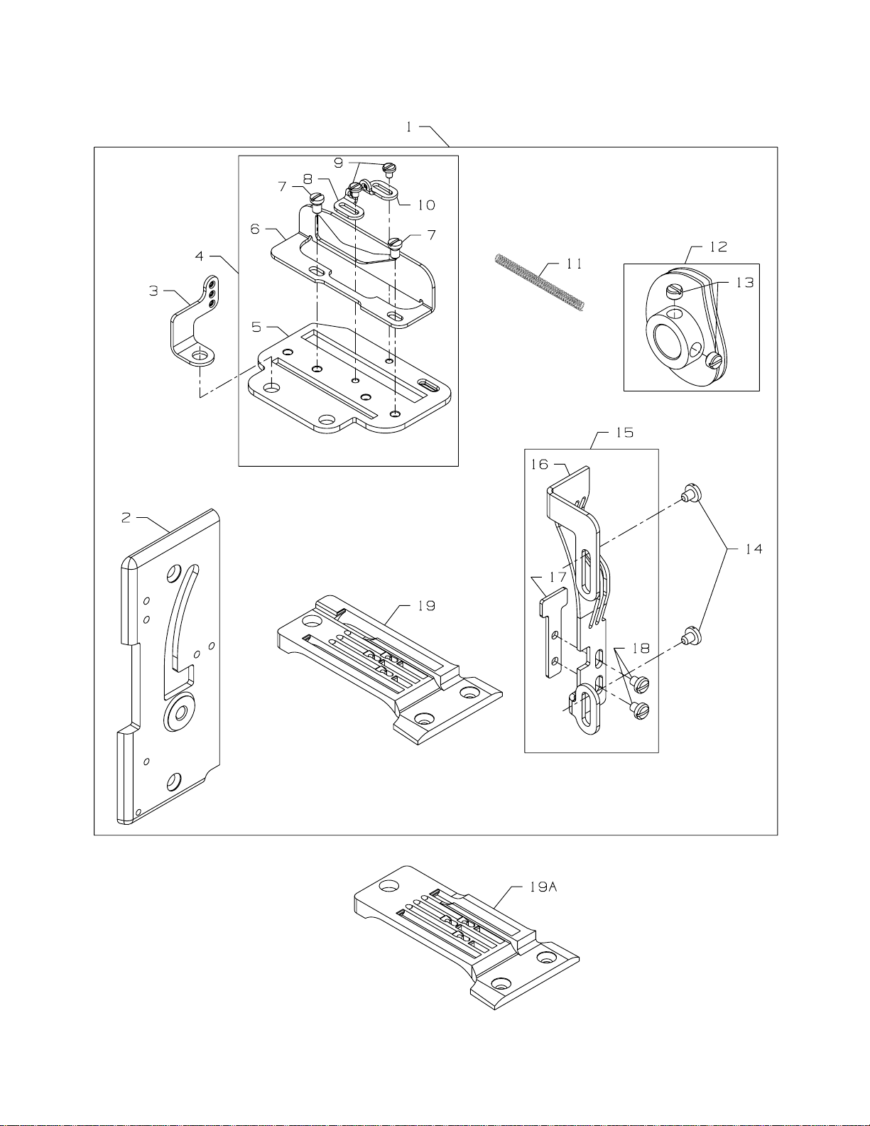
BALLOON STITCH PARTS
Ref.
No.
10.
11.
12.
13.
14.
15.
16.
17.
18.
19.
19A.
.
Part No.
1.
29480BEB
-
29480BDY
-
29480BEA
-
29480BDZ
-
29480BEC
-
29480BED
-
29480BEH
2.
35882K
3.
50658A
4.
29476CA
5.
35804B
6.
36204A
7.
22KH
8.
52958C
9.
73A
52958F
35853AN
35823D
22580
22704
29476CB
35804C
35804B
25B
35824DN8
-
35824DN9
-
35824DQ8
-
35824DQ9
35824DX8
-
35824DX9
-
35824DQW9
Description
Kit of Parts, for 35800DNUB8 .........................................................................
Kit of Parts, for 35800DNUB9 .........................................................................
Kit of Parts, for 35800DNWB8 ........................................................................
Kit of Parts, for 35800DNWB9 ........................................................................
Kit of Parts, for 35800DRUB8, 35800PZB32 .....................................................
Kit of Parts, for 35800DRUB9, 35800PZB36 .....................................................
Kit of Parts, for 35800DRWB9 ........................................................................
Front Cover ...........................................................................................
Looper Thread Eyelet ............................................................................
Cast-Off Plate Assembly .......................................................................
Cast-Off Plate .................................................................................
Cast-Off .........................................................................................
Screw .............................................................................................
Eyelet .............................................................................................
Screw .............................................................................................
Eyelet .............................................................................................
Looper Thread Spring ............................................................................
Double Disc Take-up Cam ....................................................................
Screw .............................................................................................
Screw ....................................................................................................
Needle Thread Take-up Assembly ........................................................
Needle Thread Take-up ..................................................................
Needle Thread Strike-off ................................................................
Screw .............................................................................................
Throat Plate, I. D. marked "ED8", for 29480BEB kit of parts ......................
Throat Plate, I. D. marked "EC9", for 29480BDY kit of parts .....................
Throat Plate, I. D. marked "EF8", for 29480BEC kit of parts .......................
Throat Plate, I. D. marked "ED9", for 29480BED kit of parts ......................
Throat Plate, I. D. marked "DZ8", for 29480BEA kit of parts ......................
Throat Plate, I. D. marked "DZ9", for 29480BDZ kit of parts ......................
Throat Plate, I. D. marked "EF9", for 29480BEH kit of parts .......................
Amt.
Req.
1
1
1
1
1
1
1
1
1
1
1
1
2
1
2
1
1
1
2
2
1
1
1
2
1
1
1
1
1
1
1
7
Page 8

Appearance of Standard vs. Soft
Double-locked Stitch
Standard Double-locked Stitch Soft Double-locked Stitch
NOTE:
THIS MANUAL IS USED FOR CHANGING THE
STANDARD PARTS TO SOFT DOUBLE-LOCKED
STITCH PARTS ON BOTH THE DIFFERENTIAL AND
PLAIN FEED 35800 MACHINES. THE STEPS ARE THE
SAME FOR BOTH MACHINE TYPES EXCEPT WHERE
NOTED.
8
Page 9

PROCEDURE FOR REMOVAL OF STANDARD STITCH PARTS
Step 1A. Remove screw for control lever
connecting link. Remove 2 screws
for front head cover, then remove
cover. Remove control lever
assembly and nipper plate
assembly.
Attach control lever assembly
and nipper plate assembly to
new cover supplied with kit.
Step 1A
Step 1B. Remove pressure regulating screw,
spring plate and upper and lower
leaf springs. Remove 9 screws for
chamber cover, then remove cover
and gasket. Remove 6 screws for
front top cover, then remove cover
and gasket. Remove 4 screws for
main frame end cover, then
remove cover and gasket.
Step 1B
9
Page 10

REMOVAL PROCEDURE, continued
Step 1C. Remove screw for plastic oil
reservoir, then remove reservoir.
Step 1C
Step 2
Step 3. Remove screw for stop shaft
washer, then remove washer.
Carefully slide looper drive
connection from end of
mainshaft.
Step 2. Remove 2 screws from cast off
plate, then remove plate. Loosen
but do not remove 2 screws for
take up cam.
10
Step 3
Page 11

NOTE: For differential feed machines, follow Steps 4A and 4B.
For plain feed machines, go to Step 5.
Step 4A. Loosen 2 cap screws for feed lift
eccentric assembly, and remove
top half of eccentric strap.
Note strap position when
removing—strap must be
reinstalled later in same
position to avoid binding.
Step 4A
Step 4B
Step 5. Loosen 2 screws in the double
feed eccentric assembly just
enough so eccentric will move
freely.
Step 4B. Loosen 2 screws in feed lift
eccentric and 2 screws in feed
drive eccentric just enough so that
eccentrics will turn freely on shaft.
11
Step 5
Page 12

REMOVAL PROCEDURE, continued
Step 6. Loosen 3 screws in mainshaft and
crankshaft coupling just enough
so that mainshaft will turn freely
inside of coupling.
Step 6
Step 7
Step 8. Lift presser foot and roller assembly ,
and remove standard throat plate.
Step 7. Pull mainshaft out from front of
machine only far enough so that
take up cam can be removed.
Remove take up cam.
12
Step 8
Page 13

PROCEDURE FOR INSTALLATION OF SOFT STITCH PARTS
Locate and identify new parts from kit.
Step 9. Install new throat plate and release
presser foot and roller assembly.
Step 9
Step 10
Step 11. Push mainshaft towards pulley
end of machine until timing spot
in the mainshaft aligns with spot
screw in coupling. T ighten spot
screw into spot of mainshaft and
then tighten remaining 2 screws.
Step 10. Locate new double disc take up
cam, and slide cam onto end of
mainshaft with collar side toward
the pulley end of the machine.
13
Step 11
Page 14

INSTALLATION PROCEDURE, continued
Note: For differential feed machines follow Steps 12A, 12B and 12C.
For plain feed machines follow Step 13.
Step 12A. Align spot screw in feed lift
eccentric with spot in mainshaft
and tighten spot screw, then
tighten remaining screw.
Step 12A
Step 12B
Step 12C. Locate top half of eccentric strap
which was removed previously.
Reassemble strap in same
position as it was prior to
removal, and tighten screws.
After assembly turn machine over
for several revolutions to make
certain machine does not bind. If
machine binds, check strap
position and repeat step 15.
Step 12B. Align spot screw in feed drive
eccentric with spot in mainshaft
and tighten spot screw, then tighten
remaining screw.
Step 12C
14
Page 15

Step 13. Align spot screw in double feed
eccentric assembly with spot in
mainshaft and tighten spot screw,
then tighten the remaining screw.
Step 13
Step 14
Step 15. A) Assemble new cast off plate
and eyelet from kit and tighten
with 2 screws.
B) Center double disc take up so
that cast-off plate is centered
between the take up discs.
Step 14. Reassemble looper drive to end of
mainshaft, replace washer and
tighten in place with screw.
15
Step 15
Page 16

INSTALLATION PROCEDURE, continued
Step 16. A.) Assemble new front head
cover and gasket to machine with
its 2 screws.
B) Attach connecting link to lever
with its screw.
Step 16
Step 17A. With needle bar at top of stroke,
position new needle thread take-up
so that notch in take-up fits over
needle thread eyelet.
Step 17A
16
Page 17

Step 17B. Rotate take-up clockwise, lower
it into position over control lever,
and attach to cover with its two
screws.
Step 17B
Step 18. Position new needle thread take-up
vertically so bottom of take-up
surface is even with top of cover
screw.
Thread machine so that one needle
thread passes through each hole
in needle lever thread eyelet.*
Needle thread strike-off
is set so it just touches needle
threads at bottom of needle stroke.
Step 18
*Same as standard threading.
17
Page 18

INSTALLATION PROCEDURE, continued
Step 19A. Reassemble plastic oil reservoir
with its screw.
Step 19A
Step 19B
Step 19C. Remove Looper thread guide
wire and slide spring from kit
over the wire and then replace
guide wire on machine.
Step 19B. Reassemble chamber cover, top
cover, main frame end cover and
presser foot tension springs.
18
Step 19C
Page 19

Step 20
Step 20 Set both looper thread pull-off
eyelets maximum to the right.
Set double disc take-up cam so that
looper thread casts off from high
point of cam when tips of
the needles on down stroke are
between bottom of throat plate
and top of loopers.
Thread one looper thread through
each hole in new eyelet from kit.
Step 21 Set needle thread tensions to
high, so that needle threads are
pulled up very tight against
material. Set looper thread
tensions to low, so that maximum
amount of looper thread is in the
material.
Step 21
19
Page 20

 Loading...