

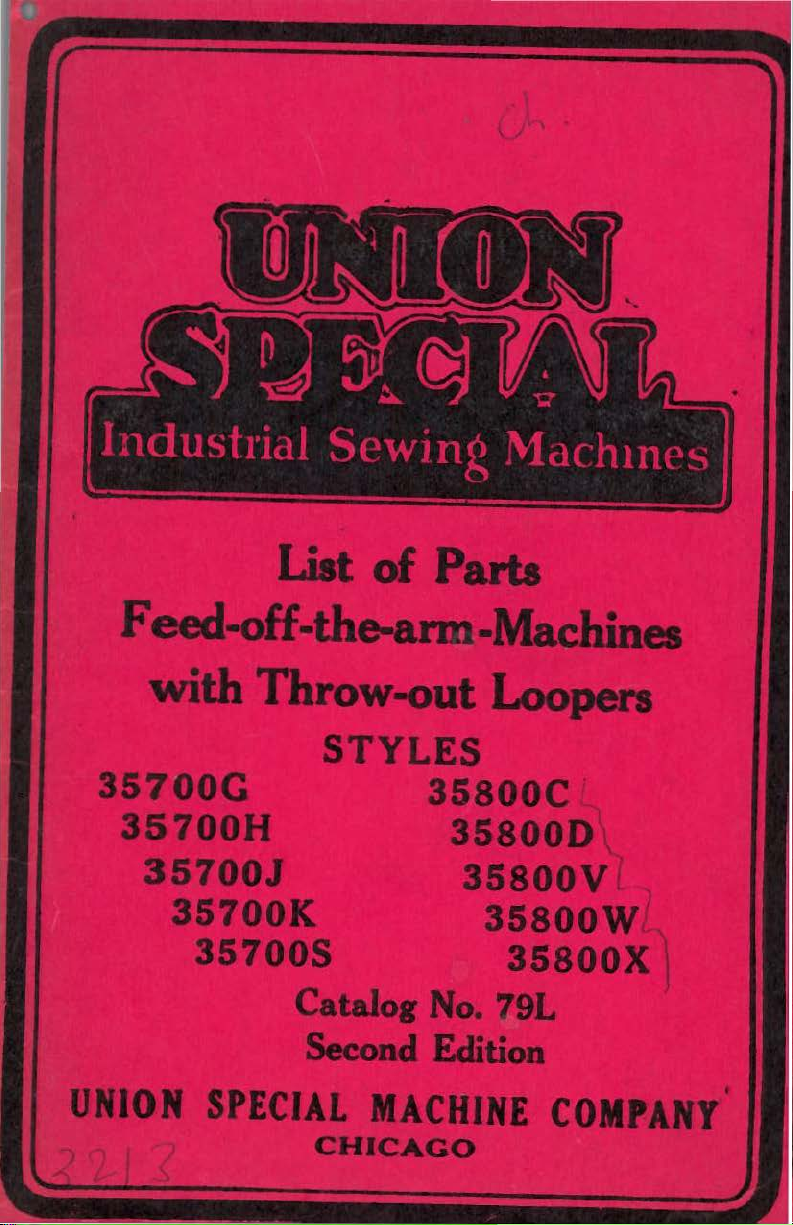
Page 1
Page 2
Cat alog No. 79 L
LIST
OF
PARTS
The pa
furn
i shed a t l i
Feed-off-the-arm
wi
th
Throw-out
Styles
35700 G
35700 H
35
700 J
3570 0 K
35
700 s
rts
l i st ed
in
st pric
Se
cond Editio
Ma
Loopers
3
5800
35
35
t h
is
es
for
n
chines
c
800 D
80
0 v
35800 w
35800 X
cat al og a
r epa i
rs
re
only
Co
pyr i g
ht
1940
By
Union Speci al Machine Co.
Righ
t s
Reser
ved
In
Al l
Countries
Un
i on S
pecia
C
hicago U.
Pr
int
l Ma chi ne Co
S.A.
ed in
U.S.
A.
mpa
ny
Page 3
OFFICES,
FOREIGN
SERVICE
STATIONS,
DISTRIBUTORS
*CHICAGO,
Co.,
Factory. T.
W. Mcl:ain, Asst. Gen. Sales Mgr.
Morris, Foreign
District
ALLENTOWN, PA. 1749 Turner St.
P.
0.
2·9474.
*ATLANTA, GA. I H Spring St. P. T.
McLendon, Mg
BALTIMORE, MD.
A.
McGwier.
*BOSTON,
Stevens, Mgr.
*CINCINNATI,
W.
E.
CLEVELAND,
D.
Bear
DETROIT, MICH. 2725 Boston Blvd. W.
J. F. Li
FT.
WORTH,
Drive. H. M. Petershagen.
GREENSBORO, N.
hall
St. L. F. McGwier.
GREENVILLE,
0.
S.
JOHNSON CITY, N.
Wm . Browne.
KANSAS CITY, MO. 5014
T.
0 .
LOS ANGELES, CAL.
St.
C.
MIAMI, FLA. 35 N.
McDonald.
MINNEAPOLIS,
So., R. W. Bredahl.
MONTREAL, QUE.
Prince Arthur. S. J. Storey,
LA 7944.
NASHVILLE, TENN. Observatory Drive.
J.
W.
NEW
ARK, N.
ning.
NEW
Bldg.
8137.
*NEW
Wm. Bleicher, Mgr.
4·4665 or 4·4666.
*PHILADELPHIA,
T.
M.
nut
3131, (Key .) Race 1078.
PITTSBURGH, PA. 3217 Pinehurst Ave.
R.
G.
PORTLAND, ORE. 2525 N.
St.
R.
POTTSVILLE, PA.
L.
J. Perrin.
*ST
. LOUIS, MO. 1127 Pine St.
Gratsch, Mgr. 'Td. Main 1776.
ILL. Union
404 N. Franklin St. Main
S. Whits
Sale
Sale
s Mgr.
Box
12B.
r.
'Tel.
MASS. 210 South
'Tel.
Special
el,
Gen.
s Mgr.
A.
'Tel.
Superior 6920.
W.
L.
Johnson, 'Td.
'Tel
. Main 3377.
34
S.
Pla
Eutaw St. H.
za 8499.
Liberty 0146 .
Machine
Office
Sales Mgr.
L.
E.
Brauch,
St.
C. E.
and
0 . 422 Temple Bar Bldg.
LeRoy, Mg
. 'Td. Main
vingston.
Bachelor.
Biggers.
E.
Downs.
Brauch. 'Td. 8·5'123.
'Tel
.
Mar~et
ORLEANS, LA. 202 Godchaux
M.
YORK, N.
Murphey, Mgr.
Timm. 'Td. Locust 1086.
M.
Seay.
r.
'Tel.
0.
'Tel. 'Tyler 6·4118.
TEX. 912 Morningsi
S.
'Tel.
'Tel.
'Tel. Wabash 6966.
MINN
J.
60 Park Place. H. K. Lan·
0 . Moulton.
'Tel.
'Tel.
2508·].
Par~way
1276 W. Third St. K.
965'7.
'Tel
C.
402 S. Menden·
'Tel.
C. 601 Cleveland St.
7·3179.
'Tel
3·3123.
PA.
20
6301
5'404W.
Y.
49 Cherry St.
College Ave.
1303
. Prospect 5636.
E.
First St.
. 3608 27th Ave.
'T
d . Drexel 3 3 3
Blvd
. St. Laurent at
'Tel
. Raymond
Y.
116
E.
'Tel.
Murray Hill
401
N. Broad St.
'Tel
. (Bell)
Lancaster 4794.
South Center
25'21.
. 4·7776 .
.
So.
Main
J.
I.
'Tel.
27th St.
Wal·
E.
Glisan
E. E.
W.
St.
*SAN
J.
*TORONTO,
C.
UTICA,
WATERFORD, N. Y.
WINNIPEG, MAN. 1065 Domini
YORK, PA. 837 Florida Ave. Wm. Den·
de
FRANCISCO, CAL.
Ben
W. Merz, Mg
W. G. 1\. Rundle, Mgr.
2909.
N.
'Tel
Brown. 'Tel. 467.
Walter Baldwi
holm. 'Tel.
Y.
. 4·6422.
ONT. 137
33
n.
64196.
r.
Leslie
'Tel.
'Tel
St.
22
24244.
. Garfield 7999.
Wellington St.
'Tel.
P.
Fourth St. A.
OVERSEAS
AFRICA-C~etown,
burg, Port Elizabeth,
Louis,
Mauriti
ASIA- Hong
tsi
n,
Tokyo, Japan. Manila,
ASIA
rut, Syria. Baghdad, Iraq. Teheran, Iran.
AUSTRALIA -
Perth, Sydney.
EUROPE
ha
gen, Denma
Manchester, England. Hels
land. Paris and
Vienna, Chemnitz, Ebin
Frankfurt
Germany. Milan, Italy.
Oporto, Portug
Scotland. Barcelona, Spai
holm and Orebro, Sweden. Zurich,
Switz
NEW ZEALAND - Auckland, Christ·
church, Dunedin, Wellington.
NORTH
Mexico City and Monterrey, Mexico. Ja·
maic
a,
PACIFIC ISLANDS-Honolulu, Hawaii.
SOUTH AMERICA-Buenos Aires, Ar·
gentina. Porto Aleg
cife, Brazil. Santiago,
Bo
gota, Medellin, Colombia. Guayaquil,
Ecuador.
gu
ay.
Kon
China. Calcutta, India. Osaka and
MINOR
- Tel Av
- Brussels,
am
erland.
AMERICA - Havana, Cuba.
B.
W. I. San Juan, P.
Lima,
Caracas, Venezuela.
Durba
n,
So'uth
us.
Cairo, Egypt.
g, Shang
Bri
rk.
Leice
Lyon
Main,
al.
Dundee a
Peru. Montevideo, Uru ·
Africa. Port
hai
P. I.
iv,
Palestine.
sbane, Melbourne,
Belgium.
ster, London and
in
s,
France. Berlin,
ge
Kol
n, Stuttgart,
Os
lo,
nd Glasg
n.
Boras,
re,
Sao
Chil
e.
Barranquilla,
371
4th St.
Adelai
de
J. Steeper.
on
St.
Johannes·
, and Tien·
Bei
Copen·
gfor
s,
Fin·
n,
Erfurt,
Norway.
ow,
Stock·
R.
Paulo, Re·
J.
·
*MAIN
OFFICES
Page 4
0
Each
in
fied
one
"Z".
letter 11Z
a
standard
Union
the
name
as
standard
or
more
Example: 1135700 G
11
standard
are
machine a 11Z
style
Styles
of
under a class
that
it
contains
This
as
Light
of
ordinary
catalog
listed
It
machines
-the-arm
Duty
G
For
ines
loopers.
special
Feed-off
35700
underwear,
two
loopers,
tween ne
edles
tractor
8,
10,
and
IDENTIFICATION
Special
plate
letters
special.
on
and
suffixed,
carries
the
machine.
special.
11
•
\\1hen
11
is
a
but
Style
only
merely
number. Example: 1135700
machines
number
no
similar
¥'hich
letters.
in
differs
Example: 1135700
APPLICATION
applies
herein,
can
also
in
STYLES
Machines,
\\ork,
double
quality
pajamas and
right
in
f eed
,Type
only
which
be
applied
Classes
OF
MACHINES
Double
stitch
shirts, \''ai s
simil
needle
line
with fee
107 G
to
are
35700 and
~
:-i
th
Locked
felling the
ar ga
in
needles, standa r d gau
12.
OF
MACHINES
style
Those which
number which
Style
never
contain
numbers
minor
suffixed
GZ
numbers
are
containing the
changes
11
construction
from
the
OF
CATALOG
the
standard
equipped v·ith
with
discretion
35800.
IN
CLASS
Throw-out
Stitch
35700
Loop
Type 401
tubul
ts, shorts, athle
rment
front,
d, sea
s ; two n
5/ 32
inch
m Type LSc-2,
standard
to
the
•
are
style
11
•
styles
throv•-out
rs,
ar por t
is stamped
are
classi-
the
letter
are made
respective
grouped
number
of mach-
to
the
for
ions
t i c
eedle
s,
spa
ce
be-
ges
Nos
have
i n
in
.
35700 H
extra
lingerie
right
in
107 G
35700 J Same
tumbler
shirts,
35700 K Same
tumbler
quality
35700 S
of
three
between
tractor
For
fine
needle
line
needles,
For
shirts,
loopers,
double
stitch
quality
and
similar garments;
in
with
front,
feed,
standard gauges
as
foot
standar
foot,
shirts,
35700
and
is
d ga
as
35700
and
is
standard gauges
triple
stitch
pajamas and
right
needles
feed,
in
Type 128
shirts,
5/
waists,
....
2 i n
seam Type L
fellin
G,
except
designed
uges
Nos.
H,
exce
pt
designed
felling the
simil
needle
line
ar g
in
with feed,
GC
needles, sta
- 3 -
g t
he
tubul
shorts,
two need
ch
spa
Sc-
2, tra
ce
ar p
pajamas
les,
two ooper s ,
bet ween n
ctor
f eed, Ty
Nos. a, 10, and 12.
it
has plain feed
for fell
8,
it
for
ing ordinary qual
10
and 12.
has
plain feed v;i
felling extr
Nos.
8,
10 and 12
tubular
arments;
front,
sea
three needles,
-5/ 32
inch spa
m Type LSc-3,
ndard gau
orti
ons
,
eedle
wit
a f
ine
portions
ce
ge No.
th
of
s
pe
h
ity
1
6.
)'
·1
\
Page 5
STYL
ES
Of
MACHINES
IN
CLASS
~
5700
(Cont'd)
35700 Z A
Cla
ss 35700,
Feed-Off-Th
spec
but
e-Arm
i a1
style,
differin
STYLES
~achines,
OF
Heavy Duty Work, Double Locked
For
35800 C
overalls,
non-sanfori
needle
with
needles,
35800 D
trousers
weight
needle
with
needles,
35800 V
overalls,
2.00
needles,
space
tractor
Nos. 8 and
35800 W
lar
materials;
of
feed
pendicular
double sti
trousers,
zed materi
in
front, 3/16
feed,
seam Type
standar
For
double
made fr6m
trouser f<i
in
f
feed,
ront,~3/16
seam Type
standard gauges
For
triple
trouser&,
to
4.00
yard
three
between
feed,
loopers, rig
needles
Type 128
9.
For
use
on
tractbr
dog
in
line
with
tch
coats
als;
inch spa
LSc-2,
tl
gaug
es
stitch
seersucker,
brics,
inch
LSc-2,
stitch
coats
non-sanforized
in
2.00
to
feed,
~ith
line
of
similar
g
in
some
MACHIN
ES
With
Thro~-out
felling the
and
similar
t?.
·o
needles,
ce
plain
Nos. 16 and
felling the
khaki
t wo
needles,
space
tractor
Nos. 12 and
felling the
and
similar
ht
needle
line
GC
with
needles,
2.40
yard
rith
feed
feed,
and
otherwise
to
the
standard
of
its
component pa
IN CLASS
35800
Loopers,
Stitch
Type 401
tubular
garments
two
betv•een
feed,
needles
Type 128
18.
tubular
and
similar lig
h ·o
feed,
loopers,
needles
Type 128
between
16.
tubular
garments
materials;
in
front,
feed,
seam Type
standard gauges
Sanforized
step-up
step-up
on r ig
in front
same
styles
portions
made
loopers,
portions
portions
made
three
3/16
and s
ht
as
35800
For
in
GC
right
in
GC
LSc-3,
side
per-
in
rts.
of
from
right
line
of
ht
line
of
from
inch
imi-
V.
35800 X
terials;
dog
35800 Z A
in
For
use
tractor
in
line
with
special
Class 35800,
on 2
feed,
feed,
style,
but
.00
to
2.40
with ste
yard
p-up
otherwise same as
simil
differin
ar
g
in
non-Sanforized maon right side
35800 V.
to
the
me
st anda
of
its
so
of
rd
styl
es
component
fee
parts.
NEEDLES
TY
PE
NUMBE
RS
AND
E
ach
denotes
and
other
of
the
tween
shank.
the
complete
needle
the
details.
blade, mea
the
shank
Collectively,
has a ty
kind
and e
symbol.
SIZES
pe number and
of shank,
The
sured
latter
in
ye,
the
point,
denotes
thousandths
and
is
type
stamped
number and s i ze number
-4-
size
number. The former
length, groove, finish,
the lar ges t di
of
an inch
in
the
needle
ameter
midway
is
be-
d
Page 6
To
have
package, a sample
should
order
03
6".
in
the
listed
cription
orders
be g
would
The
styles
below.
of
iven.
read
type
of
Set
the
NE
EDLES
promptly
needle,
See marks
as
follows
numbers
machines
opposite
needle.
and
or
of
the
covered
(Cont'd)
accurately
the
type
on
packages.
"1000
needles
each
type
and
Needles
available
by
this
number
f i l
led,
size
An
Type 107 G
catalog
the
number
intelligent
for
is
the
empty
Size
use
are
des-
Type No.
104
J
104
JC
107
107 G
lOB
C
lOB
GC
lOB
HA
128
c
Round
groove,
standard,
the
Same
size
Round
groove,
than
032, 036,
Same
032,
Round
g
less
040,
Same as
sizes 036,
Same
plated-
Round
ball
than
size
040, 044,
size
as
032
standard,
as
036,
roove,
than
044
as
eye,
standard,
one
shank,
spotted,
Type
shank,
ball
Type
shank,
ball eye,
Type
Type
sizes
shank,
Description
round
taper
number,
104
round
eye,
040,
107,
040,
round
standard,
108
040,
lOB
040,
round
spotted,
step
width
reduction,
049
point,
short
blade, diameter
chromium
J,
except
point,
short
nickel
044
except
044
point,
spotte
nickel
c,
except
044
C,
except
044
point,
short
blade
plated-
d,
of
eye
extra
plated-
chromium
extra
blade
chromium
extra
short
plated-
chromium
ball
short,
blade
nickel
short,
1/8
inch
across
si
short,
1/8
inch
sizes
plated-
short,
blade
sizes
point,
double
1/8
and groov
inch les
plated-
double
less
eye
zes
029, 032
plated-
double
less
027,
double
1/8
plated-
chromium
groove,
es
under-
size
than
is
029,
sizes
inch
036,
s
s
12B H
GC
128
128
GH
Same
as
036, 040, 044,
Same
sizes
Sa
me
plated-
Type 12B c,
as
Type 128 c,
040,
044, 049
as
Type 128
sizes 036,
049
C,
040, 044,
- 5-
except
except
except
ball
poi
nt-
chromium plat e
bal l poi
049
nt,
sizes
d-
chromium
Page 7
NE
EDLES
(Cont'd)
APPLICATION
The
standard
listed
machines
opposite
needles
numerically,
machine
in
the
covered
the
that
makes
OF
TYPE NUMBERS
type
of
description
by
style
can
as
it
this
numbers
be
used.
the
variety
impractical
needle
of
catalog are
Machine
Style
35700G
35700H
35700J
35700K
35700S
35800C
358000
104J,
104J,
104J,
l04J,
104J,
l28C,
l28C,
l04JC,
104JC,
l04JC,
l04JC,
l04JC,
128H, 128GC,
128H, 128GC,
Type
107,
107,
107,
107,
107,
35800V 128C, 128H, 128GC,
35800W
35800X
l28C,
l28C,
128H, 128GC,
l28H,
128GC,
ORDERING
PLATES
Grouped,
of
parts
nent
parts
according to
similar
that
in
go
scale,
appearance,
in
the
same
ism.
~~en
a g
iven
desi
gn
of
or
sizes,
only
ordering these
information
be
one illustration
pieces,
furnished
it
part
is
as
tions.
TO
MACHINES
applicable
each
style.
listed
are
the
type
Type numbers
of
the
to
of
l07G,
l07G,
107G,
107G,
107G,
materials
show a
Needles
l08C,
lOBC,
108C,
lOBC,
108C,
128GH
128GH
128GH
128GH
128GH
REPAIR
will
and,
PARTS
be
to
subdivision
is
made
is
usually
necessary
requested
to
each
The
styles
herev•ith.
numbers
are
arranged
sewed on
preference.
108GC,
l08GC,
lOSGC,
l08GC, l08HA
l08GC, l08HA
found
in
that
under
some
of
two
shov~.
the
these
illustrations
extent,
the
or
style
of
of
the
lOSHA
l08HA
108HA
compo-
mechan-
more g
In
additional
illustra-
is
Set
each
au
es
LIST
OF
Turnin
cription
found.
before
plate
\\'hen a part
covered
the
For
nuts,
PARTS
g from
of
each
Alvr
ays
ordering.
number.
by
this
description.
convenience
and
similar
the
part
check
is
used,
catalog,
plates
and
the
It
is
or
in
orderin
articles
to
its
symbol
not
can
no
are
the
list
principal
against
necessary
be
used,
specific
g, !IIinor
repeated
of
uses v·ill
its
to
in
use
parts
after
parts,
description
furnish
all
machines
is
mentioned
such
each
the
the
as
des-
be
scr
major
in
ev·
s,
part.
(-) A dash
parts
indicates
in
the
the
"plate
absence
number" column
of
an
illustration.
-6
-
of
the
list
of
Page 8
LIST
OF
(*)
indicates
separately.
impossible
time
PARTS
A
double
and make a
ORDERING
(Cont1d)
dagg
that
the
Due
for
to
these associated
serviceable
REPAIR
er
in
component
the
the high
PARTS
"symbol
parts
speed
parts
job.
(Cont'd)
to
cannot
of
these
to
order
be
be
by" column
furnished
machines
fitt
ed a
it
is
second
IDENTIFYING
W
here
its
ith
w
parts
All
the
SUPPLIES
All
hooks,
and
USE
Success
only
Parts
its
it
Speci
are
pr
inci
ximum eff
ma
Genuine
"Trade
stamped
with a link
symbolic
parts
TERMS
Prices
v•
ithout
risk
sured
cover
the
part
number.
an
identification
similar
part
catalog
supplies,
belt
pov•dered
GENUINE
by
the
as
furnished
subsidiaries
is
to
our
als
by
desi
gned
ples,
'UNION
with a reproduction
of
are
are
notice. All
f.o.b.
unless otherwise di
the
PARTS
construction
numbers
in
fasteners,
NEEDLES
in
use
furnishing the
and
iciency
needl
connecting the shackl
superlativ
bog
shippin
posta
Some
in
appearance.
represent
which
including taps,
oil
stone
the
operation
of genuine
by
and
interest
according to
are made v·ith
and
es a
re
SPECIAL'
us.
strictly "net
g poi n
ge and i
permi
of
the
letter
they
appear.
belt
will
AND REPAIR
Union Spe
the
Union
authorized
to
maintain
very
the
durability are
put
up
mark".
e e
xcellence.
shi
cash"
pments a
t.
rected.
nsurance.
ts, each
smaller parts
to distinguish
the
same
reamers,
punches,
be
promptly
PARTS
of
these machines
most
the utm
in packages
of
Parcel p
cial
Spec i
al
distributors.
the
best
goods
approved sci enti f
ost
Genuine
the
well
es.
All
and
subject
re forwarded
ost
A
charge
part
is
stamped
are
stamped
them from
part,
scr
reput
assured.
Both trade ma
regardless
beltin
ew
furnished.
Needl
Machine
precis
marked
repair parts are
knovrn two padlocks
other
shipments
g, be
drivers,
can
be secured
es and Re
Company,
Obviously,
at i on
obtainable.
i s m
of
i on . The
at
needles
to chan e
t the buye
ade
with
of
lt
v-renches
pair
Union
They
ic
t he
top
rks are
and
r's
are
in-
to
-
7-
Page 9
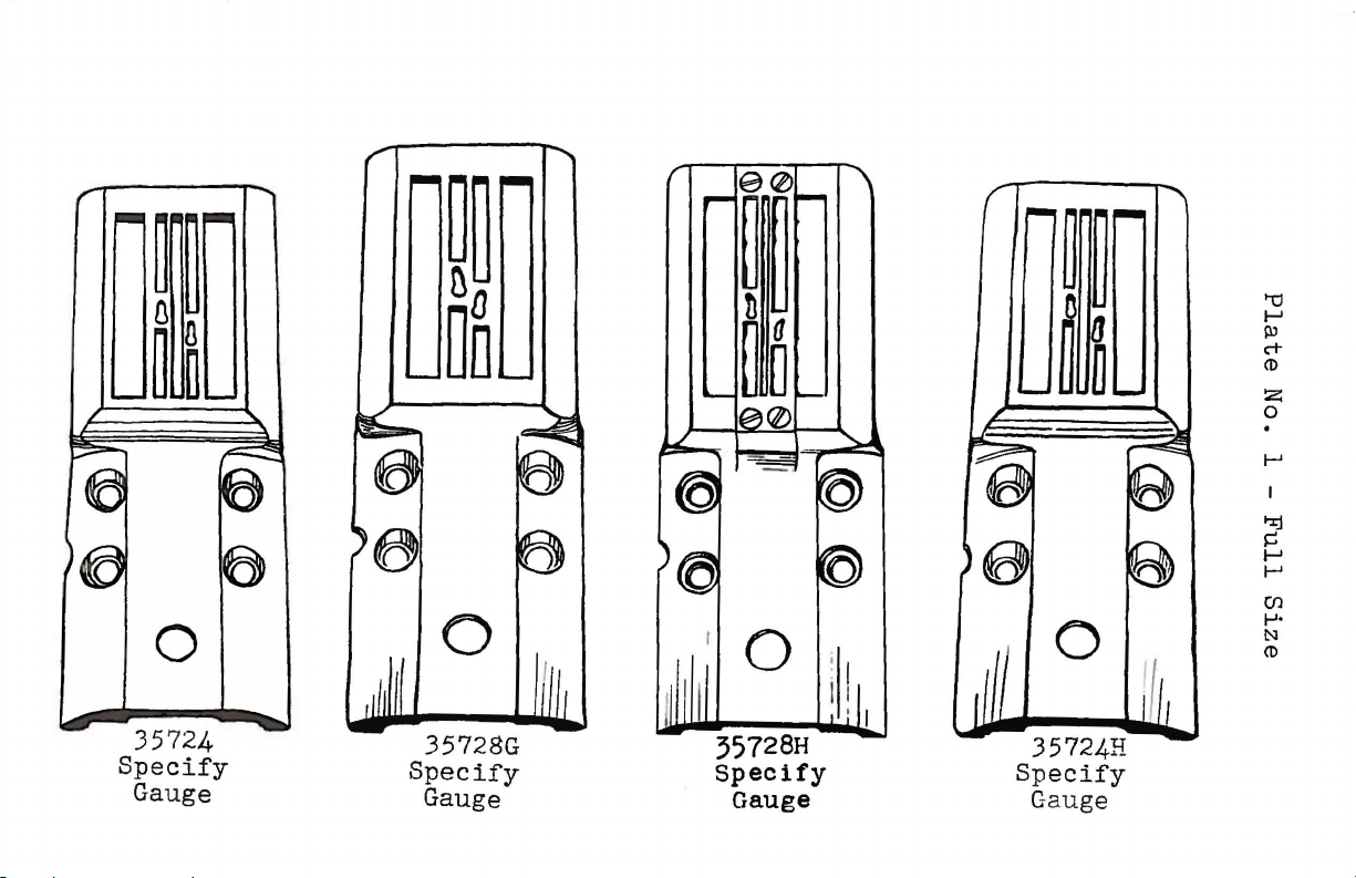
16)
0
357
24
Specify
Ga
uge
35728G
Specify
Gauge
0
35724H
Speci
Gauge
fy
I
I
t-el
I-'
PJ
c+
<D
!2:
0
.
I-'
I
"%j
~
I-'
I-'
(/)
1-'·
N
<D
Page 10
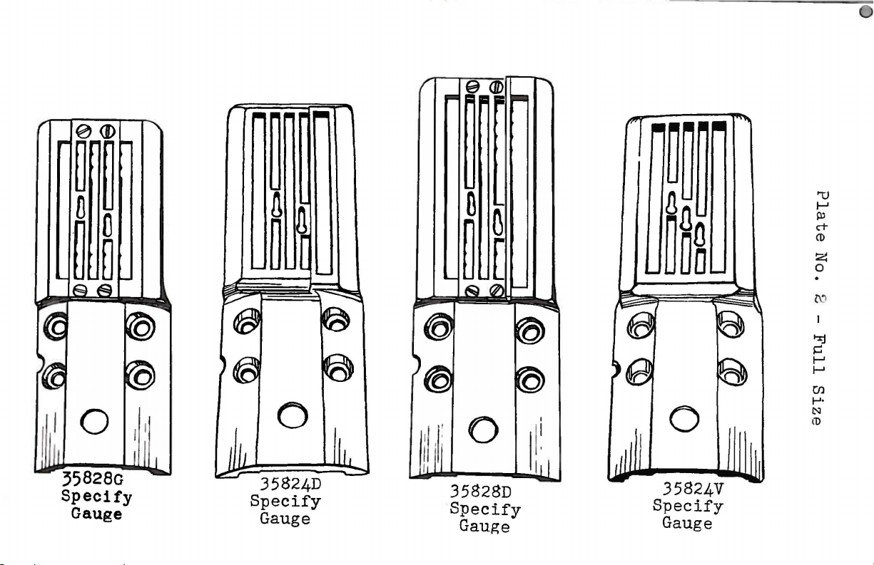
~~
~
D
35828D
Specify
Gauge
"U
I-'
Ill
c-t-
CD
z
0
.
1:\,
1-:j
~
I-'
I-'
rn
1-'·
1:\1
i
l>
l
!i
Page 11
·
·o
0
0
..
,
'1:1
1--'
Pl
c+
(l)
z
0
.
(J-1
"%j
s=
1--'
1--'
(/)
1-'·
N
(l)
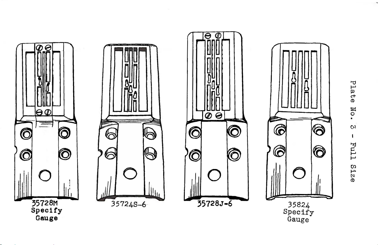
35728M
Specify
Gauge
35824
Specify
Gauge
Page 12
'"tl
1-'
PJ
("t-
eD
z
0
.
~
"%.!
J,::
1-'
1-'
(f)
.....
1:'1
CD
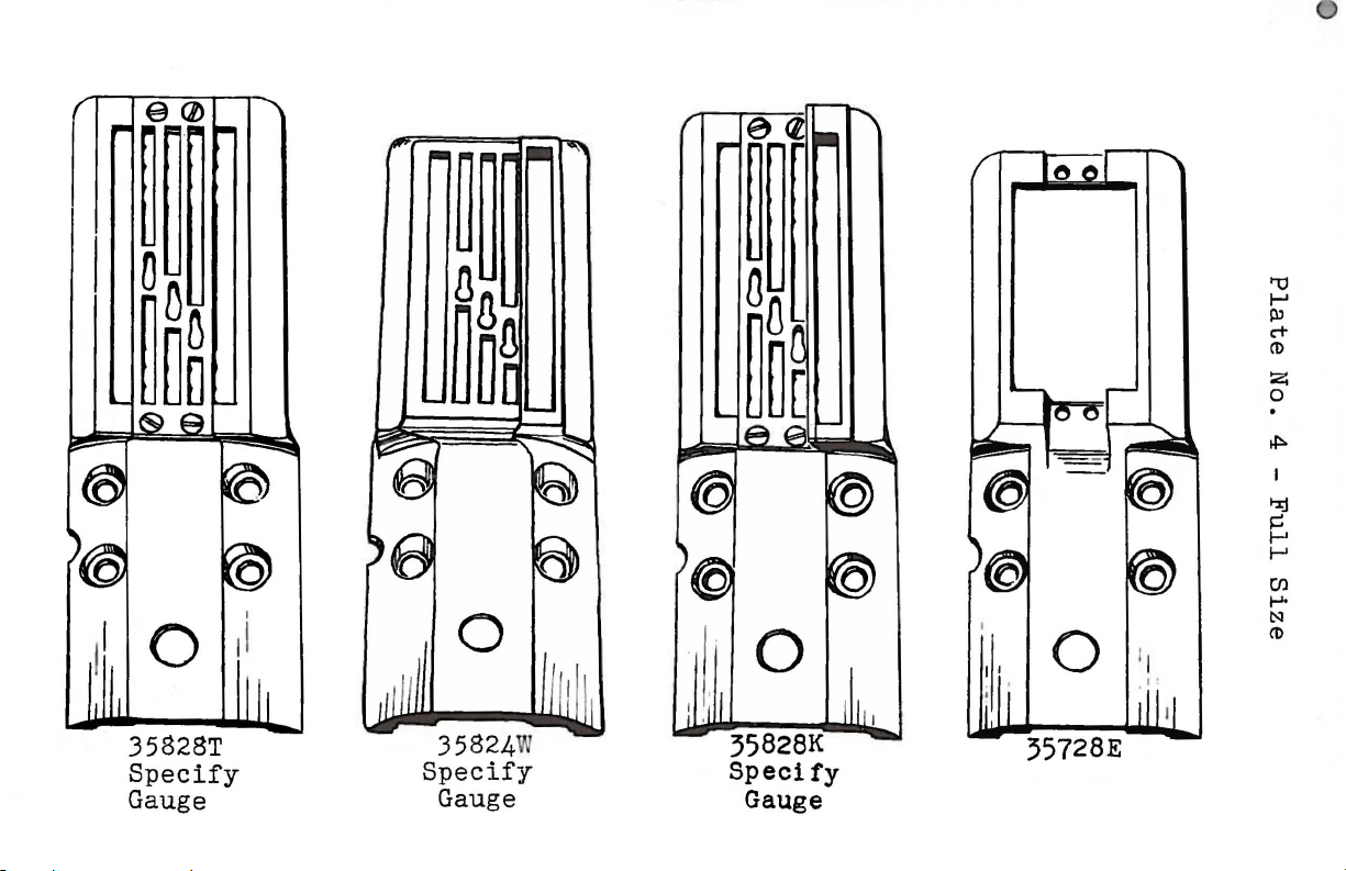
35828T
Specify
Gauge
35728E
Page 13
Plate
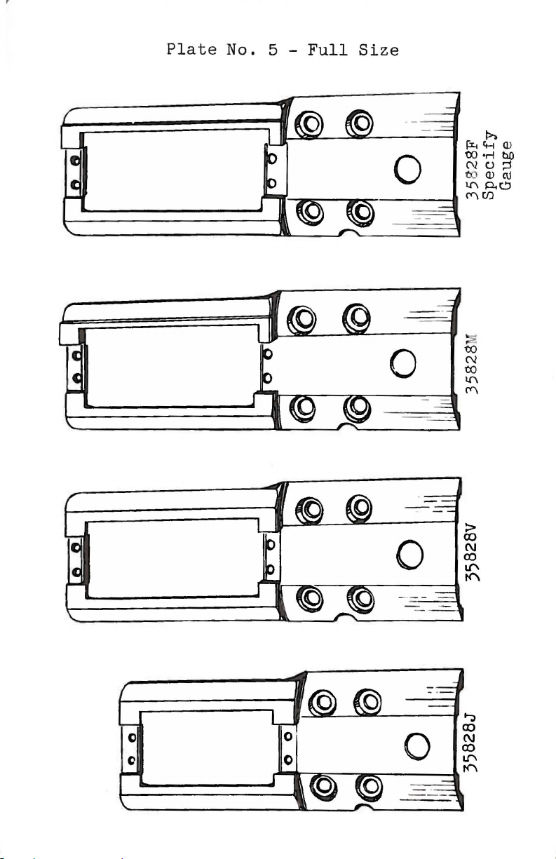
No. 5 -
,...,,_,....,..._..,.,..~-----1
Full
Size
rx..
Ci-t
00
•r-l
N0::1
OJ
l.l'\
C'\
(J)
1>.
Q)(\j
p.~
(!)
bO
Page 14
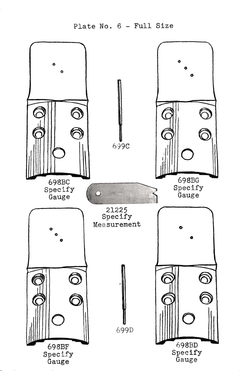
Plate
No. 6 -
Full
Size
0
698BC
Speci
Gauge
0
0
0
0
e
fy
61
9C
21225
Specify
Measurement
0
0
0
0
0
0
0
0
699D
698BF
Specify
Gauge
698BD
Spe
cify
Gauge
Page 15
35728N
Specify
Gau
ge
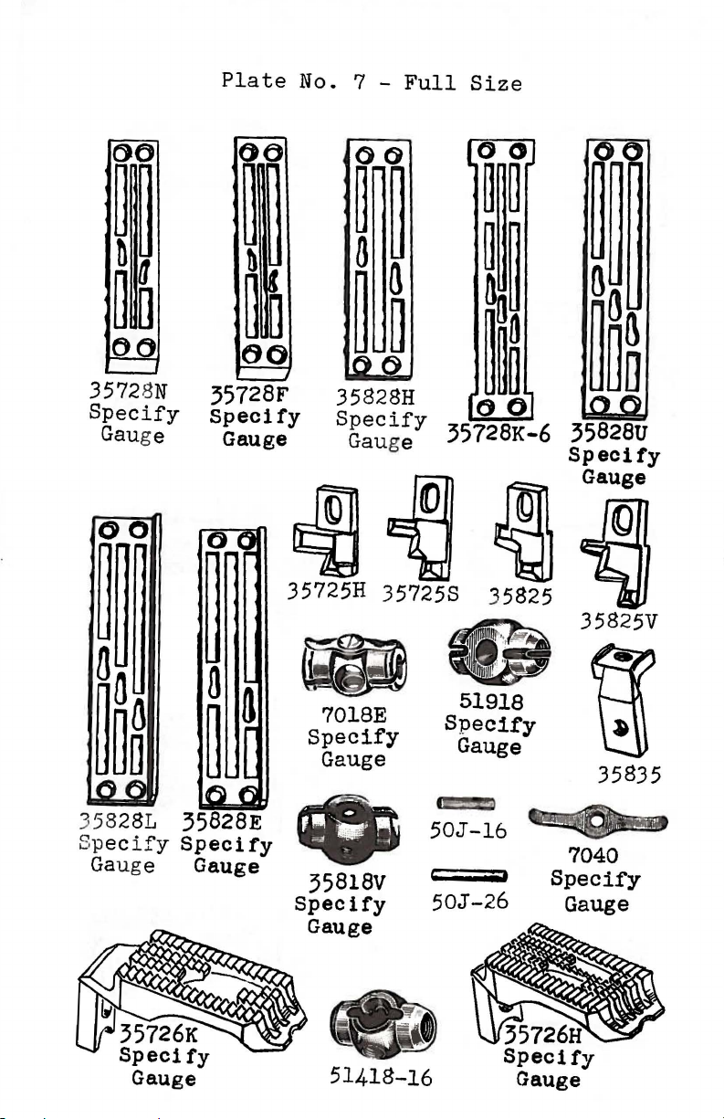
Plate
No. 7 -
Full
Size
35835
•
35818V
Spec 1
fy
Gauge
51418-16
•
50J-16
50J
-26
7040
Specif'y
Gauge
Specify
Gauge
Page 16
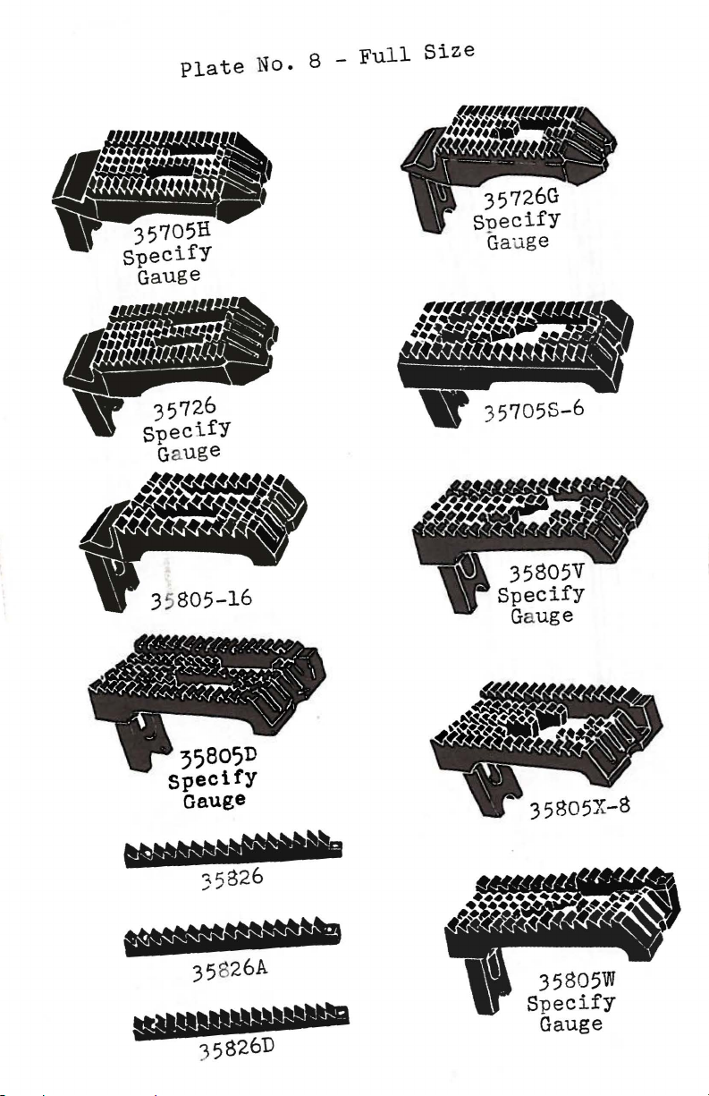
Plate
No. 8 -
Full
Size
35826A
35805W
Specify
Gauge
Page 17
r
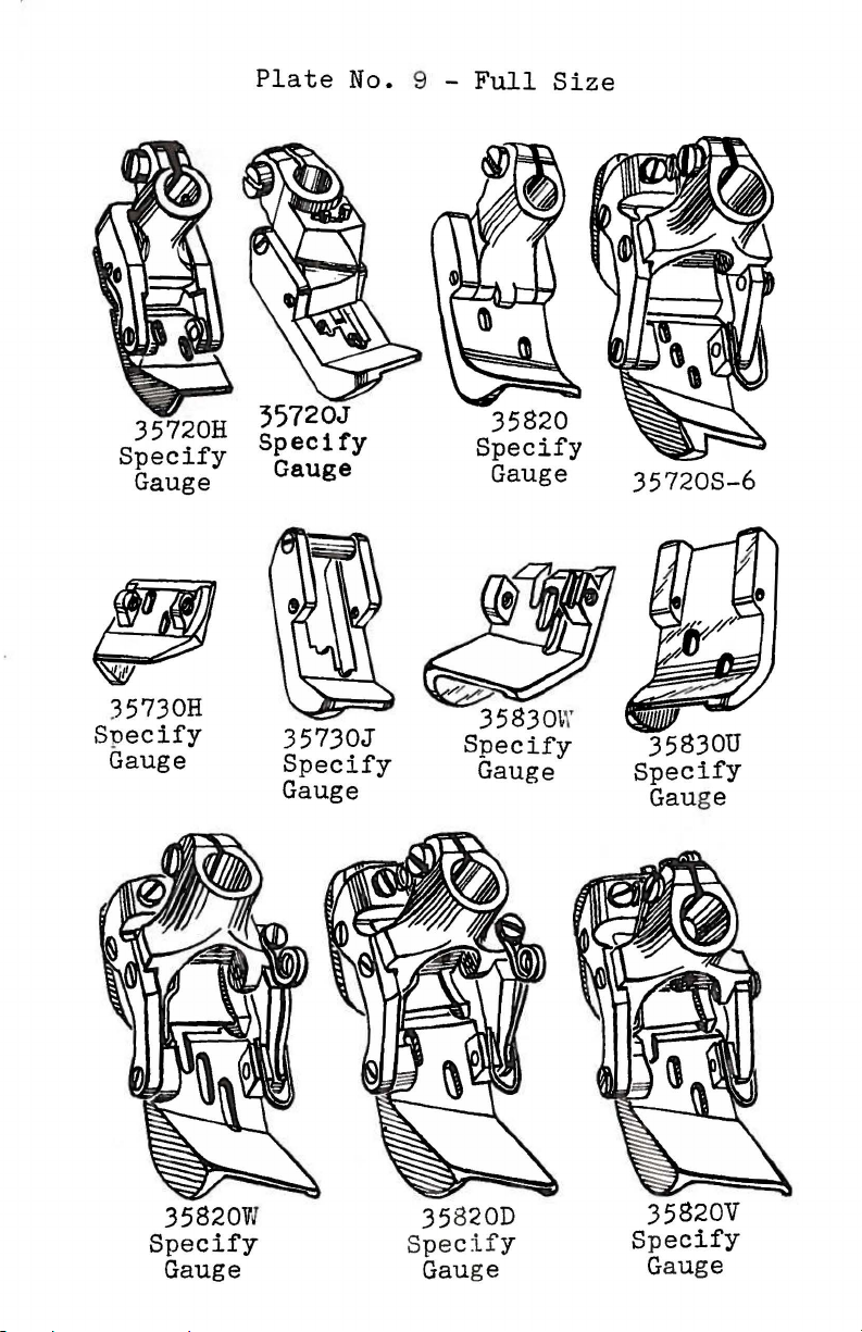
35730H
Specify
Gauge
Plate
35720J
Specify
Gauge
35730J
Specify
Gauge
No. 9 -
Full
Size
35820
Specify
Gauge
35720S-6
35830U
Specify
Gauge
35820W
Specify
Gauge
35820D
Specify
Gauge
35820V
Sp
ecify
Gauge
Page 18
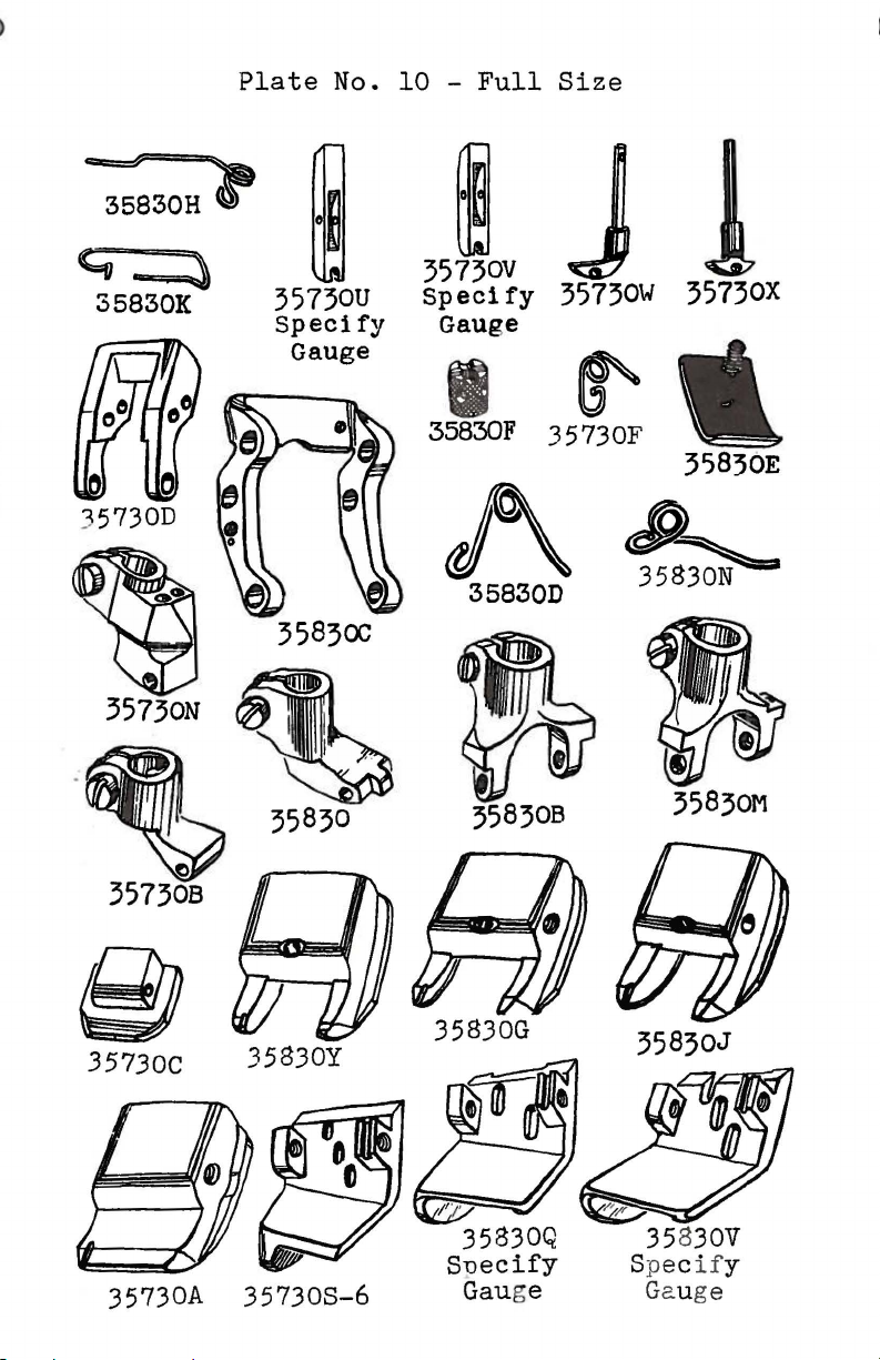
35830H..,
Plate
35730U
Specify
Gauge
No.
10 -Full
00
35730V
Specify
Gauge
Size
J
35730\./
35730X
35730D
35730C
35830C
35830
35830Y
I
35830F 3 5 73
~
~
358300
358308
35830G
OF
35836E
~
35~
35830M
35830J
35830V
Specify
35730A
357308-6
Gauge
Page 19
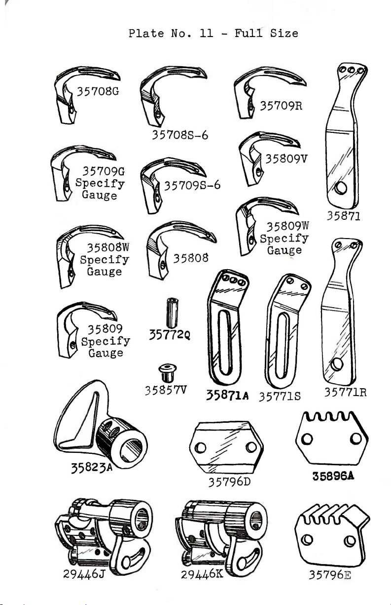
Plate
357088-6
No.
11 -
Full
Size
35871
m
35772Q
if
35857V
j5871A
35796D
357718
35771R
35896!
35796E
Page 20
Plate
No. 12 -
Full
Size
~
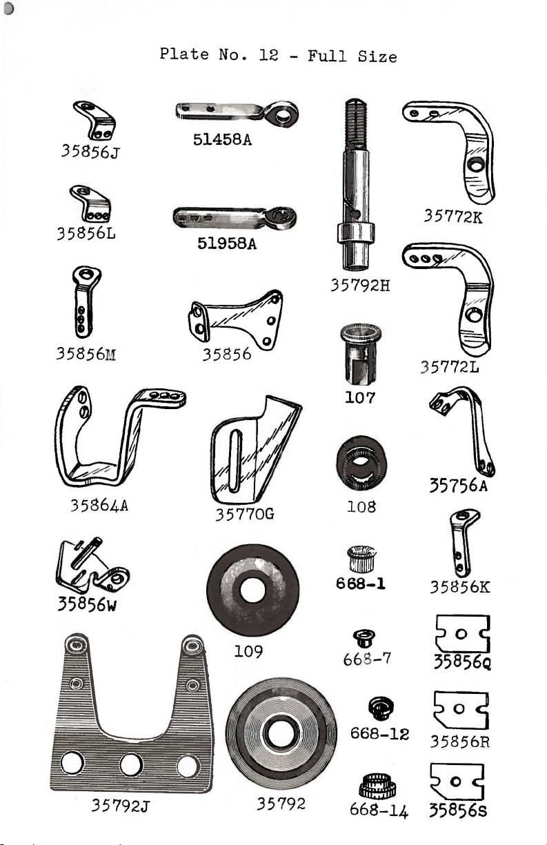
35856J
~
358561
35856
1!
35864A
51458A
35772K
51958A
35792H
357721
107
0
108
~
35856w
668-1
•
ffj
668-7
eG
668-12
o8
35792J
668-14
35856K
B
35856Q
35856R
35856S
r
Page 21
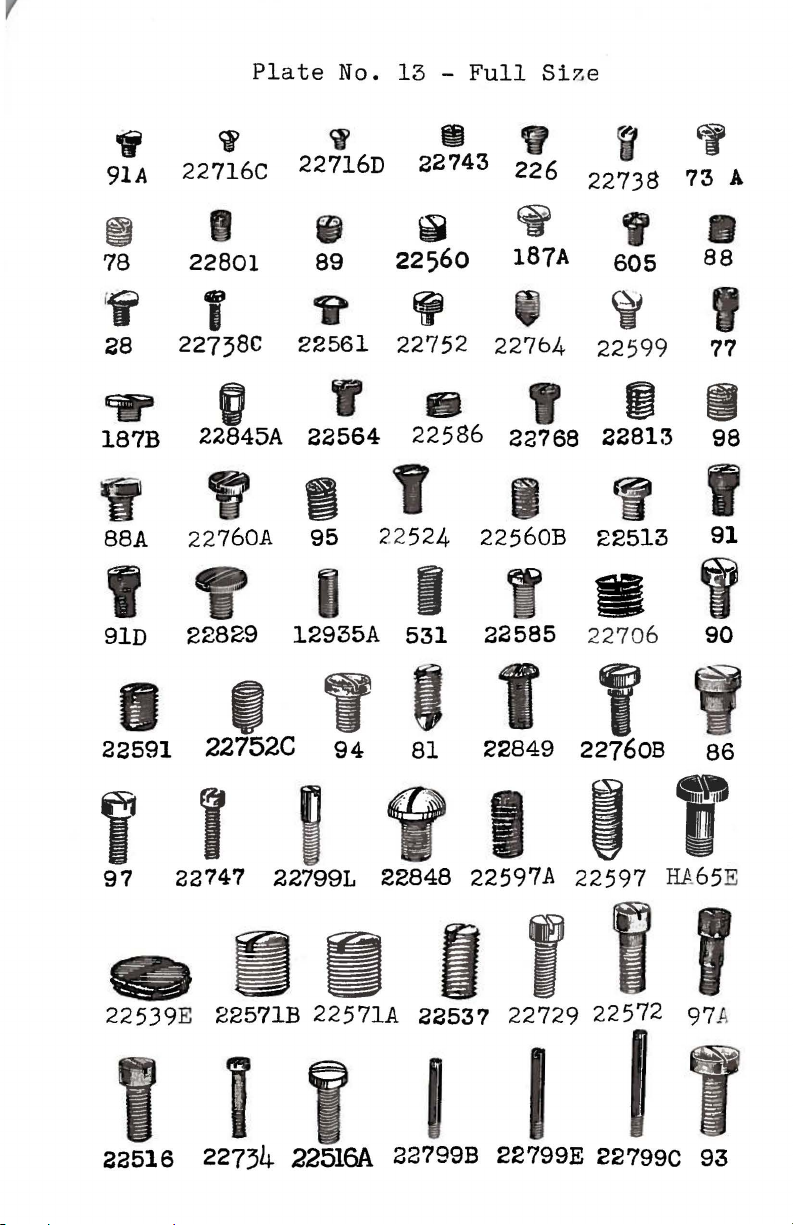
Plate
No. 13 -
Full
Si
ze
~
91A
'lr
187B
y
88A
I
91D
<i
22716C
22801
i
22738C
0
22845A
9
22
760A
22829
<f
22716D
il
89
~
22743
226
~
187A
rg
22738
I
605
~
22561
y
22564
22752
fi
22586
22764
22768
22599
1m
22813
I I W
95
12935A
22
524
I
531
22560B
22585
22513
22706
"
7'%
u
88
77
98
-
I
91
90
'
A
I I
22591
22752C
y I
97
22747
II
94
81
t f
22849
227608
i t I I
227991
22848
22597A
22597
H.A
86
65 E
'
1 r 1
22539
I i i
22516
E
22571B
22734
22571A
22516A
22537
22799B
22729
22572
I I
22799E
22799C
97
li
93
Page 22
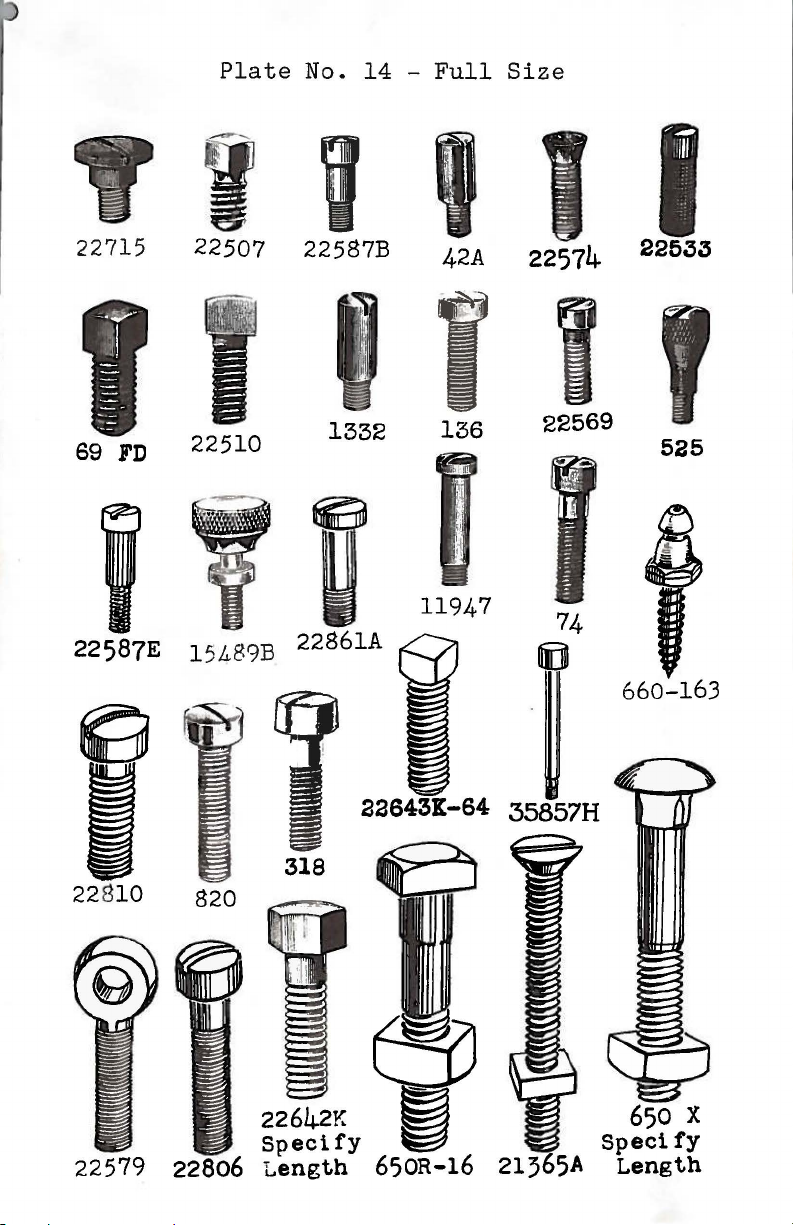
Plate
No.
14 -Full
Size
22715
sg
FD
22587E 15489B
I I '
22507 22587B
22510
1332
2286
lA
42A
22574
I I
136
11947
22569
.i4
I
22633
525
&
'
660-163
318
22810
820
22642K 650 X
Specify
Length
650R-16 21365A
Specify
Length
Page 23
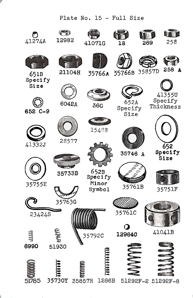
Plate
No.
15 -Full
Size
~
41274A
651B
Specify
Size
0
652
C-9
©
41
332J
@
~
'
12982
21104H
6042A
@
28577
35733B
eta&D
41071G
-
35766A 35766B
18
~~
~
36G
652A
Specify
Size
0
35746 A
652B
Specify
Minor
Symbol
@
35761B
269
35857D
258
~
258
A
4QU
Specify
Thickness
J @
652
Specify
Size
35751F
~
35761C
()
129640
~
6990
I
51785 35730Y 35857R 1286B
51930
I
51292F-2
41041B
51292F-8
Page 24

Plate
No. 16 -
Full
Size
35792K
664F
Specify
Minor
Symbol
35760C
35851G
~
35885A
12'3?3
35761
35853E
~
35834N
35
750A
6670-16
A m
~
35833F
1286
0
.3
5834G
~
12
~
6A
35763F
ll947B
3
35759A
35736A
35731B
35760B
35763
5125TB
5750C
35890A
35790E
Page 25

Plate
No. 17 -
Full
Si~e
35837N
35853N
35859G
35851
35837
35831B
35846
35851A
35755B
35731A
357510
35792E
12839
35751
35767
5288
7G
35732A
Page 26

35795E
Plate
0
21388Y
No. 18 -
Full
WA15
Size
21350
0
21351
Page 27

Plate
No. 19 - One-Half
Size
29101F
'3
5885
29103F
I
11946 119
29103G
45
35
35784
836
35853A
;5780D
..
54
0
35889A
35786
35889B
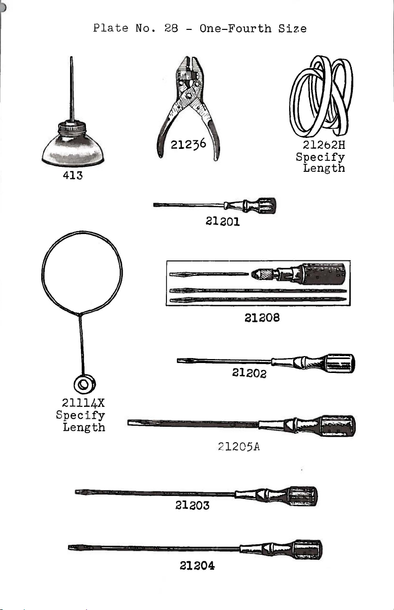
Page 28

Plate
No.
20 -One-Half
Size
I,
I I
35751B
35843
358330
35833E
35845
35842G
39141
35841A
II
I
I I
42~-
43246
35878
:~58781"
35717S
35817C
35717H
Speci
Gauge Gauge
fy
358170
Specify
Page 29

23422T
Specify
and
Capacity
Plate
Gauge
No. 21 -
23424T
One-Half
~
35833
Size
I)
21388AB
666-35
c
23421T
Specify
Capacity
and
Gauge
~
23421Y
Specify
Capacity
Gauge
and
t[jo
23423T
23420Y
Specify
Gauge
and
Capacity
23420T
Specify
and
Capacity
Gauge
trBO
23423U
Page 30

Plate
~;,::::~
No. 22 -
.!55{3!'5 &
(;.52. 24
- -
3b8!?J5M
One-Half
- .35cX'5 Q
.
""o-
"z
TA.BL.e:
TOP
~
-
c;,o -tr:.z
358!?J5 Q
Size
28579E
_ r:.sta -
Assembly No. 29401C
24
35776
IJ
28563
'
21398Q
421
524
22605
523
21398L
-
666-79
Page 31

Pl
at e No. 23 -
One-Half
Size
21388
(
~
\
118
B
R
21388
21388
N
21227HK
21698
21207
Specify
Length
TA55A
Page 32

Plate
No. 24 -
One-Fourth
Size
35888
I
357218
35887A
35884A
®
35721C
35887
35821B
0 0
0
35888A
35791A
35721A
Page 33

Plate
No. 25 -
One-Fourth
Size
35792L-4
35792G-4
357921-6
35792G-6
357'30C
•
•
35834
35844
357921
35849A 35722F
35822F
Page 34

666-16
Plate
No. 26 -
0
43294A
One-Fourth
Size
.,
29402
21104
SDecif
:
422
B
y
engtb
21231
Page 35

Y802
Y558
Plate
No
. 27 -
One-Fourth
Si
ze
13"
Y558
Speci
fy
Size
4~"
1
Y559
Specify
Size
r
u
Y561
Specify
Si
Y503
Specify
Size
1
Y561
F
Y501
Specify
Size
ze
Page 36
413
Plate
No. 28 -
-=~=Q[J;$~
One-Fourth
21201
Size
21262H
Specify
Length
21208
Q
21114X
Speci
fy
Length
21205A
21203
21204
Page 37
Plate
No.
29
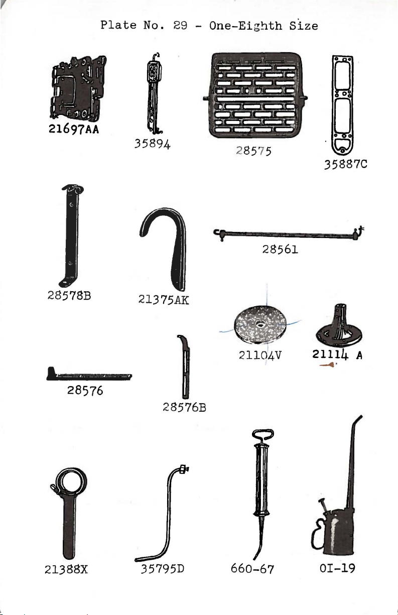
-
One-Eighth
Size
21697AA
28
578B
••
28576
35894
21375
,
AK
28576B
-r~:
---
~-
28575
7
:=
~
:~~~
·-·
---
....
28561
~~~:~,:r~'
:~
::_~
t~~
'
.-.,~-T-r-1"
r
~....-r~--
......
.,
-
jJ
-
.,;
...,..
\
--
0
0
'Q
35887C
~
21114 A
.......
.
21388X
35795D
660-67
OI-19
Page 38
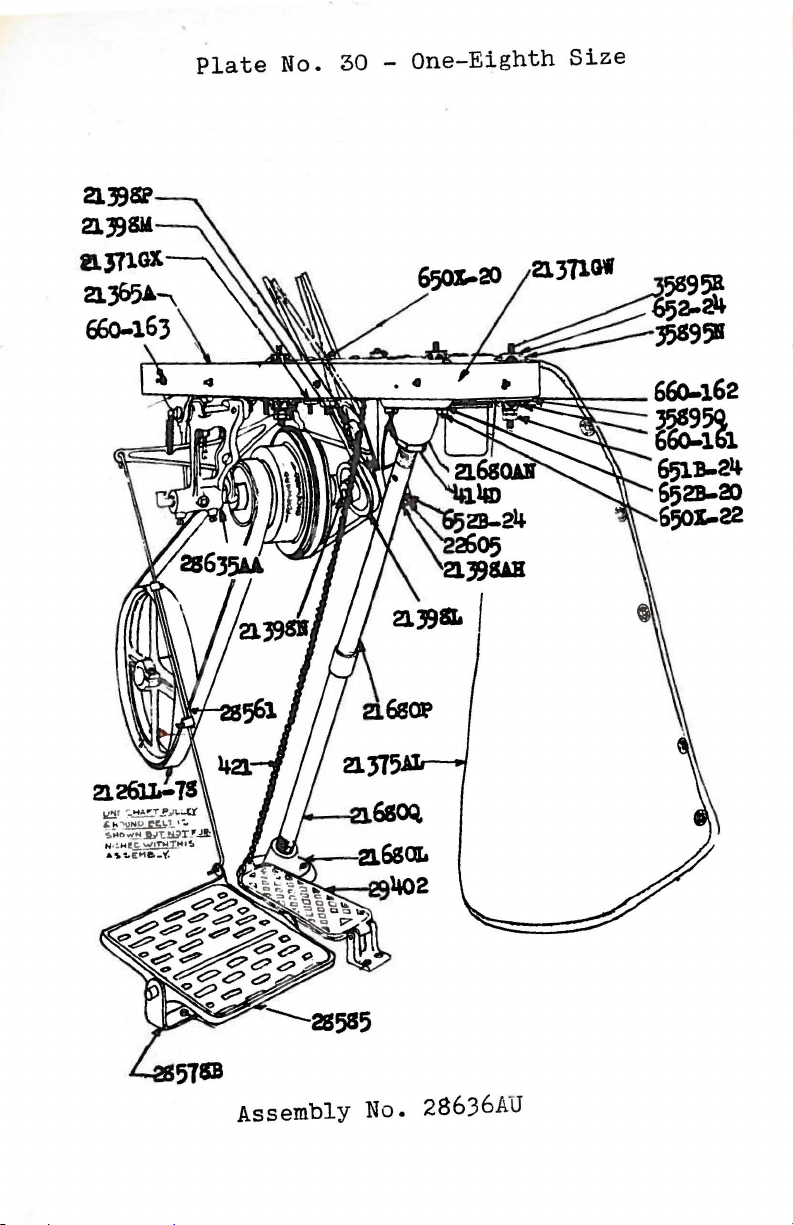
Plate
No. 30 -
One-Eighth
Size
Assembly No.
28636AU
Page 39

Plate
No. 31 -
One-Eighth
Size
*ELf.CTilO
~lYe
ASSEMBLY
10.
29470 T
Page 40

Plate
No.
32 -One-Eighth
Size
------
~~~~~~~~~~=~~~
2139SM
650X..20
2l31lGW
-
6Eio-162
651B-24
6528-a>
650%-22
,...._2l375AL
ASSEMBLY
HO.
29470 U
Page 41

...-
-.....
·21114H-4·
·Z.
I
104
·21114A
I
5Wo,
B-24
STYLE
-
668~-
·
668-14
·21
114K
ORDER
'
miD
"G"THREAD
z
~
;.
'
SECTION
FOR
OF
21227HK
MAKING
EYE.LET.
TOOL
RE.PAIR5
.
· I
·
211
14
H-6
STANDS
"'0
I-'
11'
c+
CD
z
0
CN
CN
I
0
::s
CD
I
t:J:j
,_,.
(TQ
P"
c+
P"
('J)
,_,.
1:'1
CD
ASSEMBLY
N2
21101G·4
ASSEMBLY
NQ
21101G-6
Page 42

Plate
No. 34 -
One-Eighth
Size
ell
~
I
:c
(J)
0
z
<(
t-
(j)
0
<(
w
a:
I
1-
•
I
•
w
_J
0
N
01
z
~
I
::c
0
-
N
>
1-
C/)
Page 43

Symbol
to
rd
er
By
LIST
The f i
gur
e i n
plates illnstrati!lg
used i n o
rder
the
i ng.
OF PART
last
column
the part
Refer
S
refer
and are
to insert
for
only
not
prices.
to
to
the
be
Plat
No.
e
WA15
18
OI-19
28
36 G
42 A
50
50 J-26
54
TA54
TASS A
HA65
69
73 A
74
77
78
81
86
88
88
89
90
91
91 A
91 D
93
94
95
97
J-16
E
FD
A
Stop
Watch-
Conne
ctin
Pressure
Screw,
- - - - - - - - - - -
Rod
Nut,
for
Pump
folder
Oil
Can, 1 1/2
upper
right
thread-
scroll;
pints
also
- - capacity
for
No. 35770 G - - - - - - - - - - - - - - Feed
Stop
Needle
35700
Rocker
Pin,
for
Stop
H,
Connecting
lifter
Pin,
35700
for
J,
Rod
lever
Styles
35700
Ball
link
35700
K,
Stud
- - -
35800
Washer
G,
C,
35800 D - - - - - - - - - - - - 7
Needle
35800
Stop
V,
Pin,
35800
for
W,
Styles
35800
X;
35700
also
S,
for
No. 128 9 - - - - - - - - - 7
Needle
Hand
Hand
Pivot
Screw,
Screw,
Screw,
Lever
TallyTachometer,
Stud,
square
diameter,
lon
g,
shaft
for
installations
for
also
for
for
Link
- - - - - - - - -
- - - - - - - - - - 2000
to
rear,
head,
18
idler
for
threads
pulley
lifter
cup
8000
point,
per
shaft
inch,
- - - - - - - - - - -
looper
Nos. 35830
lead-in
holder
H,
thread
thread
35830
eyelet;
R.P.M.-
lever
5/16
5/8
on
eyelet;
N,
- 23
link
- - 13
inch
inch
open
l i n
35856 W
also
for
No. 35792 E - - - - - - - - - - - - - - -
Set
Screw,
lever
Set
Screw,
Spot
Pivot
Set
Screw,
for Nos.
35751
Set
Screw,
Spot
Scre
Scre\v,
link
w,
Stud,
F,
for
loopers,
pin;
for
lower
for
main
front,
for
feed
29101
35823
for
needle bars-
for
needle
and
also
upper
for
needle
shaft
for
lift
F,
29103
A-
- - - - - - -
No. 35864
lever
coupling-
lifter
lever
F,
needle
link
lever
shaft;
29103 G,
- -
holder
s ;
also
A-
- - -
link-
also
for
- -
pin
No. 3 5751 F - - - - - - - - - - - - - - -
Screvr,
Clamp
Screw,
Clamp
Screw,
Screv
Set
feet;
feet-
t,
Scre
also
for
Screw,
also
for
Screw,
needle
looper
3/8
for
No. 35792
7/16
guard
inch
thread
inch
holde
long,
guard eye
long,
r - - - - - - - 13
for
H-
- - - - - - -
for
- - - - - - - - - - - - - - for
for
w,
for
crank
tension
for
Nos.
chamber
main
21114
post
shaft
X-~4,
cover-
support
and cra
21114
presser
lets-
- -
presser
- - - - - -
- - - - - nk shaf
t;
X-33,
35834 - - - - - - - - - - - - - - - - - - 13
Clamp
tion;
Screvr,
also
for
lift
for No.
er
lever
3585'
l i
nk
F-
- - - - - - -
connec-
P.
-
18
15
29
13
15
14
19
14
13
14
13
13
13
13
13
13
13
13
13
13
13
13
13
- 42-
Page 44

&
ymb
ol
to
Order
By
97 A
98
107
108
109
118
B
136
187 A
187 B
226
258
258
A
269
318
413
414 D
421
422
423
424
Y501-257
Y503-319
523
524
525
531
Y558-250
Y558
F
Y559
Y561-500
Y561
F
605
R-16
650
650 X-20
OF
LIST
The fig
plat
used i n
Bear
rod
ure
s i n
es illustrating
ordering.
ing
Screw,
ball
joint;
35837 N, 35841 B,
the last column
for
PARTS
the
Refer
looper
also
35846,
parts
and
to insert
drive
for
Nos.
35851,
refer
are
for
connecting
35837,
on y to
not
to
~rices.
35851
be
A,
35853 N- - - - - - - - - - - - - -
Set
Screw, 3/16
needlesTension
Tension
Tension
Thread
Screw,
Screw,
Screw,
Screw,
35700
Nut,
stud;
Thread
Post
Regulating
Disc,
Tweezers-
for
for
for
for
G,
for
also
Stand
Connecting
Screw,
lower,
feed
inch
long,
without
pilot,
- - - - - - - - - - - - Ferrule
lower-
- - - 12
Nut,
knurled-
- - 12
- - - - - - - - - - - - -
- - - - - - - - - - - 23
rear
tension
cylinder
needle
presser
holder
cover
foot
release
spring
thread
spring
shaft
hanger -14
- - - - -
guide-
on
- - - -
Styles
35700 H - - - - - - - - - - - - - - 13
lift
Rod
for
No. 35841 B - - - - - - - - -
Cone
Holder
Nut,
for
detachable
lever
left
connecting
Pin
Lock
thread-
head
rod
Nut-
- - - -
- - - - - - (washer
6042 A)- - - - - - - - - - - - - - - - - - -
Oil
Can,
Lock
Nut,
sion
Lifter
"
right
brace
Lever
Treadle
column-
Chain,
" "
" "
complete-
Expansion
Reamer,
" "
Cylinder
Set
35751 B, 35842
Expansion
section
Ferrule,
Expansion
section
Expansion
all
Ferrule,
Screw,
Machine
light
stallationsCarriage
pulley bra
install
Cover
" " "
" " " Knob - - -
Scre1,
for
Reamer,
of
looper
for
expansion
Reamer,
of
looper
Reamer,
31
inches,
for
for
expansion
looper
Bolt,
fixture
Bolt,
cket
at i
ons; also
- - - - - - - - - - - - - - 28
thread,
for
table
top
exten-
- - - - - - - -
38
inches
long
- - - 22
- - - - - - - - - - - - - - - - 26
BasePin
Bolt-
needle
square hea
- - - - - - - - - - - - - 22
(screw
size
bar
size
bar
No. 22813) - - - - - 20
.257
bearings
.319
inch,
inch,
for
- - - - - - - - 27
for
bearings
- - - - - -
Spring
G, 35845,
size
shaft-
size
shaft-
size
for
main sha
rocking
rod
clamp on
- -
lever;
also
for
41041 B - - - -
.250
inch,
for
- - - - - - - - - - 27
reamer
.375
No.
inch,
Y558-250
for
- - - - - - - - - - 27
.500
reamer
pin
d,
3/8
inch,
length
ft bea
rin
No. Y561-500 27
holder
x 2
line
- - - - -
inches,
assembly in-
needle
presser
Nos.
rear
front
gs - - - 27
- - - - - - - - - - - - - - - 5/16
x 2
1/2
support
for
inches,
on open
No. 21371
line
for
sha
GX
idl
- - - -
-43-
the
for
ball
No.
ove
f t
- -
r-
for
er
P
late
No.
13
13
12
13
13
15
15
15
14
27
- 22
22
- 14
13
2'i'
13
14
14
Page 45

Symbol
to
Order
By
The
plates
used
figures
illustrating
in
order
LIST
i n
i ng.
the
OF
last
the
Refer
PARTS
column
parts
to
refer
and
insert
are
for
only to
not
to
prices.
the
be
Plate
No.
650 X-22
651 B-24
652-16
652-24
652 A-20
652 B-20
652 B-24
C-9
652
660-67
660-161
660-162
660-163
664
F-16
664
F-24
666-11
666-16
666-17
666-35
666-46
666-79
666-81
667 D-16
668-1
668-7
668-12
668-14
698 BC-8
Carriage
top
Nut,
stud
Thread
Bolt,
extension
3/8
inch,
5/16
x 2
upper
brace
hexagonal,
3/4
inches,
flange
for
- - - - - -
cushion
for
mountin
- - - - - - - - - - - - - - - - - ·- - Stand
Cone
Holder
Pin
Washer;
also
No. 21114 U-- - - - - - - - - - - - - - - -
Washer,
also
Lock Washer,
screw-
Shake-Proof
pulley
and American
Shake-Proof
pulley
American
for
Shake-Proof
Oil
Cushion
table-
Cushion
Dress
Taper
tachable
Taper
cating
Oil
cover-
Reservoir,
Oil
shaft
Felt
cup
Oil
Oil
stop,
Felt
toggle
Dowel
locating
Porcelain
also
21114
Porcelain
Porcelain
thread
Porcelain
lead-in
21114
Test
g
3/8
inch,
for
No. 29469 D - - - - - - - - - - - -
for
for
sound
cushion
insulator
mounting
attachin
- - - - - - - - - - - - - - - - - - Lock
bracket
Washer,
Safety
Lock Washer,
bracket
on
Safety
support
Table
5/16
on open
Table
3/8
open
line
installations;
inch,
for
line
installations-
inch,
shaft
for
and
No. 29469 D- - - - - - - - - - - - - - -
Gun,
for
Felt
Washer,
removing
Tube,
for
for
oil
from
attaching
needle
cylinder-
machine
bar
Lock
- - - - - - - - - - - - - - - - - 22
Felt
Guard
Dowel
Dowel
Cup,
WasherFastener
Pin, 1 inch
head-
Pin, 1 1/4
cylinderpress
fit,
- - - - - - - - - - - - - 22
Screw - - - - - - - - - -
long,
for
locating
- - - - - - - - - - - - - - inches
long,
for
- - - - - - - - - - - - - - 16
for
rear
main
frame
- - - - - - - - - - - - - - - - - - -
Cup,
for
installations-
Pad,
on
styles
Cup,
press
Cup
Assembly,
for
Wick,
glass,
for
main
for
for
idler
pulley
upper
in
Class
fit,
with
oil
differential
oil
drain
shaft
assembly
on open
- - - - - - - - - - - -
needle
thread
lubricating
35800 - - - - - - - - 21
for
crank
sight
reservoir
chamber
feed
and
- - - - - - - - 22
looper
motion
- - - - - - - - - - - - - - - - - - -
Pin, 1 inch
for
S-4,
eyelets
H-6,
Plate,
au
ge
Styles
cylinder-
Insert,
Nos. 21114
Insert,
Insert
Insert
eyelet;
for
long,
Danley
standard,
- - - - - - - - - - - - -
for
21114
thread
H-4,
S-6
for
tension
Locking
- - - - - - - - - - - -
lead-in
21114 H-6,
thread
Ferrule,
eyelet;
eyelet-
for
- - - - - - - - - - - - - - -
21114
setting
Locking
also
S-4,
Ferrule,
for
Nos. 21114
21114
needle
S-6-
bar
for
- - - - - -
on No. 8
35700 G,35700 H,35700 J,35700 K 6
stud;
shaft
idler
also
cover--18
signal
tension
thread
H-4,
-44-
table
g
for
g
idler
- -
eyelet
- 29
to
delotop
- - - 26
line
for
-
14
15
15
15
15
15
15
15
14
16
18
18
18
16
12
12
12
12
Page 46

LIST
OF
PARTS
Symbol
to
Order
By
698 BC-10.
698
BC-12 " "
The
plR.tes
used i n
Test
698 BD-12 " "
698 BD-16
698 BD-18
698 BF-6
698
BG-8
698
BG-9
699 c
n
"
"
"
" "
Test
35700
35700 s - - - - - - - - - - - - - - - - - 6
699 D
Test
35800 C, 35800
35800 X - - - - - - - - - - - - - - - - - 6
Y802
820
Taper
Screw,
6042
1286
Needle
Nos. 1286
1286 A
Needle
link
link
1286 B
Needle
22560)-
1332
Hinge
screw
6042 A
Washer,
attaching
6990
Cylinder
Sprin
7018
E-5
Needle
35800 C
screw
7040-6
Thread
on No. 18 gauge
No. 187
11945
11946
11947
11947 B
12839
Feed
" " " "
" " "
" n " "
Lifter
No. 97) - - - - - -
12873
12935 A
12964
c
12982
Needle
Screw,
Needle
Differential
also
figur
es i n
the
illustrating
order
Plate,
"
"
n
"
last col
i ng.
for
for
for
the
Refer
No. 10
No.
setting
12 gauge
for
No. 16
for
No. 18
for
setting
gauge
for
gauge
Style
setting
Styles
umn
refer
only
parts
to
gauge-
12
gauge-
Styles
gaugegauge-
and
are
insert
for
- - - - - - - 6
- - - - - - - 6
needle
35800 C,35800 D
- - - - - - -
- - - - - - -
needle
qot
bar
bar
to
to
prices.
on No.
on No. 6
35700 S - - - - - - 6
needle
35800
bar
V,
on No. 8
35800
35800 X - - - - - - - - - - - - 6
for
Pin,
for
G,
Pin,
for
Reamer,
for
A)
- - - - - - - - - - - - - - - - -
Lever
Lever
pin,
pin,
Lever
No. 9 gauge - - - - - - - - 6
setting
35700
setting
for
attaching
Link
A,
1286 B, 12964 C, 22560 - - -
Link
No. 775 set
needle
H,
35700
needle
D,
35800
needle
cylinder
Pin
Assembly; one
Pin
(set
J,
V,
lever
screw
screw
bar
on
35700
bar
on
35800
link
(washer
for
for
Styles
K,
Styles
W,
pins-
No.
each
upper
lower
No. 78 - - - - - - - - - - - - 16
Link
Pin
Spring
(screw
No.
- - - - - - - - - - - - - - - - -
Pin,
for
presser
spring
regulating
- - - - - - - - - - - - - - - - - for
cylinder
screws-
Looper
g,
for
Holder,
(spot
styles
for
and
detachable
- - - - - - - - -
Thread
Tension
in
Class
No. 18 gauge
screw
No.
89,
head
Plate
35700 - - - -
Style
needle
set
No. 98) - - - - - - - - - - - - - - 7
Guide,
Lift
Lever
Bar
rear,
Lever
for
detachable,
Style
B)-
- - - - - - - -
Lever
Link, rig
Link
Link
Connection
Bushing,
for
supporting
Link
Pin
Looper
Nos.
2275~
for
35800 C
ht
leftStud
Bushing-
--
lower
Ball-
Motion
needle
- -
- - -
- - - - - - -
- - -
(clamp
-
--
- - - - - 16
feed
- - - - - - - -
Ball
(screw
screw
- dog-
Stud
holder
Nut;
c, 35755 B- - - - - -
- - -
the
be
W,
- -
Plate
6
- 27
14
16
15
14
-
15
15
7
-
19
19
14
16
17
13
15
15
No.
6
6
-45-
Page 47

Symbol
to
Order
By
The
plates
used
LIST
figures
in
in
illustr~ting
order
ing.
the
OF
last
Refer
PARTS
the
column
parts
to
insert
refer
and
are
for
only
not
prices.
to
to
the
be
Plate
No.
15488
15489 B
21101 G-4
21101 G-6
21101 H-4
21101 H-6
21104 B-24
21104 H
21104 v
21106 E
21114
21114 A
21114 D-4
21114 D-6
21114 H-4
21114 H-6
21114
21114
K
S-4
Looper
Thumbscrew,
Thread
Thread
Thread
Thread
Thread
Shaft
Washer,
Stand
four
cones;
21104
21114
four
No. 21114
No. 258
Stand
six
cones;
21104
21114
six
No. 21114
No. 258
Stand
four
spools;
21104
21114
four
five
B-24,
S-4,
each
No.
Stand
six
spools;
21104
21114
six
seven
B-24,
S-6,
each
No.
Stand
Cross
right-
for
Head
- - - - - - - - - - - -
left
Assembly,
one
B-24,
S-4,
A;
each
21104
H,
21114 T, 22810; two
W;
twelve
five
No. 21114
Assembly,
one
B-24,
S-6,
A;
each
21104
H,
21114 T, 22810; two
W;
seven
eighteen
Assembly,
one
each
21104
21114
Nos.
652-16;
H,
T,
2110~
eight
Assembly,
one
each
21104
H,
21114 T, 22810; two
Nos. 21104
652-16;
twelve
Rod, 24
Link
Ball
Joint
detachable
Style
Nos. 21114
21114
G,
A,
head
for
use
D-4,
21114
cover
H-4,
No.2lll4
No.
652-16;
V-
Style
G,
Nos. 21114
21114
A,
eight
- - - - - - 33
for
use
D-6,
21114
H-6,
No.2lll4
No.
No. 21114
652-16;
Style
H,
Nos. 21114
21114
A,
22810; two
V,
21114, 21114
twelve
V-
- - - - - 33
for
use
D-4,
21114
H-4,
No.2lll4
No. 258 A - - - - - 34
Style
Nos. 21114
21114
H,
A,
for
use
D-6,
21114
H-6,
No.2lll4
V,
21114, 21114
W;
No. 258 A - - - - 34
inches
long
(set
screw
with
with
with
W;
with
No. 22591) - - - - - - - - - - - - - - - - 26
Nut,
for
lead
11G11
Felt
Spool
Spool
Base,
and 11H
Pad, 5 l/4
seat
disc
Cap,
Seat
for
(screw
Seat,
for
thread sta
Seat,
for
thread
Eyelet
Eyelet
11G11
Support,
and 11H
Support,
and 11H
Porcelain
on
Styles 11G
Eyelet,
Lead
Styles 11G
lain
11
insert
eyelet
11
thread
on
for
Disc,
Style 11G
No.
22591)-
four
nds
six
cones,
stands
11
thread
thread
Insert
11
adjustable,
11
and 11H
No.
Style 11H
small
cones,
~~~~~l~)N~--6~8=1~,
ball
socket
stands-
inches
diameter,
11
thread
spools-
for
Style 11H
11
and 11H
11
- - - - - - - - - - - - 29
on
(screw
(screw
for
No.
on
No.
four
Styles 11G
22591)-
Styles 11G
22591)-
cones,
stands
for
six
11
thread
cones,
(screw
t,
11
thread
for
for
insert
stands
Gaske
and 11H
668-l,
-~s=r~
on
- - - - - - - for
stand-
- - - - - - - - 18
11
thread
thread
stand
11
- - - - - 33
11
and
- - - - - 33
on
(screw
Styles
No. 2259lJ 34
on
Styles 11G
No.
22591)-
eyelet
stands-
four
stands
cones
(porce-
lockin
~a~k=t-N~·-
Styles
spool
- - - 29
stand
and 11H
"H"
support
- - - 33
on
g
__
-46-
15
14
U;
U;
U;
U;
15
34
11
11
- 34
34
Page 48

Symbol
to
Order
By
The
plates
used
LIST
figures
illustrating
in
ordering.
in
the
OF
last
Refer
PARTS
the
column
parts
to
insert
refer
and
are
for
only
not
prices.
to
to
the
be
Plate
No.
21114
S-6
Lead
Styles 11G
lain
ferrule
21114
21114 T Lead
21114
U Lead
11H11
tion,
stands
21104
21114
V Cone
stand
21114
W
Spool
stands-
21114 X-24
21114 X-33
Thread
6
11811
Thread
8
11H11
21201 Screw
overall 7 5/8
21202 Screw
overall
21203 Screw
length
21204 Screw
overall
21205 A Screw
overall
21207 Screw
overall 2 1/2
21208 Screw
21225-1/8
Looper
ment-
21227
HH
Porcelain
assembling
porcelain
ferrules
eyelet
be
21227
HK
Porcelain
assembling
porcelain
ferrules
eyelet
21114 H-6, 21114
Ferrules
21231
Thread
of
the
Eyelet,
insert
Eyelet
thread
Eyelet
Holder
adjustable,
11
and 118
No.
K)-
- - - - - - - - - - - - - - - - 34
Socket
11
No.
668-1,
668-14,
Ball,
stands
Ball
for
(clamp
H,
washer
Split
Styles 11G
screw
No.
Spring,
thread
insert
(screw
Socket,
11
and
No.
652-16)
for
Style 11G"
for
six
cones
stands
insert
gasket
for
Styles 11G"
(porce-
locking
No.
No. 22591) - - - 33
half
11811
22810,
sec-
thread
nut
- - - - - - - 33
thread
- - - - - - - - - - - - - - - - - - 33
Pin,
for
Styles 11G"
and
"H"
thread
- - - - - - - - - - - - - - - - - 33
Guide
inches,
thread
Guide
1/4
thread
Driver,
Driver.,
Driver,
Driver,
Driver,
Driver,
Driver
Adjusting
Ring,
for
Ring,
inches,
stands
11
1/4
overall
15
14
Set,
four
stands
for
9/64
inches-
7/32
inches
13/64
15
9/32
inches
3/8
inches
7/64
inches-
Gauge,
distance
cone
(screw
distance
six
(screw
inch
Styles
No.
cone
No.
round
between
"G"
95)-
between
Styles 11G
95)-
blade,
centers
- - - - 28
centers
- - - - 28
- - - - - - - - - - 28
inch
round
blade,
- - - - - - - - - - 28
inch
1/2
inch
round
inches-
round
blade,
- - - - - - 28
blade,
- - - - - - - - - - - - 28
inch
round
blade,
length
- - - - - - - - - 28
inch
round
blade,
- - - - - - - - - - 23
three
detachable
1/8
inch
blades
measure-
- - - - - - - - - - - - - - - - - - 6
Insert
No.
assembly.
replaced
Insert
No.
assembly;
should
Meter,
thread
sewing
1/16
inserts
668-12
Replacement
inch
internal
No.
in
Ferrules
668-7
tension
Tool
Set,
diameter
and aluminum
thread
should
always
- - - - - - - - - - - - - - - 23
Replacement
1/8
inch
inserts
668-14
also
S-4,
always
for
in
recording the
1/10
mach~ne-
internal
No.
in
yards
- - - - - - - -
Tool
668-1
thread
for
Nos.21114 H
21114
be
replaced-
as
it
Set,
diameter
and a
lumin
lead-in
S-6.
consumption
passes into
-47-
on
and
No.
and
11
and
length
length
length
length
- 28
for
for
um
-4,
- - - 23
26
Page 49
Symbol
to
Order
By
The
plates
used
figures
illustrating
in
order
LIST
OF
in
the
last
i ng. Refer
PARTS
column
the
parts
to
refer
and
insert
are
for
only
not
price
to
to
s.
the
be
Plate
No.
21233 N
21233 p
21233 X
21233
y
21233 z
21236
21260
21260
A
21260 B
21260 c
21260 D
21260 E
21261 L-78
21262 B-53
21262 B-69
21262 B-77
21262
H-510
21262 H-520
21262 H-530
21262 H-540
21350
21351
21365 A
21371
21371
21371
21371
GU-42
GU-48
GU-54
GU-60
Connector,
"Electro
Connector,
three
Light
blue
driven
Light
clear
Light
without
NOTE:
blies
table,
with
Drives"with
phase
Fixture
lens,
by
Fixture
lens-
Fixture
lensWhen
to
be
order
BX
cable
for
D.C.
- - - - - - - -
BX
A.C.
Assembly,
table
"Electro
Assembly,
cable
"Electro
mounting,
for
including
Drive"
including
single
Drives"
for
machines
- - - - - - - -
- - - - - - - - - - - - Assembly,
including
- - - - - - - - - - - - - -
ordering
mounted on
as
extra
light
one
line
fixture
assembly
set
of
and
bulb
bulb
bulb,
assem-
clamps
No. 29469 D - - - - - - - - - - - - - - -
Belt
Plier,
belting
Emery
120,
Emery
150,
Emery
180,
Emery
200,
Emery
fifty
Emery
200,
Leather
inches
Cord,
Cord,
Cord,
Cord,
Tape,
Cord,
for
3/8
inch
and
smaller
- - - - - - - - - - - - 28
3/64
inch
fifty
fifty
fifty
fifty
yard
fifty
Belt,
long,
yard
3/64
yard
1/32
yard
.025
yard
3/32
spool-
.018
yard
flat,
including
diameter,
spool
inch
spool
inch
spool
inch
spool
inch
- - - -
diameter,
- - - -
diameter,
- - - -
diameter,
- - - - - - -
wide,
- - - - - - - - -
inch
diameter,
spool
- - - - - - - - - -
1
1/4
inches
belt
grade
fastener
grade
grade
grade
grade
No.
grade
wide,
No. 21350 - - - - - - - - - - - - - -
Leather
inches
Belt,
long,
round,
including
9/32
inch
wire
diameter,
belt
hook
No. 21351 - - - - - -
Leather
"V"
" " 52
"
" " 54
Belt
inch
Belt
Stove
for
Table
Safety
Table
rr
11
Belt,
"
Belt,
" 77
No. 2
circumference
" 53
Fastener,
flat
Hook,
Bolt,
transmitter
Top, 42
Table
Top, 48
" 54
11
inches
inches
inches
belt-
wire,
flat
11
inches
60
inches
69
inches
inches
size,
51
longlong-
inches
- - - - -
- - - - outside
- - - - · - - - - 28
outside
outside
outside
malleable
circumference
circumference
circumference
iron,
for 1 1/4
- - - - - - - - - - - - - 18
for
9/32
inch
head,
No. 28635
x 16
group
inches
11
x 1
angular
long
long
long
1/4
3/4",
roun
x 2
1/4 inches,
AA-
- - - - - -
for
American
installations
- - - - - -
- - - -
- - - - - - - - -
-48-
and
and
but
round
No.
No.
No.
No.
180,
No.
78
belt-
53
- 28
- 28
- 28
18
14
Page 50

LTS'I'
OF
PARTS
Symbol
to
Ord
er
21371
21371
21371
21371
21371
21371
21371
21371
21371
21371
GV-42
GV-48
GV-54
GV-60
GW
GX
GY-42
GY-48
GY-54
GY-60
21372 X
21375
21375
AK
AL
21388
21388 N
21388 R
21388 X
21388
21388
y
AB
21394
21394 G
21394
H
21394 K
21396
21396
21396
AG
AK
BE
21398 L
21398 M
By
The
figures
plates illustrating
used
in
Table
"
II
II
Table
11 11 11
Table
in
order
Top, 42
line
II
48
II
54
II
60
Top
Extension-
Top, 42
ing.
11
11
Drive group
Table
Light
Machine
Dress
Wrench,
Top, 48
11 11
11
Fixture
plain
652
B-24)-
Guard,
II
54
11
60
washer
Pulley
single
double
- - - - - - - - - - - - - - - 23
cloth,
openings
"
"
Spanner
ment
Wrench,
hollow
Table
Utility
inches
belt
3000
Emery Wheel,
face,
double
openings
for
main
Wrench,
lock
nut-
3/16
inch
set
screw
installationsGrinder,
diameter,
drive,
R.P.M.-
5
3/8
inch
Emery Wheel, 5
face,
Utility
inches
belt
3000
Felt
3/8
Grinder,
drive,
R.P.M.-
Pad,
inch
diameter,
for
lubricating
Needle
Needle
Idler
Idler
Thread
styles
Thread
Styles
35800
35800 C, 35800
W,
Pulley,
American
Pulley
in
Class
35800 X
Safety
Bracket
lock washer
the
last
the
Refer
x 16
shaft
inches
inches
inches
11
column
parts
x 1
long-
longlong-
ref
er o
and
insert
3/4
11
are
for
,
for
to
installations-
-
- -
- -
nly
not
prices.
open
to
to
- - -
- - - -
11
x 16
angular
inches
inches
inches
Rod
Clamp
No.
652-24,
Guard
end,
end,
Mounting
No. 650
x 1
installationslonglong-
lon~-
(screw
including
3/8
3/16
3/4
P1ate
X-20)-
11
,
for
(bolt
Electro
- - - - - -
- - - - - - - -
- - - - - - - -
(bolt
lock
No.650
washer
No. 22574) - - 29
fasteners-
inch
opening
and
5/16
inch
R-6,
- - - 23
- - - - - - - - - - -
end,
3/8
and
1/2
inch
- - - - - - - - - - - - - 23
shaft
for
bearing
looper
housing
throw-out
seg-
- - - - - - - - - - - - - 18
hexa~on,
on
for
American
3/8
inch
Safety
- - - - - - - - - - 21
includin
1/4
recommended
g emery
inch
speed
face,
wheel,
round
- - - - - - - - - - - - - inches
inches
recommended
diameter,
hole,
diameter,
hole,
includin
1/2
grade 11M
grade 11M
g emery
inch
face,
speed
1/4
inch
11
emery 60
1/2
inch
11
emery 60
wheel,
round
- - - - - - - - - - -
lower
cupLubricating
Lubricating
for
No. 652
needle
thread
- - - - - - - 21
Cup,
35800-
(screw
open
line
Table
(scr~~
B-241-
- - - - - - - - - 21
D,
installations-
upper,
Cup,
lower,
35800
No.
shaft
No.
V,
22829)and
22605,
- - - - - - - 30
-49-
the
be
No.
- 30
- - 29
5
5
for
for
- - 21
- - 22
Plate
No.
--
23
Page 51
LIST
OF
PARTS
Symbol
to
Order
By
21398 N
21398 p
21398
21398
Q
AH
21680 L
21680 p
21680 Q
21680
21697
AN
AA
21698-2
21698-4
21698-5
21698-6
22507
22510
22513
22516
22516 A
22524
22533
22537
22539 E
22560
22560
B
22561
22564
22569
22571 A
22571 B
The
figur
plates
used i n
Idler
Pulley
screw
Idler
Idler
Table
Table
2
2591)-
11
II
II
Pulley
Pulley
Top
Top
No. 650
Belt
Take-up
belt
Vibration
tables-
Vibration
11 11
11
NOTE:
request.
the
Set
illustration
Screw,
diameter,
long,
Cap
Screw,
threads
mission
Screw,
II
II
II
Lock
Screw,
toggle
Set
Screw,
toggle
Plug
Screw,
pin
Screw,
Set
hole
11
II
Screw,
Screw,
Plug
Screw,
11
es i n
illustrating
ordering.
the last
Shaft
No. 22
586)-
Shaft
column r efer only
the
parts
Refer
to
insert
(set
screw
and
are
for pri
No. 69
not
to
to
ces.
FD,
the
be
plug
- - - - - - - - - - - - - 30
Collar
(set
screw
No.
- - - - - - - - - - - - - - - - - - 30
Bushing-
11
Bracket
650
Extension
11 11
II
II
Extension
X-22,
lock
and Hanger Assembly,
installations-
Insulator,
- - - - - - - - - - - - 22
Support
X-20,washer
Brace
Brace
tion
Brace
tion,
Brace
washer
(bolt
No.
No. 652
Flange,
Column,
(lock
Column,
including
Flange,
nut
lower
upper
No. 414
lower
coupling
upper
No. 652 B-20) - - 30
for 11V
- - - - - - - -
two
inches
long,
B-20)-
- - - 30
sec-
sec-
(bolt
11
- - 29
for
- - - - - - - - - - - - - Insulator,
Special
square
for
square
per
treadle
for
needle
11
Part
20
threads
treadle
inch,
four
five
six
lengths
of
the
for
head,
pitman-
head,
5/8
pitman
rear
inches
inches
inches
will
table
long
long-
be
furnished
leg
clarity
cup
point,
per
inch, 3/8
- - - - - - - - -
1/4
inch
inch
diameter,
long,
bracket-
guard;
also
lon
g -
- - - 23
-
is
shown
l/4
inch
inch
for tra
- - - - - for
No.
on
ns-
35731 A- - - - - - - - - - - - - for
main
for
main
No.
35894countersunk
head
cover;
for
guide
guide
for
for
guide-
for
35800
for
II
stud
for
differential
stud
for
needle
in
bed - - - - - - - - - - - needle
presser
- - - - - - - - - - - - - -
presser
D,
35800
for
looper
crank
for
front
for
s i
frame
frame
differential
end
top
cover
covers;
- - - - - - also
for
- - - - - - - - - - - - - head,
also
for
front
for
No. 35767 - - - -
detachable
looper
motion
- - - - - - - - - - - - looper
motion
- - - - - - - - - -
lever
bar
foot
shaft
~ht
lever
lifter
V,
holder
bushing housingend
feed
connecting rod
link
pin
bracket
sprin
gs on
35800
W,
ass
of
cylinder
oil
er
sprin
g - - -
and
Styles
35800 X - -
embly - -
-
- - - -
hol
e - - 13
-50-
- 30
D)
- 23
in
20
- 13
Plate
No.
30
30
23
23
14
14
13
13
13
13
14
13
13
13
13
13
14
13
Page 52

LIST
OF
PARTS
Symbol
to
Order
By
22572
22574
22579
22585
22586
22587 B
22587 E
22591
22597
22597
A
22599
22605
22642 K-112
22643 K-64
22706
22715
22716
c
22716 D
22729
22734
22738
22738
c
22743
22747
22752
22752
c
The
figures
plates
used
Clamp
Screw,
illustrating
in
Screw,
thrust
ordering.
collar;
for
No. 21375
Presser
Screw,
Plug
shaft
Bearing
rod-
Screw,
looper
for
Set
Spring
for
Screw,
on
Screw,
- - - - - - - - - - - - - - for
avoid
No. 35780 D- - - - - - - - - - - - -
Screw,
Nos. 21114
21114
Spot
H-6,
Screw,
Nos. 35895
Set
Screw,
Screw,
Screw,
tion
35700
35800
line
for
equalizing
S,
X-
for
shaft
stallations-
Screw,
Adjusting
for
Screw,
sulator-
Plug
Screw,
Screw,
Screw,
Screw,
Clamp
Screw,
Screw,
Set
Clamp
Set
platetions
tions
35800
Screw,
rod
pin-
on
Styles
"
Screw,
ball
Screw,
rod
ball
Screw,
for
- - - - - - - - - - - - - - - - -
for
on
for
on
D,
for
for
for
stud-
on No. 6 gauge
and 9 g
35800
Set
auge
X-
Screw,
in
the
last
column
the
parts
Refer
for
looper
also
machine
AK
pulley
- - - - - - - - - - - - - Regulating
throat
for
open
oil
line
for
plates
hole
needle
refer
only
and
to inse
shaft
for
No.
rim;
Screw-
are
t
fo~
not
pr
cross
35836-
also
- - - - -
to
to
i cAs.
head
for
- - - - - - - - - 13
in
shaft
idler
installations
lever
pulley
connecting
the
be
- - -
Plate
13
14
14
13
14
feed
lift,
eccentric
feed
bearings;
rocker,
and
also
14
for
thread
D-4,
21114 T, 21398
for
machine
H,
35895
for
machine
presser
35800
21114
foot
spring
D,
35800
stand
D-6,
pulleys;
J-
- - - - - -
pulleys
bottom
on
Styles
V,
rod;
also
21114
P-
H-4,
- - - - - -
also
- - - 13
front
35800
sec-
W,
for
13
for
13
- - - - - - - - - - - - - - 13
idler
main
- - - - - - - - - - - - - - - transmission
throat
Styles
throat
Styles
35800
- - - - - - - - - - - - - - - -
presser
looper
feed
for
stud-
with
and
pulley
American
bracket
Safety
on
Tabl e
open
in-
- - - - - - - - - - - - - - 22
for
for
35700
feed
frame
rear
dog
sound
for
main
end
treadle
plate
35700
plate
35700
V,
needle
J,
holder
35800
foot
35700
needle
G,
needle
s,
lever
shank
thread
supplementary
rocker
insulator-
frame
of
sound
cylinder
locking
hole
sec-
35700 H - - - -
hole
sec-
35800 C,
W,
35800 X - - -
connecting
stop
--
ferrule
- - - -
K-
eyelet
section
connecting
- -
in-
- - -
- - 13
rod
- - - - - - - - - - - - - - - 13
for
feed
rocker
connecting
- - - - - - - - - - - - - 13
pilot,
Style
Styles
for
middle
needle
35700 S and Nos. 8
35800
V,
35800
W,
14
14
13
14
13
13
13
13
13
- - - - - - - - - - - - - - 13
for
cylinder
end
cap
latch
pi n • 13
-51-
No.
Page 53

LTST
OF
PARTS
Symbol
to
Order
22760 A
22760 B
22764
22768
22799
22799 c
22799 E
22799 L
22801
22806
22810
22813
22829
22845 A
22848
22849
22861 A
23420
23420
T-9-3/32
T-9-1/8
B
By
The
f i gures
pl at es
used
in
Pivot
fellers;
Screw,
Spot
feed
Screw,
also
Hinge
diameter
bottom
Hinge
diameter
bottom
Hinge
diameter
bottom
35700 H, 35800
Set
Screw,
tion
35800
Hinge
front
Sc~~~,
Clamp
ball
Screw,
"
Hinge
Styles
35800
Screw,
35771
Screw,
seam
Screw,
ball
Lap Seam
city,
35800
35800
23421
23423 T, 23424
each
Lap
Seam
city,
and
35800
28,
23424 T, 23425 T; two
in the l
illustrating
order
i ng.
Screw,
also
for
Screw,
cylinder
for
rocker
for
frame
for
Nos.
Screw,
.088
on
Styles
Screw,
.088
on
Style
Screw,
.088
rear
for
on
Styles
W,
35800
Screw,
section
~~~e~
6
Screw,
5
for
socket
headless,
for
frame
for
Nos. 21396
Sere~,
for
35700
W,
35800 X;
for
feed
R,
35771 S-- - - - - - - - - - -
for
lower
fellersfor
differential
joint
assembly
Feller
for
No. 16 gauge
D
and
W,
35800
Y-9-3/32,
Nos. 22760
Feller
for
No. 9
23422
No. 18 gauge
gauge
X;
one
T-9-1/8,
ast col
the
Refer
for
lower
for
feed
eccentrics-
looper
35784,
length
inch,
length
inch,
umn
refer
part
s and
to insert
scroll
are
for
on
only to
not
to
prices.
lap
seam
No. 23424 S - - - - looper
lift
thread
eccentrics
guide
and
- - - - - - - -
thread
35796
overall Z7/64
for
35700
J,
overall
for
D-
presser
35700
49/64
presser
eyelets;
- - - - -
inch,
foot
K-
inch,
foot
the
be
- -
35800 C - - - - -
length
section
for
:o:
overall
inch,
for
on
C;
also
presser
35800
X-
- - - - - - - - - - -
presser
on
Styles
~e~a=~b~e_h:a~
thread
presser
Styles
for
~oot
D,
35800
foot
41/64
yielding
inch,
foot
35700
No. 35730 D-13
V,
bottom
35700 G,35700 H
~w:s~e:
stand
lead
G,
sec-
eyelet
- - - - - - - - - - - - - for
looper
presser
S,
dog;
scroll
lifter
BE,
35800
also
also
treadle
thread
guard;also
35831 E - - - -
foot
35800
for
No. 35830
for
bottoms
V,
Nos.
on
lap
D,
support
pin -13
on
- - - - - - - - - - - - looper
motion
- - - - - - - - - -
Assembly,
No. 8 gauge
X;
one
28,
S,
23424
A,
Assembly,
Styles
each
Nos. 23421
3/32
Styles
each
23422
22849-
Style
35800
inch
35800 C,
Styles
35800
Nos.
T-9-3/32,
T,
23425 T; two
- - - - - - - 21
1/8
inch
35800 C
V,
Y-9-1/8,
23423 T, 23424
each
Nos. 22760A,
capa-
V,
capa-
35800W,
S,
22849 - - - - - - - - - - - - - - 21
-52-
Plate
No.
13
13
13
13
13
13
13
13
14
14
13
C-13
13
13
14
Page 54
Symbol
to
Order
By
T.TR'I' OF'
The
figures
plates illustrating
used n
in
ordering.
the
PAR'I'R
last
the
Refer
column
parts
to insert
refer
and
are
for
only
not
prices.
to
the Plat
to
be
e
No.
2
M20
23420
23420
23420
23420
23420
23420
23421
23421
T-9-5/32
T-12-3/32
Y-8-1/32
Y-8-1/16
Y-12-1/32
Y-12-1/16
Y-12-3/32
T-8-1/32
T-8-1/16
Lap Seam
capacity,
35800 C
35800
23421
23423
each
Seam
Lap
city,
one
each
23422
23424
22760 A,
Lap
Seam
city,
lower
35700
each
23422
23424
22760 A,
Lap
Seam
city,
35700
23421
23423
each
two
Seam
Lap
city,
35700
each
23422
23424
22760 A,
Lap
Seam
city,
35700 J
one each
23422
23424
22760
Seam
Lap
city,
one
each
23422
23424
22760 A,
Upper
se
Scroll,
am
35700
Upper
Scroll,
Feller
and
W,
Y-9-5/32,
T,
Nos.
Feller
for
T-12-3/Z2,
T,
Feller
sliding
scroll,
G,
Nos.
T-8-l/32,
T,
Feller
for
J,
T-8-1/16,
u,
Feller
for
G,
Nos.
T-12-1/32,
T,
Feller
for
and
T-12-1/16,
T,
A,
Feller
for
T-12-3/32,
T,
feller
G,
Assembly,
for
No.
18
28,
gauge
gauge
one
each
23422
23424
22849-
No. 9
35800
23424
22760 A,
X;
S,
Assembly,
No.
12
Nos.
gauge
23421
T-12-3/32,
23423
23425
22849-
T; two
each
- - - - - - - - - - 21
Assembly,
type
with
for
35700
23421
No. 8
H,
35700
T-8-1/32,
23423 U, 23424
23425 T; two
22849-
- - - - - - - - - 21
each
Assembly,
No. 8
35700
23424
Nos.
gauge
K;
one
28,
23422
s,
23424
22760 A,
Styles
each
Assembly,
Nos.
10
and
35700
23421
H,
T-12-1/32,
12
35700
23423
23425
22849-
T; two
each
- - - - - - - - - - - - 21
Assembly,
No.
12
gauge
No. 6
Nos.
gauge
23421
T-12-1/16,
23423
23425
22849-
Nos.
T; two ea
- - - - - - - - - - - - 21
Assembl
No. 6 gauge
23421
T-12-3/
y,
Style 35700
23423 U,
234
25 T; two
22849-
l/32
on
- - - - - - - - - - - - 21
No. 8 gauge
each
inch
capacity, for
35700 H, 35700 J , 35700
1/16
inch capacity-
5/
32
inch
Style
Styles
35800 V,
Nos.
T-9-5/32,
T,
23425 T; two
- - - - - - - 21
3/32
inch
Style
capa-
35800
28,
T,
23424
S,
Nos.
1/32
inch
capacompensating
gauge
J,
Styles
35700
K;
28,
S,
Nos.
l/16
inch
capa-
35700 G,
Nos.
T-8-1/16,
T,
23425 T;
22849-
1/32
J,
- - - - - 21
inch
gau
ge
35700
capa-
Styles
K;
28,
U,
23424
S,
Nos.
1/16
inch
Styles
capa-
35700
Style 35700
28,
U, 23424
ch
S,
Nos.
l/16 inch cap
S;
32 , 2
24
8,
S,
234
Nos.
Styl
es
K---
- - - - 21
D;
one
one
G,
S;
a-
lap
21
-5
3-
Page 55

LIST
OF
PARTS
O
23421
Symbol
to
rder
By
T-12-l/32
The figures
plates
used
Upper
10
35700
23421
T-12-l/16
Upper
12
No. 6
23421
T-12-3/32
Upper
6
Style
23421
Y-9-3/32
Upper
16
No. 8
35800 X - - - - - - - - - - - - - - - - 21
23421
Y-9-l/8
Upper
18
Styles
23421
Y-9-5/
32 Upper
18
Styles
Upper
23422
T-8-l/32
Lower
seam
35700
23422
23422
T-8-l/16
T-9-3/32
Lower
Lower
16
No. 8
35800 X - - - - - - - - - - - - - - - - 21
23422
T-9-l/8
Lower
18
Styles
23422
T-9-5/32
Lower
18
Styles
23422
T-12-l/32
Lower
10
35700
23422
T-12-l/16
Lower
12
No. 6 g
23422
T-12-3/32
Lower
6 gauge
Style
Lower
23423 T
Sliding
styles
23423 U
Sliding
styles
23424 S
Spring,
fellers
23424 T Lower
fellers
in
the
last
col
umn
ref
illustrating
in
ordering.
Scroll,
and
12
J,
Scroll,
gauge
gauge
Scroll,
gauge
gauge
35700
Styles
Style
the
parts
Refer
l/32
K-
l/16
Style
3/32
inch
Styles
inch
35700
inch
and
to
insert
capacity,
35700 G,35700
- - - - - - - - - - - 21
capacity,
G,
35700 S - - - - - - - 21
capacity,
35700 S and No.
er on y
are
for
35700 J and
not
prices.
for
for
for
12
gauge
to
to
35800 D - - - - - - - - - - - - - 21
Scroll,
gauge
gauge
Scroll,
gauge
Scroll,
gauge
Scroll
Scroll,
fellers
G,
Scroll,
Scroll,
gauge
gauge
Scroll,
gauge
Scroll,
gauge
Scroll,
and
H,
Scroll,
gauge
Scroll,
Styles
Style
35800
Style
35800
Screw
35700
Styles
Style
35800
Style
35800
12
gauge
35700
Styles
auge
Style
3/32
inch
capacity,
35800 C, 35800 D
Styles
l/8
inch
35800
capacity,
35800 C
V,
35800
5/32
inch
W,
capacity,
35800 C
V,
35800
W,
No. 28
l/32
inch
35700
inch
inch
capacity,
capacitycapacity,
on
No. 8 gauge
H,
l/16
3/32
35800 C, 35800
Styles
l/8
V,
5/32
V,
l/32
l/16
Style
3/32
35800
inch
35800
inch
35800
inch
Styles
35700
inch
35700
capacity,
and
W,
capacity,
and
W,
capacity,
35700 G,
capacity,
G,
35800 C
35800 C
J,
35700 S - - - - - - - 21
inch
35700 S
capacity,
and
for
and
V,
35800
for
and
No. 9 gauge
35800 X- - - - 21
for
and
No. 9 gauge
35800
X-
for
Styles
J,
35700
K-
- - - - 21
for
D,
V,
35800
for
No. 9
35800
gauge
X-
for
No. 9
35800
gauge
X-
for
K-
- -
----
for
35700 J and
for
No.
12
gauge
35800 D - - - - - - - - - - - 21
Scroll
Scroll
Base,
in
Base,
in
for
(screw
(screw
Pivot
Class
Class
lower
Support,
for
Screw
lap
No. 22760 A
seam
fellers
35800 - - - - - - - - - 21
for
lap
seam
fellers
35700 - - - - - - - - - 21
scroll
No. 22760
for
on
lap
lap
A)
seam
- - - - - seam
No. 22849) - 21
on
on
-54-
the
Plate
be
No.
H,
No.
No.
No.
W,
No.
No.
- 21
lap
21
No.
and
W,
No.
- - - 21
No.
- - - 21
No.
21
No.
No.
15
No.
Page 56

LIST
OF
PARTS
Symbol
to
O
rder
23425 T
28561
28563
28575
28576
28576 B
28577
28578 B
28579 B
28585
28585 B
286
06-l/2
28606-l
28635
28636
28705
28705
28705 v
28705
By
Washer
AA
AU
D
DV
Th
e figur
plates
used i n o
seam
Transmission
screw
Transmission
inch
Transmission
Transmission
line
washer
Transmission
El
22510,
Transmission
Transmission
plate
Transmission
No.
Transmission
shaft
22510,
Transmission
Drive
22510,
Powdered
Transmitter
ponent
Transmission
installations;
21261
21398
21680
each
21398
35895
six
35895
No. 650 X-20;
No. 652
"Electro
l
es
i n
the
i llust
rating
rdering.
Plate,
for
fellers-
Treadle
No.
22507)Treadle
diameter,
TreadleTreadle
shaft
installations
last colurnr. refer only
the
part
b
an
d
Refer
to inse
low~r
folder
are not
rt
for
support
- - - - - - - - - - - - - 18
Pitman
Assembly
- - - - - - - - - - - - - 29
3/4
Pitman
inch
Cotter
long-
- - - - - - - - - - - - 29
Pitman
Bracket,
(screw
to
to be
pri
ces.
on
(set
Pin,
- - - - - - - 22
for
No. 22510,
No. 28577) - - - - - - - - - - - - - 29
ectro
Treadle
Drive
washer
Treadle
Treadle
Pitman
installations
No.
28577)Pitman
Base,
Bracket,
(screw
for
No.
- - - - - - - - - 29
Bracket
includes
Washer--15
locking
No. 28579 B - - - - - - - - - - - - - 29
22715)-
- - - - - - - - - - - - - - - - 22
Treadle
installations;
Treadle
Locking
Assembly,
one
each
Plate
for
Nos.
(screw
open
28575,
28576, 28577 - - - - - - - - - - - - 30
Treadle
installations;
Assembly,
one
each
for
Electro
Nos. 28575,
28576 B, 28577 - - - - - - - - - - - 31
Oil
rr rr
parts)
L-78,
AH,
AN,
Nos. 21371
N,
R;
each
N,
Drive",
phase,
Stone,
(Refer
Assembly,
21365
21680 L, 21680
28561,
21398
four
Nos. 651
35895
B-20-
60
cycles,
l/2
lb.
rr
package
1
lb.
to
package
Catalog
No. 29
- - - -
- - - - for
- - - - - - - - - - - - - - - 30
for
open
line
one
each
A,
Nos. 414
21371
P,
GW,
21680 Q,
D,
21375
shaft
421,
AL,
28578 B, 28585, 29402; two
GX,
P;
three
each
B-24,
Q;
seven
twelve
21398 L, 21398
each
Nos. 652
Nos. 650 X-22,
B-24, 22605;
652-24,
No.
No.
660-163;
660-161;
M,
660-162,
eleven
fourteen
- - - - - - - - - - - - - - - 30
round
belt,
105-115
l/2
volts,
H.P.,
A.C.,
3400 R.P.M. - - - - - - - - - - - - - - - -
"Electro
l
"Electro
l
3400 R.P.M. - - - - - - - - - - - - - - - -
"Electro
l
phase,
phase,
phase,
Drive",
60
Drive
60
round
cycles,
11, 11V11
cycles,
Drive", 11V
60
cycles,
220
belt,
105-115
11
belt,
220
belt,
l/2
volts,
l/2
l/2
volts,
H.P.,
3450 R.P.M.
H.P.,
volts,
H.P.,
3450 R.P.M.
A.C.,
A.C.,
A.C.,
the
l/8
open
line
com-
Plate
No.
lap
-55-
Page 57
LIST
_OF
PARTS
Symbol
to
Order
By
28707 B
28707 D
28707
28707
BV
DV
28708
28708 A
28708
28708
V
AV
*29101 F Feed
*29103 F Feed
*29103 G Feed
The
fig
plates
used
"Electro
3
phase,
3500
"Electro
3
phase,
"Electro
phase,
"Electro
phase,
"Electro
105-115
"Electro
210-230
"Electro
105-115
"Electro
210-230
Rocker
bly,
screw
screw
Lift
tric
35700
screw
screw
Lift
35700
35800
eccentric
35700
screw
screw
ure
s i n t he
i llus
in
trating the
orderin
Drive",
60
R.P.M.-
Drive",
60
Drive",
60
cycles, 210Drive",
60
cycles,
Drive",
volts,
Drive",
volts,
Drive",
volts,
Drive",
volts,
and Looper Avoid
includes
No.
88,
No. 22587
Eccentric
No. 35747
H,
35700
No.
88,
No. 22587
Eccentric
S,
35800 C, 35800
X;
also
for
S;
includes
No.
88,
No. 22587
29401 C Cushion Mounting
ine
to
651
four
in
29402
Lifter
423,
*29446 J Looper
Styles
(looper
holder
35857
table;
B-24,
No.
660-161.
ordering-
Tread
424,
Holder
35700
holder
lock
H,
locking
652-24,
l e Assembly; one
22813- - - - - - - - - - - - - - - 26
locking pin
holder
screw
last
column
g.
parts
Refer
round
cycles, 210-
refer
and
to insert
belt,
1/2
230
only to
are
for
H.P.,
volts,
not
prices.
to
A.C.,
the
be
- - - - - - - - - - - - - - round
cycles,
"V"
"V"
round
440
belt,
belt,
440
belt,
230
volts,
belt,
1/2
volts,
1/2
H.P.,
3500 R.P.M.
H.P.,
volts,
1/2
H.P.,
3500 R.P.M. - -
1/2
H.P.,
A.C.,
A.C.,
3
3500 R.P.M.
A.C.,
3
D.C.,
3000 R.P.M. - - - - - - - - round
belt,
1/2
H.P.,
D.C.,
3000 R.P.M. - - - - -
"V"
belt,
1/2
H.P.,
D.C.,
3000 R.P.M. - - - - - - - - -
"V"
belt,
1/2
H.P., D.C.,
3000 R.P.M. - - - - - - - -
eccentric
spot
E)
Assembly,
A,
for
J,
35700
spot
E)
Assembly,
feed
Styles
eccentric
spot
E)
Assembly,
one No. 35895
660-162,
No. Z·5839 A
screw
No.
22764,
- - - - - - - - - - - - includes
Styles
screw
K,
No.
35700
35700 S
22764,
- - - - - - - - - - - - for
D,
rocker
35700
35800
and
G,
looper
35700
No. 35847 A
screw
No.
22764,
- - - - - - - - - - - - -
for
attaching
R;
two
35895
Specify
component
Eccentric
bearing
G,
(set
bearin
Styles
V,
35800
H,
bearing
each
N,
L5895
Assem-
(set
eccen-
g
W,
avoid
(set
mach-
Nos.
Q;
parts
- - - - - - - - - - - - - 22
each
Nos.
422,
Assembly,
S,
35800
set
nut
No. 35857
knob No. 55857
No.
screw
pin
605)-
throw-out
V,
35800
No.
D,
spring
type,
W,
35800 X
22564,
looper
locking
No. 35857 R,
V,
locking
for
pin
pin
- - - - - - - - - - -
No.
Plate
No.
19
19
19
11
*See Page 7
-56-
Page 58

LIST
OF
PARTS
Symbol
to
Or d
er
By
*29446 K
29469 D
29470 T
29470 U
35705 H-8
35705 H-12
35705
S-6
35708 G
35708
S-6
35709 G-8
35709 G-10
The
figures
plate
s i llus
used in
Looper
Styles
35800 C, 35800 D
No.
35857
pin
No. 35857
No.
Light
attaching
21233
assembly
Nos. 650
in
trating
ordering.
Holder
35700
22564,
D,
locking
spring
605)-
Fixture
Y,
21233 Z
R-16,
the
last
column r e
the
parts
Refer
to inse
Assembly,
G,
35700
(looper
looper
holder
pin
No. 5857 R,
V,
locking
fer only
and
are
not
r t
for
price
throw-out
H,
35700
J,35700
holder
lock
nut
No. 35857 H,
locking
pin
holder
to
to be
s.
type,
set
No.
locking
pin
screw
the
for
screw
knob
- - - - - - - - - - - - - - - - 11
Rod
light
table
Clamp
fixtures
installations;
652-24,
to
Assembly,
Nos. 21233 X,
table
leg
652
on
one
B-24;
for
line
each
two
No. 21372 X - - - - - - - - - - - - - -
Transmission
"Electro
tions;
21375
21680
each
Nos. 650
Nos. 651
35895
B-20;
652
660-161
Transmission
American
tions;
21262
21680
29402; two
21398
Nos. 650
B-24,
652
652-24,
No.
660-163;
No.
Feed
660-161;
Dog,
one
AL,
AN,
Q;
Drive"
21680
29402;
B-24,
seven
eleven
Accessories
group
each
Nos.
L,
two No. 21371
X-22,
652-24,
No.
No. 650
Assembly,
angular
414
21680
D,
P,
35895
660-162,
660-163;
X-20;
installa421,21371
21680
GX;
R;
six
eight
twelve
for
Q,
three
each
35895
No.
GW,
N,
No.
- - - - - - - - - - - - - - - - - 31
Safety
one
B-77,
L,
21680
N,
21398
X-22,
22605;
660-162,
for
Accessories
Table
each
Nos. 414 D,
21371
P,
each
Nos. 21398
P,
35895
six
35895 N, 35895
eleven
fourteen
No. 8 gauge
GW,
21680
21398
R;
each
No. 650
No. 652
Assembly,
angular
421,
21375
Q,
AL,
21680
L,
AH;
three
four
Nos. 651
X-20;
Styles
for
installa-
21398
AN,
21398
each
each
Nos.
Q;
twelve
B-20-
35700
AH,
M,
B-24,
seven
- - - 32
H,
35700 K - - - - - - - - - - - - - - - - - 8
Feed
Dog,
for
Nos.
35700 H and No. 10
10 and
Feed
Dog,
for
Feed
Dog
Looper,
35700
Looper,
gauge
Looper,
gauge
front,
G,
front,
Style
back,
Styles
No. 6 gauge
Screw No. 22848
marked 11BD
35700
H,
35700
marked "BF-6
35700 S - - - - - - - - - - - 11
marked "BE
35700
35700 K - - - - - - - - - - -
Looper,
gauge
back,
marked "BE-10
- - - - - - - - - 11
12
gauge
gauge
Style
Style
11
,
for
J,
35700 K- - - -
11
,
for
11
-8
,
G,
for
35700 H, 35700
11
,
for
Style
35700 K-- 8
35700 S 8
Styles
No. 6
No. 8
J,
No. 10
Plate
No,
K,
11
11
*See
Page
7
-57-
Page 59

LIST
OF
PARTS
S.Jmbol
to
Order
By
35709 G-12
35709 R
35709
35717
S-6
H-B
35717 H-10
35717 H-12
35717
35720
s
H-B
35720 H-10
35720 H-12
35720
35720
35720
35720
J-B
J-10
J-12
S-6
35721
35721 A
35721 B
The
figures
plates illustrating
used in
Looper,
gauge - - - - - - - - - - - - - - - - - - -
Looper,
35700 s - - - - - - - - - - - - - - - -
Looper,
Style
Looper
Needle
Styles
Needle
II
II
Needle
Presser
35700
226,
two
each
Presser
Styles
35730 H-10,
35730
Presser
Styles
35730 H-12,
35730
Presser
35700
22734,
35730 V-B; 35730
No. 35730
Presser
each
35730
35730
Presser
35700
22799 B, 35730
35730
Presser
35700
in
the
last
ordering.
back,
middle,
back,
column
the
parts
Refer
marked "BE-12
marked 11BG
marked 11BH-6
to
refer
and
insert
11
,
11
,
11
,
only
are
not
for
prices.
for
No. 12
for
Style
for
No. 6 gauge
to
to be
35700 S - - - - - - - - - - - - - - -
Attachin
Bar,
35700
Bar,
II
11
Bar
Foot
G,
35730 B, 35730 C, 35730
~
Screv
marked IIBJ-8
G,
marked
35700
"BJ-10
marked 11BJ-l2
marked
Style
Set
IIBK",
35700 S - - - - - - - - - - 20
Screws
Assembly,
35700
H;
one
No.
11
,
H,
11
,
11
,
for
No.
BB
for
No. B gauge
each
77
for
No. B gauge
35700
J,
for
for
35700 K 20
No. 10 gauge 20
No.
12
No. 6 gauge
A
Nos. 35730 H-B,
D,
35730
Nos. 22799 E, 22801- - - - - - - - 9
Foot
Assembly,
35700
G,
226,
F;
two
Foot
35700
each
Assembly,
G,
226,
F;
two
Foot
J,
each
Assembly,
35700
K;
22799 B, 35730
for
35700
No. 10 gauge
H;
one
each
Nos.
35730 B, 35730 C, 35730 D,
Nos. 22799 E, 22801 - - - 9
for
35700
No. 12 gauge
H;
one
each
Nos.
35730 B, 35730 C, 35730
Nos. 22799 E, 22801 - - - 9
for
one
W,
No. B gauge
each
N,
35730 U-B,
35730
Nos. 35730
X,
35772
Q;
Y - - - - - - - - - - - - - - - - 9
Foot
Nos. 35730
Assembly,
N,
35730
X,
35772
Foot
Assembly,
J;
one
each
W,
35730
Foot
Assembly,
S;
one
each
U-10,
Q;
N,
X,
for
J-10,
No. 10
22734,
gauge;
22799 B,
35730 V-10, 35730
two No. 35730 Y - - - - - 9
for
No.
12
Nos. 35730
gauge
J-12,
22734,
35730 U-B, 35730 V-B,
35772
Nos. 35730
Q;
for
No. 6 gauge
two No. 35730 Y 9
S-6,
73 A,
22599, 35730 A, 35830 B, 35830 C, 35830
35830
Machine
styles
35721
three
Machine
Machine
Class
screw
K;
six
Pulley
in
B,
No. 22845 A-- - - - - - - - - 9
Assembly,
Class
22597,
35700; one
22597 A, 35721
round
belt,
each
Nos.
A,
for
35776;
No. 22574 - - - - - - - - - - - - - - 24
Pulley
Pulley,.
35700
No. 22597
Rim
round
(spot
(screw
screw
A)-
No.
belt,
No. 22597,
22574)-
for
styles
- - - - 24
set
- - - - - - - - - - - - 24
the
ll
ll
ll
gauge 20
Styles
F;
D,
Styles
J-B,
two
one
W,
Style
Style
H,
in
Plate
No.
-58-
Page 60

Sy'mbol
to
Order
By
The
figures
plates
used
LIST
OF
in
illustrating
in
ordering. Refer
the
PARTS
last
the
column
parts
to
insert
refer
and
are
for
only
not
prices.
to
to
the
be
Plate
No.
35721 C Machine
{spot
22597
*35722 F Main
Shaft
No.
35722 c,
35700
spot
35724-10
Throat
screw
Plate,
35700
35724-12
Throat
Plate,
35700
35724
H-8
Throat
Plate,
35700
35724
H-10
Throat
Plate,
35700
35724 H-12
35724
S-6
Throat
Throat
Throat
Plate,
35700 H - - - - - - - - - - - - - - 1
Plate,
Plate
35725 H Needle Rear
35700
(screw
35725
S Needle Rear Guard, marked
35700 S
35726-10 Feed Dog,
35700
35726
G-8
Feed Dog,
35700 J
35726
H-8
Feed Dog,
Styles
throat
section
35726 K-8 Feed Dog,
35700 J equipped
renewable
No.
35726
K-10 Feed Dog,
22848)-
35700
plates
tion
35728 E
Throat
(screw
Plate
35700
22585)-
35728
F-8
Throat
Plate
"A-8",
35700 K
35728
F-10
Throat
Plate
"A-10",
22716
35728
F-12
Throat
Plate
"A-12",
No. 22716
*Bee Page 7
Pulley,
screw No. 22597,
A)-
J,
G,
G,
H,
H,
grooved
for
set
No. 2 "V"
screw No.
belt
- - - - - - - - - - - - - - - - 24
Assembly,
for
35700 K
No.
for
35700
for
35700
for
includes
Styles
(coupling
81,
set
No. 10 gauge
J-
- - - - - - - - - - 1
No. 12 gauge
J-
- - - - - - - - - 1
No. 8 gauge
35700
No. 35895
screw
crank
G,
No.
Styles
Styles
Styles
shaft
35700
G,
95)-
H,
- - 25
35700 K-- - - - - - - - - - - - 1
for
No. 10 gauge
Styles
35700 K- - - - - - - - - - - 1
for
No.
for
No. 6 gauge
12 gauge
Style
Style
35700 S 3
Screw No. 22585
Guard, marked "EL",
G,
35700
H~
35700
J,
for
35700 K
Styles
No. 22513) - - - - - - - - - - - - 7
(screw
for
G,
35700 J
for
(screw
for
35700
plate
(screw
for
No.
22513) - - - - - - - - 7
Nos. 10 and 12 gauge
"EM",
(screw
No. 8 gauge
No. 93
Nos.
8,
H,
35700 K equipped
having
No.
No. 8 gauge
with
needle
hole
No. 93
Styles
A)-
10 and 12 gauge
renewable
22848) - - - - - - - - 7
Styles
throat
section
for
Style
Styles
A)
- - - - 8
35700
G,
- - - - - - - - 8
with
needle
35700
plate
hole
G,
having
{screw
- - - - - - - - - - - - - - - 7
for
G,
Nos. 10 and 12 gauge
35700 J equipped
having
H,
No.
Frame,
35700
renewable
22848)for
J,
35700 K (screw No.
with
needle
- - - - - - - - - 7
Styles
throat
hole
35700
Styles
sec-
G,
- - - - - - - - - - - - - - - 4
Needle Hole
for
No.
(screw
8 gauge
No. 22716
Needle
for
No. 10 gauge (screw
C)-
- - - - - - - - - - - - - - - - 7
Needle Hole
for
No. 12 gauge {screw
C)-
- - - - - - - - - - - - - - 7
Hole
Section,
Styles
C)
Section,
marked
35700
- - - - - - - 7
marked
No.
Section,
marked
H,
-59-
Page 61

LIST OF PARTS
Symbol
to
OrdcJr
By
35728 G-8
35728 H-8
35728 H-10
35728 H-12
35728
J-6
35728 K-6
35728
M-8
35728 M-10
35728 M-12
35728 N-8
35728 N-10
35728 N-12
35730 A
35730 B
35730 c
35730 D
Th
e figur
plat
se
u
Throat
35700 J
Throat
hole
35700
35728
35726 H-8)
Throat
each
22716 C
No.
Throat
each
22716 C
No.
Throat
hole
one
22716 D
No.
Throat
gauge
Throat
hole
35700
35728
35726 K-8)
Throat
each
22716 C
No.
Throat
each
22716 C
No.
Throat
"G-8
35700 J
Throat
"G-10
Throat
"G-12
Presser
Style
Presser
35700 H
Presser
Styles
es
es
i l
lustrat
d i n
order
Plate,
(screw
Plate,
section,
H,
35700
E;
four
Plate,
Nos. 35728
(feed
22585)Plate,
Nos.
(feed
22585)Plate,
section,
each
Nos.
(feed
22585)-
Plate
Style
Plate,
section,
G,
35700
E;
four
Plate,
Nos.
(feed
22585)Plate,
Nos. 35728
(feed
22585)Plate
11
,
for
(screw
Plate
11
,
for
Plate
11
,
for
Foot
35700 S
Foot
(clamp
Foot
35700
i n the last col
i ng t he
ing
. Refer
for
No. 8
umn
part
s and
to insert
gauge
ref er o
are
for
Styles
nly
not
:"J
No. 22585) - - - - - - - - - l
complete,
for
K;
No. 22716 C
(screw
complete,
F-10,
No. 8
one
No.
with
gauge
each
(feed
22585)for
No.
35728
renewable
Styles
Nos. 35728
dog No.
- - - - - - - l
10
E;
four
dog No. 35726 H-8)
- - - - - - - - - - - - - - l
complete,
35728
F-12,
for
35728
No.
E;
12
four
dog No. 35726 H-8)
- - - - - - - - - - - - - - l
complete,
for
35728
dog No. 35705
No. 6
K-6,
with
gauge
renewable
Style
35828
S-6)
V;
- - - - - - - - - - - - - - - - 3
Needle
35700 S
complete,
(screw
complete,
35728
Hole
Section,
(screw
with
for
No. 8 gauge
J;
one
each
No. 22716 C
No.
22585)-
for
N-10,
35728
for
No. 22716
renewable
Styles
Nos.
(feed
35728
dog No.
- - - - - - - 3
No.
10
gaug
E;
four
dog No. 35726 K-10)
- - - - - - - - - - - - - - - - 3
complete,
N-12,
for
No.
35728
E;
12
four
gauge;
dog No. 35726 K-10)
- - - - - - - - - - - - - - 3
Needle
No. 8
Needle
No.
Needle
No.
Bottom,
Shank,
Bottom,
Hole
gau
ge
No. 22716
Hole
10
gau
Hol
12 gau
rear
(hinge
for
screw
rear
G,
35700 H (hi n
Section,
Styles
C)
marked
35700
- - - - - - - - 7
Section, marked
ge
(screw
e S
ection, mark
ge
(screw No.227l
No. 22716
section,
screw
No.
Styl
No. 22845
es
35700
91)-
- - - - - - -
section,
ge scr
f or
for
22799 E)- - - - - - - - - - - - - - - -
Presser
35700 H
Foot
(hinge
Yoke,
for
screw
Styl
es 35700
No. 22799 E) - - - - -
to
the
to
be
r i
ces.
35700
needle
gauge;
No.
(screw
gauge;
No.
(screw
needle
35700S;
four
(screw
No. 6
D)
needle
e;
No.
(screw
No.
(screw
G,
ed
A)
G,
ew No.
G,
G,
F-8,
one
one
No.
- - 7
N-8,
one
one
C)
6
C)
- -
Plate
No.
7
7
10
10
10
10
-60-
Page 62

LIST
OF
PARTS
Symbol
to
Order
By
35730 F
35730 H-8
35730 H-10
35730
35730
35730
35730
H-12
J-8
J-10
J-12
35730 N
35730
S-6
35730 U-8
35730 U-10
35730 U-12
35730 V-8
35730 V-10
35730 V-12
35730
w
35730 X
35730 y
35731 A
35731 B
35732 A
35733 B
35736 A
35736 B
35746 A
35750 A
The
figures
plates
used
in
Presser
35700
Presser
8 gauge
Presser
10
gauge - - - - - - - - - - - - - - 9
Presser
in
illustrating
ordering.
Foot
G,
Foot
the
Bottom
35700 H
Bottom,
Styles
Foot
Bottom,
Foot
Bottom,
last
the
Refer
Spring,
(screw
35700
column
parts
to
refer
and
insert
are
for
only
not
for
Styles
to
prices.
No. 226) - - - 10
front
front
front
section,
G,
35700 H- - - - - - 9
section,
section,
for
for
for
to
the
be
No.
No.
No.
12 gauge - - - - - - - - - - - - - - - - - 9
Presser
Presser
35700
Presser
screw
Presser
screw
Presser
35700 K (clamp
Presser
6 gauge
22845
Presser
right,
Styles
Presser
right,
Presser
right,
Presser
left,
35700
Presser
left,
Presser
left,
Presser
Shank, rig
Presser
Shank,
Presser
Spring,
Presser
Foot
Bottom
Foot
Bottom,.
J,
35700 K
Foot
Bottom~
No. 22799
Foot
Bottom~
No. 22799
Foot
Shank,
Foot
Bottom,
Style
A)
- - - - - - - - - - - - - - - - - 10
Foot
Yielding
marked "K-8
35700
Foot
Yielding
marked
Foot
Yielding
marked "K-12
Foot
Yielding
marked
J,
35700
Foot
Yielding
marked
Foot
Yielding
marked
Foot
Yielding
ht,
Foot
Yielding
left,
Foot
Yielding
for
Bar
Styles
Connection
(hinge
BJ
BJ
screw
35700 S
J,
35700
"K-10",
11
"L-8
K-"L-10
"L-12
for
for
Styles
Hinge
for
Screw No. 22801
for
No. 8 gauge
screw
for
No. 10 gauge
- - - - - - - - - - - - 9
for
No.
Styles
12
35700
- - - - - - - - - - - - 9
Styles
No. 22799
(hinge
gauge
(hinge
J,
No. 91) - - - - - - - 10
front
11
,
11
,
11
,
11
,
Styles
35700
section,
(hinge
Needle
for
No. 8 gauge
K----
Needle
for
Needle
,
for
Needle
for
No. 8
------
Needle
for
No.
Needle
for
No.
Needle
35700
Needle
35700
Needle
J,
Guide
for
screw
Hole
No.
Section,
---
Hole
10
Hole
Hole
gauge
Section,
gauge--
Section,
gauge-
Section,
Styles
No.
No. 12
----
Hole
Section,
10
gauge-
Hole
Section,
12
gauge-
Hole
Section
J,
Hole
Hole
35700 K 10
Section
J,
35700 K
Section
35700 K- - - -
Plate
(screw
---
No.
No. 22513) - - - - - - - - - - - - - - - -
Presser
Feed
n n
Feed
Connecting
No.
LooP,er
9tl6
Bar
" "
11
Rocker
Bushing,
Lifter
Spring
Bushin
Bushing
Rocker and
35846-
Shaft
inch-
upper
Lever
Regulating
g;
also
- - - - - - - - - 16
- - - - - - - - - Screw Lock Nut - -
for
No.
35844-
- - 16
Key- - - - - - - - - 18
Rod
Looper
Ball
Avoid
Stud
Eccentric
Washer;
also
for
- - - - - - - - - - - - - - - Bushing,
middle,
length
overall
- - - - - - - - - - - -
-61-
Plate
B)
10
10
- 10
- 10
- - 10
- - 10
10
15
17
17
15
15
lfl
No.
9
Page 63

LIST
OF
PARTS
Symbol
to
Order
35750 c
35750
35751
35751 B
35751 F
35751 G
*35755
35755 E
35756
35759 A
357·60 B
35760 c
35761
35761 B
35761
35763
35763 F
35763 G
35766
35766 B
35767
35770 G
35771 R
35771
35772 K
35772 L
35772
35776
*See
Page
The
By
plates
used i n
Looper
D
B
Looper
(bearing
12982,
Looper
A
Looper
for
35800 C, 35800 D
Needle
11
II
II
"
c
"
"
Crank
"
A
Feed Rocker
for
Stitch
Detachable
Needle
Frame
two
35700
No.
s
Frame
two
35700
No. 22
Frame
Styles
35800 C, 35800 D
Frame Looper
for
35800 X
Q
Presser
35700
Pulley
7
figure
s i n
the
last
column
the
parts
Refer
rear,
13/16
front,
1
Head - - - - - - - - - - - -
Collar
No.
Head
Shaft
II
II
II
II II
II II
illustrating
ordering.
Bushing,
II
II
Cross
II
" " Guide
Thrust
set
Cross
II
screw
No. 22572) - - - -
Drive
Drive
Holder
Styles
Connecting
screw
ball
Connecting
35700
No. 97
stud
washer
Thread
G,
Eyelet,
35700
(screw
Bar
Bushing,
Lever
inches
Lever
Shaft
long-
Shaft
" " - - - - - 16
"
11 11
11
Connectin~
upper
Bushing,
- - - - - - - - - 16
Bushing,
11
End Cap- - - - - -
" "
No. 22729) - - - - - - - - - - - -
Shaft
Needle
"
Connecting
Bearing
11 11
Rod
No. 35851 - - - - - - - -
Regulatin
Thread
Needle
holes,
J,
22848)Needle
holes,
J,
848)-
Looper
35700
g Nut - - - - - - - - - -
Head
Key
Take-up
Thread
for
35700
(screw
{screw
Eyelet,
Styles
K,
35800 C, 35800 D
- - - - - - - - - - - - - - - - - 11
Thread
for
35700
Eyelet,
Styles
K,
35800 c, 35800 D
- - - - - - - - - - - - - - -
Thread Eyelet,
G,
35700
(screw
Styles
35700
{screw
Thread
Foot
Shank
J,
35700 K
Rim Gasket
Eyelet,
S,
35800
No. 22768) - - - - - - - - - - 12
Stop
Ferrule,
(screw
- - - - - - - - - - - - 22
-62-
refer
only
to
and
to
insert
length
inch-
length
1/8
inches-
No.
531)-
(spot
88)-
Thrust
Rod
Ball
A,
ball
No. 35755
Rod
Ball
with
H,
are
not
for pri
- - - - -
Shaft
- - - - - -
screw
- - - - - - - -
Collar
-Joint,
stud
Joint
two
35700
the
to
be
ces.
overall
overall
- - - - - - 16
(set
screw
No.
89,
(screw
- - - - - -
lower
nut
No.
E)-
- - - -
Washer-
holes,
J,35700
No. 73 A)- - - - - -
- - - - - - - - - - - 16
Rod
front,
rear,
Gasket
Pin
Roller
Ball
1
3/16
7/8
inch
- - - - -
(clamp
screw
- - - - - - - 16
n
Retaining
Ring-
Stud
- -
Nut;
long
also
- -
- - -
No. 22524) - -
No. 28) - -
35700
stationary,
G,
35700
with
H,
(screw
adjustable,
35700
G,
35700
with
H,
(screw
with
two
H,
35700
No.
with
V,
No. 2273
J,
22768)three
35800
for
4)-
holes,
35700
- - - - -
W,
Styles
for
K,
holes,
---
K,
-
-
Plate
No.
16
17
20
15
17
17
15
12
16
15
15
16
15
15
15
17
12
11
12
11
Page 64

L!S'l'
OF
PAR'I'S
Symbol
to
Order
By
35780 c
35780 D
35783 A
35784
35786
35788
u
35790 E
35791 A
35792
35792
c
35792 E
35792 G-4
35792 G-6
35792 H
35792
J
35792 K
35792
L-4
35792 L-6
35792
M
35795 D
35795 E
35796 D
35796 E
35805-16
35805 D-12
35805 D-16
35805
35805
V-8
W-8
35805 X-8
The
figures
plates "llustrating
used
in
Lifter
front,
Lifter
Cylinder
11
11
Needle
Crank
Crank
Shaft
1
3/8
Shaft
Tension
Tension
Tension
front
136)-
Tension
35700
35800 D
Tension
35800
Tension
Tension
668-7,
Tension
Lead-in
Styles
35800 C, 35800 D
insert
Lead-in
Styles
(screw
ferrule
Tension
Crank
Chain
Chain
Chamber
11 11 11 11 11
Cutting
Cutting Knife
35700
Feed
Dog,
in
the
last
ordering.
Lever
No.
Lever
Cover
Frovt
Slide,
Lever
inches-
Disc,
Release
Release
No.
column
the
parts
Refer
Connection
86,
pivot
(clamp
Crank
Bushing,
Spring
Plate
left-
Oil
screw
(screw
(screw
- - - - - - - - - - - - 19
front,
- - - - - - - - - - - - - - - 16
Bushing
upper
74,
Housing
- - - - - - - - - - 12
Shaft
Shaft
SpringHanger
attaching
refer
only
to
and
to insert
Link
stud,
No. 22587
No.
are
not
for
(pivot
rear,
No. 187
22768)-
the
to
be
prices.
stud,
No.HA65
E)-
A)
- - -
- - - 18
- - - 19
Tube - - - - - - - - -
length
(screw
overall
No. 22569) 24
- - - - - - - -
(attaching
screw,
rear,
screw
No.
- - - - - - - - - - - - - - - - - - Post
Support,
H,
35700
(screw
Post
Support,
V,
35800
Post
(screw
Thread
ferrule
Release
Thread
35700
No.
668-1,
Thread
35700
No.
No.
Eyelet,
S,
74,
668-14)
Release
Oil
Knife
H, 35700
for
Nos. 16 and 18 gauge
Eyelet
Pin
Eyelet,
G,
Shaft
for
J,
35700
No.
W,
35800 X
Styles
K,
94)-
- - - - - - - - - - 25
for
Styles
35800
(screw
35700
C,
35700
No.
G,
S,
94)-
No. 91) - - - - - - - - -
No.
(porcelain
668-12)-
insert
No.
- - - - - -
- - - - - - - - - - - 16
with
four
35700
(screw
ferrule
with
35800
porcelain
H,
V,
35700
No.
No.
six
35800
insert
holes,
J,
74,
668-14)
hole
W,
porcelain
No. 668-
for
35700 K,
- - - 25
s,
for
35800 X
- - - - - - - - - - - - 25
- - - - - - - - - - - - 25
Drain
J,
Pipe-
(screw
Guard,
- - - - - - - - 29
Brass
UnionNo. 22768) - - - - 11
for
Styles
35700G,
35700 K, 35800 C- - - - - 11
Style
1,
- - 18
35800 c - - - - - - - - - - - - - - - - - - 8
Feed Dog,
35826
Feed
Dog,
35826
Feed
Dog,
Feed
Dog,
35826,
Feed
Dog,
35826
includes
D,
for
includes
D,
for
for
includes
for
includes
A,
for
Nos. 8 and
supplementary
No. 12
gauge
Style
supplementary
No. 16
gauge
Style
Nos. 8 and 9 gauge
supplementary
9 gauge
supplementary
Nos. 8
and
9 gauge
section
No.
35800 D - - 8
section
No.
35800 D - - 8
Style
section
Style
section
35800V 8
No.
35800 W 8
No.
StylP
35800 X - - - - - - - - - - - - - - - - - - 8
Feed
Dog
Screw No. 22848
-63-
E)
- 25
Plate
No.
25
19
18
15
17
12
12
Page 65
T.TS'I'
Ol"
PAR'I'S
Symbol
to
O
rder
By
35808
35808
35808
W-8
W-9
35809-12
35809-16
35809-18
35809 V
35809
35809
W-8
W-9
35815
35817 C
35817 D-12
35817 D-16
358J7
D-18
35813 V-8
35818 V-9
35820-16
35820-18
35820 D-12
The fig
plates
used in
Looper,
35800
Looper,
Looper,
Looper,
gauge
Looper,
gauge
Looper,
Looper,
gauge
gauge
gauge
ures
i l l
ustrating
ordering.
front,
C,
front,
Styles
front,
Styles
back,
Style
back,
Styles
back,
Style
middle,
35800 V, 35800
Looper,
Styles
Looper,
Styles
Looper
Needle
Needle
gauge
Needle
Style
Needle
Styles
Needle
Style
Needle
Needle
Styles
holder
outer,
No.
Needle
Styles
holder
outer,
No.
Presser
35800
35830,
Presser
35800
35830,
Presser
35800
22599,
35830
35830
back,
35800 V, 35800
back,
35800 V, 35800
Attaching
Lever
Bar,
Styles
Bar,
35800 D - - - - - - - - - - - 20
Bar,
35800 c, 35800 D - - - - - - 20
Bar,
35800 C - - - - - - - - - - - 20
Bar
Holder,
35800 V, 35800
spot
No.
22752)Holder,
35800 V, 35800
spot
No.
22752)-
Foot
C;
51930-
Foot
C;
51930Foot
D;
22799
F,
35830
Y;
in
the
last
column
the
parts
Refer
marked 11BJ
35800 D- - - - - - - - - - - - - - 11
marked 11BL-8
35800
v,
marked "BL-9
35800 V, 35800
marked 11BK-12",
35800 D - - - marked "BK-16
35800
C,
marked "BK-18
35800 C - - - - - - - - '11
marked
W,
35800 X - - - - - - -
marked "BN-8
marked 11BN-9
Screw
(set
screw
marked 11BL
11
35800 V, 35800
marked "BM-12
marked "BM-16
marked "BM-18
Set
Screw
No. 88 A
marked "N-8
screw
98,
No.
needle
- - - - - - - - - - - - - - - - 7
marked
screw
98,
"ll-9
No.
needle
refer
only
to
and
are
to
insert
11
35800
,
11
11
not
for
for
Styles
,
for
W,
35800 X- - - 11
,
for
W,
35800
for
11
,
11
,
11
,
for
11
,
for
35800
11
,
for
35800
for
for
Styles
No. 8
X--
No. 9
X~
35800 D - -
"BM
W,
W,
the
to
be
prices.
No. 8
No. 9
X-
No.
12
No. 16
No. 18
gauge
- - - -
gauge
- - - 11
No. 77
No.
531)-
,
for
11
,
for
11
,
for
11
,
for
11
,
W,
35800 X
89,
needle
set
screw, middle,
11
,
W,
35800 X
89,
needle
set
screw,
- - - - - -
Nos. 8
W,
35800
No.
No.
No. 18
for
No. 8 gauge
for
No. 9
middle,
and
X-
12
gauge
16
gauge
gauge
(needle
set
screw,
gauge
(needle
set
screw,
9
Plat.e
No.
11
11
11
11
11
19
- - 20
- - - - - - - - - - - - - - - - 7
Assembly,
one
each
for
No. 16
Nos. 35830
gauge
U-16,
Style
22799
C,
- - - - - - - - - - - - - - - 9
Assembly,
one
each
for
No.
Nos. 35830
18
gauge
0-18,
Style
22799 c,
- - - - - - - - - - - - - - - 9
Assembly,
one
each
L,
H,
two No. 73
for
Nos.
No.
35830
35830 c, 35830
35830 K, 35830
A;
six
No. 22845 A-- - 9
12
gauge
Q-12,
D,
Style
22561,
35830 E,
M,
35830N,
-64-
Page 66

.'3
Or d
ymbol
to
er
By
Th
e figure
plat
used
es i llus
i n order i
LI
s i n
trating
ST
OF PART!=:
the
last col
the
ng.
Refer t o ' nsert
umn
parts
ref
er only t o
and
are
not
for prices.
to
the
be
Plate
No.
35820
35820 V-8
35820 V-9
35820
35820
35821
35821 B
*35822 F
35823
A
35824-16
35824-18
35824
35824
35824
35824
35824
35824
D-16
V-8
V-9
W-8
W-9
D-16
W-8
W-9
D-12
Presser
Style
22561,
35830
35830
six
Presser
35800
22561,
35830 D,
35830
Presser
35800
22561,
35830
35830
Presser
Styles
35830 W-8,
35830
~5830
six
Presser
Styles
35830
35830
35830
No. 73
Machine
styles
35821
three
Machine
Class
screw
Main
Shaft
No. 35822
35800
35895
No.
95)Oscillatin
Throat
11
11 11
II
11
"
11
II
Throat
Foot
35800
22599,
E,
35830
M,
35830
No.
22845
Foot
V;
one
22599,
35830
H,
35830
Foot
V;
one
22599,
D,
35830
H,
35830
Foot
35800
D, 35830
K,
35830
Assembly,
D;
one
22799
F,
N,
A- - - - - - - - - - -
Assembly,
each
22799
E,
K;
Assembly,
each
22799 L,
E,
K;
Assembly,
W,
22561,
E,
M,
each
358
35830
Nos.
L,
35830
six
Nos.
35830
six
35800
22599,
35830
35830
for
No.
L,
30
for
Nos.
35830
H,
Y;
35830
35830
F,
16 gau
35830 Q
C, 358 30 D,
35830
two No. 73
No. 8 gauge
V-8,
B,
35830
ge
-16,
K,
73 A,
35830
G,
A;
Style
c,
No. 22845 A- - - - - 9
for
No. 9
35830
35830
F,
gau
ge
V-9,
73 A,
B, 35830 C,
35830
G,
Style
No. 22845 A- - - - - 9
for
X;
F,
N;
No. 8 g
one
22799
auge
each
L,
35830
two No.
Nos.
35830
C,
H,35830J,
73
A;
No. 22845 A- - - - - - - - - - - - - - 9
Foot
35800
W-9,
D,
35830
J,
35830
A;
six
Pulley
in
Class
B,
22597,
No.
22574-
Pulley,
35800
No.
22597
Assembly,
T,
V,
35800
G,
spot
Assembly,
W,
22561,
E,
K,
No.
Assembly,
round
(spot
for
w,
screw
for
35800
22599,
35830
35830
22845
35800;
22597
No. 9 gauge
X;
one
each
Nos.
22799 L, 35830 C,
F,
M,
35830
35830
H,
N;
two
A- - - - - - - - - 9
round
one
A, 35721 A,
belt,
each
for
Nos.
35776;
- - - - - - - - - - - - belt,
screw
A)
- - - - - - - - - - - includes
Styles
35800 X (couplin
No.
for
No.
35800
81,
styles
22597,
crank
c,
set
screw
in
set
shaft
35800
g No.
24
24
D,
- - - - - - - - - - - - - - - - - 25
g
Plate,
"
"
II
II
11
II
Plate
Take-up
for
for
for
for
for
for No.
for
35800
for
Screw
(set
No.
16
No.
18
No. 12
No.
16
No. 8
screw
gauge
gau
gau
gau
gauge
No.
88)
Style
35800
ge - - - - - - - 3
ge
Style
35800
ge - - - - - - - 2
Style
3580
9 gauge-- - - - 2
No. 8
No. 9 gaug
gau
W, 35800
No. 22
585
ge
e-
Styles
X -
- - C 3
D 2
0 V 2
11
4
4
9
*See
Page
7
-6
5-
Page 67

Symbol
to
Order
By
The
figures in
plates
used
LIST
illustrating
in
ordering.
the
OF
PARTS
last
the
Refer
r~lurnn
parts
to
refer
and
insert
only
are
for pri
not
to
to
ces.
the
be
Plate
No.
35825
35825
v
35826
35826 A
35826 D
35828 D-12
35828 D-16
35828 E-12
35828 E-16
35828
35828
F-12
F-16
35828 G-16
35828 G-18
35828 H-16
35828 H-18
35828
J
35828 K-8
Needle
Rear
Guard,
35800 C, 35800 D
Needle
Rear
Guard,
35800 V, 35800
Feed
Dog
35800 W
Feed
35800 X
Feed
35800 D
Throat
hole
35800
35828
Supplementary
(screw
Dog
Supplementary
{screw
Dog
Supplementary
(screw
Plate,
section,
D;
one
F-12~
35805 D-12)
Throat
Throat
Throat
Throat
Throat
Throat
Plate,
each
Nos. 35828
22716
No.
D
22585)Plate
"B-12",
(screw
Plate
"B-16",
Plate
35800 D
Plate
35800 D
Plate,
hole
section,
(feed
for
No. 22716
for
(screw
(screw
35800 C; one
four
No. 22716 D
(screw
Throat
each
22716 D
No.
Throat
"C-16",
(screw
Throat
"C-18",
Throat
No.
Throat
hole
35800
35828
35805
No. 22585) - - - - - - - - - - - - - 2
Plate,
Nos. 35828
(feed
22585)Plate
for
No. 22716
Plate
for
Plate
22585)Plate,
section,
W,
35800
M;
four
W-8
or
marked "EN",
(screw
marked
W,
35800 X
No.
"EK",
Section,
No. 22738
Section,
No. 22738
Section,
No. 22738
complete,
for
each
four
(screw
complete,
E-16,
with
No.
12
Nos. 35828
No. 22716 D
No. 22585) - - - - - - - 2
for
35828
dog No. 35805 D-16)
for
22513)-
{screw
C)
- 8
C)
- 8
C)
- 8
renewable
gauge
Styles
- - - 7
for
Styles
No. 22513) 7
for
Style
for
Style
for
Style
needle
Style
E-12,
(feed
No.
F-16~
16
dog No.
gauge;
four
(screw
one
No.
- - - - - - - - - - - - - - - - 2
Needle
No.
Needle
No. 16 gauge
Frame,
Hole
12
gauge
D)
Hole
Style
- - - - - - - - - - - - 7
Section,
(screw
for
No.
12
Section,
marked
35800 D
marked
No.22716
gauge
Style
D)
No. 22585) - - - - - - - - - 5
Frame,
for
No. 16 gauge
Style
No. 22585) - - - - - - - - - 5
complete,
for
each
complete,
H-18,
dog No.
with
renewable
No. 16 gauge
Nos. 35828
(feed
dog No.
for
No.
35828
35805-16)
Style
H-16,
35805-16)
18
J;
four
(screw
needle
35828
gauge;
No.
J;
one
- - - - - - - - - - - - - - 2
Needle
No. 16
Needle
No. 18 gauge
Frame,
Hole
Section,
gauge
D)
Hole
Style
- - - - - - - - - - 7
Section,
(screw
for
Style
marked
35800 C
marked
No.22716
35800 C
(screw
D)
- - - - - - - - - - - - - - - - 5
complete,
for
X;
No. 22716 D
35805 X-8)
No. 8
one
with
gau
each
(screw
renewable
ge
Styles
Nos. 35828
(feed
dog No.
No. 22585) 4
needle
L-8,
7
7
-66-
Page 68

T.TS'I'
Oli'
PA'R'I'R
Symbol
to
Order
By
35828 K-9
35828 L-8
35828 L-9
35828
35828
M
T-8
35828 T-9
35828
U-8
35828 U-9
35828 v
35829 D
35829 E
35830
35830
B
35830 c
35830 D
35830 E
The
figures
plates
used
Throat
in
each
illustrating
Plate,
Nos. 35828
22716 D
35805 X-8)
Throat
Plate
"D-8",
35800 X
Throat
"D-9
Plate
11
,
35800 X
Throat
Plate
35800 X
Throat
hole
one
Plate,
section,
each
22716 D
No.
Throat
22585)Plate,
each
Nos. 35828 U-91 35828
22716 D
No.
Throat
Throat
22585)-
11
"E-8
(screw
Plate
1
Plate
"E-9",
Throat
Detachable
Cylinder
Presser
Presser
Presser
Presser
Plate
No.
22585)-
screw,
taper
NOTE:
at
dowel
664
NOTE:
at
pin
Furnished
the
pin
F-24)
Furnished
the
Foot
" " "
35800 V
Foot
35800
v,
No. 22845
Foot
35800
V,
Foot
35800
screw
D,
No. 22799
in
the
last
order
ing.
complete,
(feed
(screw
Needle
for
No. 8 gauge
(screw
Needle
for
No. 9 gauge
(screw
Frame,
(screw
complete,
Nos. 35828
(feed
column
the
parts
Refer
L-9,
dog No. 35805
No. 22716
Hole
No. 22716
Hole
No. 22716
for
No. 22585) - - - - - - - 5
for
No. 8 gauge
dog No. 35805 V-8)
to
for
35828
Strles
with
U-8,
refer only
and
are
insert
Section,
Styles
D)
Section,
Styles
D)
not
for pri
No. 9
gauge;
M;
four
W-8
or
D)-
- - - - 4
marked
35800
- - - - - - 7
marked
35800
- - - - - - 7
35800
renewable
Style
35828
V;
(screw
- - - - - - - - - - - - - - - - 4
(feed
complete,
dog No. 35805 V-8)
for
No. 9
V;
gauge;
four
(screw
- - - - - - - - - - - - - - 4
Needle
for
No. 8 gauge
No. 22716
Needle
for
No. 9 gauge
Frame,
Hole
Section,
Style
D)
- - - - - - - - - - 7
Hole
Section,
(screw
for
Style
marked
35800 V
marked
No. 22716
35800 V
- - - - - - - - - - - - - - - 5
Head
lower,
No. 664
(screw,
No.
only
318,
F-16-
when
upper,
washer
- - - - repairs
No. 22806
No. 6042 A,
are
factory.
(screw
No. 8201 washer
No. 667 D-16,
taper
No. 6042
pin
No.
- - - - - - - - - - - - - - - - only
when
repairs
are
factory.
Shank,
(clamp
Yoke,
35800
A)-
Spring,
35800
Yielding
35800 V, 35800
for
screw
for
screw
for
W,
35800 X
Style
Styles
No. 91
Styles
35800 C (clamp
No. 91) - - - - - - 10
35700
D)-------
35700 S,35800D,
(hinge
screw
- - - - - - - - - - - - - - -
for
W,
35800 X
Section,
W,
L)-
- - - - - - - - - -
Styles
35800 c,
(screw
for
Styles
35800 X
No.22561)
to
the
to
be
ces.
No.
W,
W,
W,
needle
35800V;
four
No.
(screw
S,
(set
one
No.
one
D)
1
made
A,
made
Plate
No.
7
10
10
10
10
-67-
Page 69

LIST
OF PARTS
Symbol
to
Order
By
35830 F
35830 G
35830 H
35830 J
35830 K
35830 M
35830 N
35830 Q-12
35830 Q-16
35830 U-16
35830 U-18
35830 V-8
35830 V-9
35830
35830
W-8
W-9
35830 y
35831 B
35831 E
35833
c
35833 D
~5833
E
35833 F
:1:35834
35834 G
35834 N
:r:see Page 7
The
f i
gure
s i n
plates
used
Presser
Presser
Presser
Presser
Presser
Presser
Presser
i llustrat i
in
order
Foot
for
Styles
35800
X-
Foot
35800 V
Foot
Spring,
35800
V,
Foot
Styles
2~845
· 35800
A)
Foot
Spring,
35800
V,
Foot
35800
W,
Foot
for
Styles
(hinge
for
for
{screw No. 73
Presser
~~-g~~
Presser
Foot
~
:5s!)l~
Foot
the last
ng
i ng.
Yield
35800
- - - - - - - - - - - - - -
Bottom,
Bottom
Styles
35800
Bottom,
W,
- - - - - - - - - - - - - - - - - 10
Bottom
Styles
35800
Shank,
35800 X (clamp
Bottom
35800
Bottom,
Bottom,
column r ef er onl y t.o
the
part
s and
are
not
Refer
to ins
ert
for
ing
Section
D,
35800
rear
screw
Rear
35700
W,
35800 X
rear
35800 X
Front
35700
W,
35800 X
for
No. 22845
Styles
Adjusting Nu
V,
section,
Section Equalizin
S,
35800
(screw
section,
(hinge
Section
S,
35800 D,
(screw
screw
Front
D,
A)
- - - - - - - - - - - - - 10
~5~0~
Section
35800
front
front
W,
section,
~
~h=n~e_s:r:w
section,
to
pri
ces.
35800
W,
for
A)-
- - - -
D,
No. 73
for
screw
Equalizing
No. 22599)
35800
D,
No. 91 D)- - 10
Sprin
35800 X
for
____
for
16 gauge - - - - - - - - - - - - - - - - -
Presser
35800 C
Presser
Presser
8 gauge
228~5
Presser
Foot
Bottom,
(hinge
Foot
Bottom,
Foot
Bottom,
Style
A)
- - - - - - - - - - - - - - - - -
Foot
Bottom,
for
screw
for
front
35800 V
front
No. 16 gauge
No. 22799
No. 18
section,
(hinge
screw
section,
C)-
gauge-
for
for
- - - - 9
No.
9 gauge- - - - - - - - - - - - - - - - - Presser
8 gauge
screw
Presser
9
Presser
35800 D
Presser
No
Presser
35800
Presser
Presser
Feed Bar
No.
No. 12935
Feed
Feed
Foot
Styles
No. 22845
Foot
gauge-
Foot
(hinge
Bar
. 22560
Foot
W,
Spring
Spring,
" "
"
Spring
(feed
95,
feed
Bar
Shaft
Lift
Lever
Bottom,
Bottom,
front
35800
A)
- - - - - - - - - - - - 9
front
W,
section,
35800 X
section,
for
(hinge
for
- - - - - - - - - - - - - - - - - 9
Bottom,
Lifter
B)
- - - - - - - - - - - -
Stop,
35800 X
Plate
Restdog
dog
A)
- - - - - - - - - - - - - - - 25
Bushing
rear
screw
Bracket
for
(screw
section,
No. 22845
and Guide
Styles
No. 22829) - - 21
for
A)-
35800 V,
- - - - - - 21
lower-
upper-
- - - - - - - - - 20
- - - - - - - - - 20
- - - - - - - - - - 16
supporting
supporting
screw,
screw,
- - - - - - - - - 16
Link
Bushing.
uooer
- - - 16
- - - - 10
(screw
front,
rear,
-68-
the
be
t ,
Style
g
A)
No.
g,
No.
No.
Style
- - - 9
No.
No.
No.
No.
Style
Pl
10
10
10
10
10
10
10
10
17
ate
No.
Page 70

•
LIST
OF
PARTS
Symbol
to
Order By
35835
35836
*35837
*35837
N
35841 A
*35841 B
35842
35842 G
35843
35844
35845
*35846
35849 A
*35851
*35851
A
35851 G
35853 A
35853 E
35853 F
35853 G
*35853 N
35856
35856 G
35856 H
The
figures
pl
ates illustrating
used
in
Needl e Rear Guard
Feed
Rocker
Feed
Rocker
(bearing
No. 2274
Feed
Rocker
(bearing
No. 36
Feed
Rocker and Looper Avoid
(nut,
thread,
in
the
last
column
the
orderin
(clamp
g. Refer
parts
to insert
Holder
screw
(screw
No. 22572)-- - - - - 19
Connecting Rod
screw
7,
screw
G,
right
No. 97
stud
set
Connecting
No. 97
ball
stud
thread,
A,
screw
Rod
A,
nut
No. 35766
No.
18,
No. 269) - - - - - - - - - - - - - - 20
Feed Rocker and Looper Avoid
Connecting Rod
97
A,
ball
stud washer
Feed
Drive
"
11
II
Rocker
II
Lift
11 11
Lift
Lever-
Lever
11
Feed
(bearing screw
258,
ball
washer
Looper
Looper
shim No. 41355 U) - - - - - - - - - -
Shaft
Shaft
(bearing
35766
Looper
A, ball
Shaft
(bearing
Looper
Shaft
(nut, rig
thread,
No. 269) - - - - - - - - - - - - - - 16
Differential
Differential
(set
screw
Differential
screw
No.
Differential
Differential
(bearing screw
22861
Looper
for
35800 X
A,
Holder
Styles
(screw
Frame Looper
Cylinder
Looper
Lever
screw
screw
ht
ball
Ball
stud
Joint
washer
No. 35746
shim No. 41355
and Looper Avoid
II
and Looper Avoid
(set
Shaft-
screw
- - - - - - - - - - - - - - 20
- - - - - - - - - - - - - - - 25
Shaft
set
(set
screw,
Connecting
stud
No. 97
washer
A,
No. 35746
- - - - - - - - - - - - - - 25
Cross
Cross
Cross
Looper
Looper
No. 2
Looper
97,
Head
washer
Head
Link Ball
A,
Link
A)
No. 97
stud
No. 97
He d Link
thread,
No.
Motion Togg
Motion Togg
2537,
lock
Motion Togg
shim No. 35853
18,
Looper Motion Toggl e Guide Shi m 18
Looper
Motion Ba
No. 97
stud
A,
nut
No. 12982)-- - - - -
Thread Eyelet,
o5700
Thread
S,
No. 73
Guard
Thread
35800
A)
(screw
Guard
refer
onl y
to
and
are
for
No.
Ball Joi
stud
clamp
not
to
prices.
90)-
nt,
screw
the
be
- 7
rear
No. 22743) - - - - 17
Ball
ball
Joint,
stud
front
washer
A)
-- --
Connecting Rod
nut,
left
Eccentric
(bearing screw
A,
U)-
- - - - - - LeverLever
No.
ball
- - - 19
Shaft
No. 531) - - - - - 20
screw,
ri
Rod
ball
ball
left,
ht,
No. 531) - - 20
Ball
stud
A,
No.88,
Joint
nut
ball
Joint,
stud
nut
No.
stud
front
No.
No. 15488) -
Ball
Joint,
r e
ar
- - - - - - Connectin
nut,
lele
screw
g R
od
left
- - - - - - 19
Guide
Stud
No. 22533) 16
le Guide (clamp
G)-
- -
--
- -
ll Joi
ba11
with
V,
stud
thr
35800
nt,
No.
ee hole
W,
upper
s,
- - - - - - - - - No. 22829)-- 24
(screw
No. 22760) 21
Plate
No.
17
17
17
17
17
17
17
12
*See Page 7
-69-
Page 71

T.T~'l'
Oli'
PA'R'l'~
Symbol
to
Order
By
35856 J
35856 K
35856 L
35856
M
35856 Q
35656 R
"'5
856 s
35856 v
35856 w
35857 D
35857 H
35857 R
35857
v
35859 G
35862
35864
A
35871
35871
A
35878
35878
A
35883
35884 A
35885
35885
A
35886
The
plates
used
Cylinder
two
holes,
35700
91
A)
Cyl
in
der
with
35700
No. 91
Cylinder
three
35800
Cylinder
with
35800
Cylinder
for
styles
Cylinder
for
styles
Cylinder
for
styles
Cylinder
Support,
figures
in
two
three
in
the
last
illustrating
ordering.
Looper
J,
- - - - - - - - - - - - - - - - - -
Looper
for
35700
Thread
Styles
K,
Thread
holes,
J,
35700
A)
Looper
holes,
W,
~5800
Looper
K,
- - - - - - - - - - - - - - - - - - 12
Thread
for
X
Thread
holes,
W,
35800 X
Looper
Looper
Looper
Looper
for
in
in
in
styles
Thread
Class
Thread
Class
Thread
Class
Thread
column
the
parts
Refer
Guard
35800 c, 35800 D
Guard
for
Styles
35800 c, 35800 D
Guard
Styles
(screw
Guard
for
(screw
Tension
35700 - - - - - - - - - - 12
Tension
35700 - - - - - - - - - - 12
Tension
35700 - - - - -
Guide and
in
and
to
insert
35700
35700
No. 91
Styles
No. 91
Class
refer
only
are
for
Eyelet,
G,
35700
Eyelet,
35700
Eyelet,
s,
A)
Eyelet,
35700
A)
Plate,
Plate,
Plate,
Tension
35700
to
to
prices.
the
be
not
rear,
H,
(screw
front,
G,
35700
(screw
rear,
35800
V,
- - - - - -
front,
S,35800
- - - - - - 12
lower,
middle,
upper,
(screw
No. 22760 B - - - - - - - - - - - - - - -
Cylinder
for
Looper
" "
NOTE:
ordered
Looper
" " " " Knob- - - - - - - - - 11
Needle
Needle
No. 22587
Needle
(screw
Frame
three
35800
Frame
three
35800
Presser
35700
Presser
35800
Cylinder
Cylinder
Cylinder
Cylinder
spring
Cylinder
Looper
styles
Holder
Knob No. 35857 V
with
Holder
Bar
Lever
Lever
No.
Needle
holes,
W,
Needle
holes,
W,
Bar,
J,
Bar,
V,
CoverGasket
Thread
in
Class
Support
Locking Pin
this
Locking
Connection
Connecting
B)-
- - - - - - - - - - - - - - - - 19
Thread
77)Thread
for
35800 X
Thread
for
35800 X
for
for
Styles
K,
Styles
W,
35700
35800
Tension
35700
Lock
Plate
(screw
Nut-
- - - - - - - -
Support,
No. 73
- - - - - - - - - - -
should
always
part.
Pin
Spring-
- - - - -
- - - - - - - - - - - - Rod
Eyelet,
(bearing
with
three
screw
holes
- - - - - - - - - - - - - - - 12
Eyelet,
Styles
(screw
Eyelet,
Styles
(screw
35700
No.
adjustable,
35700
No. 22
35700
stationary,
S,
35800
22848)S,
35800
848)-
G,
35700
- - - - - 11
- - - - - 11
H,
35800 C - - - - - - - - - - 20
35700
S,
35800
D,
35800 X - 20
- - - - - - - - - - - - - 24
- - - - - - - - - - - 24
A)-
be
with
V,
with
V,
End Cap- - - - - - - - - - End Cap
Latch
Pin
(screw
No. 22752 C,
No. 51785) - - - - 16
Slide,
vertical-
- - - - - -
-70-
with
No.
H,
with
V,
-
Plate
No.
12
12
12
12
15
14
15
17
19
18
Page 72

•
LIST
OF
PARTS
Symbol
to
Order
By
35887
35887 A
35887
35887 G
35888
35888 A
35889
35889 A
35889
35889 G
35890 A
*35894
35894 G
35895-3
35895-5
35895-8
35895 H
35895
35895 N
35895
35895 R
35896 A
39141
41041 B
41071 G
41274 A
41332
41355 U-4
41355 U-5
41355 U-6
41355 U-7
41355 U-8
41355 U-9
Page
:tSee
The
plates
used n
Main Frame Top
c
" "
"
" "
Crank
" " "
Detachable
B
Baffle
Grank
l
Main
" " "
Feed Dog
inch
Feed Dog
inch
Feed
inch
Main
J
Q
J
35700
Main
35800 C, 35800
(screw
Cushion
table
Cushion
Cushion
652-24)
Chain
35800
Feed
thread,
Main
Nut,
studCylinder
for
Differential
Washer-
Shim,
connecting
No. 35841 B -
Shim,
"
"
"
"
7
figures
Chamber Cover
" " "
" "
Shaft
l/4
Oil
Dog Supplementary
Shaft
Shaft
Cutting Knife
Rocker
Shaft
for
styles
.004
.005
.006
.007
.008
.009
in
the
last
illustrating
order
i ng.
Cover,
" "
Cover
"
"
Sound
22642 K-112) - - - - - - - -
Head
Cover,
Plate,
inches-
Reservoir
Supplementary
thick-
Supplementary
thickthick-
H,
No. 28597) - - - - - - - - - - - - -
Spring,
- - - - - - - - - - - - - - 22
Washer,
Stud
- - - - - - - - - - - - - - - - - - 22
D,
No.
cylinder
- - - - - - - - - - - - - - - - - - -
Looper
- - - - - - - - - - - - - - - - - -
Front
for
Bushing,
- - - - - - - - - - - - - 16
- - - - - - - - - - - - - -
- - - - - - - - - - - - - - - - 18
- - - - - - - - - - - - - - - - 18
Counterweight,
35700
Counterweight,
for
steel
(nut
35800 V, 35800
Connecting
18,
Collar
Thread
in
Class
Looper
inch
thick,
rod
inch
thick
inch
thick
inch
thick
inch
thick
inch
thick
-71-
column
the
parts
Refer
Gasket
Insulator
(screw
Gasket-
crank
rear,
(screw
Gasket
J,
35700 K
D~
35800 V, 35800
attaching
No. 651
Guard,
nut,
(set
looper
35700 - - - - - - - - -
Motion
ball
-
-
- - - - -
refer
only
and
to
front
22516
rear
left
15489
front
Cover
chamber - - - - - - - 24
Section
Section
Section
- - - - - - - - - - - - 22
Rod
left
screw
Tension
for
joint
are
insert
thread
for
(screw
A)-
(screw
- - - - - - - 29
(screw
No.
- - - - - - (thumbscrew
B)
(screw
Gasket-
length
No. 22516
- - - - - - - - - - 19
Shi
Shim,
Shim,
for
Styles
(screw
for
Styles
machines
B-24,
for
Styles
W,
35800
{nut, rig
thread,
No. 53
Spring
Toggle
feed
washer;
to
not
to
prices.
No.
- - - - 24
No.2 2516
No.
93)-
- -
- - - - - 19
No.22524) 19
- - - - - 19
overall
A)-
m,
.003
.005
.008
35700 G
No.
35700
W,
35800 X
washer
35700S,
X-
- - - -
ht
No. 269) 20
1)
guide
lift
- - - - 15
pivot
Nut,
Guide
lever
also
- - - - -
A)
- 24
Plate
No.
24
24
18
17
the
be
- - - 26
No.
- - - 29
22597~
s,
for
- -
- -
- -
17
ll
15
15
15
15
15
15
-
15
15
15
to
No.
Stud
Page 73
T.T~'I'
OF
PAR'!'
~
Symbol
to
Order
By
43246
43294 A
51257 B
51292
51292
F-2
F-8
51294 A
51418-16
51458 A
51785
519
18-6
51930
51958
A
52887 G
The figures
plates ill
used
i n
Feed
Lift
right
No. 2
Oil
Drai n
Presser
Tension
looper
Tension
needle
Oil
Drain
Needle
35700
35800 C,
No.
89,
Needle
Styles 35700
35800 c,
washer
Cylinder
Needle
Style
set
screw,
middle,
Presser Foot
in
the
1nst
column
ustrating
ordering.
Eccentric
thread,
69)-
- - - - - - - - - - - - - 20
Support
Bar
Bushing,
Spring,
threads-
Spring,
threads-
Clamp
Holder,
G,
35700
the
parts
Refer
Connecting Rod
No.
18,
- - - - - - - - - - - - 26
lower-
.022
- - - - - - - - -
.037
inch
- - - - - - - - - - - -
Sprin
g- - - - - - - - - - - - 26
marked 11D-l611,
H,
5700
35800 D (needle
Bar
needle
Thread
35800
set
screw
Eyelet,
G,
35700
D (screv1 No. 22
refer
only
to
the
and
are
not
to
to
insert
for
prices.
be
(nut,
nut,
left
thread,
- - - - - - - - - 16
inch diameter wire,
diameter
J,
35700
holder
No.
with
H, 35700
for
98)two
wire,
Styles
K,
spot
screw
- - - - - 7
holes,
J,
35700
768,
lock
No. 652 C-9) - - - - - - - - - - - End Cap
Holder,
35700 S
Latch
marked 11E-611,
(spot
outer,
screw
No. 98 ,
Pin
Spring
for
No.
needle
- - - - - -
No. 6 gauge
89,
needle
set
screw,
No. 2 752)-- - - - - - - - - - - - 7
Tilting
Spring,
for
Style
35800 c - - - - - - - - - - - - - - - - - -
Needle
Presser
Bar
for
Styles
35800 X
No.
652
Spring Rest
Thread
35700
(screw
C-9)-
Eyelet,
S, 35800
No. 2G
with
768,
t h
ree
800
holes,
W,
V,
35
lock washer
- - - - - - - -
- - - - - - - - - - -
for
for
for
K,
Plate
No.
15
15
12
15
15
12
17
-7
-
Page 74

Page 75

Y-ou
CAN
WITH
DO
IT
BETTER
UNION
SPECIALS
 Loading...