

Page 1
Feed-off-the arm, 3-Needle, Double Chainstitch Machine
35800 Series
ENGINEER’S MANUAL
®
40052737
No.E376-00
Page 2

Introduction
This Engineer’s Manual is written for the technical personnel who are responsible for the service and maintenance of the machine.
The maintenance services to be done on this sewing machine should be based on this manual.
This manual gives the "Standard Adjustment" on the former section under which the most basic adjustment
value is described and on the latter section the "Results of Improper Adjustment" under which stitching errors
and troubles arising from mechanical failures and "How To Adjust" are described.
Page 3

CONTENTS
1. Specifications ........................................................................................................ 1
(1) Roller mechanism/clutch type............................................................................................... 1
(2) Roller mechanism/belt type ...................................................................................................2
2. Model list ................................................................................................................ 3
(1) Model list using the roller mechanism of the clutch type................................................... 3
(2) Model list using the roller mechanism of the belt type....................................................... 3
3. Description of US model code.................................................................... 5
4. Description of model code .......................................................................... 6
5. Names of machine head .............................................................................. 7
6. How to pass the threads.............................................................................. 8
(1) Differential feed....................................................................................................................... 8
(2) 1 piece feed ............................................................................................................................. 9
7. Standard adjustment ............................................................................................10
(1) How to remove the gauge components and upper feed roller......................................... 10
(differential feed mechanism and 1 piece feed mechanism)
(2) Timing between the looper and needle bar........................................................................ 12
(3) Adjustment of the needle entry positions in the right-left and front-rear directions ..... 14
(4) Looper adjustment ............................................................................................................... 16
1) Looper return .....................................................................................................................................16
2) Adjustment of the clearance between the looper and needle ............................................................16
(5) Adjustment of the needle bar height .................................................................................. 18
(6) Adjustment of the looper motion paths.............................................................................. 20
(7) Adjustment of rear needle guide......................................................................................... 22
1) Longitudinal adjustment of the rear needle guide ..............................................................................22
2) Height adjustment of rear needle guide .............................................................................................22
(8) Adjustment of feed dog height and longitudinal movement
(differential feed dog mechanism) ...................................................................................... 24
1) Height of main feed dog.....................................................................................................................24
2) Height of differential feed dog ............................................................................................................24
3) Adjustment of longitudinal movement of main feed dog ....................................................................24
4) Adjsutment of vertical height of main feed dog and differential feed dog ..........................................24
5) Gradient of main feed dog and differential feed dog......................................................................... 24
(9) Adjustment of feed dog height and longitudinal movement
(1 piece feed dog mechanism) ............................................................................................ 26
1) Height of main feed dog.....................................................................................................................26
2) Adjustment of longitudinal movement of main feed dog ....................................................................26
(10)Adjustment of feed mechanisms ........................................................................................ 28
1) Adjustment of stitch length.................................................................................................................28
2) Adjustment of differential feed amount ..............................................................................................28
(11)Presser adjustment .............................................................................................................. 30
1) Adjustment of amount of rise of presser ............................................................................................30
2) Adjustment of presser bar pressure...................................................................................................30
(12)Adjustment of upper feed roller .......................................................................................... 32
(13)Replacement of upper feed roller........................................................................................ 34
(14)Adjustment of drawing amount of upper feed roller ......................................................... 36
Page 4

(15)Adjustment of needle thread path....................................................................................... 38
1) Height of needle thread adjusting path ..............................................................................................38
2) Height of rocking take-up path ...........................................................................................................38
3) Height of needle thread guide adjuster ..............................................................................................38
(16) Adjustment of bobbin thread cam...................................................................................... 40
(17) Adjustment of tension disk rise.......................................................................................... 42
(18) Adjustment of air nozzle (air blow)..................................................................................... 44
(19) Adjustment of folder ............................................................................................................ 46
8. Lubrication ........................................................................................................... 48
9. Folder types .........................................................................................................
49
10. Maintenance ........................................................................................................ 50
(1) Spare parts ............................................................................................................................. 50
11. Part numbers and names of the modification parts for the
35800 Class – B8/B9 soft chain stitches (balloon stitches)............................ 52
Troubles and corrective measures........................................................... 53
12.
Page 5
1. Specifications
(1) Roller mechanism/clutch type
No. Specifications
Item
1 Stitch type 3-needle, 6-thread, double chainstitch machine (401 LSc-3)
2 Application Denim, working clothes, felt, etc.
3 Max. sewing speed 4500 rpm
4 Sewing speed 3500 rpm
5 Needle gauge
6 Stitch length 2.1 to 3.6 mm (standard: 3.2 mm) at 1-inch intervals
7 Needle (standard size)
8 Needle bar stroke 33mm
9 Number of threads 6 pcs.
10 External dimensions H : 420 x W : 285 x D : 345 mm
11 Machine head weight 23.5 kg
12 Lifting amount of presser 9mm 10mm
13 Feed roller width 11.9mm 14.9mm
14 Feed roller shape
15 Feed adjustment
16 Lubrication Automatic rotary pump lubrication system
17 Lubricating oil
18 Oil tank capacity
19 Installation
Working temperature/
20 Temperature: 5 - 35°C, humidity: 35 - 85% (No dew condensation permissible)
humidity ranges
Model
35800DLU9 35800DNU8/9 35800DZ32/36 35800DRU8/9 35800PZ32/36 35800DWW8/9
8 gauge: 3.2 mm, total width: 6.4 mm
9 gauge: 3.6 mm, total width: 7.2 mm
UY130GS (standard) (Caution 1)
125 (#21) 140 (#24)
Standard Inverted Standard Inverted Standard
(narrow type) (narrow type) (narrow type) (narrow type) (wide type)
Main feed: Slide type stitch pitch adjusting system
Differential feed Differential feed
lever adjusting system 1 piece feed lever adjusting
system
Union Special Spec 175 (ISO grade 22) or
JUKI OIL SUP2000-1L
Front tank capacity: 70 to 80 ml
Rear tank capacity: 60 to 70 ml
Pedestal type
Table and auxiliary drive type
Supply voltage/frequency
21
Rated voltage ±10%, 50/60Hz
(Caution 1) Please be aware that many customers use the needle of UY128GLS with the needle size of 125
(No. 21) in Japan and check the needle number at shipment.
– 1 –
Page 6
(2) Roller mechanism/belt type
No. Specifications
Item
1 Stitch type 3-needle, 6-thread, double chainstitch machine (401 LSc-3)
2 Application Denim, working clothes, felt, etc.
3 Max. sewing speed 4500rpm
4 Sewing speed 3500rpm
5 Needle gauge
6 Stitch length 2.1 to 3.6 mm (standard: 3.2 mm) at 1-inch intervals
7 Needle (standard size)
8 Needle bar stroke 33mm
9 Number of threads 6 pcs.
10 External dimensions H : 420 x W : 285 x D : 345 mm
11 Machine head weight 23.5kg
12 Feed roller width 14.9mm
13 Feed roller shape
14 Lifting amount of presser 9mm 10mm
15 Feed adjustment
16 Lubrication Automatic rotary pump lubrication system
17 Lubricating oil
18 Oil tank capacity
19 Installation
Working temperature/
20 Temperature: 5 - 35°C, humidity: 35 - 85% (No dew condensation permissible)
humidity ranges
Model
35800BLW9 35800BQW8/9 35800BWDN8/935800BWDR8/9 35800BRWH9 35800BWW8/9
8 gauge: 3.2 mm, total width: 6.4 mm
9 gauge: 3.6 mm, total width: 7.2 mm
UY130GS (standard) (Caution 1)
125 (#21) 140 (#24)
Standard Rubber Standard
(wide type) (wide type) (wide type)
Main feed: Slide type stitch pitch adjusting system
Differential feed Differential feed
lever adjusting 1 piece feed lever adjusting 1 piece feed
system system
Union Special Spec 175 (ISO grade 22) or
JUKI OIL SUP2000-1L
Front tank capacity: 70 to 80 ml
Rear tank capacity: 60 to 70 ml
Pedestal type
Table and auxiliary drive type
Supply voltage/frequency
21
Rated voltage ±10%, 50/60Hz
(Caution 1) Please be aware that many customers use the needle of UY128GLS with the needle size of 125
(No. 21) in Japan and check the needle number at shipment.
– 2 –
Page 7
2. Model list
The standard model is the feed-off-the-arm 3-needle, double chainstitch machine for double lap seam
(1) Model list using the roller mechanism of the clutch type
No. Model Application
1 35800DNU8
Double lap seam, hip overlapped seam
(Denim fabric of 10 to 14 oz.)
2 35800DNU9
3 35800DZ32
For medium-weight to heavy-weight materials
Double lap seam, hip overlapped seam
(Denim fabric of 10 to 14 oz.)
4 35800DZ36
5 35800DRU8
For medium-weight to heavy-weight materials
Double lap seam
Denim (denim fabric of 10 to 14 oz.)
6 35800DRU9
7 35800PZ32
For medium-weight to heavy-weight materials
Double lap seam
Denim (denim fabric of 10 to 14 oz.)
8 35800PZ36
9 35800DWW8
For medium-weight to heavy-weight materials
Double lap seam/high throw feed eccentric mechanism
Denim (denim fabric of 15 to 14 oz.), felt, etc.
10 35800DWW9
For heavy-weight to extra-heavy-weight materials
Needle
Number of needles
3 pieces as
standard
Number of
threads
6 pieces as
standard
130GS
(140)
2-3
130GS
(140)
2-3
130GS
(140)
2-3
130GS
(140)
2-3
130GS
(140)
2-3
4-6
4-6
4-6
4-6
4-6
Needle gauge
8ga-3.2mm
9ga-3.6mm
3.2+3.2
6.4mm
3.6+3.6
7.2mm
3.2+3.2
6.4mm
3.6+3.6
7.2mm
3.2+3.2
6.4mm
3.6+3.6
7.2mm
3.2+3.2
6.4mm
3.6+3.6
7.2mm
3.2+3.2
6.4mm
3.6+3.6
7.2mm
Number of
stitches (mm)
8 stitches as
standard
2.1 to 3.6mm
(at 1-inch intervals)
7 to 12 stitches
2.1 to 3.6mm
(at 1-inch intervals)
7 to 12 stitches
2.1 to 3.6mm
(at 1-inch intervals)
7 to 12 stitches
2.1 to 3.6mm
(at 1-inch intervals)
7 to 12 stitches
2.1 to 3.6mm
(at 1-inch intervals)
7 to 12 stitches
Differential
motion
Yes
Yes
No
No
Yes
Lifting
amount
of
presser
9mm
9mm
9mm
9mm
10mm
Upper puller
drive
Clutch type
Clutch type
Clutch type
Clutch type
Clutch type
Roller width
11.9mm
11.9mm
11.9mm
11.9mm
14.9mm
Roller
shape
Standard
type narrow
roller
(35875AV)
Inverted
type narrow
roller
(35875AW)
Standard
type narrow
roller
(35875AV)
Inverted
type narrow
roller
(35875AW)
Standard
type wide
roller
(35826X)
Optional roller
Inverted type
narrow roller
(35875AW)
Rubber type narrow
roller (35826EF)
Standard type
narrow roller
(35875AV)
Rubber type narrow
roller (35826EF)
Inverted type
narrow roller
(35875AW)
Rubber type narrow
roller (35826EF)
Standard type
narrow roller
(35875AV)
Rubber type narrow
roller (35826EF)
Inverted type wide
roller (35826CB)
Rubber type wide
roller (35826DZ)
Presser
width
(front view)
Narrow
Narrow
Narrow
Narrow
Wide
Unevenness
of throat
plate
2.4mm
2.4mm
2.4mm
2.4mm
2.4mm
Feed shape
(side view)
0.8 mm of
unevenness
0.8 mm of
unevenness
0.8 mm of
unevenness
Standard
type folder
23420
AY18-1/8
23420
AY18-1/8
23420
AY18-1/8
23420
AY18-1/8
23420
AY18-1/8
Sewing
speed
(rpm)
3500
3500
3500
3500
3500
Max.
sewing
speed
(rpm)
4500
4500
4500
4500
4500
(2) Model list using the roller mechanism of the belt type
No. Model Application
Double lap seam, denim (denim fabric of 6 to 9 oz.),
1 35800BLW9
2 35800BQW8
3 35800BQW9
4 35800BWDN8
5 35800BWDN9
6 35800BWDR8
7 35800BWDR9
8 35800BRWH9
9 35800BWW8
10 35800BWW9
denim (denim fabric of 6 to 9 oz.), jacket, working clothes, etc.
Double lap seam/high throw feed eccentric mechanism
working clothes, working pants, etc
For light-weight to medium-weight materials
Double lap seam,
For light-weight to medium-weight materials
Double lap seam,
denim (denim fabric of 10 to 14 oz.)
For medium-weight to heavy-weight materials
Double lap seam,
denim (denim fabric of 10 to 14 oz.)
For medium-weight to heavy-weight materials
Double lap seam,
(denim fabric of 10 to 14 oz.)
For medium-weight to heavy-weight materials
Denim (denim fabric of 15 to 14 oz.), felt, etc.
For heavy-weight to extra-heavy-weight materials
Needle
Number of needles
3 pieces as
standard
Number of
threads
6 pieces as
standard
130GS
(125)
2-3
130GS
(125)
2-3
130GS
(140)
2-3
130GS
(140)
2-3
130GS
(140)
2-3
130GS
(140)
2-3
4-6
4-6
4-6
4-6
4-6
4-6
Needle gauge
8ga-3.2mm
9ga-3.6mm
3.6+3.6
7.2mm
3.2+3.2
6.4mm
3.6+3.6
7.2mm
3.2+3.2
6.4mm
3.6+3.6
7.2mm
3.2+3.2
6.4mm
3.6+3.6
7.2mm
3.6+3.6
7.2mm
3.2+3.2
6.4mm
3.6+3.6
7.2mm
Number of
stitches (mm)
8 stitches as
standard
2.1 to 3.6mm
(at 1-inch intervals)
7 to 12 stitches
2.1 to 3.6mm
(at 1-inch intervals)
7 to 12 stitches
2.1 to 3.6mm
(at 1-inch intervals)
7 to 12 stitches
2.1 to 3.6mm
(at 1-inch intervals)
7 to 12 stitches
2.1 to 3.6mm
(at 1-inch intervals)
7 to 12 stitches
2.1 to 3.6mm
(at 1-inch intervals)
7 to 12 stitches
Differential
motion
Yes
No
Yes
No
No
No
Lifting
amount
of
presser
9mm
9mm
9mm
9mm
9mm
10mm
Upper puller
drive
Belt type
Belt type
Belt type
Belth type
Belt type
Belt type
Roller width
14.9mm
14.9mm
14.9mm
14.9mm
14.9mm
14.9mm
Roller
shape
Standard
type narrow
roller
(35826X)
Standard
type narrow
roller
(35826X)
Standard
type narrow
roller
(35826X)
Inverted
type narrow
roller
(35875AW)
Standard
type wide
roller
(35826X)
Standard
type narrow
roller
(35826X)
Optional roller
Inverted type wide
roller (35826CB)
Rubber type wide
roller (35826DZ)
Inverted type wide
roller (35826CB)
Rubber type wide
roller (35826DZ)
Inverted type wide
roller (35826CB)
Rubber type wide
roller (35826DZ)
Inverted type wide
roller (35826CB)
Rubber type wide
roller (35826DZ)
Standard type
wide roller
(35826X)
Rubber type wide
roller (35826CB)
Inverted type wide
roller (35826CB)
Rubber type wide
roller (35826DZ)
Presser
width
(front view)
Wide
Wide
Wide
Wide
Wide
Wide
Unevenness
of throat
plate
1.0mm
1.0mm
2.4mm
2.4mm
2.4mm
2.4mm
Feed shape
(side view)
0.8 mm of
unevenness
0.8 mm of
unevenness
Standard
type folder
23420
AY18-1/8
23420
AY18-1/8
23420
AY18-1/8
23420
AY18-1/8
23420
AY18-1/8
234-20
AY18-1/8
Sewing
speed
(rpm)
3500
3500
3500
3500
3500
3500
Max.
sewing
speed
(rpm)
4500
4500
4500
4500
4500
4500
* In regard to the JUKI part numbers, refer to [10. Maintenance-(1) Spare parts.]
– 3 –
Page 8

MEMO
– 4 –
Page 9
3. Description of US model code
Model name: Feed-off-the-arm, 3-Needle, Double Chainstitch Machine
123 4567891011
358 00
Code Puller drive
B Belt type
D Clutch type (mechanical type)
P Same as "D", only for PZ
Code Application and outline
LW
QW Same as above, but 1 piece feed mechanism
WDN
WDR Same as above, but 1 piece feed mechanism
RWH Same as WDN, but rubber type wide roller equipped
NU
RU Same as above, but 1 piece feed mechanism
WW
Code
32 3.2mm
36 3.6mm
Differential feed mechanism/Double lap seam/For light- and mediumweight materials (denim fabric of 6 to 9 oz.)/1 mm of throat plate unevenness/Standard type wide roller equipped/Denim, jacket, working
clothes, etc.
Differential feed mechanism/Double lap seam/For medium- and heavyweight materials (denim fabric of 10 – 14 oz.)/2.4 mm of throat plate
unevenness/Standard type wide roller equipped/Denim, jacket, working clothes, etc.
Differential feed mechanism/Double lap seam/For medium- and heavyweight materials (denim fabric of 10 – 14 oz.)/2.4 mm of throat plate
unevenness/Standard type narrow roller equipped/Denim, jacket, working clothes, etc.
Differential feed mechanism/Double lap seam/For heavy-weight materials (denim fabric of 15 – 16 oz.)/2.4 mm of throat plate unevenness/Standard type wide roller equipped/Denim, felt, etc.
Z Same as DNU and DRU, but inverted type narrow roller equipped
Classification of needle gauge
8 3.2mm
9 3.6mm
– 5 –
Page 10
4. Description of model code
Machine name: Feed-off-the-arm, 3-needle, double chainstitch machine
123456789101112131415
35800 –AA
6 to 10 Name
Sewing material Puller drive Roller width Roller shape
BLW 9 3 3.6mm ●
BQW 8 3 3.2mm ● Belt type 14.9mm 1.0mm
BQW 9 3 3.6mm ●
BWDN 8 3 3.2mm ● Steel gear
BWDN 9 3 3.6mm ●
BWDR 8 3 3.2mm ● Belt type 14.9mm
BWDR 9 3 3.6mm ●
BRWH 9 3 3.6mm ● Rubber roller
DNU 8 3 3.2mm ●
DNU 9 3 3.6mm ●
DRU 8 3 3.2mm ●
DRU 9 3 3.6mm ●
DZ 32 3 3.2mm ●
DZ 36 3 3.6mm ●
PZ 32 3 3.2mm ●
PZ 36 3 3.6mm ●
BWW 8 3 3.2mm ●
BWW 9 3 3.6mm ●
DWW 8 3 3.2mm ●
DWW 9 3 3.6mm ●
For light- and medium-
weight materials (6 to 9 oz.),
denim, working clothes,
pants, etc.
For medium- and heavy-
weight materials (10 to 14
oz.), denim, etc.
For extra-heavy-weight
(15 to 16 oz.), denim, felt,
etc.
Stitch
count
Needle
gauge
Differential motion
Yes No
Clutch type
Belt type
Clutch type
11.9mm
14.9mm
Unevenness
of throat plate
Steel gear
2.4mm
Steel gear
(inverted)
Steel gear
– 6 –
Page 11
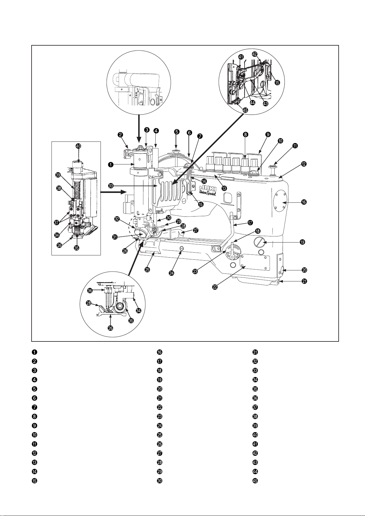
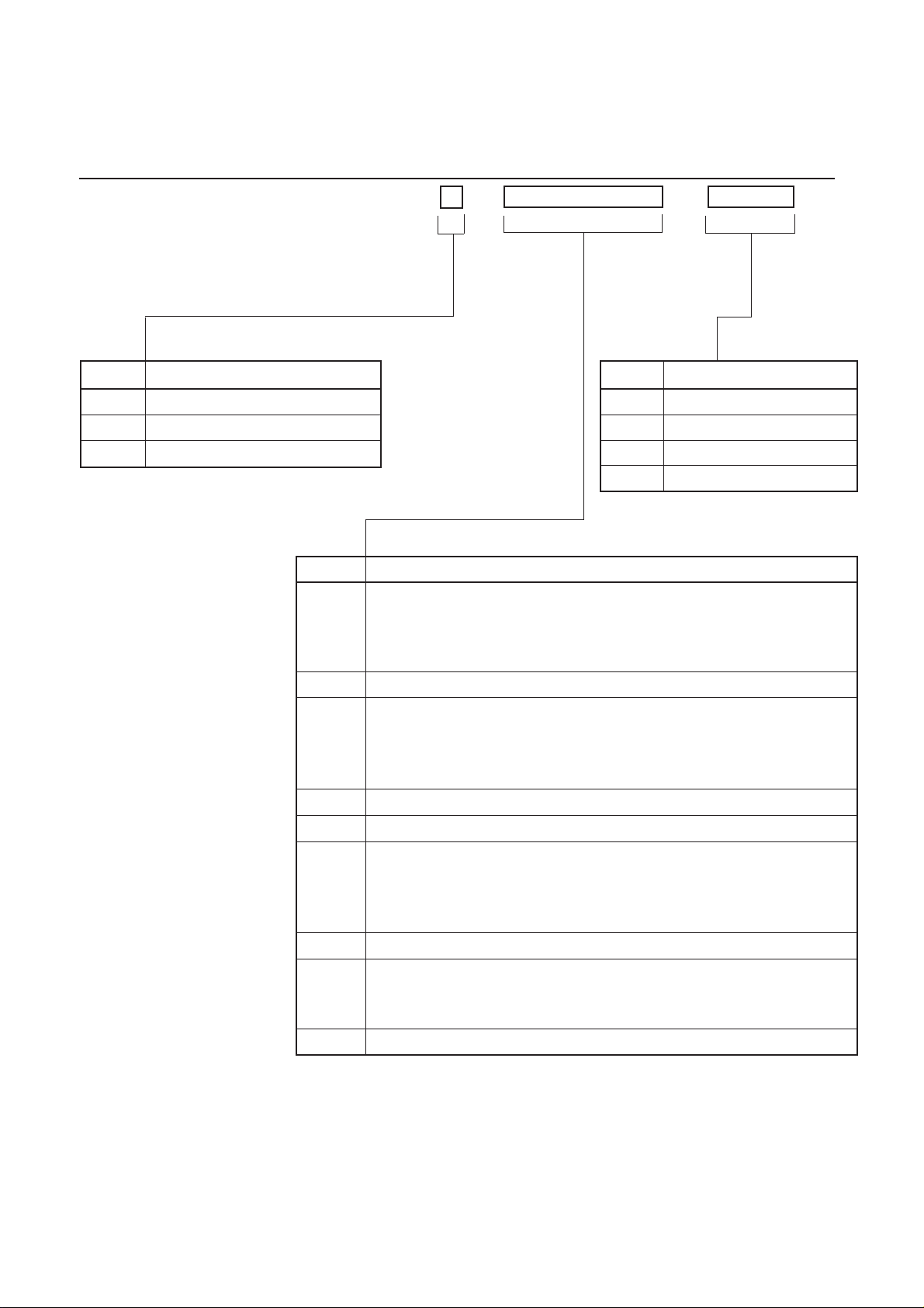
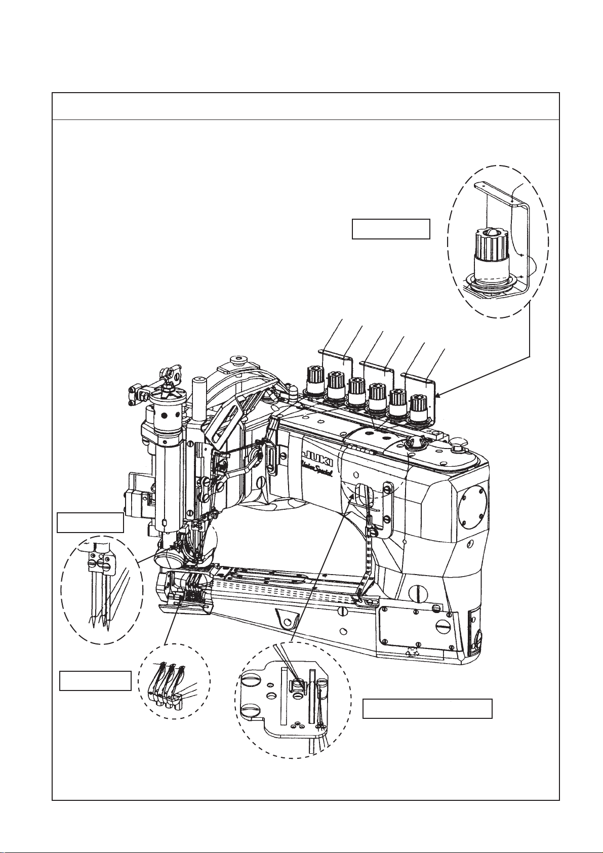
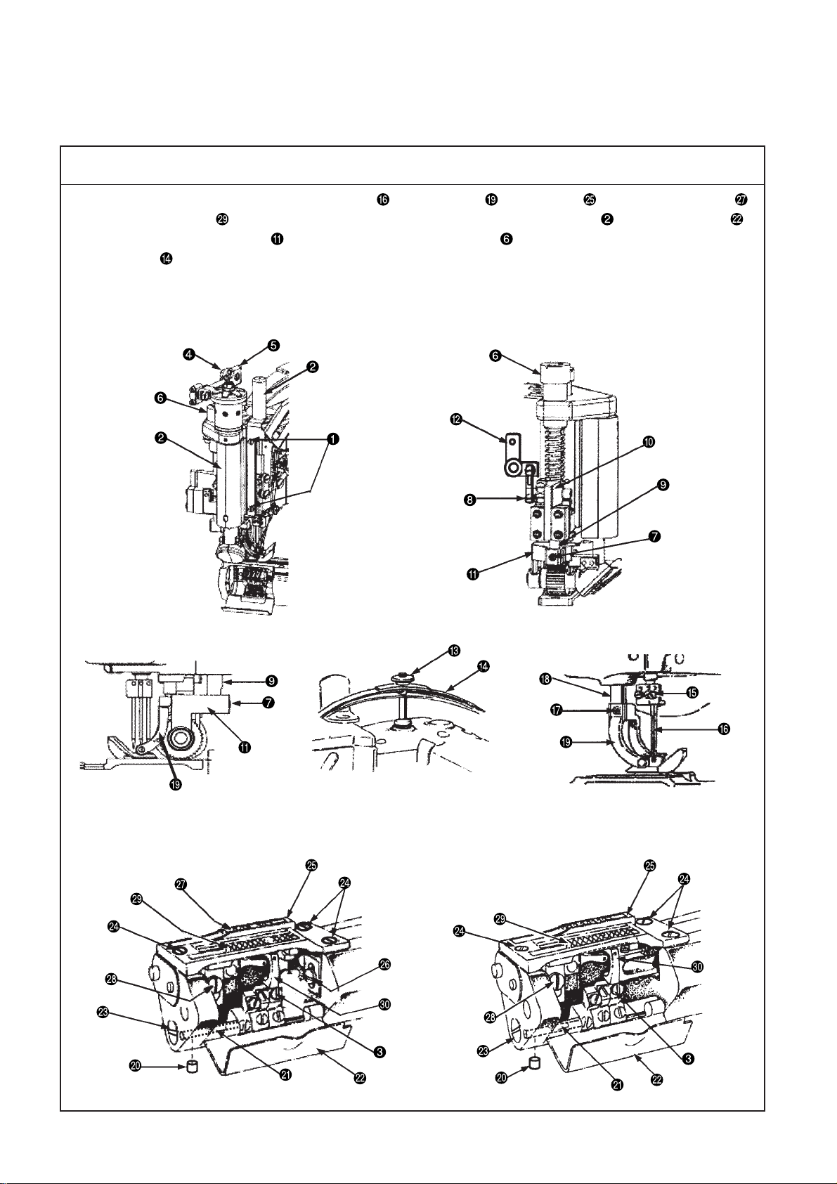
5. Names of machine head
Belt drive upper
feed roller
Clutch drive upper feed roller End cover Gear cover (front)
Clutch rod Bobbin thread guide pipe Gear cover (rear)
Clutch lever Differential regulation lever Swing guard
Cover for needle bar and roller
Pressure regulating nut Oil gauge (front) Upper feed roller
Pressure regulating plate spring assembly Oil discharge screw (front) Needle clamp
Oil circulation inspection window (rear) Cylinder side cover Right and left guide plates
Thread tension knob Gauge plate Guide finger
Thread guide Feed rocking lever eccentric pin
Oil circulation inspection window (front) Looper cover
Looper push button Throat plate
Front top cover Three folding device Rocking balance thread guide
Rear top cover Presser Needle thread rocking balance
Needle thread guide path
Needle thread adjusting path Needle bar Needle thread small tensioner
Window screw for stitch length adjustment
Needle guard & needle cooling pipe
Upper feed roller assembly
Roller pressure regulating spring
Roller pressure regulating screw
Needle thread lever-thread guide
Needle thread support adjuster
– 7 –
Page 12
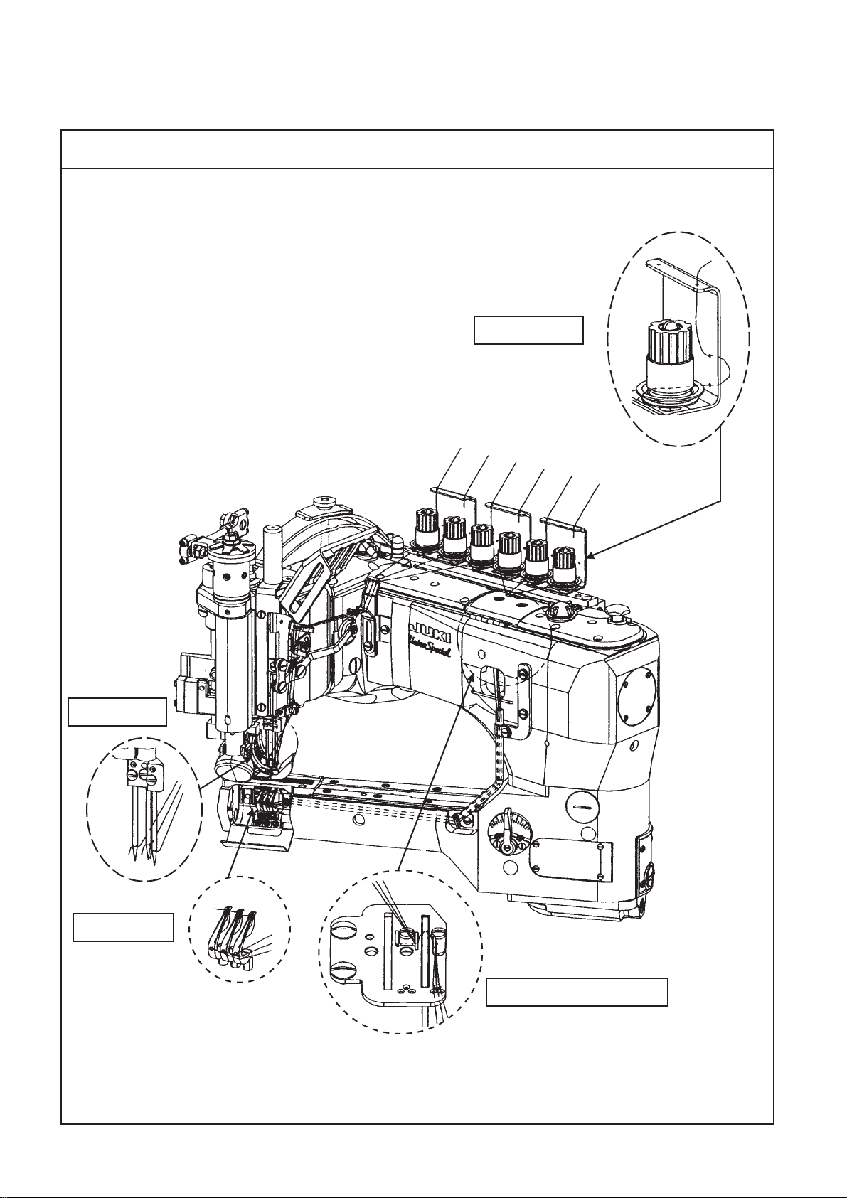
6. How to pass the threads
(1) Differential feed
How to pass the needle threads and looper threads
1. Drawing of differential feed threading (sample model: 35800DNU & BWDN)
Needle thread: 1 for left needle thread, 2 for middle needle thread, 3 for right needle thread
Looper: 4 for front looper, 5 for middle looper, 6 for rear looper
Follow the drawing below to pass the threads.
Tension section
[Model: 35800DNU]
Needle section
1
2
3
4
5
6
3
2
1
Looper section
5
4
6
Looper thread cam section
– 8 –
Page 13
(2) 1 piece feed
How to pass the needle threads and looper threads
1. Drawing of 1 piece feed threading (sample model: 35800DRU & BWDR)
Needle thread: 1 for left needle thread, 2 for middle needle thread, 3 for right needle
thread
Looper: 4 for front looper, 5 for middle looper, 6 for rear looper
Follow the drawing below to pass the threads.
Tension section
[Model: 35800DRU]
Needle section
1
2
3
4
5
6
3
2
1
Looper section
5
4
6
Looper thread cam section
– 9 –
Page 14
7. Standard adjustment
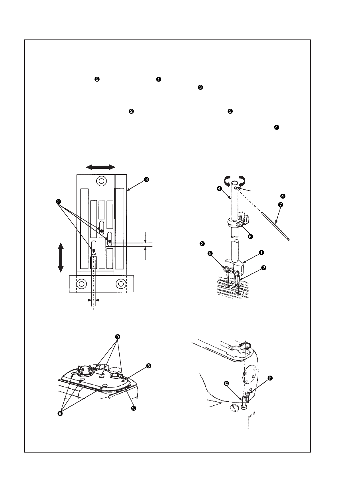
(1) How to remove the gauge components and upper feed roller (differential feed
mechanism and 1 piece feed mechanism)
Disassembly procedure
1. Remove the gauge, its related parts (needle , presser yoke , throat plate , differential feed dog ,
and main feed dog ), the cover, its related parts (cover for needle bar and roller and looper cover ),
upper feed roller assembly , roller pressure regulating screw , and pressure regulating plate spring
assembly before adjustment.
(Caution) The directions of front, rear, right, and left during standard adjustment are based on the operator
working position. Therefore, the forward rotation of the pulley is counterclockwise.
Left side of the machine head
Right side of the machine head
Rear side of the machine head
Pressure regulating plate spring
and its related parts
Left side of the machine head
Gauge and its related parts
(Differential feed mechanism)
Gauge and its related parts
(1 piece feed mechanism)
– 10 –
Page 15
Disassembly procedure
Removal procedure of the gauge and upper feed roller
1. Loosen the setscrew and remove the needle bar and the roller cover together with the face cover and
the packing, which are attached to the rear side.
2. Loosen the nut with a 3/8” spanner and remove the washer and clutch rod .
3. Remove the roller pressure regulating screw .
4. Loosen the setscrew securing the upper feed roller shaft with a 3/32" key wrench, remove the setscrew
securing the link, lift the upper feed roller shaft and the guide finger , and remove the upper feed
roller assembly .
(Caution) When the upper feed roller shaft is lifted, the guide finger interferes with the lift lever
crank . Therefore, remove the upper feed roller assembly after lifting the lift lever crank
slightly.
5. Loosen the pressure regulating nut and remove the pressure regulating plate spring assembly .
6. Loosen each setscrew that securing corresponding needles and remove three of each needle .
7. Loosen the setscrew securing the presser yoke with a 5/64" or 2mm key wrench and remove the
presser yoke after lifting the presser shaft .
8. Loosen the setscrew with a 3/32" key wrench and remove the setscrew securing the cover.
Removal of the setscrew allows you to remove the looper cover and spring stud .
9. Loosen three setscrews securing the throat plate and remove the throat plate .
10. Loosen the setscrew and remove the differential feed dog .
11. Loosen the setscrew and remove the main feed dog .
12. Loosen the setscrews securing the loopers and remove the loopers .
(Caution) The disassembly procedure mentioned above mainly describes about the differential feed
mechanism.
As to the 1 piece feed mechanism, the differential feed dog and setscrew are not
provided.
– 11 –
Page 16
(2) Timing between the looper and needle bar
Standard Adjustment
1. Timing between the looper and needle bar (synchronization)
Gauging equipment is mounted to perform synchronization adjustment.
The reference state is that there is no clearance between the bottom surface of the lower needle bar bushing
and the top surface of the timing gauge when the steel rod touches the throat plate by rotating
the pulley in the forward and backward directions. (Be sure to rotate the pulley in both directions to check the
clearance.) The allowable clearance range is from 0 to 0.1 mm.
(Caution) The allowable clearance between the steel rod and the throat plate ranges from 0 to 0.1
mm when the bottom surface of the lower needle bar bushing touches the top surface of
the timing gauge ahead of the other touch by rotating the pulley in both directions.
Right-left direction
Clearance at rotation in both
directions: 0 to 0.1 mm
19mm
Touch between the steel rod
and throad plate
Match mark
Clockwise-counterclockwise
direction
– 12 –
Page 17
Adjustment Procedures Results of Improper Adjustment
1. How to install and use the synchronization adjustment gauge
(1) Put the steel rod in the front looper base and tighten the
setscrew .
(Caution) Use a key wrench (3 mm) instead of the steel rod if
necessary.
(2) Loosen the setscrew slightly and move the front looper base
with the steel rod integrated to the most left position.
(3) Install the throat plate and tighten the setscrew .
(4) Rotate the pulley to move the steel rod to the most left position,
set the clearance between the right surface of the steel rod and the
left surface of the throat plate to 19 mm, and tighten the setscrew
securing the front looper base .
(5) Rotate the pulley counterclockwise and stop it when the steel rod
touches the left surface of the throat plate .
(6) Mount the timing gauge to the needle bar . Be sure to mount
the timing gauge so that the top surface of the timing gauge
touches the bottom surface of the lower needle bar bushing .
(Caution) Use a clip instead of the timing gauge if necessary.
(7) When the pulley is rotated clockwise, the steel rod moves from
side to side.
Touch the steel rod with the left surface of the throat plate again.At
this moment, make sure that the clearance between the bottom
surface of the lower needle bar bushing and the top surface of
the timing gauge is within the allowable range.
(Caution) The bottom surface of the lower needle bar bushing
may touch the top surface of the timing gauge ahead
of the other touch. In such a case, make sure that the
clearance between the steel rod and the throat plate
is within the allowable range.
(8) If the timing between the looper (steel rod ) and the needle bar
is inappropriate, follow the procedure below.
oImproper synchronization position
adjustment may cause stitch
skipping or thread breakage.
2. Corrective points and corrective measures
(1) For adjusting the timing between the looper (steel rod ) and the
needle bar , loosen 9 setscrews securing the rear top cover
and remove the rear top cover and the packing.
(2) Loosen 3 fixing nuts securing the front and rear main shaft
couplings ( and ) and engage a key wrench (3/32") with the
setscrew to move the front main shaft coupling in the clockwise-
counterclockwise direction for adjustment while keeping the rear
main shaft coupling unmoved. (For the fixing nut , use a 1/4"
spanner.)
(Caution) 1. Align the match marks.
2. For moving the front main shaft coupling ,
temporarily tighten one of the fixing nuts , which
is close to the match mark, and make an adjustment.
oTo increase the clearance between the steel rod and throat plate
, rotate the front main shaft coupling clockwise.
oTo decrease the clearance between the steel rod and throat plate
, rotate the front main shaft coupling counterclockwise.
(3) After adjustment, put the rear top cover and packing back on
and tighten the setscrew .
– 13 –
Page 18
(3) Adjustment of the needle entry positions in the right-left and front-rear directions
Standard Adjustment
1. Needle entry
1) Needle entry position in the right-left direction
Mount 3 needles to the needle clamp . The standard needle entry position "A" in the right-left
direction is the center of the needle hole of the throat plate .
2) Needle entry position in the front-rear direction
The standard needle entry position in the front-rear direction is decided under the condition that the
clearance between the needle and needle hole of the throat plate , "B", is the same for all of 3
positions.
(Caution) Adjust the needle entry position in accordance with the temporary needle bar height of
12.5 mm.
Refer to "(5) Adjustment of the needle bar height".
Right-left direction
Clockwise-counterclockwise direction
Hole at the top of the
needle bar
Front-rear
direction
B
Same in 3 needles
A
Center
Clockwise-counterclockwise direction
– 14 –
Page 19
Adjustment Procedures Results of Improper Adjustment
1. Checking procedure of needle entry
(1) Mount 3 needles to the needle clamp and tighten the setscrew
.
(2) Loosen the needle bar holding screw , set the temporary needle
bar height (12.5 mm), and tighten the needle bar holding screw
{6} temporarily (approximately 4 turns of the needle bar ).
(3) Insert the torque rod into the hole at the top of the needle bar
and rotate the needle bar in the right-left direction to adjust the
needle entry position in the front-rear and right-left directions.
(Caution) 1. When the needle position is not in the center of
the needle hole of the throat plate in the right-left
direction, follow the procedure below.
2. For needle entry adjustment, mount the rear needle
guides temporarily and make sure that 3 needles
touch evenly.
2. Needle entry adjustment
(1) For adjusting the needle entry position in the right-left direction,
remove 6 setscrews securing the front top cover to remove
the front top cover and packing .
(2) Loosen the hexagon head bolt , engage a driver with the eccentric
pin , and rotate the driver in the right-left direction. Then, the
sylinder arm moves in the right-left direction.
(3) Adjust the needle entry position in the right-left direction.
o Rotation of the eccentric pin clockwise moves the cylinder arm
leftward.
o Rotation of the eccentric pin counterclockwise moves the cylinder
arm rightward.
(4) After adjustments, tighten the hexagon head bolt .
(5) After adjusting the needle entry position, put the front top cover
and packing back on and tighten the setscrew .
o Improper needle entry position
adjustment may cause stitch
skipping, needle breakage, or
thread breakage.
– 15 –
Page 20

(4) Looper adjustment
Standard Adjustment
1) Looper return
When each looper ( , , and ) is at the most left position, the standard distance from the tip of each
looper ( , , and ) to the center of each needle ( , , and ) is 3.6 mm (9/64").
1. Standardization of the front looper
When the front looper is at the most left position, measure the distance from the tip of the front looper
to the center of the left needle with the gauge and a scale and adjust the distance to the
standard value, i.e. 3.6 mm (9/64").
2. Standardization of middle and rear loopers
When the tips of the middle and rear loopers ( and ) are simultaneously aligned with each left
surface of the middle and right needles as well as the tip of the front looper with the left surface of the
left needle , the middle and rear loopers are in the standard positions.
(Caution) For the front looper , the looper return is adjusted with the gauge and a scale, and for
the middle and rear loopers ( and ), the looper return is adjusted by aligning the tips
of the middle and rear loopers ( and ) with the left surfaces of the needles ( and ),
respectively.
Alignment
Alignment
Front-rear direction
Right-left direction
3.6mm
9/64
2) Adjustment of the clearance between the looper and needle
When the tips of each looper ( , , and ) are at the center of each needle ( , , and ), the standard
clearance is 0.0mm (slight touch).
After adjusting the rear needle guide , make sure again that the clearance between the loopers ( , ,
and ) and the needles ( , , and ) is 0.0 mm respectively, and perform final adjustment of the clearance
after threading.
(Caution) If clearance adjustment is performed without the rear needle guide , a little strongly touch
the tips of the loopers ( , , and ) with the needles ( , , and ), respectively.
Center of needle
• •
• •
Front-rear direction
Clearance of
0.0 mm
(slight touch)
Looper tip
Clearance of 0.0 mm (slight touch)
– 16 –
Page 21

Adjustment Procedures Results of Improper Adjustment
1) Looper return
(1) Front looper
1. Loosen the setscrews to remove the throat plate .
2. Mount the front looper on the front looper base and tighten
the setscrew .
3. Rotate the pulley counterclockwise, move the front looper to
the most left position, and measure the clearance from the tip of
the front looper to the left needle with the looper gauge
or a scale.
4. For adjusting the clearance to the standard distance, loosen the
setscrew securing the front looper base to adjust the position
of the front looper base in the right-left direction.
5. After adjustment, tighten the setscrew to secure the front looper
base setscrew .
(2) Middle looper
1. Rotate the pulley counterclockwise and align the tip of the front
looper with the left surface of the left needle .
2. Mount the middle looper on the middle looper base and
tighten the setscrew .
3. Loosen the setscrew securing the middle looper base and
move the middle looper base in the right-left direction to align
the tip of the middle looper with the left surface of the right
needle .
4. After adjustment, tighten the setscrew to secure the middle
looper base.
(3) Rear looper
1. Rotate the pulley counterclockwise and align the tip of the front
looper with the left surface of the left needle .
2. Mount the rear looper on the rear looper base and tighten
the setscrew .
3. Loosen the setscrew securing the rear looper base and move
the rear looper base in the right-left direction to align the tip of
the rear looper with the left surface of the middle needle .
4. After adjustment, tighten the setscrew to secure the rear looper
base.
(Caution) When the positions of each looper base ( , , and )
are adjusted in the right-left direction, adjust the
clearances from the tips of the loopers ( , , and )
to the needles ( , , and ) as well.
o Insufficient or excessive looper
return may cause stitch skipping,
needle breakage, or thread
breakage.
2) Adjustment of the clearance between the looper and needle
1. Loosen the setscrews ( , , and ) securing the looper bases
to adjust the positions of the looper bases ( , , and ) in the
front-rear direction.
2. After adjustments, tighten the setscrews ( , , and ) to secure
the looper bases.
(Caution) When the clearances are adjusted, check the looper
return positions for each looper ( , , and ) in the
right-left direction because the looper bases ( , , and
) may move in the right-left direction.
– 17 –
o When each looper base ( , ,
and ) is moved leftward, each
tip of loopers ( , , and ) is
detached from each needle ( ,
, and ).
o When each looper base ( , ,
and ) is moved rightward, each
tip of loopers ( , , and )
touches each needle ( , , and
).
Page 22

(5) Adjusting the height of the needle bar
Standard Adjustment
1. Height of the needle bar
(1) Alignment between the bottom surface of the front looper and the top hole end of the left needle
When the pulley is rotated counterclockwise and the bottom surface of the front looper is aligned with
the top hole end of the left needle
distance from the tip of the front looper
(2) Alignment between the tip of the front looper and the left surface of the left needle
When the pulley is rotated counterclockwise and the tip of the front looper is aligned with the left
surface of the left needle , the standard needle bar height is achieved by adjusting the distance from
the bottom surface of the front looper to the top hole end of the left needle to 1.6 mm.
(Caution) For adjusting the needle bar height, select an easier-to-adjust one from either (1) or (2)
mentioned above.
(3) Checking of the middle and rear looper heights shall be also checking of each looper return.
(Caution) 1. Needle entry adjustment is performed in accordance with the temporary needle bar
height.
When the needle bar is at the upper dead point, the temporary clearance between the
top surface of the throat plate and the tips of the needles is 12.5 mm.
2. The needle bar height is temporarily adjusted for needle enty adjustment. If there is no
problem with the needle bar height, readjustment of the needle bar height is not required.
Advance to the next step.
, the standard needle bar height is achieved by adjusting the
to the right surface of the left needle to 0.8 mm.
Alignment between the bottom surface of the
looper and the top hole end of the needle
Right surface of
the left needle
Temporary needle bar height
Alignment
0.8 mm
Alignment between the tip of the looper and the
right surface of the needle
Right surface of
the left needle
Alignment
1.6 mm
12.5mm
Top surface of the throat plate
– 18 –
Page 23

Adjustment Procedures Results of Improper Adjustment
1. Adjustment of the needle bar height
(1) Remove the needle bar, roller cover, surface cover, and packing.
(2) Loosen the setscrew and adjust the needle bar position
vertically.
(3) After adjustment, tighten the setscrew .
(Caution) Use cau tio n not to ro tate the needle bar at adjustment
of needle bar height.
Failure to observe this changes needle entry positions.
o Remarkably improper needle bar
height adjustment may cause
stitch skipping, needle breakage,
or thread breakage.
– 19 –
Page 24

(6) Adjustment of the looper motion paths
Standard Adjustment
1. Looper momentum in the front-rear direction
(1) The standard position of the front looper is decided under the condition that the tip of the needle
touches the rear of the front looper at 1/4" from the bottom surface when the pulley is rotated
counterclockwise and the front looper is moved from right to left after mounting the front looper in a
standard manner.
(2) For the middle and rear loopers ( and ), the standard position for each is decided under the same
condition as the front looper, i.e. the tips of the needles ( and ) touch the rear of the loopers at 1/4" from
the bottom surfaces, respectively.
(Caution) If the material has a thick unevenness during sewing, contact areas between the needle tips
and the rear surfaces of the loopers ( and ) may become smaller. (to prevent needle tip
breakage)
• •
Right-left direction
• •
1/4" from the
bottom surface
Differential feed model
Model: 35800DNU
Up-down direction
1 piece feed model
Model: 35800DRU
Up-down direction
– 20 –
Page 25

Adjustment Procedures Results of Improper Adjustment
1. Adjustment of longitudinal movement of differential feed looper
(1) Loosen the setscrews (4 pcs.) and remove the cylinder side cover
.
(2) Loosen the setscrew of the ball joint with a spanner wrench
(TT85), and adjust the the forward/reverse movement by moving
the setscrew forward or backward.
(3) After adjustments, mount the cylinder side cover , and tighten the
setscrews .
2. Adjustment of longitudinal movement of 1 piece feed looper
(1) Loosen the setscrews (4 pcs.) and remove the cylinder side cover
.
(2) Loosen the setscrew of the ball joint with a screwdriver, and
adjust the the forward/reverse movement by moving the setscrew
forward or backward.
(3) After adjustments, mount the cylinder side cover , and tighten the
setscrews .
o When reducing the front and rear momentum amount of the looper,
move the ball joints and upwards.
o When increasing the front and rear momentum amount of the looper ,
move the ball joints and downwards.
(Caution) 1. When the front and rear momentum amount of the
looper has been adjusted, move the respective looper
bases , , and and readjust the front/rear
positions of the needles ( , , and ) and the
loopers ( , , and ).
2. When the above-mentioned adjustments are carried
out, the throat plate should be removed.
o When the front and rear momentum
amount of the looper is small:
The amount of contact becomes
large between tips of the needles
( , , and ) and rear parts of
the loopers ( , , and ) and
this can be a cause of needle tip
being blunt.
o When the front and rear momentum
amount of the looper is large:
The clearance becomes large
between tips of the needles ( ,
, and ) and rear parts of the
loopers ( , , and ) and this
can be a cause of stitch skipping.
– 21 –
Page 26

(7) Adjustment of rear needle guide
Standard Adjustment
1) Longitudinal adjustment of the rear needle guide
1. When the pulley is turned counterclockwise and the rear needle holder advances to the most front
position, it lightly touches the left needle and then tip of the front looper passes.
When tip of the front looper reaches the position 1.5mm apart from the left side of the left needle
while this front looper moves in right direction, the standard position is that the needle tip comes in
contact with the rear needle holder .
2. The relationship between the middle needle and the rear looper and between the right needle and
the middle looper is also required to assume the same conditions as 1. above in standard positioning.
(Caution) 1. The rear needle holder somewhat changes its contact position with the respective
needles ( , , and ) according to the needle entry position.
Recheck the needle entry condition for adjustments if the contact positions of the right
and left needles ( and ) seem to be different.
2. To change the stitch length, readjustment of the front and rear positions is also needed
for the rear needle holder .
2) Height adjustment of rear needle guide
1. When tip of the front looper coincides with the right side of the left needle , the standard dimension is
2.0mm between the lower position "A" of the needle hole and Point B of the rear looper .
2. The relationship between the middle needle and the rear looper and between the right needle and
the middle looper is also required to assume the same conditions as 1. above in standard positioning.
Longitudinal directions of rear needle guide
1.5mm
Longitudinal directions
• •
• •
Vertical direction of rear needle guide
Right and left directions
A
B
2.0mm
The clearance between tip of looper
and needle is 0.0 mm.
(Light contact)
– 22 –
Page 27

Adjustment Procedures Results of Improper Adjustment
1) Longitudinal adjustment of the rear needle guide
1. Loosen the setscrew and move the rear needle guide forward
or backward to adjust the height.
2. After adjustments, tighten the setscrew .
(Caution) When the rear needle holder is adjusted, recheck the
presence of a clearance between the respective needles
( , , and ) and the respective loopers ( , , and
). If any clearance is perceived, readjust the related
conditions.
2) Height adjustment of rear needle guide
1. Loosen the setscrew and move the rear needle guide base
vertically to adjust the height.
2. After adjustments, tighten the setscrew .
o If a clearance is actually
developed between the needles
, , and the rear needle
holder , this can be a cause of
needle breakage or stitch
skipping.
o When the rear needle holder
presses the respective needles
( , , and ) too much, this can
be a cause of needle tip being
blunt.
– 23 –
Page 28

(8) Adjustment of feed dog height and longitudinal movement (differential feed dog mechanism)
Standard Adjustment
1) Height of main feed dog
The standard height is defined when the main feed dog attains the highest level and the root section of
the main feed dog coincides with the upper face of the main feed dog throat plate .
2) Height of differential feed dog
The standard height of the differential feed dog is defined when the main feed dog attains the highest
level and a clearance of 0.05 to 0.1mm is secured between the upper face "A" of the main feed dog and
the bottom face "B" of the differential feed dog .
3) Adjustment of longitudinal movement of main feed dog
The maximum amount of feed of the main feed dog is 3.6 mm. (Standard: 3.2 mm)
When the main feed dog attains its maximum feeding amount, the standard positioning is secured when
Clearance "C" and Clearance "D" are equalized. Clearance "C" is defined as the distance from the feed
groove front section of the throat plate to the front section of the main feed dog in position where the
main feed dog stays in the most advanced position. Clearance "D" is defined as the distance from the
feed groove rear section of the throat plate to the rear section of the main feed dog {1} in position where
the main feed dog has attained the most retreated position.
4) Adjsutment of vertical height of main feed dog and differential feed dog
For the feed rocking lever eccentric pin of the feed dog, the standard positioning of the driver groove is
horizontal.
The vertical height of the main and differential feed dogs ( and ) can be simultaneously adjusted by
turning the feed rocking lever eccentric pin . Basically, however, this function should be used in standard
position.
5) Gradient of main feed dog and differential feed dog
Front lowering condition is standard.
Height of main feed dog
Top surface
0.05 to 0.1mm
Height of differential feed dog
B
A
Coincidence
Clearance of the main feed dog
in the most advanced position
C
Clearance of the main feed dog in
the most retreated position
Longitudinal
directions
D
Driver groove
– 24 –
Page 29

Adjustment Procedures Results of Improper Adjustment
Adjustment of main feed dog and differential feed dog
1. For the feed rocking lever eccentric pin of the feed dog, the
standard positioning of the driver groove is horizontal.
If the driver groove seems to be inclined deviating from the standard
positioning, loosen the setscrew and adjust the feed rocking lever
eccentric pin of the feed dog until it assumes its horizontal posture.
Since then, tighten the setscrew .
2. Mount the main feed dog , differential feed dog and throat
plate , and fix the throat plate .
3. In the first place, adjust the height of the main feed dog to the
standard position. Then fix it by tightening the setscrew .
4. Apply the feed dog support to the bottom of the front section of
the main feed dog and tighten the setscrew .
5. Then, adjust the height of the differential feed dog to the standard
position. After that, fix it by tightening the setscrew .
6. According to "(10) Feed adjustments, 1) Adjustment of stitch length",
adjust the maximum feed amount of the main feed dog to 3.6mm.
(Apply a ruler to the side of the main feed dog and confirm the
result by turning the pulley counterclockwise.)
7. Turn the pulley counterclockwise and confirm that there is no contact
between the main feed dog and the feed groove front/rear section
of the throat plate .
If there is any contact, loosen the setscrew of the main feed
rocking lever link and turn the main feed rocking eccentric drive
stud to adjust the throat plate not to contact the feed groove
front/rear section. After adjustments, tighten the setscrew .
8. After the front and rear momentum amount has been adjusted for
the main feed dog , adjust the sewing length to the standard value
of 3.2mm.
(Caution) 1. In t he cas e of fr ont and re ar a dju stments of the
differential feed dog mechanism, specific attention
should be paid to the fine feed dog section of the
main feed dog .
2. To make front and rear adjustments of the main feed
dog , loosen eight setscrews of the cylinder
cover and remove the cylinder cover set .
After adjustments, mount the cylinder cover set ,
and tighten the setscrews .
3. For the main feed dog and the differential feed
dog , the longitudinal gradients and the
horizontality are kept constant and cannot be
adjusted.
When the height of feed dogs ,
is insufficient
o The amount of feed is decreased
and uneven feeding can occur.
oWhen the height of the rear
needle guide is lowered, this will
cause breakage of a needle or
stitch skipping.
When the height of feed dogs ,
is excessive
o This can be a cause of the
materials pushed back to the front
side, or of giving rise to feed flaws.
oWhen the height of the rear
needle holder is raised and the
margin of the needle contact
position is increased, this will
cause failure in producing loops
and stitch skipping.
– 25 –
Page 30

(9) Adjustment of feed dog height and longitudinal movement (1 piece feed dog mechanism)
Standard Adjustment
1) Height of main feed dog
The standard height is defined when the main feed dog
of the main feed dog
coincides with the upper face of the throat plate of the main feed dog .
2) Adjustment of longitudinal movement of main feed dog
The maximum amount of feed of the main feed dog is 3.6 mm. (Standard: 3.2 mm)
When the main feed dog attains its maximum feeding amount, the standard positioning is secured when
Clearance "A" and Clearance "B" are equalized. Clearance "A" is defined as the distance from the feed
groove front section of the throat plate to the front section of the main feed dog iin position where the
main feed dog stays in the most advanced position. Clearance "B" is defined as the distance from the
feed groove rear section of the throat plate to the rear section of the main feed dog in position where
the main feed dog has attained the most retreated position. (A = B)
Height of main feed dog
attains the highest level and the rear root section
Clearance of the main feed dog
in the most advanced position
Coincidence
A
B
Clearance of the main feed dog
in the most retreated position
– 26 –
Page 31

Adjustment Procedures Results of Improper Adjustment
1) Height of main feed dog
1. Apply the rear support screw to the bottom right of the main feed
dog , tighten the setscrew , and mount the throat plate .
2. Check the standard height of the main feed dog.
o If the main feed dog is low, raise the rear support screw .
o If the main feed dog is high, raise the rear support screw .
3. Remove the throat plate , loosen the setscrew to remove the
main feed dog , and adjust height of the front support screw .
4. After adjustments, mount the main feed dog , tighten the setscrew
, mount the throat plate , and tighten the setscrew .
2) Adjustment of longitudinal movement of main feed dog
1. Loosen the setscrews ( and ) and remove the plug female screw
.
2. Using a screwdriver, turn the eccentric pin clockwise and
counterclockwise until the front and rear positions of the main feed
dog are properly adjusted.
When the height of main feed dog
is insufficient
o The amount of feed is decreased
and uneven feeding can occur.
oWhen the height of the rear
needle guide is lowered, this will
cause breakage of a needle or
stitch skipping.
When the height of main feed dog
is excessive
o This can be a cause of the
materials pushed back to the front
side, or of giving rise to feed flaws.
oWhen the height of the rear
needle holder is raised and the
margin of the needle contact
position is increased, this will
cause failure in producing loops
and stitch skipping.
– 27 –
Page 32

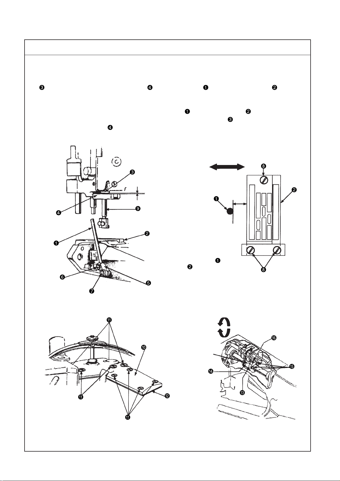
(10) Adjustment of feed mechanisms
Standard Adjustment
1) Adjustment of stitch length (standard: 8 stitches/inch interval)
The stitch length can be adjusted within the range of 2.1 mm to 3.6 mm. Standard adjustment is 3.2 mm.
For the adjustment of the stitch length, loosen the lever setscrew and move the lever upwards or
downwards until the required length is secured.
(Caution) If the stitch length has been changed, check "(7) Adjustment of rear needle guide" and
make a proper readjustment.
Vertical direction
2) Adjustment of differential feed amount
The amount of differential feed can be adjusted by moving the differential adjusting lever forward or
backward.
The graduation plate is provided with the engraved numbers of 1 to 9. Numbers 1 to 4 denote differential
motion, Number 5 denotes no differential motion, and 6 to 9 denote forward differential.
(Caution) No differential function is provided to the single feed mechanism.
Longitudinal directions
1
9
– 28 –
Page 33

Adjustment Procedures Results of Improper Adjustment
1) Stitch length adjustment
1. When the stitch length adjusting window screw is removed, the
lever setscrew can be seen.
o Loosen the lever setscrew to move the lever upwards and fasten
the lever setscrew there. This action increases the stitch length.
o Loosen the lever setscrew to move the lever downwards and
fasten the lever setscrew there. This action decreases the stitch
length.
(Caution) No graduation is available for the adjustment of the
stitch length.
2) Adjustment of differential feed amount
o When the differential adjusting lever is advanced in the reverse
differential direction (1 to 4), the differential ratio is decreased and
the sewed materials are extended.
o When the differential adjusting lever is retreated in the forward
differential direction (6 to 9), the differential ratio is increased and
the sewed materials are shrunk.
* When fixing the differential adjusting lever , pinch it with two
setscrews and .
When the stitch length is changed
o If the forward or backward
movement of the main feed dog
is changed, the contact amount is
also changed between each
needle and the rear needle holder.
Since this can be a cause of stitch
skipping, the rear needle holder
should be readjusted.
– 29 –
Page 34

(11) Presser adjustment
Standard Adjustment
1) Adjustment of amount of rise of presser
The standard amount of rise is 6.5mm for the standard class of the presser
9 mm)
In standard positioning, the presser
begins to rise faster by 3.2mm above the upper face of the throat
plate before the upper feed roller begins to rise.
(Caution) 35800BWW-DWW: The maximum amount of rise is 10mm for extra-heavy materials.
2) Adjustment of presser bar pressure
Proper pressure of the presser shall be applied to the material while it is sewn.
Turn the pressure adjusting nut clockwise and counterclockwise to adjust pressure.
. (Maximum amount of rise:
6.5mm
6.5mm
C
D
0.8mm
A
B
1.6mm
– 30 –
Right direction
Page 35

Adjustment Procedures Results of Improper Adjustment
1. Installation and pressure adjustment of presser and presser yoke
(1) Raise the presser shaft , mount the presser yoke on the presser
shaft , and tighten the setscrew .
(2) Confirm whether the presser shaft smoothly moves up and down,
being free from rattling on the right and left.
If there is rattling on the right and left, loosen four setscrews to
set up the presser shaft guide to eliminate right and left rattling
by means of the right/left holding guide plate . Make adjustments
to permit the presser shaft to perform light movement up and down.
Since then, tighten the setscrew .
(3) Install the pressure adjusting leaf spring set and turn the pressure
adjusting nut until pressure of the presser is duly adjusted.
oTurning the pressure adjusting nut clockwise causes the pressure
to increase.
0Turning the pressure adjusting nut counterclockwise causes the
pressure to decrease.
(4) In order to make the presser rise by 3.2mm faster than the upper
feed roller, loosen the setscrew of the presser shaft guide
and move the presser shaft guide up and down until a clearance
of 0.8mm is secured between the lower hole face of the lever link
and the bottom face of the lever link hanger setscrew . (Lower
dead point of the needle bar)
(Caution) When the above-mentioned adjustments are made, the
connecting positions shall be secured for the lifter lever
with slide hole and the lifter lever by moving the
lifter lever with slide hole in the right direction. When
proper positioning has been secured, tighten the
setscrew .
(5) To secure the standard amount of rise of 6.5mm for the presser ,
loosen the setscrew and move the stop collar up and down
until a clearance of 6.5mm is secured between the lower face "C" of
the mounting position of the presser shaft guide bush and the
upper face "D" of the stop collar . Since then, tighten the setscrew
.
(Caution) At the same time, check the mounting position of the
needle thread rocking thread take-up bar connecting
base .
At the lower dead point of the needle bar, a clearance of
1.6mm shall be secured between the bottom face A of
the needle thread rocking thread take-up bar connecting
base and the upper face B of the cut section of the
front cover .
o If the amount of presser rise is too
excessive than required, the
presser will touch the needle
clamp, thus causing needle
breakage or stitch skipping.
o If pressure of the presser is too
insufficient or excessive than
required, the material cloth will
advance awkwardly.
2. Removal and installation of presser only
(1) To replace presser only, loosen the right and left setscrews
and change the presser .
Then, tighten the right and left setscrews .
– 31 –
Page 36

(12) Adjustment of upper feed roller
Standard Adjustment
1. Adjustment of upper feed roller
(1) The standard clearance is 0.08mm minimum to 0.13mm maximum between the lower position of the
upper feed roller
(2) The standard front/rear and right/left clearances shall be uniform between the upper feed roller
the feed dog .
(3) The standard positioning of the upper feed roller shall be free from right and left rattling, permitting
smooth movement up and down.
and the upper face of the throat plate .
Unified right and left
clearances
0.08mm to 0.13mm
and
Standard clearance
toward the throat plate
Vertical direction
Frame shaft hole of the
upper feed roller
Right and left directions
– 32 –
Page 37

Adjustment Procedures Results of Improper Adjustment
1. Installation of upper feed roller
(1) Raise the upper feed roller pressing shaft and insert the upper
feed roller pressing shaft in the frame shaft hole of the upper
feed roller frame set . Then, tighten the setscrew .
Simultaneously at that time, insert the lever connecting section
in between the roller connecting section to join it.
(2) Install the roller pressure adjusting screw .
(3) Confirm that a standard clearance (Clearance gauge: 0.08mm to
0.13mm) is secured between the upper feed roller and the upper
face of the throat plate .
(4) Confirm that there is proper pressure at the upper feed roller ,
enough to feed the material cloth.
c Pressure adjustment
oTurning the roller pressure adjusting screw clockwise causes the
pressure to increase.
oTurning the roller pressure adjusting screw counterclockwise
causes the pressure to decrease.
(Caution) Confirm that the upper feed roller pressing shaft can
be raised by both hands when installing the roller
pressure adjusting screw .
2. Clearance adjustment between upper feed roller and throat plate
(1) If the standard clearance adjustment seems to be improper, loosen
two setscrews and raise the upper feed roller pressing shaft .
Insert the clearance gauge in between the upper face of the throat
plate and the lower position of the upper feed roller . Then,
lower the upper feed roller pressing shaft .
(2) Tighten two setscrews under the condition that the bottom face
of the guide finger is put on to keep contact with the upper face of
the guide support block .
(3) In the state as seen from behind, confirm that the vertical clearance
of the upper feed roller is maintained at the standard level in
conjunction with the throat plate
(4) In the state as seen from behind, confirm that the front and rear
right/left clearances on the right side of the upper feed roller are
uniformly maintained in conjunction with the feed dog .
(Caution) The right/left clearance between the upper feed roller
and the feed dog shall be confirmed while the
feed dog is positioned at the highest level.
3. Adjustment of parallelism between upper feed roller and feed dog
(1) Loosen the setscrew and turn the upper feed roller pressing shaft
to the right and left to confirm that uniform clearances are retained
in front / rear and right / left positions between the upper feed roller
and the feed dog . Since then, tighten the setscrew .
4. Adjustment to eliminate right and left rattling in the upper feed roller
(1) If there is right and left rattling in the upper feed roller , loosen the
setscrew and hold the guide finger to eliminate right and left
rattling, using the right/left guide plate . Since then, tighten the
setscrew .
o If the upper feed roller touches
the throat plate and there is too
much pressure, this will be a
cause of cutting off the .
o If the clearance is too much
between the upper feed roller
and the throat plate , this will
be a cause of failure in supplying
the
o If pressure of the upper feed roller
is too weak for the material
cloth, uneven feeding may arise.
– 33 –
Page 38

(13) Replacement and adjustent of upper feed roller
Standard Adjustment
1. Replacement of upper feed roller
Each version is provided with the standard upper feed roller
The replacing parts for the upper feed roller
come in six types. According to the sewing materials, use
these parts replacing the upper feed roller .
(Caution) In the case of replacement of the roller from narrow width to wide width, and vice versa, both
the throat plate and the feed dog should also be replaced.
Upper feed roller name and US part No., JUKI part No.
No. Name US Part No. JUKI Part No.
1 Standard type narrow roller 35875AV 30539100
2 Inverted type narrow roller 35875AW 30555106
3 Narrow rubber roller 35826EF 30327100
4 Standard type wide roller 35826X 30515704
5 Inverted type wide roller 35826CB 30553804
6Wide rubber roller 35826DZ 40059568
.
Key groove
Screw contact face
(Left direction)
(Right direction)
Feed roller support arm (left)
Feed roller support arm (right)
Screw contact face
(Rear direction)
(Front direction)
– 34 –
Page 39

Adjustment Procedures Results of Improper Adjustment
1. Replacement of upper feed roller
(1) Loosen the setscrews and remove the front gear cover .
(2) Loosen the setscrews and remove the rear gear cover .
(3) Loosen two setscrews ( and ) and pull out the roller shaft
from the upper feed roller frame in the left direction. Then, the
upper feed roller can be dislodged.
(Caution) Pull it out with the key groove of the roller shaft
positioned just above.
When the key groove is positioned just under, the
key falls down.
(4) Insert the replacing upper feed roller in between the right and left
feed roller support arms of the upper feed roller frame . Then,
insert the roller shaft in the right direction from the left direction of
the feed roller support arm (left).
(Caution) Adjust the key position, attached with the roller shaft
, to the key groove hole of the horizontal drive gear
, and insert it.
(5) Apply the right side of the horizontal drive gear to the left side of
the feed roller support arm (left). Then, apply the left side of the
upper feed roller to the right side of the feed roller support arm
(left). Tighten the setscrew after confirming that there is no rattling
on the right and left and light revolution seems to be secured. Tighten
the remaining setscrew .
(Caution) The upper feed roller screws ( and ) are positioned
on the right as seen from the front. In regard to the screw
contact face of the roller shaft , the screw keeps a
rear contact in conjunction with the revolving direction.
(6) Mount the rear gear cover , and tighten the setscrews .
(7) Mount the front gear cover , and tighten the setscrews .
o The upper feed roller should
be selected according to the type
of material cloth. Otherwise, the
material cloth may get roller-borne
flaws.
2. Installation of vertical drive gear
(1) Insert the vertical drive gear in the mounting hole of the upper
feed roller frame . Then, install the collar and tighten the
setscrew so that the vertical drive gear is free from vertical
rattling.
(2) Mount the roller connector on the shaft section of the vertical
drive gear and adjust it to the contact face of the shaft section.
Tighten the setscrew and also the remaining setscrew .
(Caution) When replacing the vertical drive gear , remove the
horizontal drive gear in the first place.
– 35 –
Page 40

(14) Adjustment of drawing amount of upper feed roller
Standard Adjustment
1. Drawing amount of upper feed roller
The standard amount of draw for the upper feed roller
sewing length (8 stitches/inch) of the feed dog.
The clutch connecting lever
cloth can be changed by moving the clutch connecting rod vertically.
and the clutch set are connected. The amount of draw for the material
is defined to cause a slight pulling force for the
Vertical direction
– 36 –
Page 41

Adjustment Procedures Results of Improper Adjustment
1. Adjustment of drawing amount of upper feed roller
(1) Loosen the nut (spanner: 3/8), tighten the nut after adjusting
the clutch connecting rod vertically.
oWhen the clutch connecting rod is raised, the amount of draw for
the material cloth is increased.
o When the clutch connecting rod is lowered, the amount of draw
for the material cloth is decreased.
o If the amount of draw for the upper
feed roller is too much in
conjunction with the sewing feed
amount, the number of stitches is
increased.
o If the amount of draw for the upper
feed roller is too less, sewing
problem occurs and this is a
cause of feed error. In particular,
this problem occurs around the
hinged section.
– 37 –
Page 42

(15) Adjustment of needle thread path
Standard Adjustment
Adjustment of needle thread path
The needle thread adjusting thread path is installed just under the needle thread guide so that there
is no sag of the needle thread that passes through the lever thread path from the needle thread adjusting
thread path when the needle bar is positioned at the upper dead point.
1) Height of needle thread adjusting path
The standard dimension is 27mm from the hole bottom "A" of the needle thread guide to the hole
bottom "B" of the needle thread adjusting thread path .
When tightening the needle thread in particular, the dimension shall be 36mm from the hole bottom "C"
of the needle thread guide to the hole bottom "D" of the needle thread adjusting thread path .
2) Height of rocking take-up path
The standard dimension is 15mm from the hole bottom "E" of the rocking thread take-up lever thread
path to the center "F" of the setscrew .
3) Height of needle thread guide adjuster
When the needle bar stays at the lower dead point, the standard dimension is 1.6mm from the upper
end "G" of the lever thread path to the upper end "H" of the needle thread holding adjuster .
Standard dimension
E
F
Needle bar at the
upper dead point
15mm
Standard dimension
A
B
27mm
Standard dimension for tightening
the needle thread
C
36mm
D
Rocking thread take-up lever
– 38 –
Needle bar at the lower dead point
H
1.6mm1.6mm
1.6mm
1.6mm1.6mm
G
Page 43

Adjustment Procedures Results of Improper Adjustment
1. Mounting position of needle thread adjusting path
(1) Mount the needle thread path guide , and tighten the setscrew
.
(2) Mount the needle thread adjusting path in the needle thread path
guide .
Measure the standard dimension (27mm) and tighten the setscrew
.
o Raising the needle thread adjusting path causes the needle thread
to be loosened.
o Lowering the needle thread adjusting path causes the needle
thread to be tightened.
2. Mounting position for the rocking thread take-up lever thread path
(1) When the needle bar is positioned at the upper dead point, vertically
hold the rocking thread take-up lever thread path and measure
the standard dimension (15mm). Tighten the setscrew .
3. Mounting position of needle thread guide adjuster
(1) Let the lever thread path stay at the lower dead point.
(2) Loosen two setscrews of the needle thread holding adjuster
and move the needle thread holding adjuster vertically. Measure
the standard dimension (1.5mm) and fasten two setscrews .
o Lowering the needle thread holder adjusting pin causes the needle
thread loop to be enlarged.
o Lowering the needle thread holder adjusting pin causes the needle
thread loop to be diminished.
(Caution) When the two setscrews are loosened and the needle
thread holding adjuster is moved vertically, it is
possible to change the height of "G" and that of "H."
o If there is no coincidence between
position of each thread path /
and that of the needle thread
holding adjuster , this can be a
cause of problems such as stitch
skipping, thread breakage, and
worse tightening of the needle
thread.
– 39 –
Page 44

(16) Adjustment of bobbin thread cam
Standard Adjustment
1. Adjustment of bobbin thread cam
The standard positioning is secured when the pulley
of the bobbin thread cam and another first setscrew of the pulley are aligned to the same line.
(Caution) When two main shaft setscrews and of the pulley are turned counterclockwise, the
first screw functions as the main shaft contact setscrew .
Same line
is turned counterclockwise and the first setscrew
Rotating direction
Bobbin thread cam adjustment
and peep window
– 40 –
Page 45
Adjustment Procedures Results of Improper Adjustment
1. Adjustment of bobbin thread cam
1) Open the center top cover , loosen the setscrew , and remove
the cam thread path base .
2) Turn the pulley counterclockwise and confirm whether the first
bobbin thread cam setscrew stays on the same line with the first
setscrew of the pully .
If the bobbin thread cam setscrew seems to be displaced, loosen
two setscrews and and turn the bobbin thread cam forward
and backward for adjustment. Then, tighten the setscrew .
Subsequently, tighten another setscrew .
(Caution) At the time of bobbin thread cam adjustments, do
not move the bobbin thread cam to the right and left.
If it is moved to the right and left, the bobbin thread
cam may come in contact with the right/left side face
of the cam thread path base groove.
3) Install the cam thread path base so that it does not touch the
right and left faces of the bobbin thread cam . Then, tighten the
setscrew .
(Caution) The bobbin thread cam can be adjusted through the
peep window. However , since the inside is dark, a proper
light (pen light or the like) should be used during
adjustments.
o If the standard position is not
secured for the bobbin thread cam
, this can be a cause of stitch
skipping.
– 41 –
Page 46

(17) Adjustment of tension disk rise
Standard Adjustment
1. Adjustment of tension disk rise
The standard positioning is such that tip of the disc floating pin
disc
when the upper feed roller rises by 1.0mm above the upper face of the throat plate and that
the upper tension disc keeps floating when the upper feed roller rises further.
The standard size is 6.5mm between the tip of the disk rise pin and the upper face of the tension thread
path .
comes in contact with the upper tension
1.0mm
Top surface of the throat plate
6.5mm
Driver groove
– 42 –
Page 47

Adjustment Procedures Results of Improper Adjustment
1. Adjustment of tension disk rise
(1) Insert a screwdriver in the driver groove of the tension floating shaft
and loosen the setscrew of the lift lever . Then, turn the
tension floating shaft clockwise.
(2) Adjust height of the disc floating pin to 6.5mm and tighten the
setscrew .
o If proper positioning is not secured
for the disc floating pin , the
needle thread and/or the looper
thread cannot be pulled out when
this action is needed.
– 43 –
Page 48

(18) Adjustment of air nozzle (air blow)
Standard Adjustment
1. Adjustment of air nozzle (air blow)
The standard poition of the nozzle
backward positioning is that there is no contact when the presser
Height of the nozzle is about 23mm from the throat plate in parallel state.
is such that it is in parallel to the throat plate . Standard forward and
israised.
Longitudinal directions
23mm
Rught and left directions
– 44 –
Page 49

Adjustment Procedures Results of Improper Adjustment
1. Adjustment of air nozzle
(1) The air nozzle is inserted in the hole of the feed roller frame .
(2) To adjust the right and left parallelism for the air nozzle and the
throat plate , loosen the setscrew and turn the air nozzle to
the right and left for adjustment.
(3) To adjust the front and rear positioning for the air nozzle , loosen
the setscrew and move the air nozzle forward and backward
for adjustment.
o This is the air nozzle to cool
down the needle heat. When
needle heat is high, this will cause
failure in thread breakage and
stitch skipping.
– 45 –
Page 50

(19) Adjustment of folder
Standard Adjustment
1. Folder mounting position
Insert the slide base of the folder set in the center of the slide plate of the right and left cylinder
arms, and slide the presser in forward direction. At that time, a standard clearance of 0.8mm to 1.6mm
should be secured between the front section "A" of the presser and the outlet section "B" of the upper
folder .
(Caution) If Section "B" of the upper folder is installed as closer as possible to Section "A" of the
presser , the result of sewing tends to be more stabilized for the material to be sewn. In
such a case, however, it is necessary to make sure not to let the upper folder come in
contact with the presser in the middle of sewing.
Right and left directions
Longitudinal directions
A
B
0.8 to 1.6mm
Cylinder arm
– 46 –
Page 51

Adjustment Procedures Results of Improper Adjustment
1. Adjustment of folder mounting position
(1) When the folder set is installed, confirm whether a standard
clearance is secured between the front section "A" of the presser
and the outlet section "B" of the upper folder .
If the conditions seem to be awkward in regard to the front and rear
contact between the front section "A" of the presser and the outlet
section "B" of the upper folder and right and left positioning of the
upper and lower folders ( and ), loosen two setscrews and
adjust front/rear and right/left positioning of the folder base .
(2) If it is necessary to adjust the outlet at the tips of the upper and
lower folders ( and ), loosen two setscrews and make
adjustments by moving the tip of the upper folder to the right and
left.
oTo widen the outlets of the upper and lower folders ( and ),
move the tip of the upper folder to the left.
oTo narrow the outlets of the upper and lower folders ( and ),
move the tip of the upper folder to the right.
(3) The spring is fastened to the right side section of the lower folder
by means of the setscrew .
The tip section of the lower folder is devised to have an escape
recess somewhat to the right so that an extra-heavyweight material
can be duly handled.
(Caution) According to the thickness of a material to be sewn,
adjust the upper and lower folders ( and ).
In addition to the standard folders, the folder set
comes in five more types. Refer to "9. Folder types".
o If positioning of the folder set
is inaccurate, the quality of the
sewn product will be lowered.
– 47 –
Page 52

8. Lubrication
1. Oil lubrication and check point
The sewing machine head section is of the rotary pump type auto lubrication system.
Remove the oil circulation check windows (front) and (rear) , and feed a lubricant as high as the level
between the upper and lower engraved marker lines of the oil gauges (front) and (rear) .
2. Oil drain spot
To replace the lubricant, remove the oil drain (front) and (rear) screws and . Upon the completion of oil
drainage, tighten the oil drain (front) and (rear) screws and .
(Caution) To confirm the amount of oil at the oil gauge (rear) , check the crest point of the oil level
indicator that is actuated by an oil float. In some cases, the oil level indicator does not come up
immediately. Make sure not to commit overfilling of the oil in such a case.
Machine head with differential functions
Model: 35800DNU
Machine head without differential functions
Model: 35800DRU
Upper and lower engraved marker
lines of the oil gauge (front) and (rear)
Upper and lower engraved marker
lines of the oil gauge (front) and (rear)
– 48 –
Page 53

9. Folder types
1. Select an optimal folder according to nature, thinness, and
thickness of the material cloth.
(Caution) The – line (minus line) in the JUKI Part Numbers
denotes a part for which Part No. setup is not
finished at the Parts Center.
(Acceptable at the time of ordering)
Folder asm.
Outlet
Inlet
No JUKI part No.: Folder asm./Product name
1 24502502 23420AY18-1/8 3.2mm
2 23420AY18-1/16 1.6mm
3 24648503 23420AY18-3/32 2.4mm
4 24683302 23420AY18-5/32 4.0mm
5 24503005 23420Z-9-1/8 3.2mm
6 23420DC9 3.2mm
Outlet dimensions
Folder features
A standard type provided with a spring, suitable
for a product that has step sections in the
material cloth. (Stanadard)
Same as the standard type. The outlet section
at the folder tip is narrow, and suitable for thin
materials.
Same as the standard type. The outlet section
at the folder tip is narrow, and suitable for
medium-weight materials.
Same as the standard type. The outlet section
at the folder tip is wide, and suitable for extraheavyweight materials.
The folder tip section is shorter than that of the
standard type. Functionally same. A shorter type
assures easier control of materials.
This is a fixed folder without a spring. Deviation
is minimal as a result of too much pressing of
the material.
– 49 –
Page 54

10. Maintenance
(1) Spare parts
– 50 –
No. Model Gauge (mm)
1 35800BLW 9 3.6+3.6
8 3.2+3.2
2 35800BQW 1 piece feed Belt
9 3.6+3.6
8 3.2+3.2
3 35800BWDN
9 3.6+3.6
8 3.2+3.2
4 35800BWDR 1 piece feed Belt
9 3.6+3.6
5 35800BRWH 9 3.6+3.6 1 piece feed Belt
8 3.2+3.2
6 35800BWW
9 3.6+3.6
7 35800BLU 9 3.6+3.6
Feed method
(feed dog)
Differential feed
Differential feed
Differential feed
Differential feed
Roller feed
mechanism
Belt
Belt
Belt
Clutch
Presser Throat plate Main feed dog Needle clamp
35820BQW9 35824BQW9 35805DLW 35826DLW9 35818CB9 35826X 23420AY-18-1/8
[27579507] [27691906] [30368401] [30368500] [30541502] [30515704] [24502502]
35820BQW8 35824BQW8 35818CB8
[ ] [27799006] [24743304]
35820BQW9 35824BQW9 35818CB9
[27579507] [27691906] [30541502]
35830DN8 35824DX8 35818CB8
[24553406] [30376206] [24743304]
35830DN9 35824DX9 35818CB9
[30537203] [30376305] [30541502]
35830BXW8 35824DQW8 35818CB8
[30530208] [ ] [24743304]
35830BXW9 35824DQW9 35818CB9
[30516306] [30059406] [30541502]
35830BXW9 35824DQW9 35805BRWH9 35818CB9 35826X 23420AY-18-1/8
[30516306] [30059406] [30526800] [30541502] [30515704] [24502502]
35830DWW8 35824DX8 35818CB8
[30530307] [30376206] [24743304]
35830DWW9 35824DX9 35818CB9
[30529606] [30376305] [30541502]
35830DL9 35824BQ9 35805DP8 35826DL 35818CB9 35875AV 23420AY-18-1/8
[27580208] [27580109] [24531402] [27772004] [30541502] [30539100] [24502502]
35805BQW9
[30369151]
35805EB8 35826ED
[30536809] [30536908]
35805BRW8
[30368757]
35805DX 35826DX
[30376305] [30384200]
Differential feed
dog
Upper feed roller
35826X 23420AY-18-1/8
[30515704] [24502502]
35826X 23420AY-18-1/8
[30515704] [24502502]
35826X 23420AY-18-1/8
[30515704] [24502502]
35826X 23420AY-18-1/8
[30515704] [24502502]
Folder
8 35800DNU
To the next page
8 3.2+3.2
9 3.6+3.6
Differential feed
Clutch
35830DM8 35824DN8 35818CB8
[24600405] [24556003] [24743304]
35830DM9 35824DN9 35818CB9
[24578408] [24552101] [30541502]
35805DP8 35826DP
[24531402] [24582801]
35875AV 23420AY-18-1/8
[30539100] [24502502]
To the next page
Page 55

No. Model Gauge (mm)
8 3.2+3.2
9 35800DRU 1 piece feed Clutch
9 3.6+3.6
Feed method
(feed dog)
Roller feed
mechanism
Presser Throat plate Main feed dog Needle clamp
35830BX8 35824DQ8 35818CB8
[24864001] [27775204] [24743304]
35830BX9 35824DQ9 35818CB9
[30326003] [ ] [30541502]
35805BR8
[30384101]
Differential feed
dog
Upper feed roller
35875AV 23420AY-18-1/8
[30539100] [24502502]
Folder
35830DM8 35824DN8 35818CB8
[24600405] [24556003] [24743304]
35830DM9 35824DN9 35818CB9
[24578403] [24552101] [30541502]
35830BX8 35824DQ8 35818CB8
[24864001] [27775204] [24743304]
35830BX9 35824DQ9 35818CB9
[30326003] [ ] [30541502]
35830DWW8 35824DX8 35818CB8
[30530307] [30376206] [24743304]
35830DWW9 35824DX9 35818CB9
[30527606] [30376305] [30541502]
35805DP8 35826DP
[24531402] [24582801]
35805BR8
[30384101]
35805DX 35826DX
[30466809] [30384200]
– 51 –
32 3.2+3.2
10 35800DZ
36 3.6+3.6
32 3.2+3.2
11 35800PZ 1 piece feed Clutch
36 3.6+3.6
8 3.2+3.2
12 35800DWW
9 3.6+3.6
Differential feed
Differential feed
Clutch
Clutch
(Caution) Number in [ ] is a Juki Part No. When making an order to the Parts Center, use the Part No. indicated in [ ].
The – line (minus line) in [ ] denotes a part for which Part No. setup is not finished at the Parts Center. (Acceptable at the time of ordering)
35875AV 23420AY-18-1/8
[30539100] [24502502]
35875AW 23420AY-18-1/8
[30555106] [24502502]
35826X 23420AY-18-1/8
[30515704] [24502502]
Page 56

11. Part numbers and names of the modification parts for the 35800 Class – B8/B9 soft chain stitches (balloon stitches)
Parts No. and Name
When the 35800-class 8/9 gauge standard type is modified into the type of B-8/B-9 soft chain stitches, the
following parts shall be replaced.
List of Parts for the 35800DNU-B8/B9
No. Name Q’ty
Set 40057259 40057260 40057261 40057262 1
Setscrew 2
Front cover 1
Thread path asm. for needle 29476CB
thread control 40056218 (JUKI part No.)
Thread path for bobbin thread 50658A
guide US00050658A (JUKI part No.)
Thread path asm. for cast-off 29476CA
plate 40056219 (JUKI part No.)
Bobbin thread cam 1
Throat plate 40057263 40057264 40057265 40057266 1
Spring 1
Narrow roller Wide roller Narrow roller Wide roller
(JUKI part No.) (JUKI part No.) (JUKI part No.) (JUKI part No.)
(JUKI part No.) (JUKI part No.) (JUKI part No.) (JUKI part No.)
35800DNU-B8 35800DNU-B9
29480BEB 29480BEA 29480BDY 29480BDZ
22704
30103006 (JUKI part No.)
35882K
30516702 (JUKI part No.)
35823D
40056220 (JUKI part No.)
35824EC8 35824DZ8 35824EC9 35824DZ9
35853AN
40056222 (JUKI part No.)
1
1
1
– 52 –
Page 57

12. Troubles and corrective measures
Trouble Cause (1) Cause (2) Check and corrective measures
1. Thread breakage 1-1) Threading 1-A)
1-2) Thread path 2-A)
1-3) Rear needle guide 3-A)If contact between the Replace the needle, and replace the part if
1-4) Needle 4-A)The needle is too thin Use an appropriate needle.
1-5) Needle heat 5-A)
Thread jamming at thread
guide, threading error
Flaws, burrs, rust generation,
and the like can be a finish the thread path neatly.
cause of resistance in In this case, however,the lower looper, throat
operation if they are present
in needles, throat plate, parts should be replaced if their shapes
small thread tension, seem to have changed.
needle thread rocking
thread path, needle thread
guide thread path, lower
looper, bobbin thread
guide pipe, bobbin thread
cam, lower thread path
guide, and thread tension
disc.
needle and rear needle the rear needle guide is worn.
guide is excessive, needle
grooves are created on
he rear needle guide,
resulting in thead cut.
for the thread that is
now used.
Thread cut occurs because
of heated needle depen speed. Use needle cooling air.
ding on the material type,
the number of superimposed
materials, and sewing speed.
6. Refer to “How to conduct threading".
Take measures to remove flaws, burrs, etc., and
plate, bobbin thread cam, and such important
Reduce the needle size. Reduce the sewing
1-6) Thread 6-A)Poor quality of the thread Use a high-quality thread.
1-7) Thread tension 7-A)Excessive thread tension Reduce the thread tension. Thread tension is
1-8) Contact 8-A)
1-9) Idle loop error 9-A)Coordination is awkward Set the lower looper in the proper position.
The lower looper touches
the feed dog or throat
plate because of an
improper lower looper
position. The looper
touches the rear needle
guide because of
insufficient looper return.
between needle and
looper timing. Position
of the bobbin thread
cam is inadequate.
Clearance is too much
between the upper feed
roller and the upper face
of the throat plate.
excessive because the needle thread adjusting thread path has been lowered too much.
Set the lower looper in the proper position.
– 53 –
Page 58

Trouble Cause (1) Cause (2) Check and corrective measures
2. Thread cut at bobbin 2-1)Thread path 1-A)Resistance is developed Take measures to remove flaws, burrs, etc., and
thread looper when there is a scratch, finish the thread path neatly.
2-2)Adjustment of bobbin 2-A)Excessive tension is Refer to the standard adjustment values.
thread cam provided because of
a burr, or rust on the In this case, however, the throt plate, lower
throat plate, lower looper, looper, bobbin thread cam, and such imporbobbin thread cam, tant parts should be replaced if their shapes
bobbin thread path pipe, seem to have changed.
bobbin thread path guide,
or thead tension disc.
improper timing of the
bobbin thread cam.
2-3)Thread tension 3-A)Excessive thread tension Reduce the tension in consideration of the
2-4)Thread 4-A)Poor quality of the thread Use a high-quality thread.
2-5)Needle heat 5-A)Thread cut occurs when Reduce the sewing speed.
3. Needle breakage 3-1)Needle entry 1-A)Front/rear and right/left Refer to the standard adjustment values.
3-2)Interference between 2-A)
lower looper and blin
dstitch of needle the tip of the lower looper Refer to the standard adjustment values.
3-3)Interference between 3-A)
rear of lower looper of the strong interference Refer to the standard adjustment values.
and needle tip between the rear of the
3-4)Rear needle guide 4-A)Excessive clearance Adjust the clearance between the needle and
the thread touches the
right needle at sewing
stop due to needle heat.
needle entry seems to
be awkward in conjunction
with the needle hole of
the throat plate.
The needle breaks because
of the interference between
and the needle.
The needle breaks because
lower looper and the
needle tip.
between the needle and rear needle guide.
rear needle guide causes
needle shaking and then
interference between the
needle and the lower
looper tip resulting in
needle breakage.
tension balance with the needle thread.
Adjust the lower looper to prevent the
nterference.
(6) Adjust the looper movement locus.
Refer to the standard adjustment values.
3-5)Needle size 5-A)For the case that the Use a thicker needle.
3-6)Thread tension 6-A)Excessive needle thread Reduce the needle thread tension.
3-7)Feed dog height 7-A)Too high feed tooth Refer to the standard adjustment values.
4. Needle edge blunting 4-1)Needle entry 1-A)Front/rear and right/left Refer to the standard adjustment values.
4-2)Rear needle guide 2-A)Improper position of the Clearance check between rear needle guide
4-3)Contact with the rear 3-A)
of the looper the rear of the lower the contact level appropriate when the lower
needle is too thin for the
material that is now used
tension
causes needle sidewise
movement resulting in
needle breakage.
needle entry seems to
be awkward in conjunction
with the needle hole of
the throat plate.
front-to-rear direction and needle
Too often contact between
looper and the needle tip looper moves backward.
Refer to the standard adjustment values.
(6) Adjust the looper movement locus to make
Refer to the standard adjustment values.
– 54 –
Page 59

Trouble (1) Trouble (2) Cause (1) Cause (2)
5. Stitch skipping 5-1) The looper does not 1-A) Looper A-1)The blade shape Regular parts are used
scoop the needle is not proper.
thread.
1-B) Needle B-1)Needle bent or Replacement of needles and
wrong mounting installation of the needle hole
direction section in the front shall be
Check and corrective measures
carried out correctly.
UY130GS
1-C)Needle thread C-1)
holder due to no use of the plate to adjut the height properly.
1-D)Needle thread D-1)Height of the thread Adjust the height properly.
adjusting path path is insufficient. Refer to the adjustment values.
1-E) Needle height E-1)Improper needle Needle bar height and looper
1-F) Threading F-1)Threading error 6. Refer to "How to conduct
1-G)Needle heat G-1)
1-H)Lower looper H-1)Improper clearance Reduce the looper return.
adjustment or excessive looper Refer to the adjustment values.
1-I) Rear needle guide I-1) Improper height or Height of main feed dog and
5-2) Chain stitch unthr 2-A) Needle A-1)Needle bent or Replace the needle, or mount
eading mounting error the needle hole in the front
Improper loop timing
needle thread holder
bar height drawing amount Confirmation
This problem occurs
in a thick area of the
denim material cloth.
return
contact level longitudinal position check
Use the needle thread support
Refer to the adjustment values.
Refer to the adjustment values.
threading".
Use needle cooling air.
Refer to the adjustment values.
Refer to the adjustment values.
correctly. Then, insert the
needle to the up end of the
needle mounting hole of the
needle stopper.
UY130GS
(Chain stitch)
The needle thread caught
on the looper is unthreaded
before the needle lowers
and enters the needle
thread loop.
((unthreading)
The needle thread loop
caught on the looper is
fully unthreaded before
the needle lowers.
To the next page
2-B) Needle height B-1)Improper needle Needle bar height and looper
2-C)Threading C-1)Threading error 6. Refer to "How to conduct
2-D)Lower looper D-1)Improper lower
2-E) Lower looper E-1)Insufficient contact
adjustment level between the locus
2-F) Thread tension F-1)Insufficient thread Increase the tension.
2-G)Needle thread G-1)Excessive height Refer to the adjustment values.
holder of thread holder
bar height drawing amount check
Refer to the adjustment values.
threading".
Make the lower looper mounting
looper mounting angle proper or increase the
angle Insufficient drawing amount (in the flat
lower looper mounting range).
drawing amount
Adjustment of looper movement
needle and the rear Refer to the adjustment values.
of the lower looper
tension
position
– 55 –
Page 60

Trouble (1) Trouble (2) Cause (1) Cause (2)
From the previous page
5-3) Poorly tense stitches 3-A) Needle A-1)Needle top blunting, Replace the needle.
for needle thread needle bent, check UY130GS
the needle in use.
Check and corrective measures
3-B) Lower looper B-1)Lower looper brade Replace any item if it has
3-C)Needle height C-1)Improper needle Refer to the adjustment values.
3-D)Threading D-1)Threading error 6. Refer to "How to conduct
3-E) Needle thread E-1)Insufficient thread Increase the thread tension.
tension tension
3-F) Lower looper thr F-1)Excessive thread Reduce the thread tension.
ead tension tension
3-G)Bobbin thread G-1)Insufficient take-up Increase the take-up amount
guide path
3-H)Bobbin thread H-1)Delayed bobbin Advance the bobbin thread
cam hread cam position cam position to the proper level.
5-4)Sewing jam 4-A) Regulating spring A-1)Insufficient presser Adjust the presser bar pres-
of presser bar bar pressure sure properly.
pressure
4-B) Feeder height B-1)Extremely low Make the feeder height proper.
point blunting or been modified or its shape
insufficient polishing
bar height
amount of the bobbin
thread
feeder
has changed.
threading".
of the bobbin thread.
Refer to the standard adjustment
values.
4-C)
Pressure regulating
spring of upper adjustment sureproperly.
feed roller
4-D)Upper feed roller D-1)Insufficient drawing Adjust the drawing amount
5-5)Problems with cahin- 5-A)Throat plate A-1)Not smooth thread Perform modification or replace
off thread running due to blunt the deformed part.
5-B) Lower looper B-1)Lower fancy stitch Refer to the adjustment values.
adjustment skipping due to
5-C)Needle thread C-1)Insufficient needle Increase the thread tension.
tension thread tension
5-D)Threading D-1)Threading error 6. Refer to "How to conduct
5-E) Drawing amount E-1)The thread drawing Increase the thread drawing
of upper feed roller
5-F) Clearance toward F-1)Clearance is too
the upper feed much between the level.
roller
C-1)I
nsufficient pressure
amount properly.
throat needle hole
insufficient lower
looper adjustment
amount is insufficient.
upper feed roller and
the upper face of
the throat plate.
Adjust the presser bar pres-
threading".
amount.
Refer to the adjustment values.
Adjust the clearance to a standard
Refer to the adjustment values.
5-G)
Pressure regulating
spring of upper adjustment sure properly.
feed roller
G-1)
Insufficient pressure
Adjust the presser bar pres-
– 56 –
Page 61

 Loading...