

Page 1
INDUSTRIAL
SEWING
F
INEST
STYLES
357
357
00AR
00CR
®
QUALITY
C 0 L U M B I A®
MACHINES
(
/)
CATALOG
No.
T95AR
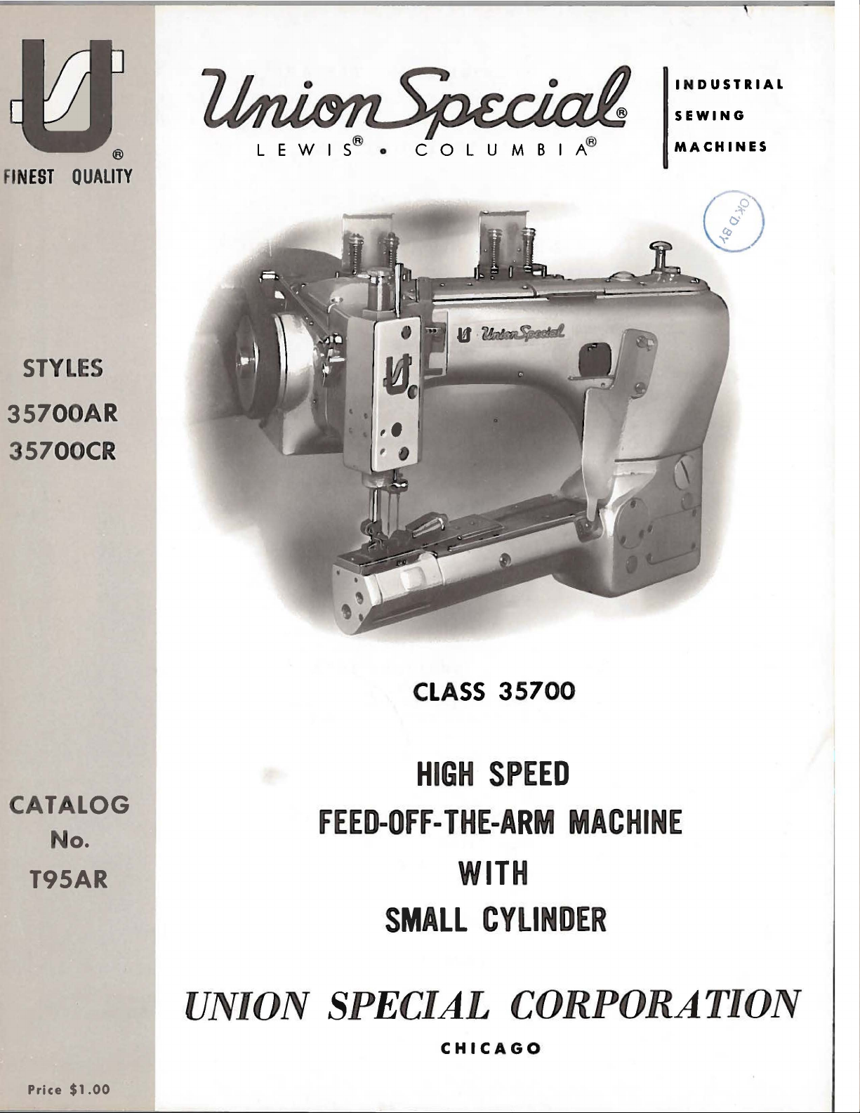
CLASS
HIGH
FEED-OFF-
THE-ARM
SMALL
35700
SPEED
WITH
CYLINDER
UNION SPECIAL
CHICAGO
Price
$1.00
MACHINE
CORPORATION
Page 2
Catalog
No.
T95
AR
(Supplement
ADJUSTING
35700
to
Catalog
INSTRUCTIONS
FOR
LIST
CLASS
AR
AND
OF
Styles
OPERATING
PARTS
35700
35700
No.
CR
95
W)
First
Copyright
Union
Rights
Special
Reserved
UNION SPECIAL
INDUSTRIAL
SEWING
CHICAGO
Edition
1972
by
Corporation
in
All
Countries
CORPORATION
MACHINES
Printed
in
2
U.S.
A.
August,1977
Page 3
IDENTIFICATION
OF
MACHINES
Each
into
the
name
special.
tain
letter
suffixed
which
35700".
junction
Styles
the
page
numbers,
are
illustration.
the
part
herein.
Class
given
of
handwheel
Standard
the
letter
"Z".
to
Styles
differs
This
therewith.
35700
opposite
reference
number
This
It
35700.
from
UNIONSPECIALmachine
plate
"Z".
When
the
Standard
of
machines
from
catalog
AM
description
numbers
Reference
catalog
can
also
Reference
the
operator's
is
counterclockwise.
on
the
machine.
Style
only
the
is a supplement
or
the
listed
applies
be
numbers
Example:
minor
Style
similar
style
APPLICATION
Only
those
CM
are
illustration
and
number
only
numbers
in
the
specifically
applied
to
position
number,
illustrated
second
directions,
"Style
changes
number.
and
with
is
identified
have
35700
in
construction
in
to
Catalog
parts
will
should
used
be
of
pieces
merely
column.
to
discretion
while
by a Style
Style
one
Example:
numbers
or
more
AR".
are
made
"Style
are
that
it
contains
OF
CATALOG
No.
on
Styles
and
listed
found a listing
required.
indicate
never
such
the
Standard
seated
be
to
as
used
some
right,
at
number
are
classified
letters
Special
in a standard
95 W
the
the
Style
35700
grouped
no
and
35700
at
the
of
the
Numbers
position
in
ordering
Styles
Special
left,
machine.
letters.
back
which
as
suffixed,
numbers
ARZ".
under a class
should
AR
parts,
of
Styles
front,
but
machine, a "Z"
Example:
be
and
CR,
of
this
with
in
the
of
that
parts.
machines
of
back,
Operating
is
stamped
standard
never
contain
number
"Class
used
in
but
not
catalog.
their
first
column
part
Always
as
machines
etc.,
direction
and
con-
the
is
con-
on
On
part
in
the
use
listed
in
are
Feed-Off-The-Arm
in
Front,
Periphery
Single
and
Filter
35700
shorts,
Table
401-LSc-2.
35700
Each
type
details.
of
the
eye.
which
Selection
used.
stitch
Light
of
Cylinder
Disc
AR
CR
number
blade,
Collectively,
is
Thread
formation.
Take-up
Type
Machine
pajamas
mounted.
Same
UNION
The
size
measured
given
denotes
on
of
should
High
Weight
Oil
Maximum
as
SPECIAL
number,
the
the
at
for
Return
is
equipped
and
Standard
35700
the
type
label
proper
pass
Presser
the
in
STYLES
Speed,
Bar
Needle
Looper
for
AR,
stamped
thousandths
freely
Bar 6 3/8
Threads,
Pump,
with
similar
gauge
recommended
except
needle
kind
number
of
of
all
needles
needle
through
OF
Low
Throw
Mechanism,
Visual
tractor
operations
Nos.
prepared
NEEDLES
has
shank,
on
the
of
and
size
MACHINES
Machines,
Inches.
Automatic
Sight
speed
both a type
needle
an
size
packaged
should
the
type
8,
point,
inch,
number
be
needle
Oil
foot
on
10,
6000
for
shank,
Two
Adjustable
Space
light
midway
and
determined
in
Enclosed
Action
for
felling
to
12
and
R.
P.M.
Pedestal
number
length,
denotes
represent
sold
eye
in
Needles,
Looper
Front
and
medium
groove,
between
of
Type
Supply
sport
16.
Seam
Installation.
and a size
the
the
by
Union
by
order
Left
Needle
Avoid
Needles 8 Inches,
Oiling
Gauges.
shirts,
weight
Specification
number.
finish
largest
the
shank
complete
Special.
the
size
to
produce a good
Motion,
System
blouses,
material.
The
and
other
diameter
and
symbol
of
thread
the
3
Page 4
For
these
is
machines.
backed
quarters
best
results,
They
by a reputation
of a century.
use
are
for
NEEDLES
only
genuine
packaged
producing
(Continued)
UNION
under
highest
our
SPECIAL
brand
quality
name,
needles
needles
~
for
in
the
more
operation
®
,
which
than
three-
of
Standard
has a round
eye,
spotted,
090/036,
To
sample
on
label. A complete
Prices
ments
unless
The
must
bolt
viscosity
Oil
100/040,
have
needle,
are
are
forwarded
otherwise
oil
be
filled
is
filled
THREADING
"D".
the
of
main
the
One
is
frame
gauges.
recommended
shank,
round
chromiumplated
110/044,
needle
or
orders
the
type
order
strictly
net
f.
directed.
has
been
before
of
90
at
drained
beginning
to
125
the
caps
DIAGRAM".
located
under
at
the
the
needle
point,
would
cash
o.
b.
A
seconds
The
front
foot
for
extra
and
is
125/049.
promptly
and
size
read:
and
shipping
charge
OILING
from
to
operate.
at
"A"
and
oil
level
of
the
lifter
Styles
short,
available
and
number
''1
000
TERMS
are
subject
point.
is
made
AND
the
100°
THREADING
machine
Fahrenheit.
"B"
is
cylinder
lever.
35700
AR
double
in
sizes
accurately
should
be
Needles,
to
change
Parcel
to
cover
before
Use a straight
as
illustrated
checked
Maintain
and
at
the
oil
and
CR
is
Type
groove,
struck
070/027, 075/029,
filled,
forwarded.
Type
Post
the
shipping
the
other
level
an
empty
Use
108 GHS,
without
notice.
shipments
postage
and
and
mineral
in
Fig. 1 "OILING
two
sight
is
on
oil
gauges
the
between
108 GHS.
groove,
080/032,
package,
description
Size
090 I 03 6".
All
are
insured
insurance.
the
reservoir
with a Say-
"C"
right
the
side
red
It
ball
a
ship-
AND
and
of
lines
The
machine
action
and
when
of
the
back
beginning
necessary
To
do
holes
screws.
and
If
inoperative.
Oil
maybe
is
located
below
the
Keep
ion
discs
A
convenient
ers
are
at
of
position,
position.
oil
top
covers.
to
prime
this,
operate
oil
in
the
handw
the
threads
"M"
and
the
left
leaving
is
can
to
operate
remove
machine
does
drained
bottom
heel.
"N".
means
end
equipped
be
observed
When
the
pump.
the
not
bubble
from
of
in
the
Avoid
for
of
their
them
easily
with a continuous
through
starting
a
machine
two
until
when
the
the
cylinder
slots
crossing
threading
travel,
a
that
plug
screws
bubbling
machine
machine
"K"
in
the
press
new
threads
accessible.
the
lucite
machine
has
"G".
can
at
two
and
the
the
tension
loopers
After
4
running
been
be
is
places,
other
as
have
the
knob
rotary
windows
after
idle
Apply
oil
observed
running,
"H"
at
the
posts
much
as
been
"P"
threading,
driven
"E"
filling
for
some
from
at
the
the
circulating
and
back
"L"
and
possible.
provided.
and
loopers
push
and
"F"
the
reservoirs
time,
an
oil
windows.
"J".
One
of
the
between
When
loopers
oil
can
main
will
pump.
in
the
it
to
Replace
pump
plug
the
the
back
back
The
front
may
these
screw
frame
tens-
loop-
into
or
be
is
out
Page 5
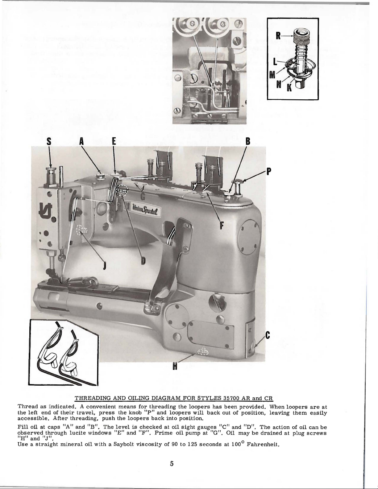
THREADING
Thread
the
accessible.
Fill
observed
"H"
Use a straight mineral
as indicated. A convenient
left
end
of
the
ir
travel,
"A"
and "B". T
gh
lucite windows
oil
and
at
throu
"J".
After thr
caps
eadin
oil
g,
AND
OILING
push
he
means
the
the
level
"E"
knob
loopers
and
press
with a Saybolt
for
"P"
is
checked
"F".
viscosity
DIAGRAM
threading
and
loopers
back into
at
oil sig
Prime
of
90
FOR
the
loopers has
position
ht gauges
oil
pump
to
125 s e
STYLES
will
back
.
at
conds
35700
out
"C"
"G".
5
been
and
Oil
at
100°
AR
provided.
of
position,
"D".
may
and
CR
When
leaving
The
be
drained
Fahrenheit
action
at
.
loopers
them easily
of
oil
can
plug
screws
are
at
be
Page 6

SYNCHRONIZING
NEEDLE
AND
LOOPER
MOTIONS
Needle
before
leaving
become
or
looper
be
required
of
an
adjustable
crankshaft
To
needles,
Rotate
the
just
Fig.
needle
steel
inches
screw
looper
cal
the
needle
begins
2)
from
rod
long)
(A).
holder
position
Continue
extreme
handwheel
bar
until
plate.
gauge
flush
(E).
until
At
(C)
against
Rotate
the
upstroke
edge
ance
of
the
between
and
looper
the
necessary
drive
to
facilitate
to
the
synchronize
presser
handw
bar
is
its
upward
and
remove
the
(B)
(5/32
into
It
may
so
when
to
turn
left,
replace
in
operating
rod
(B)
this
No.
point,
21225 H around
the
handwheel
gauge
of
contacts
the
needle
throat
gauge
mechanisms
factory,
to
disassemble
mechanisms,
proper
split
main
coupling
shaft,
the
foot,
heel
at
throat
in
the
operating
bottom
travel.
the
looper
looper
or
the
be
that
at
the
holder.
11/64
looper
necessary
the
rod
its
farthest
handwheel
the
direction,
contacts
clamp
underside
in
the
bar
plate.
Maximum
and
are
to
insure
the
main
re-synchronization
sewing
located
which
in
machine,
plate
and
direction
of
its
Loosen
for
Insert
inch
diameter
holder
(B)
and
to
re-position
will
be
travel
until
throat
plate.
raising
the
edge
Union
of
the
the
machine
or
the
Special
the
needle
machine
opposite
casting
rod
allowable
machine
casting
carefully
the
best
shaft
adjustments.
beneath
turn
drives
remove
feed
stroke
screw
the
left
a
straight
by 2 1/2
retighten
in a verti-
to
the
right.
the
rod
Turn
the
needle
of
the
throat
timing
bar
casting
direction
on
contacts
clear-
or
synchronized
possible
or
repla~e
of
needle
This
the
rear
the
looper
the
dog.
until
and
(A,
hand
the
is
at
the
(D)
the
the
rod
and
sewing
components
and
is
accomplished
top
throat
with
precision
conditions.
looper
cover,
connecting
mechanism.
Fig.
plate
is . 005
Should
of
the
motions
by
2
gauges
it
needle
will
means
the
inch.
(A,
Fig.
and
the
before
screw
wrench
of
operating
gauge
throat
is
turned
3)
gauge
the
which
in
to
insure
plate
in
Fig.
in
position.
(C,
rod
(B)
was
the
set
direction,
no
in
both,
reverse
3
Fig.
contacts
barely
screw
more
operating
of
If
the
2)
on
the
tightened,
(C,
Fig.
snug-up
than . 005
operating
are
spot
end
(B)
the
several
of
rotation
chronize
three
with
to
zontal
handwheel
the
needle
edge
of
while
3).
Rotate
the
uppermost
inch
and
reverse
direction
Both
secured
screws
of
thread
main
the
the
the
is
bar
the
throat
holding
exists
directions
and
ends
to
and
the
coupling
through
shaft
thousandths
screws,
in
either
the
needle
horizontal
rod
(B,
left,
clamp
turned
(D)
barely
screw
in
contacts
plate,
the
the
handwheel
horizontal
between
the
rod
of
the
the
crankshaft
set
screws.
the
end
of
allowing
direction
and
clamp
Fig.
tighten
enough
reverse
loosen
coupling
clamp
gauge
of
handwheel.
contacts
adjustable
(A,
Fig.
coupling.
the
coupling
larger
several
the
looper.
screws
2)
at
its
the
to
of
operating
the
machine
the
in
place
SLIGHTLY
screw
and
the
split
and
main
On
the
3)
three
The
than
the
to
properly
(B,
farthest
uppermost
hold
horizontal
with
and
casting
If
the
edge
of
coupling
shaft
main
shaft
screws
holes
are
drilled
diameter
degrees
syn-
Loosen
Fig.
3)
position
hori-
the
coupling
direction
casting
clamp
an
Allen
in
reverse
use a shim
or
rod
handwheel
the
throat
by
in
of
the
and
(E)
and
6
Page 7

SYNCHRONIZING
NEEDLE
AND
LOOPER
MOTIONS
(Continued)
plate
turn
end
has
before
the
of
been
curely,
slippage
3
32
inch
looper
versely,
the
3/32
the
handw
the
heel
coupling
accomplished,
recheck
occurred
Fig.
4
gauge
always
inch
looper
clamp
SLIGHTLY
with
both
while
setting
check
the
gauge.
gauge
the
contacts
Allen
tighten
clearance
tightening
fied.
needle,
the
(A)
tion
used
ment
holder,
the
screw
ion
the
and
looper.
(B,
holder,
tating
movement,
after
setting
the
in
the
operating
wrench
the
three
points
the
with
screws.
Insert a new
Always
first.
center
is
3/32
to
the
of
inch,
left.
advantageously
is
required,
allowing
3/32
to
needle
the
inch
(A,
Fig.
assure
and
descending
This
Fig.
5)
yet
rigid
machine
retighten
setting
of
the
the
looper
machine
direction
in
the
horizontal
a .
SETTING
set
adjust
Set
the
the
needle
when
Looper
in
loosen
movement
dimension
5).
Rotate
that
the
as
close
needle
adjustment
slightly,
enough
through
looper
to
casting,
set
005
of
needles,
the
looper
the
making
looper
so
screw
to
the
while
screw.
clamp
inch
THE
shim
LOOPER
looper
so
(B)
to
looperis
gauge
this
screw
in
either
as
shown
handwheel
point
as
possible
barely
can
be
the
looper
to
retain
its
cycle
(B).
the
back
back
of
adjust
holding
After
screws
gauge
type
(A,
Fig.
that
the
point
at
No.
adjustment.
(A,
in
in
passes
brushes
made
by
can
its
to
obtain
Always
of
the
the
needle
as
before,
the
main
this
adjustment
(B,
Fig.
to
assure
and
size
4)
for
the
distance
of
the
its
farthest
21225-3/32
Fig.
5)
direction
Fig.
4,
operating
to
the
without
the
back
contacting
loosening
be
moved
position
the
check
needle
after
except
shaft
3)
se-
as
speci-
the
left
from
looper
posi-
can
If
adjust-
in
looper
to
obtain
retighten
directrear
of
screw
in
while
ro-
required
the
3/32
and
con-
setting
no
be
of
the
the
If
more
a
void
remove
cover,
front
er
Fig.
joint
slot
of
moving
motion
located
left
avoid
8).
downward
increases
looper
it
the
side,
link
r e v e r s e .
joint
securely.
SETTINGS
Set
the
This
is
the
height
set
teeth
of
screw
extend
the
elongated
purpose.
(G)
flush
After
against
or
is
cylinder
at
loosen
ball
Moving
in
avoid
upwards
Retighten
RE-CHECK
AS
feed
neutral
feed
(D).
The
the
slot
in
less
looper
required,
the
lower
joint
the
the
the
amount
motion,
acts
BEFORE.
bar
eccentric
position
bar,
height
depth
the
feed
the
proper
the
bottom
side
loop-
(A,
ball
lever
the
ball
SETTING
of
if
required.
of
of a tooth
dog
height
of
pin
(C,
eccentricity
The
the
feed
above
for
its
attaching
has
feed
dog
THE
Fig.
feed
dog
the
been
(E)
FEED
5)
with
but
can
bar
(E)
is
throat
screw
obtained,
and
tighten
Fig
DOG
the
slot
be
turned
eccentric
set
correctly
plate,
(F)
position
support
. 5
in a horizontal
to
raise
pin
is
held
when
at
high
point
has
been
the
screw
or
in
position
the
of
travel.
provided
feed
dog
(H) s
position.
lower
tips
of
for
support
ecurely.
the
by
its
The
this
7
Page 8

The
plate.
link
(B),
(A).
Whenever
recheck
feed
dog
Adjustment
rotate
the
rear
should
can
feed
the
needle
SETTING
have
be
made
bar
eccentric
position
guard
equal
by
of
feed
setting.
THE
FEED
clearance
loosening
driving
bar
DOG
at
set
screw
stud
(C)
eccentric
(Continued)
both
ends
(A,
as
required,
driving stud
of
Fig.
its
travel
6)
in
retighten
has
feed
been
in
the
bar
set
throat
driving
screw
changed,
ALIGNING
Align
No.
21227
machine,
Fig.
The
height
the
needle's
points
tighten
even
screw
AND
the
AK-
using
7
of
the
eyes
with
(D).
SETTING
needle
of
the
test
needle
are
the
bar
(A,
gauge
pins
(C)
(D)
permitting
pins
the
the
shoulders
seated
needle
set
tighten
are
set
specified,
Fig.
needle
oblique
correspond
faces
bar
1/64
right
HEIGHT
Fig.
number
No.
699 D.
in
needle
into
needle
bottom
on
the
bar
at
its
screw
If
test
not
available,
of
needles,
7)
slightly,
bar
position
of
the
is
correct
inch
side
below
of
OF
NEEDLE BAR
7)
with
applicable
bar
alignment
the
test
bar
connection
of
its
of
the
test
is
now
proper
(D).
plate
type
loosen
lower
as
required
of
with
rear
when
the
the
needles.
test
plate
to
Loosen
connection
plate.
travel
test
plate
aligned
height.
and
insert
and
the
the
needle
underside
of
and
pins
(B),
test
size
screw
and
until
needles
vertical
guard.
the
screw
(E)
a
top
While
(B)
the
(E)
test
With
at
the
(C)
the
and
Re-
pins
new
as
(D,
turn
the
of
of
the
loopers,
maintaining
Fig.
with
both
6
the
looper
positions,
Set
the
ly
contacts
tion.
have
the
with
the
cylinder
frame.
Moving
moving
It
sb:>uld
its
guarding
points
the
right
When a change
large
just
Loosen
the
it
SETTING
rear
the
of
plug
feed.rocker
downward
needle
needles
be
the
loopers,
side
CHANGING
screw
below
feed
REAR
when
set
vertically
surface
of
the
in
stitch
located
the
rocker
acts
guard
at
in
contact
moving
needles.
STITCH
joining
driving
driving
the
reverse.
NEEDLE
horizontally
its
extreme
as
low
with
to
the
LENGTH
length
in
the
line
link
is
left
of
link
upward
GUARD
so
that
forward
as
possible,
the
needles
right,
required,
forward
cylinder
screw
Retighten
(B,
in
8
it
bare-
posi-
are
remove
side
and
Fig.
the
lever
link
main
yet
until
even
of
8).
screw
slot
lengthens
securely.
Fig.
8
the
stitch,
Page 9

The
tension
sistent
threads
amount
nuts
with
should
(R,
their
be
THREAD
of tension
Fig.
1).
strength
barely
to
inch
presser
is
Facing
the
counterclockwise
lease
on
needle
Set
the
and
avoid
sufficient
The
thread
function
above
foot
necessary,
the
machine,
action,
TENS
and
tension
puckering
to ste
tension
as
the
the
throat
has
loosen
tension
insert
as
ION
AND
looper
on
the
ady
presser
plate
reached
release
screwdriver
to
advance
required.
RELEASE
threads
needle
the
fabric.
them
release
foot
and
its
screw
Retighten
in
passing
is
is
highest
(A,
shaft
or
is
regulated
threads
The
set
correctly
is
raised
entirely
position.
Fig.
into
(C)
9)
from
slot
clockwise
screw
by
four
as
tight
tension
through
on the
the
when
approximately
released
If
in
lifter
the
pulley
in
shaft
to
retard
(A).
knurl
as
is
con
looper
machin
it
begins
1/8
when
the
adjustment
lever
(B).
end
and
rotate
the re-
ed
-
e .
of
Fig.
Set
the
let
(A,
Fig.
the
frame
liminary
between
centerline
Start
eyelet
mately
from
and
sewing
(A)
75
thread
20
to
downstroke
take-up
in
the
needle
the
needle
(C)
needle
bar
needle
thread
Regulate
enough
is
pressure
placed
9
adjustable
10)
in
needle
thread
setting,
centerline
of
mounting
on a piece
up
or
down
to
80
percent
cone
25
percent
of
needle
so
that
lever
at
the
thread
loop,
the
on
on
the
fabric.
frame
the
lower
eyelet
approximately
of
thread
screw
of
as
required
of
on
tl1e
upstroke
of
thread
bar.
it
barely
Set
thread
bottom
take-up
presser
the
if
desired
presser
of
(C)
spring
SETTING
needle
mounting
(B)
and
openings
(See
material
until
the
thread
of
is
drawn
the
needle
contacts
eyelet
its
stroke.
will
produce
to
suit
PRESSER
regulating
foot
thread
as a pre-
23/32
Fig.
and
approxiis
needle
the
(D)
with
sewing
FOOT
to
feed
NEEDLE
AND
eye-
hole
inch
and
10).
adjust
drawn
bar
on
the
thread
thread
the
Raising
more
screw
the
THREAD
FRAME
of
conditions.
PRESSURE
(S,
work
uniformly
EYELET
Fig.
1)
TAKE-UP
Fig.
so
that
10
it
exerts
when a slight
only
tension
9
Page 10

--......Q;,J..-22
~rl~
r~-_
10
16
21
23
Page 11

The
ively
Styles
described
represent
35700
Use
parts
AM
Catalog
in
this
illustrated
the
parts
and
CM
No.
95 W
catalog.
on
pages
that
respectively.
(Styles
10
are
and
used
35700
12,
on
AM
described
Styles
and
35700
CM)
below
AR
for
all
and
and
parts
on
CR,
page
but
not
illustrated
13
not
respect-
used
on
or
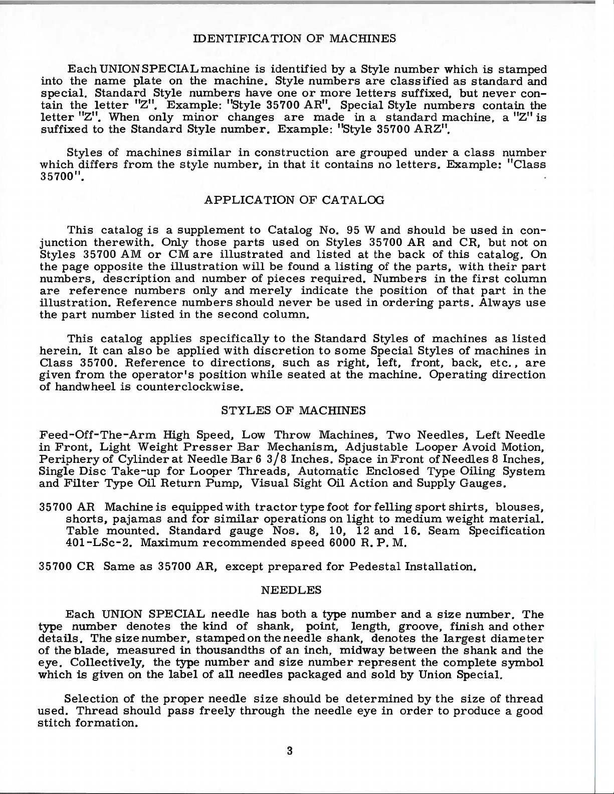
Reference
indented
Ref.
No.
1
2
3
4
5
6
7
8
9
10
11
12
13
14
15
16
17
18
19
20
21
22
23
24
25
26
27
28
29
30
31
32
33
34
35
36
37
38
39
40
41
42
43
numbers
descriptions,
Part
No.
51292
35897
22571 B
35772
35772
22653
35876
36297
35883
35883
35856
36297
36284
36249
22560
36297
36286
36286
22766
22539
35787
36238
36237
22798
36284
35850
35883
22791 E
36256
36283
35883
22585 c
35883
35883
22564
F-8
660-207
CB
s
28
T
E-20
u
E
T
s
AA
G
531
c
A
A
660-202
H
A
s
531
87 A
H
E
F
E
531
D
89
R
B
c
u
N
p
J
that
are
inside a bracket
indicate
Needle
Oil
Oil
Cast-off
Screw
Cast-off
Screw
Washer--------------------------------------------
Oil
Cylinder
Cylinder
Looper
Oil
Screw
Cylinder
Looper
Screw
Oil
Oil
Gasket---------------------------------------------
Cylinder
Screw---------------------------------------------
Plug
Screw
Screw
Cylinder
Cylinder
Bushing,
Screw
Upper
Screw
Looper
Screw
Cylinder
Screw
Cylinder
Cylinder
Cylinder
Screw
Folder
Folder
Screw
they
are
component
Thread
Seal
Ring---------------------------------------
Pump
Plug
Intake
Filter
Seal
Drainage
Housing
Screw-------------------------------------
Plate
--------------------------------------------Plate
---------------------------------------------
Cover------------------------------------Cover
Thread
---------------------------------------------
Cover
Shaft
---------------------------------------------
Ring---------------------------------------
Side
Screw-----------------------------------------
---------------------------------------------
---------------------------------------------
Side
Side
for
--------------------------------------------Lint
--------------------------------------------Shaft
---------------------------------------------
Hinged
Pin
Looper
Hinged
Cover
---------------------------------------------
Gib,
Gib,
---------------------------------------------
Tension
Cover,
Eyelet,
Eyelet,
Filter
Assembly
Shield-----------------------------------
-----------------------------------------
Screen
Gasket
Shield
and
Bushing,
Screw
Cover
Cover--------------------------------Cover
feed
bar
Bushing,
Cover
Thread
Cover
Spring
left
------------------------------------
right-----------------------------------
or
box
on
parts
Description
Spring------------------------
rear-------------------------front--------------------------
-----------------------------
------------------------------
-------------------------------
--------------------------------
Oil
Gauge,
front
---------------------------------
--------------------------------
Gasket--------------------------
eccentric
rear--------------------------
-----------------------------Guide
Spring Support Stud
------------------------------
of a complete
front
front------------------
-------------------------
Wire
the
picture
----------------------
stud------------------
------------------
plates
part
------------
and
or
assembly.
hav
Amt.
Req.
2
1
1
1
1
2
1
3
3
1
1
1
1
1
1
1
1
1
1
1
1
1
4
1
2
3
1
1
1
1
1
1
1
1
1
1
1
1
1
1
1
1
8
e
11
Page 12

~10
4
11
12
"--
23
17
12
Page 13

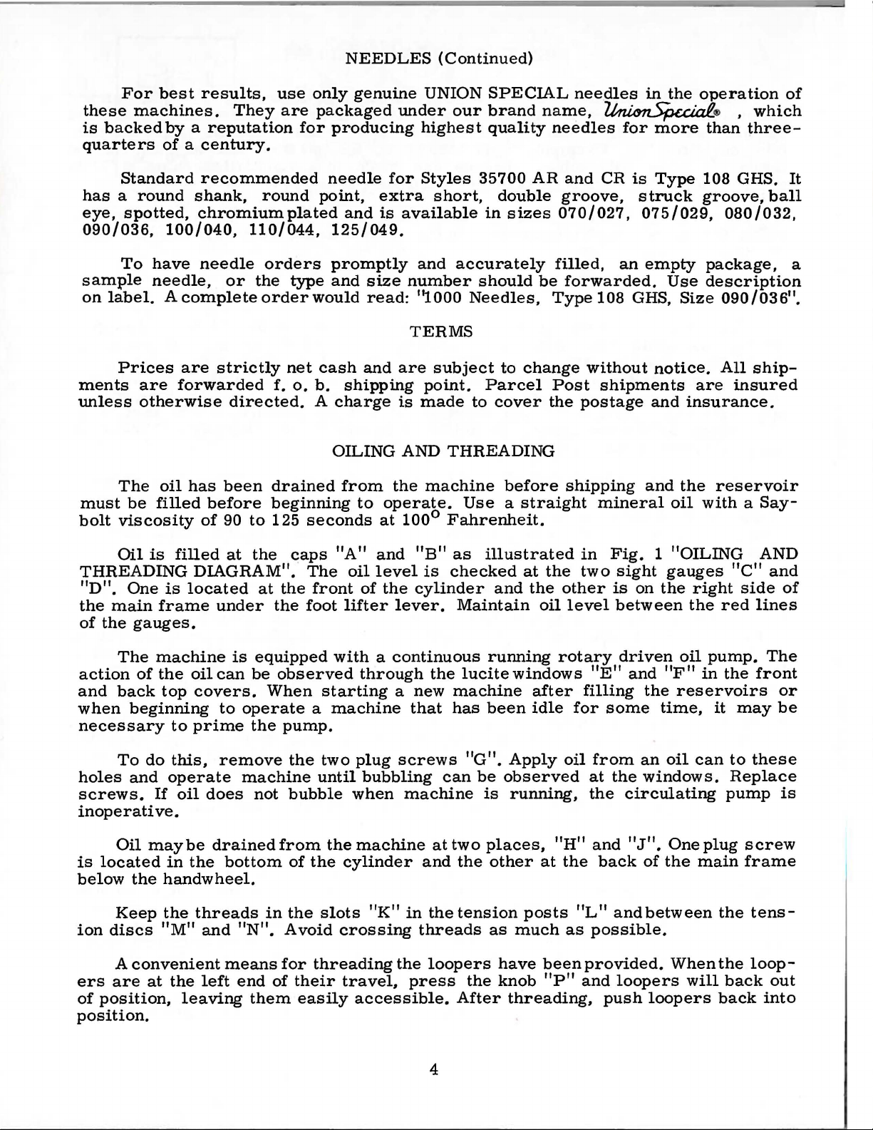
FEED
LIFT,
FEED
DRIVE
AND
LOOPER A
VOID
MECHANISM
Ref.
No. No.
1
2 35834 X
3
4
5
6
7
8
9
10
11
12
13
14
15
16
17 29478
18
19
20
21
22
23
24
25
26
27
28
29
30
31
32
33
34 35766 B
35
36
37 35851 K
38 56341 F
39
40
41
42
43
44
45
46
47
48
49
50 35836 c
51
52
53
54 77
55
56
57
58
59
60
61
62
63
64
65
66
67
Part
22528
33174 B
29478
29103 s
22587 E
PI-18
22894
22894
269
36244
18
36244 A
97
41255 B
22747
29103 G
22587 E
PI-18
88
22764
269
43246
18
35846
22729 c
35846 B
35866
36236 B
660-207
22711
35842 J
36278
29478
35851 M
22560 A
36249 B
22729 D
652 C- 9
36236 A
258
6042 A
36236 H
36236
62238 A
35849 c
36236 A
35736 c
35735 D
35834 AB
22587 H
36234 G
22894
36234 D
35734 B
36234 c
22593
35834 z
35884 K
p
230
660-202
DX
AA
w
A
DW
c
DM
c
Description
Screw,
Feed
Screw
Feed
Ball
Screw-----------------------------------------------------------Feed
Ball
Nut
Bushing,
Oil
Screw-----------------------------------------------------------Feed
Nut,
Stud,
Looper
Screw-----------------------------------------------------------Looper
Feed
Nut
Was
Bushing,
Feed
Link
Feed
Looper
Feed
Feed
Screw-----------------------------------------------------------Feed
Feed
Screw-----------------------------------------------------------Feed
Feed
Feed
Screw
Screw------------------------------------------------------------
Feed
Lower
Oil
for
feed
Bar
Eccentric
-----------------------------------------------------------
Lift
Eccentric
Feed
Lift
Screw---------------------------------------------------Pin------------------------------------------------------
Spot Screw
Set Screw
left
Nut,
Connecting Rod
right
Nut,
Ball
Joint,
Screw----------------------------------------------------
Fork
Drive
Feed
Drive
Screw---------------------------------------------------Pin-----------------------------------------------------Set
Spot
Nut,
left
Connecting Rod
right
Nut,
Ball Joint,
Screw----------------------------------------------------
Stud
Washer----------------------------------------------
-------------------------------------------------------------for
Seal
Ring
Rocker,
for
looper
for
looper
Avoid Link
Screw----------------------------------------------------Ferrule
Connecting Rod------------------------------------------------
Shaft
Screw-------------------------------------------------------Washer
Drive
-------------------------------------------------------------her
---------------------------------------------------------for
Rocker
Pin
---------------------------------------------------------
Rocker
Rocker
Rocker
Rocker------------------------------------------------------
Bar
Drive
Bar--------------------------------------------------------Screw-------------------------------------------------------Feed
Bar
Bar
Eccentric
Bar
Spacer
Bar
Slide Block
------------------------------------------------------------
Dog
Support-------------------------------------------
Lint
Seal
Ring
dog------------------------------------------------
Driving
Assembly--------------------------------------
Eccentric
-----------------------------------------------
------------------------------------------------
thread-----------------------------------------------
-----------------------------------------------
thread----------------------------------------------
complete-------------------------------------------
-------------------------------------------------------Eccentric
Screw-------------------------------------------------
Screw------------------------------------------
thread-----------------------------------------------
thread----------------------------------------------
complete---------------------------------------
feed
-------------------------------------------------Looper
avoid
------------------------------------------------------
Sleeve
------------------------------------------------------
Shaft
feed
Drive
Driving
Shaft-----------------------------------------------
Shaft-------------------------------------------------
Link-----------------------------------------------
Plate------------------------------------------------
Shield
-----------------------------------------------------
Assembly
Eccentric
-----------------------------------------------
drive
Lever
link
shaft
sleeve
Assembly---------------------------------------
-----------------------------------------------
--------------------------------------------------
rocker
Link
Link
Stud
--------------------------------------------------
----------------------------------------------
-------------------------------------------------
Stud------------------------------------
Assembly
Assembly
shaft---------------------------------------
and
assembly---------------------------------
driving
------------------------------------------Screw------------------------------------
------------------
Ball
Joint-------------------------
-----------------------------------Ball
Joint-----------------------
Drive
---------------------------------------
link
Lever
-------------------------------
------------------------
-
------------------------
-- -
-
------
Am
Req.
---
-
---
----1
---4
2
1
1
1
1
---2
2
1
1
1
1
1
1
1
1
1
1
1
1
1
1
1
1
1
1
2
1
1
1
1
1
2
1
1
1
1
t.
1
1
1
1
1
2
1
1
1
1
1
1
1
2
1
1
1
1
2
1
1
1
1
1
1
1
2
1
2
13
Page 14

Union Special
reduce your sewing machine maintenance costs: a record keeping
system to help spot machines requiring
and a parts inventory system to speed routine repairs.
Machine Maintenance Records
Repair-prone machines
up your maintenance
Union Special suggests two variations
record keeping system using cards provided by Union
The first system utilizes a
(Fo
rm
237)
required, the card is
and their cost are entered in the spaces provided and the card is refiled .
is
offering two practical systems to help pinpoint and
abnormally high maintenance,
or
inexperienced competent operators can eat
dollars in short order.
..
for each sewing machine in a plant. When a repair is
pulled
.....
"
........
D4
fl
SYMKIL.fi4Mueflll
Machine Maintenance Record
from
the file and the repair date, parts used,
MACHINE
MAINTaHANCa
.....
~·
I I I I
-
To
help spot these problems,
of
a simple maintenance
lt&CORD
..._.
....
........
•""-.
.,
""'"
.
u•••
Special.
Dot.'h:;PU!Iat
..
-
card
.
and the completion time. This data is then transferred to the permanent
..
Machine Repair Record
Whichever system is used, management now has
to reduce needless maintenance costs.
Repair
Part
While
abnormally high maintenance,
caused by routine repairs.
recommends that manufacturers establish a formal parts inventory
system for each type
Excessive machine downtime and wasted hours
be eliminated with an orderly in-plant inventory
needed parts. There
for
spare parts. Long waits for deliveries are avoided and machine
downtime is kept to a minimum. The cost of a parts inventory is
when the overall savings are considered .
Inventories
record keeping tells management which machines require
MACHINE
RKPAIR
..
kept in the office.
it
does little to help reduce the
To
alleviate this situation, Union Special
of
sewing machine they operate.
is
no longer a need to cannibalize other machines
RECORD
CARD
an
by
mechanics can
of
the most
invaluable tool
downtime
commonly
small
2~1-
fO\tfl\
1
to\llc:"
~e
·
~
~
The second system
on repair costs
Request Card
233). When a machine requires service, the forelady
out
the
top
fills in the time the repair work is started, the parts used and their cost,
Part
Number
35720 AK8
35720 AK10
35720 AK12
35720 AK16
91
35730
73A
35730 AE
73A
35705 AM-8
35705 AM-12
22528
of a ..
AN
is
normally used when more detailed information
is
desired. Two record cards are used: a
..
(Form
234), and a
Repair Request Card
Description
Presser Foot 8 Gauge
Presser Foot 1 0 Gauge
Presser Foot 12 Gauge
Presser Foot 16 Gauge
Clamp Screw For Presser Foot
Spring For Presser Foot
Screw For Attaching Spring
#35730 AN
Spring For Presser Foot
Screw For Attaching Spring
#35730 AE
Feed Dog For 8 Gauge
Feed Dog For
Screw For Feed Dog
10-12-16 Gauge
11
tell
~'c:e
1'\11\Cl
c:otd
-
-
..
Machine Repair Record
..
and gives
-
it
to a mechanic. He
Minimum
Per 5
...
..
·-
..
Repair
..
(Form
or
foreman fills
Quantity
Machines
1
1
1
1
4
2
2
2
2
1
1
1
PARTBU
HD
L-----~--~--~--~------~~
For
free sample copies
inventory lists for a variety
local Union Special Representative
Suggested
Part
Number
35724 AM-8
AM-10
35724
35724 AM-12
35724 AM-16
22524
108 GS
35708
AK
35709 AK
21210 B
22564
22562 A
98
21225-3/32
29484
of
the machine record cards and spare
of
the most popular machines, contact
Minimum
Description
Throat Plate For 8 Gauge
Throat Plate For 1
Throat Plate For 12 Gauge
Throat Plate For 16 Gauge
Throat Plate Screw
Needles (specify size)
Left
Looper
Right Looper
Looper
Collar
Looper Set Screw
Clamp Screw For Looper Holder
Set Screw
Needle
Looper Gauge
Screw Assortment
~
;:
or
write direct
Spare Parts
0 Gauge
~~··==~
to
-
"
";_=_=_=
=
part
Union Special.
List*
Minimum
Per 5
Quantity
Machines
1
1
1
1
6
300
.1
1
4
4
4
4
1
1
your
*The
parts
and
inventory
actual
usage.
of
spare
quantities
The
parts.
nature
listed
An
of
above
efficient
the
sewing
are intended
inventory
can
operation
to
only
assist
will
you
in
be
established
determine
setting
actual
up
the
initial
according
usage.
to
Page 15

Helpful,
cient
types
machine
Sales
Promotion
esting,
obligation
illustrated
authoritative
of
equipment
sewed article
are
the
Department.
bulletins
following:
information
for
is
available
Among
that
on
the
making
from
are available
virtually
Union
the
many
most
effi-
Special's
inter-
without
any
HERE
B
ULLETIN
ARE
HELPFUL
S a
nd CATALOGS
No.
240,
No.
249,
No.
250,
No.
251,
No.
252,
No.
253,
No.
254,
No.
256,
No.
259,
No.
260,
No.
262,
No.
263,
No.
264,
No.
265,
No.
266,
No.
267,
No.
268,
No.
269,
No.
271,
No.
273,
No.
610,
No.
710,
No.
730,
No.
740,
No.
750,
No.
1100,
No.
1105,
"Columbia
ing
Machines"
No.
1500,
"Men's,
"Rainwear"
"Men's
"Service
"Men's
"Overalls, Coveralls, and Dungarees"
"Men's
"Knit
"Men's
"Work
"Cotton,
Bags"
"Men's
"Men's
"Women's
"Women's
"Corsets, Girdles, Brassieres"
"Children's
"Mattresses, Slip Covers,
Upholstery"
"Awnings,
"Curtains & Drapes"
"Kiipp-it"
"MCS
"MCS
Hemmer"
"MCS
"Fusing
"Lewis
stitch,
"Button
"Alteration
Women's,
Dress
Shirts"
Shirts
Shorts and Pajamas"
Knit
Underwear"
Outerwear"
Sports
Gloves"
Burlap,
Clothing"
Women's, Children's
Wear"
Wear
Wear"
Canopies, Tents, Tarps "
ForMation Uni
Automatic
Automatic
Presses"
Blindstitch,
Machines"
Sewers-Ticket
Blindstitch,
Saddle
Department
Children's
and
Pants"
Shirts"
Jute,
And
Dual
Rib-Knit
Footwear"
and
Multiwall
Jackets"
High
Fashion"
Furniture
t"
Underfront
Cuff
Chainstitch,
Tackers"
Stitch,
and
Machines"
Machine"
Lock·
Tie
Paper
Shirt
Clos-
TO
S
HELP
EWING
YO
U
SO
LVE
PROBLEM
S
UNION SPECIAL
fiNEST
QUALITY
CORPORATION
Page 16

.,.o
...
...
'
Q
WORLD'S
,_,lf
FINEST
QUALITY
*
INDUSTRIAL
SEWING
MACHINES
UNION
facilities throughout the
aid
you
SPECIAL
maintains sales
and
world. These offices
in
the selection of the right sewing
equipment for your particular operation. Union
and
Special representatives
tory trained
promptly
tion, there
and
and
is
a Union Special Representative
serve you. Check with
ATLANTA,
BOSTON, MASS.
CHICAGO,
DALLAS,
LOS ANGELES, CAL.
NEW
PHILADELPHIA,
TEXAS
YORK,
GA.
ILL.
N.
Y.
PA.
are
efficiently. Whatever your loca-
service men
able
to serve your needs
him
today.
MONTREAL, CANADA
TORONTO, CANADA
BRUSSELS, BELGIUM
LEICESTER,
LONDON,
PARIS, FRANCE
STUnGART,
service
will
are
fac-
to
ENGLAND
ENGLAND
GERMANY
Representative•
Industrial
UNION SPECIAL
400
N.
FRANKLIN
and
cities
dlstrfbuton
throughout
ST.,
Jn
all
Important
the
world.
CORPORATION
CHICAGO,
ILL.
60610
 Loading...