

Page 1
Industrial
Sewing
Machines
Styles
UNION
List
3S700 3S800
Catalog
SPECIAL
of
in
No.
MACHINE
CHICAGO
Parts
Classes
6SL
COMPANY
Page 2

Page 3
The
parts
only.
UNION
BRANCHES
Boston,
Haverhill,
New
York,
Utica.
N,
Johnson
BiifTalo.
Newark.
F^altimorc,
Greensboro. N C
Union
Special
Union
Si>ecial
Union
Siiecial
Union
Special
Union
Special
Union
Special
Compagnie
Cotnpagnic
Mass.
Mass.
N.
Y.
City.
N.
Y.
SERVICE
N.
J.
Md.
des
des
listed
in
SPECLA.L
Main
AND
Y.
N.
Y
Machine
Machine
Machine
Machine
Machine
Machine
Machines
Machines
CATALOG
LIST
OF
STYLES
IN
35700
this
eatalo<i
MACHINE
Office
and
Factory:
CHICAGO,
SERVICE
Troy.
N.
Y.
Pliiladelpliia.
Pottsville.
Ueading.
Cincinnati.
Clevcl.nnci.
REPRESENTATIVES.
Detroit.
Knoxville,
Atl.mta.
Milwaukee,
BRANCHES—FOREIGN
Cori>oration
Company
Company
Corporation
Corporation
Corporation
Union
Union
Pa.
Pa.
Ohio
Oliio
Mich.
Tcnn.
Ga.
Wis,
of
America.
of
Canada.
of
Canada.
of
America.
of
America.
of
America.
Special
de
Special
de
No.
65
PARTS
CLASSES
and
35800
arc
furnisliecl
400
North
ILLINOIS
STATIONS.
Fa.
UNITED
Ltd.
Ltd.
France.
France.
L
at
list
COMPANY
Franklin
Street
UNITED
Miniicapoiis.
St.
Louis,
Kansas
Los
Angeles,
San
Francisco,
STATES
Fort
Worth,
New
Orleans.
Seattle,
Belgium,
Canada,
Canada,
Denmark.
England.
England.
France,
France.
prices
STATES
Minn.
Mo.
City.
Mo.
Cal.
Tex.
La.
Wash.
Brussels
Toronto
Montreal
Copenhagen
Leicester
London
Paris
Lyons
Cal.
for
repairs
UNION
Berlin
Chemnitz
Argentine
Austria
Australia
Brazil
Chile
China
Cuba
Denmark
Prinlfd
BRANCHES
Buenos
Vienna
Melbourne
Sydney
Rio
de
Janeiro
Santos
Sao
Paulo
Santiago
Valparaiso
Hong
Kong
Shanghai
Tientsin
Havana
Santiago
Aarhus
in
U.
SPECIAL
General
Foreign
Republic
Aires
S.
A.
MASCHINENFABRIK,
Office
aitd
Factory:
AND
SERVICE
Koln
Ehingcn
Distributors
Finland
Tammerfors
Hawaiian
Honolulu
India
Bombay
Calcutta
Ireland
Belfast
Italy
Milan
Japan
Osaka
Tokyo
Mauritius
Port
Mexico
Mexico
Netherlands
.Amsterdam
New
Zealand
Auckland
Christchurch
Wellington
Copyright,
and
Islands
Louis
STUTTGART,
STATIONS,
Service
City
1930,
by
Erfurt
Frankfurt
Stations
Norway
Philippine
Peru
Portugal
Scotland
South
Spain
Sweden
Switzerland
Uruguay
Union
Special
G.
GERMANY
GERMANY
am
are
Found
Oslo
Islands
Manila
Lima
Oporto
Glasgow
Dundee
Africa
Johannesburg
Durban
Capetown
Port
Elizabeth
Barcelona
Boras
Stockholm
Zurich
Montevideo
Machine
m.
Main
in:
Co.,
b.
H.
Chicago,
111.
Page 4
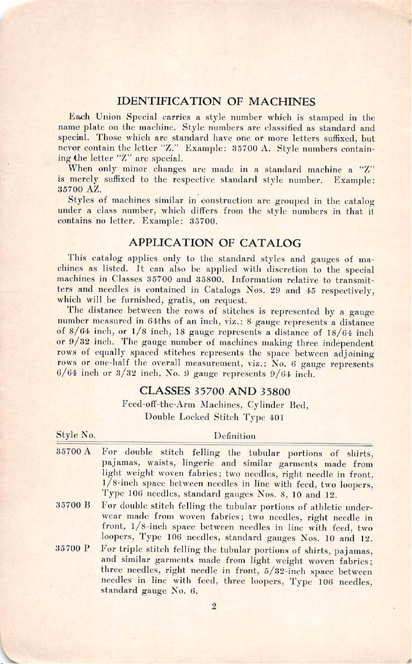
IDENTinCATION
Each
Union
name
plate
on
the
special.
never
ing
is
35700
under a class
contains
Those
contain
the
Icttei*
When
only
merely
Styles
suffixed
AZ.
of
no
the
"Z"
minor
machines
number,
letter.
Special
which
carries a style
machine.
are
letter
"Z."
are
special.
changes
to
the
similar
which
Example:
OF
number
Style
numbers
standard
respective
have
Example:
arc
.'15700
made
standard
in
construction
differs
35700.
from
MACHINES
wliieh
is
are
classified
one
or
more
letters
A.
Style
in a standard
stvie
number.
are
grouped
the
style
numbers
stamped
as
numbers
machine a "Z"
in
standard
suffixed,
contain
Example:
in
the
catalog
in
that
the
and
but
i(
This
catalog
chines
machines
ters
wliich
number
of
or
rows
rows
6/61
Style
85700 A I'or
as
and
will
TJie
distance
measured
8/61
inch,
9/82
inch.
of
equally
or
one-half
inch
No.
listed.
in
Classes
needles
be
furnished,
or
Tlie
or
3/32
Feed-off-the-Arm
double
pajamas,
light
weight
1/8-inch
Type
35700 B For
double
wear
front,
loojjcrs.
For
35700
P
triple
and
similar
three
needles
standard
APPLICATION
applies
between
l/s
spaced
only
It
can
also
35700
and
is
contained
gratis,
the
in filths
gauge
of
inch,
18
number
stitches
the
overall
inch.
No. 9 gauge
CLASSES
Double
Locked
stitch
waists,
lingerie
woven
space
between
106
needles,
stitch
felling
made
from
woven
l/8-incli
Type
space
lOfi
stitch
felling
garments
needles,
in
line
gauffe
right
with
No.
OF
CATALOG
to
the
standard
be
applied
35800.
in
Catalogs
on
rows
of
an
inch,
gauge
of
represents
measurement,
with
Information
Nos.
request.
stitches
viz.: 8 gauge
represents a distance
machines
the
viz.:
represents
35700
felling
fabrics:
standard
needles,
needle
feed,
6.
AND
^Machines,
Stit<'h
Definition
needles
the
fabrics;
between
Cylinder
Tyj)e
the
tubular
and
similar
two
needles,
in
gauges
tubular
two
needles
standard
the
tubular
made
from
light
in
front,
three
loopers,
line
portions
styles
and
gauges
discretion
29
is
represented
making
space
to
the
relative
and
to
15
respectively,
by a gauge
represents a distance
of
18/61
three
independent
between
No. 6 gauge
9/fil
inch.
35800
Bed,
101
portions
garments
right
with
Nos.
8,
10
portions
needles,
in
line
gauges
of
weight
5/32-inch
Type
made
needle
feed,
two
and
12.
of
athletic
right
with
Nos.
10
shirts,
woven
space
106
of
ma
special
transmit
inch
adjoining
represents
of
shirts,
from
in
front.
loopers,
under
needle
feed,
and
in
two
12.
pajamas,
fabrics;
between
needles,
Page 5
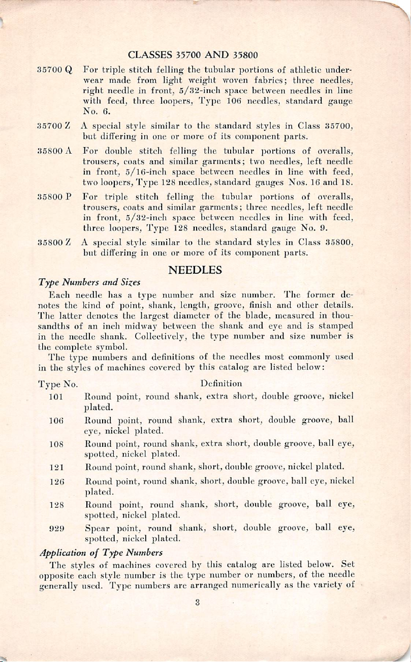
35700
Q
For
wear
right
with
No.
35700Z
35800 A For
35800 P For
35800 Z A
Type
Kach
notes
The
sandtlis
in
the
The
in
Type
101
106
108
121
126
128
929
Application
The
opposite
generally
A
but
trousers,
in
two
trousers,
in
three
but
Numbers
needle
the
kind
latter
denotes
of
the
needle
complete
type
the
styles
No.
Round
plated.
Round
eye,
Round
spotted,
Round
Round
plated.
Round
spotted,
Spear
spotted,
styles
each
used.
special
front,
front,
special
an
symbol.
numbers
of
of
CLASSES
triple
stitch
made
from
needle
in
feed,
three
6.
style
differing
double
loopers.
triple
loopers.
differing
and
has a type
of
inch
shank.
macliincs
nickel
in
stitch
coats
5/l()-ineh
Type
stitch
coats
and
5/32-inch
Type
style
in
Sizes
point,
shank,
the
largest
midway
Collectively,
and
point,
round
point,
round
plated.
point,
round
nickel
point,
round
point,
round
point,
nickel
point,
Type
of
machines
style
Type
round
nickel
Numbers
number
numbers
35700
AND
felling
front,
similar
one
and
similar
one
definitions
covered
the
light
weight
5/32-inch
loopers,
similar
128
felling
similar
NEEDLES
number
between
Type
to
the
or
more
felling
space
between
needles,
garments;
space
between
128
needles,
to
the
or
more
and
length,
diameter
the
of
by
this
tubular
of
the
garments;
the
of
the
Definition
shank,
shank,
plated.
shank,
shank,
round
plated.
extra
shank,
extra
short,
short,
shank,
shank,
plated.
covered
is
by
the
type
are
arranged
this
35800
portions
woven
standard
its
standard
tubular
standard
its
size
groove,
of
shank
type
the
catalog
fabrics;
sjjace
between
100
needles,
styles
component
tubular
two
needles
gauges
three
needles
standard
component
number.
finish
the
blade,
and
number
needles
are
short,
extra
short,
short,
double
double
groove,
double
short,
short,
double
double
catalog
number
or
numerically
of
athletic
three
needles
standard
in
Class
parts.
portions
needles,
portions
needles,
gauge
styles
eye
and
most
listed
double
double
of
in
line
Nos.
of
in
line
No.
in
Class
parts.
The
former
and
other
measured
and
is
size
commonly
below:
groove,
groove,
groove,
nickel
groove,
ball
groove,
groove,
are
listed
numbers,
as
of
the
under
needles,
in
line
gauge
35700,
overalls,
left
needle
with
feed,
16
and
18.
overalls,
left
needle
with
feed,
9.
35800,
de
details.
in
tlmu-
stamped
number
used
nickel
ball
ball
eye,
jjlated.
eye,
nickel
ball
eye,
ball
eye,
below.
the
Set
needle
variety
is
of
Page 6
the
materials
show a preference.
Ordering
To
have
sample
on
packages.
Type
101
sewed
Machine
Style
35700
35700
35700
35700
35800
35800
orders
needle,
An
Size
or
.040."
promptly
the
intelligible
on
each
No.
A
B
P
Q
A
P
type
NEEDLES
style
of
and
accurately
and
size
numbers
order
machine
Type
Needles
101,
101,
101, 106,
101,
121,
121, 126,
will
read
makes
Nos.
of
Used
106,
108
106,
108
108
106,
108
126,
128,
128,
filled,
the
empty
should
be
as
follows:
it
impractical
929
929
package,
given.
See
"100
marks
Needles
to
a
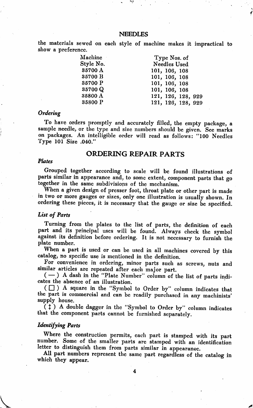
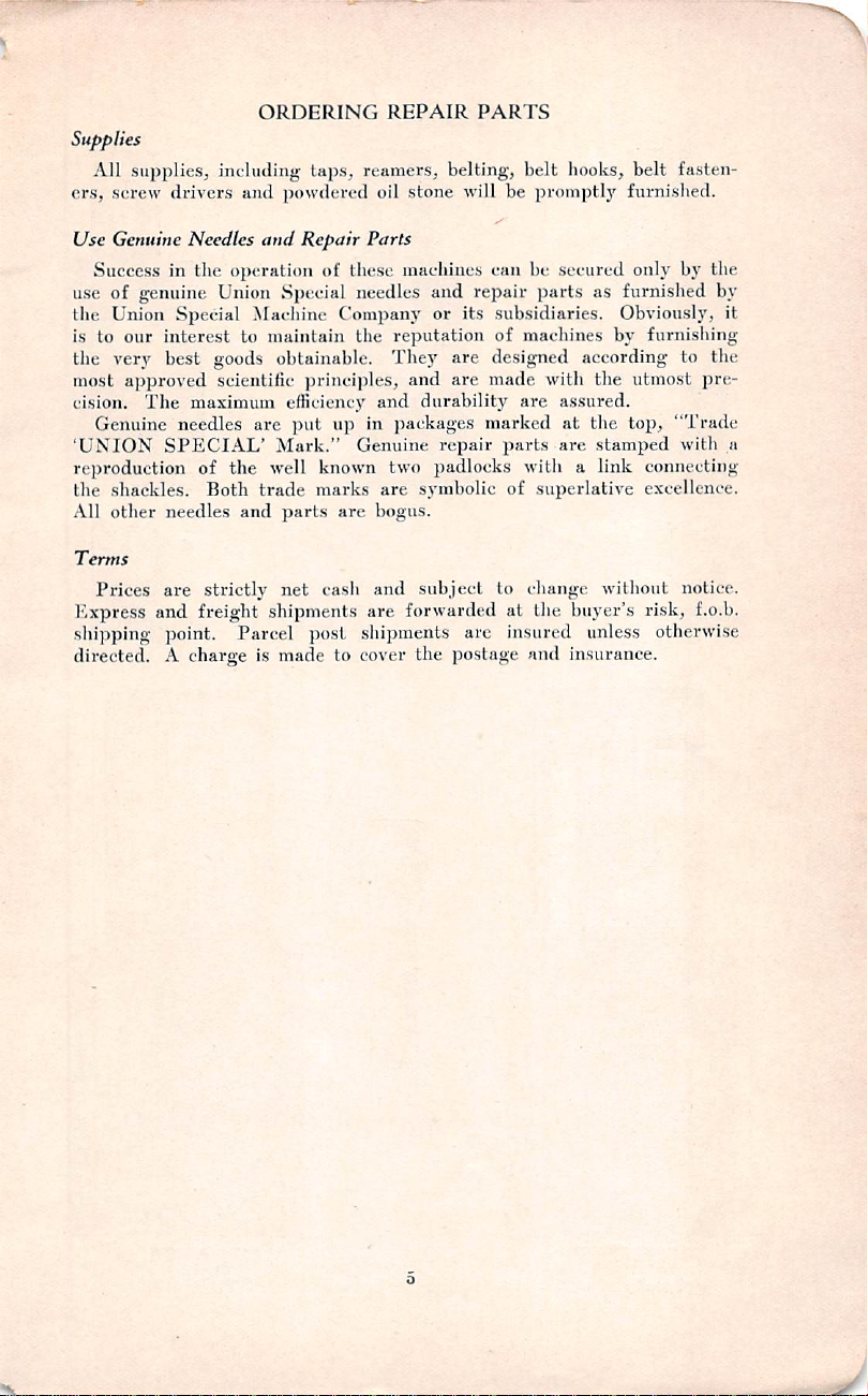
Plates
Grouped
parts
together
together
similar
in
in
appearance
the
same
Wlien a given
in
two
or
more
gauges
ordering
List
part
against
plate
catalog,
similar
( — )
cates
these
pieces,
of
Parts
Turning
When a part
For
from
and
its
principal
its
definition
number.
is
no
specific
convenience
articles
the
are
-A.
dash
absence
( □ ) A square
the
part
is
supply
commercial
house.
( J ) A double
that
the
component
Identifying
Where
number.
letter
All
which
Parts
the
construction
Some
to
distinguish
part
numbers
they
appear.
of
ORDERING
according
subdivisions
design
of
presser
or
sizes,
it
is
the
plates
uses
before
used
or
use
is
mentioned
in
ordering,
repeated
in
the
"Plate
of
an
illustration.
in
the
and
dagger
parts
the
in
cannot
smaller
them
represent
REPAIR
to
scale
and,
to
some
of
the
foot,
only
necessary
to
the
will
ordering.
can
be
after
throat
one
that
list
be
found.
It
used
in
the
minor
parts
each
Number"
"Symbol
can
the
permits,
from
be
readily
"Symbol
be
parts
parts
the
same
to
Order
furnished
each
are
similar
part
PARTS
will
be
found
extent,
component
mechanism.
plate
illustration
the
gauge
of
parts,
the
Always
is
not
necessary
in
all
machines
definition.
such
major
part.
column
of
by"
purchased
to
Order
illustrations
or
other
is
usually
or
size
definition
check
covered
as
screws,
the
list
column
in
any
by"
column
separately.
part
is
stamped
stamped
with
an
in
appearance.
regardless
of
parts
that
part
is
made
shown.
be
specified.
of
each
the
symbol
to
furnish
of
parts
indicates
the
by
this
nuts
and
indi
that
machinists'
indicates
with
its
part
identification
the
catalog
of
go
In
in
Page 7
Supplies
All
supplies,
ers,
screw
Use
Genuine
Success
use
of
genuine
the
Union
is
to
our
the
very
most
approved
cision.
'UNION
rej)roduction
the
All
Terms
The
Genuine
shackles.
other
Prices
Pxpress
shipping
directed. A charge
including-
drivers
in
and
Needles
the
operation
Union
Special
interest
best
needles
SPECIAL'
needles
are
and
point.
to
goods
scientific
maximum
of
the
Both
and
strictly
freight
Parcel
ORDERING
taps,
reamers,
jiowdcred
and
Repair
of
these
Special
Machine
maintain
needles
Company
the
obtainable.
principles,
efficiency
arc
put
up
Mark."
well
trade
parts
net
Genuine
known
marks
are
cash
shipments
post
shipments
is
made
to
cover
REPAIR
belting,
oil
stone
Parts
machines
and
or
reputation
Tliey
are
and
are
and
durability
in
packages
repair
two
padlocks
are
symbolic
bogus.
and
subject
are
forwarded
the
postage
PARTS
belt
hooks,
will
be
promptly
can
be
secured
repair
parts
its
subsidiaries.
of
machines
designed
made
marked
parts
of
to
at
arc
insured
according
with
are
assured.
at
are
with a link
superlative
change
the
buyer's
and
insurance.
belt
furnished.
only
as
furnished
Obviously,
by
furnishing
the
utmost
the
top,
stamped
connecting
excellence.
without
risk,
unless
otherwise
fasten
by
the
by
it
to
the
pre
"Trade
with
a
notice.
f.o.b.
J
Page 8
35705
56
B-2
A-8
fc
lAJklsHsl
Plate
kby/ilslM
1—Full
Specify
Siye
35818
i
Slfc
A
Gauge
n
35724
Specify
Gauge
Specify
A
Gauge
Page 9
llgllj
»l.TMtAM.I
BElflF5frlK
JViiVsfsIk
Specify
Gauge
Specify
Gauge
YFICEPS
TNEMERUSAEM
I;
n
Page 10
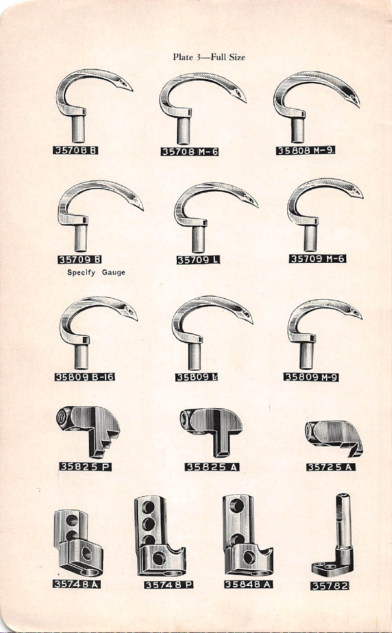
Plate
3—Full
Size
35708
kfcViibWH
Specify
35809
B
Gauge
35708
ECWiEW
M-6
ebeeeeb
35709
KWillKiaBg
M-6
lcM;fcW=l
3572 5 A
r
i
B'
kfcfrAislsl
35848
A
id^
35782
Page 11
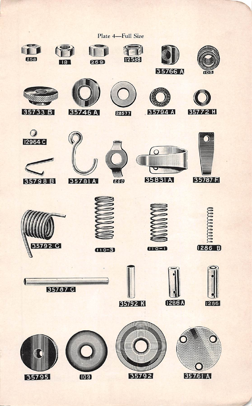
Plate
4—Full
Size
nwjtgm
12964
35798
C
B^H3578I
noi
i
lUlf
icBrei»ii
pTgci
{^M
A
mm
1^0
%J
lsia££K]
m
35831
35772
A^H35787
tma
H
F
35792
C
35787
<ii*n£i
C
i
IWiMsl
«
I
fc
WrlsH
IPItl
E^EK3
Page 12
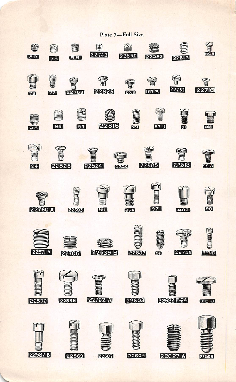
Plate
5—Full
Size
*33
m
isTsi
22760
Qg|
sa
A
ciEm
»fei3
EEI
22525^H22524
22743^B22560
ggi]^
ES
iaa
^
ciaara
cian
^]
f^^VVM
mm
waa»ia
EB
tsUU
S±55
yyxAM
Q)
22513
cosEi
^3
22571
a™
22572
22706
B^»35H
22603
mi
fe
22758
K:fcMaifca
O
22587
B
FCTOTl
22604^H22627
A
hm-tM
Page 13
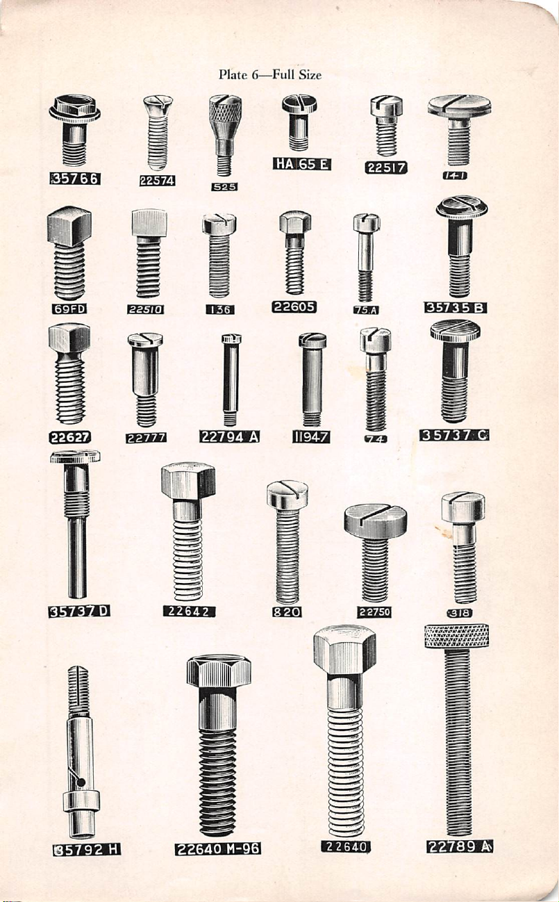
Plate
6—Full
m
Size
225
7
isfeiaij
i$$HrlD
22794
35735
A
KV»*.T.n*4'tfAW4*/»'4
B
&
ehebq
tsWrfr.MSHiia
TO
CT
I
RRWiEM
Page 14
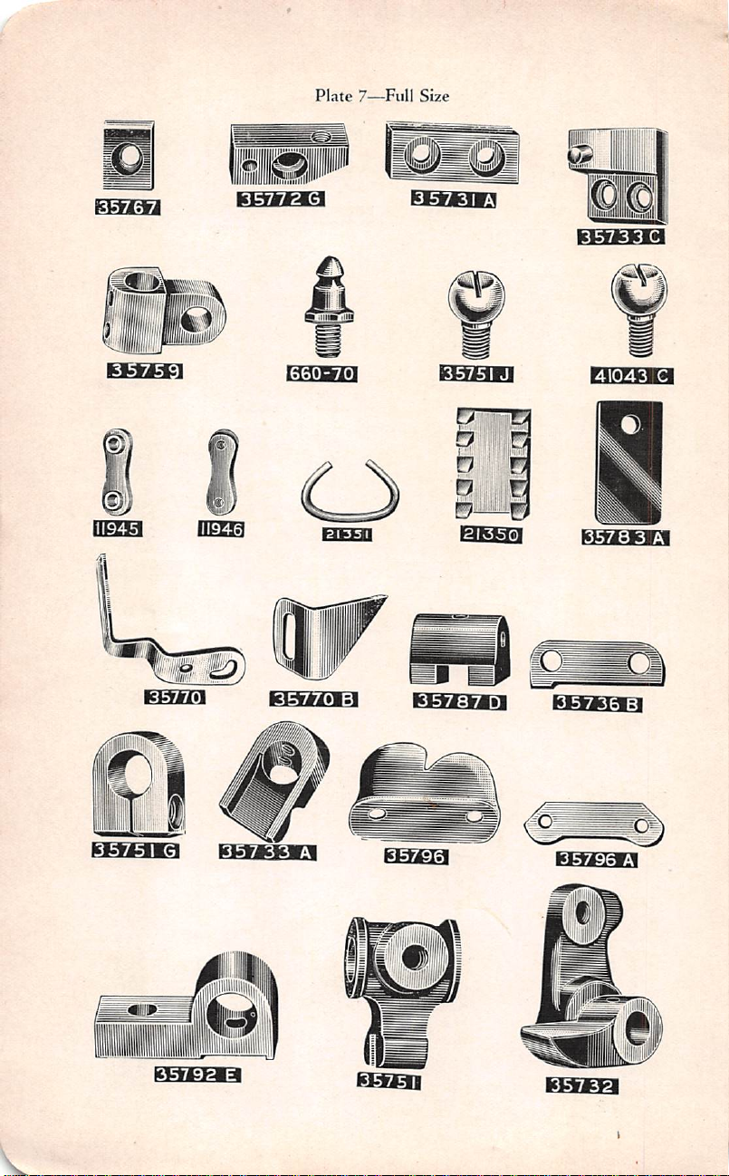
Plate
7—Full
Size
kBBB
EMa
BSiBl
DEES
mm
|cwi»isi
'III
msm
D
U :
f>
E
35733
41043
itgmsgn
C
C
Wi-lEc|
B^BEEa
EBEEa
i
Page 15

iiin
11947
Plate
8—Full
B
Size
BSBH
kLiritHsl
2III3
B
ill
EBBH
EBBB
BHHg
41041
^iligw|^
ro
wanra
2613
A
'i
KTOcIWil
f)
B
35750
A
E^EES
IBEEl
nanut
EE6BEI3
Page 16
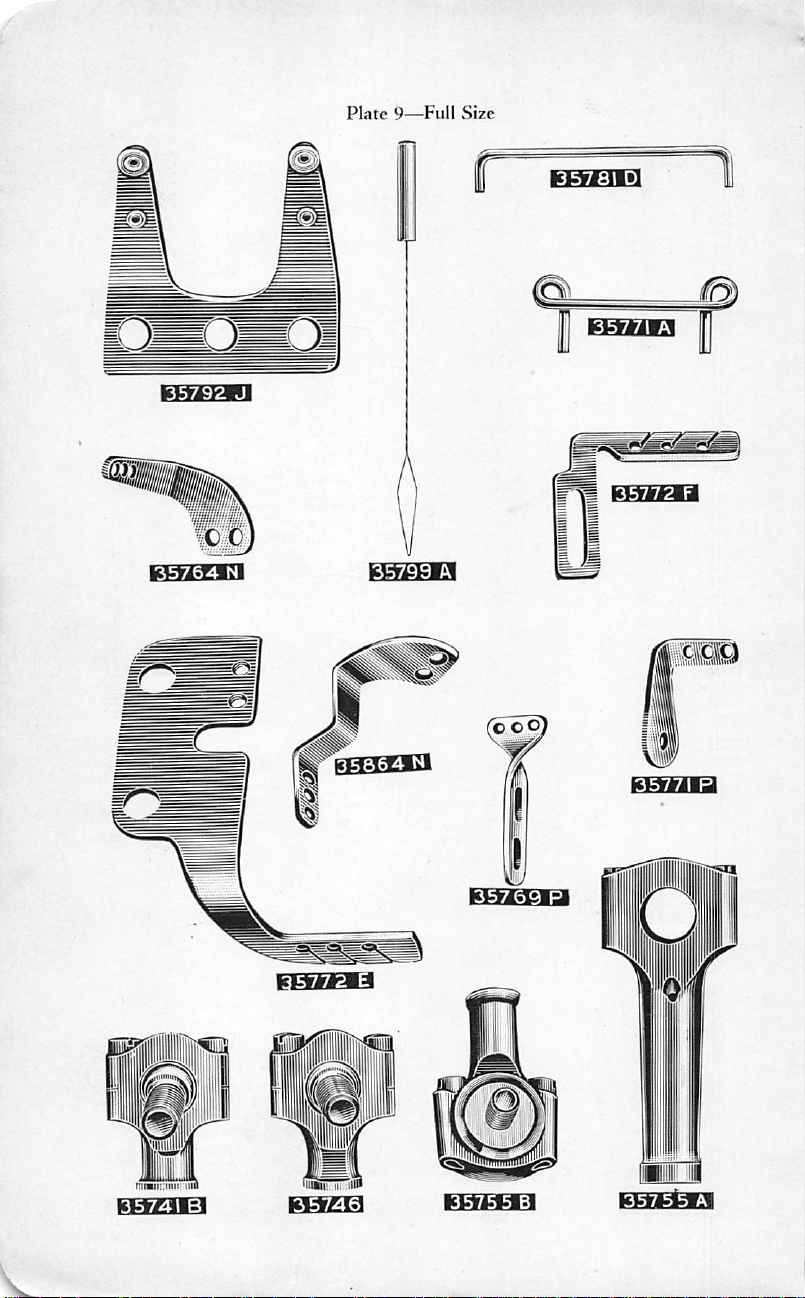
Plate
9—Full
Size
135769
135772
P
F'
Page 17

!B7MB™35713Z^*35773^
specify
and
Capacity
Gauge
klcfViilii
Specify
and
Capacity
Gauge
McgWtlJ
Specify
and
Gauge
Capacity
Specify
and
Capacity
Gauge
Page 18

Plate
E^BH
11—One-Half
Size
EEBIQB
35786
cwra
A
BBaa
/wwww
6oa
35787
B
0
35789 A ^■35787
35789
Page 19

:||8B
Page 20

54
135741A
Q
[/64--I
rG0A73^rG0A-'^M-^57l7p-613
58|7P-9B357^
Page 21

Page 22

caariin
Plate
15—One-Fourth
Size
Uliiinnit
BBE
BSE]
Page 23

bz^eq
Plate
16—One-Eighth
Size
G50AA-28
28561
2168^0
SUBASSEMBLY
28635
2126
5UBAS5EMBLY
22750
4140
BOilliS
N
21680
P
E-78
2
375
R
21680
I
L
i
21375
5
™smsss^55
ASSEMBLY
NO.
28636
N
21375
T
Page 24

1
Plate
17—One-Eighth
21680
L
650
Size
AA-28
mm
ASSEMBLY
28503
NO.
29470
C
Page 25

21680
Plate
18—One-Eightli
0
21680
L
Si/e
2
375
R
ASSEMBLY
ASSEMBLY
NO.
NO.
29470
21375
29470
A
R
B
Page 26
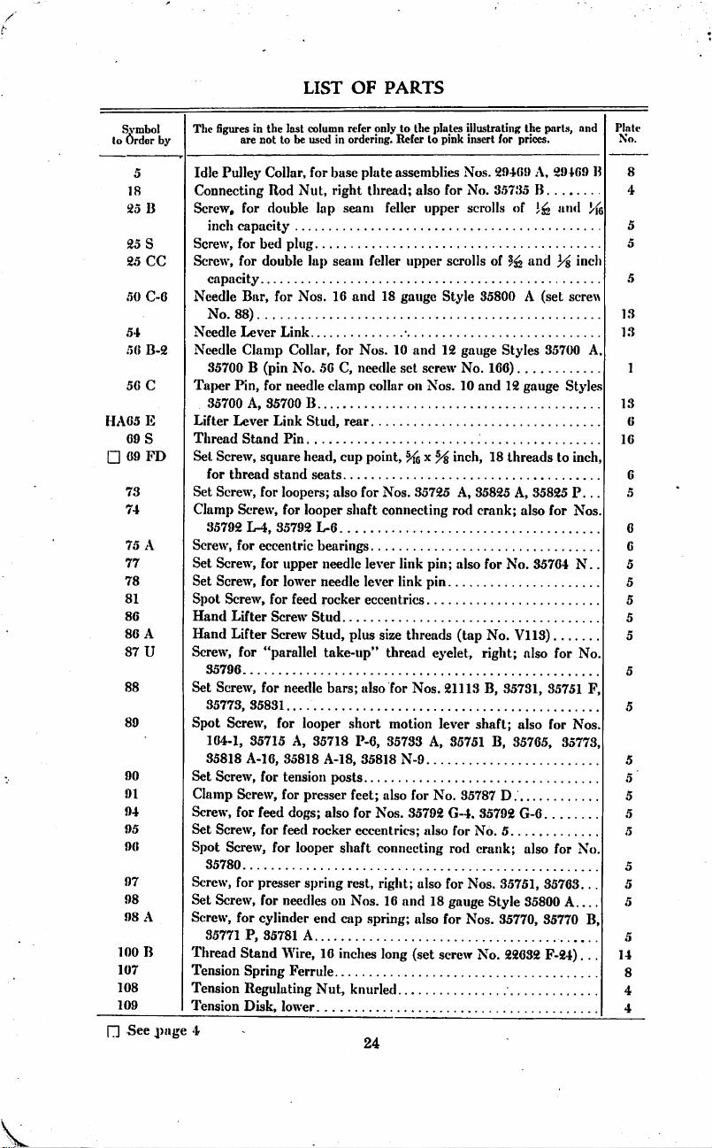
LIST
OF
PARTS
^'mbol
lo
54
HA05
09
□
89
94
95
90
97
98
98
100
107
108
109
□
Order
18
25
B
25
S
25
CC
50
C-6
50
B-2
50
C
E
S
09
FD
73
74
75
A
77
78
81
80
80
A
87
U
88
90
91
A
B
See
by
j)age
The
figures
are
Idle
Pulley
Connecting
Screw,
for
inch
capacity
Screw,
for
Screw,
for
capacity
Needle
Bar,
No.
88)
Needle
Lever
Needle
Clamp
35700 B (pin
Taper
Pin,
35700
Screw,
for
thread
Screw,
35792
Screw,
Screw,
Screw,
Lifter
Lifter
35796
Screw,
35773,
Screw,
A,
Lever
Stand
Screw,
L-4,
for
for
Lifter
Thread
Set
Set
Clamp
Screw,
Set
Set
Spot
Hand
Hand
Screw,
Set
Spot
104-1,
35818
A-10,
Set
Screw,
Clamp
Screw,
Screw,
for
Set
Screw,
Spot
Screw,
35780
Screw,
for
Set
Screw,
Screw,
for
35771
Thread
Tension
Tension
Tension
P,
Stand
Spring
Regulating
Disk,
4
in
the
last
not
to
Collar,
Rod
double
bed
double
for
Link
for
needle
35700
Link
Pin
square
stand
for
loopers;
for
35792
eccentric
for
upper
for
lower
for
Screw
Screw
"parallel
for
needle
35831...
for
35715
35818
for
tension
for
feed
for
feed
for
presser
for
needles
cylinder
35781
Wire,
lower
column
be
used
for
Nut,
plug
lap
Nos.
Collar,
No.
B
Stud,
head,
seats
looper
L-6
feed
Stud
Stud,
looper
A,
35718
presser
dogs;
rocker
looper
spring
end
A
Ferrule
Nut,
refer
in
ordering.
ba.se
right
lap
seam
seam
10
and
for
50
C,
clamp
rear
cup
also
shaft
bearings
needle
needle
rocker
plus
take-up"
bars;
short
P-6,
A-18,
posts
feet;
also
for
eccentrics;
shaft
rest,
on
Nos.
cap
10
inches
knurled
only
Refer
plate
assemblies
thread;
feller
feller
18
Nos.
10
needle
collar
point,
for
Nos.
connecting
lever
lever
eccentrics
size
thread
also
for
motion
35733
35818
also
Nos.
connecting
right;
10
spring;
long
24
to
the
to
also
upper
upper
gauge
and
set
screw
on
Nos.
35725
link
pin;
link
pin
threads
Nos.
A,
N-9
for
35792
also
also
and
also
(set
plates
illustrating
pink
insert
Nos.
for
No.
scrolls
scrolls
Style
12
gauge
No.
10
H
inch,
A,
rod
also
(tap
eyelet,
21113
lever
35751
No.
35787
G-4.
for
No.
rod
for
Nos.
18
gauge
for
Nos.
screw
the
parts,
for
prices.
29409
A,
35735
B
of
of ^ and
35800 A (set
Styles
35700
160)
and
12
gauge
18
threads
35825
A,
35825 P.. .
crank;
also
for
No.
35704 N..
No.
V113)
right;
also
B,
35731,
35751
shaft;
also
B,
35765,
D.
35792
G-6
5
crank;
also
35751,
35763.
Style
35800
35770,
35770
No.
22032
F-24). ..
29409
tind
3^
screw
Styles
to
inch,
for
Nos
for
for
Nos.
35773,
for
A
and
inch
No,
No.
B,
B
J'fe
A,
F,
. .
Plate
No.
13
13
13
10
5
5
5
5
5
5
14
8
4
4
0
0
5
0
6
5
Page 27
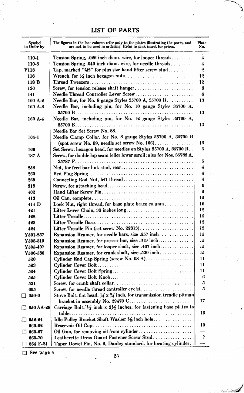
LIST
OF
PARTS
Symbol
to
Order
110-1
110-3
VllS
110
118
136
141
160
160
100
164-1
166
187
258
260
269
318
402
413
414
421
422
423
424
Y501-257
Y503-319
Y505-407
Y506-530
520
523
524
525
531
005
□
050-6
□
6.50AA-28
□
652-24
660-62
□
660-67
660-70
□
664
Q
See
by
B
A-2
A-S
A-4
A
D
F-24
page
The figures
are
Ten.sion
Spring,
Tension
Spring
Tap,
marked
Wrench,
Thread
Tweezers
Screw,
for
Needle
Thread
Needle
Bar,
Needle
Bar,
35700
B
Needle
Bar,
35700
B
Needle
Bar
Needle
Clamp
(spot
screw
Set
Screw,
Screw,
for
35787
P
Nut,
for
Bed
Plug
Connecting
Screw,
for
Hand
Lifter
Oil
Can,
Lock
Nut,
Lifter
Lever
Lifter
Treadle
Lifter
Treadle
Lifter
Treadle
Expansion
Expansion
Expansion
Expansion
Cylinder
Cylinder
Cylinder
Cylinder
Screw,
for
Screw,
for
Stove
Bolt, flat
bracket
Carriage
table
Idle
Pulley
Reservoir
Oil
Gun,
Leatherette
Taper
Dowel
4
in
the
last
not
to
.040
"Q2"
for
inch
tension
Controller
for
inclitding
including
Set
Collar,
No.
hexagon
double
feed
bar
Spring
Rod
attaching
Screw
complete
right
Chain,
Base
Pin
Reamer,
Reamer,
Reamer,
Reamer,
End
Cap
Cover
Cover
Cover
crank
neerlle
in
assembly
Bolt,')^
Bracket
Oil
Cup
for
removing
Dress
Pin,
column
used
.026
inch
inch
for
in
plus
refer
ordering.
diam.
diain.
be
hexagon
release
shaft
I.«ver
No. 8 gauge
pin,
pin,
Screw
No.
for
89,
needle
head,
for
lap
.seam
feller
link
stud,
Nut,
left
thread
head...;
Pin
thread,
for
.38
inches
(set
screw
for
needle
for
presser
for
looper
for
crank
Spring
(.screw
Bolt
Bolt
Spring
Bolt
Knob
shaft,
collar
thread
controller
head, x %
No.
inch
x
Shaft
oil
from
Guard
Fastener
No.
5,
Danley
only
to
the
plates
Refer
to
pink
wire,
for
wire,
for
size
hand
lifter
nuts
hanger
Screw
Styles
35700
for
No.
10
for
No.
12
88.
No. 8 gauge
set
needles
screw
lower
No.
on
Styles
scroll;
Styles
rear
base
plate
brace
long
No.
2281.3)
bars,
size
.257
bar,
size
No.
.319
size
size
98
shaft,
shaft,
eyelet
inch,
for
transmi.ssion
29470
C
inches,
for
Washer % inch
cylinder
Screw
standard,
2.')
illustrating
insert
for
looper
threads
needle
threads
screw
stud
A,
.35700
gauge
Styles
gauge
Styles
.35700
166)
35700
also
for
column
inch
inch
.407
inch
.530
inch
A)
fastening
hole
Stud
for
locating
the
parts,
prices.
B
35700
35700
A,
A,
35700
Nos.
treadle
base
cylinder.
and
35700
B.
.35783
pitman
plates
Plate
No.
4
4
a
12
12
6
(i
13
A,
1.3
1.3
B
1.3
.
A.
4
4
4
C
5
la
16
12
U
12
13
15
15
15
15
11
11
11
6
to
16
10
7
Page 28
LIST
OF
PARTS
^mbol
to
Order
(566-3
666-4
□
667
668-1
668-2
820
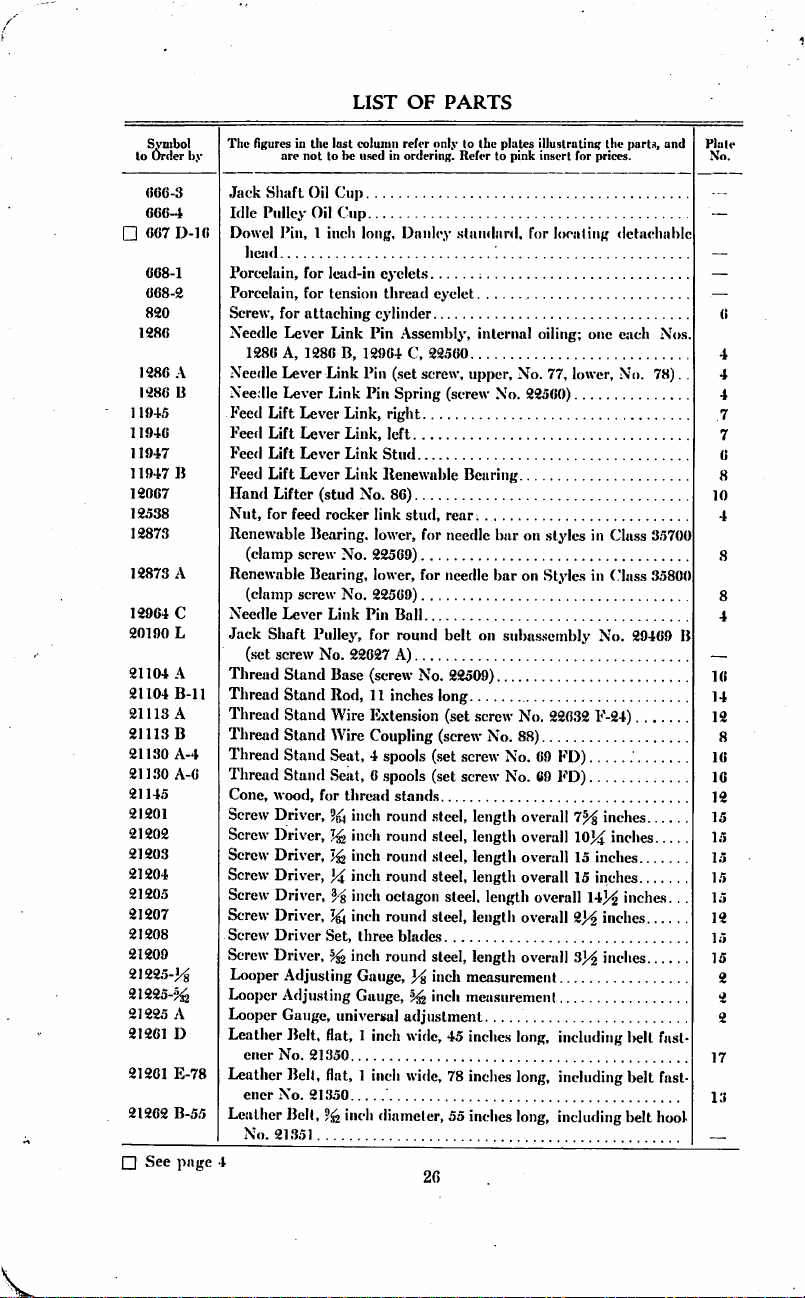
1286
1286
im
11945
11946
11947
11947
12067
12538
12873
12873
12964
20190
21104
21104
21113
21113
21130
21130
21145
2IS01
21202
21203
21204
21205
21207
21208
21209
21225-H
21225-^
21225
21261
21201
21262
□
See
by
D.16
A
B
B
A
C
L
A
B-11
A
B
A-4
A-6
A
D
E-78
B-55
pnge
The figures
are
Jack
Shaft
Idle
Pulley
Dowel
Pin, 1 inch
hejul
Porcelain,
Porcelain,
Screw,
for
Needle
1286
Needle
Needle
Feed
Lift
Feed
Lift
Feed
Lift
Feed
Lift
Hand
Lifter
Nut,
for
Renewable
(clamp
Renewable
(clamp
Needle
Jack
Shaft
(set screw
Thread
Thread
Thread
Thread
Thread
Thread
Cone,
wood,
Screw
Driver,
Screw
Driver,
Screw
Driver,
Screw
Driver,
Screw
Driver, ^ inch
Screw
Driver,
Screw
Driver
Screw
Driver,
Looper
Looper
Looper
Leather
ener
No.
Leather
ener
No.
Leather
No.
21.351
4
in
tlic
last
coluniii
not
to
be
used
Oil
Cup
Oil
Cup
long,
for
lead-in
cyelet.s
for
tension
attaching
Lever
A,
1286
Lever
Lever
Lever
Lever
Lever
Lever
feed
Bearing,
screw
Bearing,
screw
Lever
Pulley,
Stand
Stand
Stand
Stand
Stand
Stand
(stud
No.
for
thread
cylinder
Link
Pin
B,
12964
Link
Pin
Link
Pin
Link,
Link,
Link
Stud
Link
Renewable
No.
rocker
link
lower,
No.
22569)
lower,
No.
22569)
Link
Pin
for
22627
Base
(screw
Rod,
11
Wire
Extension
Wire
Coupling
Seat, 4 spools
Sesit, 6 spools
thread
9^
inch
inch
inch
inch
inch
Set,
three
inch
Adjusting
Adjusting
Gauge,
Gauge,
Gauge,
universal
Belt, flat, 1 inch
21350
Bell, flat, 1 inch
21.350
Belt,
9^
inch
diameter,
refer
only
in
ordering.
Danlcy
eyelet
Assembly,
C,
22560
(set
screw,
Spring
right
left
86)
stud,
for
for
Ball
round
A)
No.
inches
(.set
(set
stands
round
steel,
round
steel,
round
steel,
round
steel,
octagon
round
steel,
blades
round
steel,
inch
inch
adjustment
wide,
wide,
26
lo
the
Refer
to
.staiulard,
internal
upper.
(screw
No.
Bearing
rear.
needle
bar
needle
bar
belt
on
22509)
long
(set
screw
(screw
No.
screw
screw
length
length
length
length
steel,
length
length
length
measurement
measurement
45
inches
78
inches
55
inches
plates
illustrating
pink
insert
for
for
locating
oiling;
one
No.
77,
lower.
22560)
on
styles
in
on
Styles
in
suba.s.sembly
No.
22632
F-24)
88)
No.
69
FD)
No.
69
FD)
overall
7^
overall
10]^
overall
15
inches
overall
15
overall
overall
overall
long,
long,
long,
inches
14)^
2)^
.3)^
including
including
including
the
parts,
prices.
detachable
each
No.
Class
Class
No.
29469
inches
inches
inch&s. . .
inches
inches
belt
belt
belt
and
Nos
78).
35700
35800
B
fast
fast
hool-
.
Page 29

LIST
OF
PARTS
to
□
□
□
□
□
^mbol
Order
21350
21351
21355
21355
21371
21375
21375
21375
21375
21375
21388
21388
21388
21394
21394
21394
21394
21397
21397
21397
21397
21398
21398
21398
21398
21398
21680
21680
21680
21680
21680
21680
21680
22507
22509
22510
22513
by
A
BC
R
S
T
U
V
B
N
G
H
K
A
B
C
D
B
E
F
G
J
L
N
P
Q
R
S
T
The figures
arc
Malleable
Wire
Belt
Chair
Leg
Chair
Leg
Table
Top,
Dress
Guard,
Guard,
for
Guard,
for
Guard,
for
Guard,
for
Wrench,
Wrench,
Double
End
Utility
Grinder,
mended
Emery
Wheel, 5 inches
emery
Emery
Wheel, 5 inches
emery
Utility
Grinder,
mended
Jack
Shaft,
Jack
Shaft
Jack
Shaft
Jack
Shaft
I<lle
Pulley
22627
Idle
Pulley
22509)
Idle
Pulley
Idle
Pulley
Idle
Pulley
Base
Plate
Base
Plate,
Base
Plate
Base
Plate
Base
Plate,
tion.
Base
Plate,
Adapter
Set
Screw,
for
treaclle
Set
Screw,
for
thread
Cap
Screw,
mission
Screw,
for
in
the
last
coluinn
be
used
in
Fastener,
for ^ inch
refer
ordering.
not
to
Iron
Hook,
Belt
Extension, 4 inches
Extension, 6 inches
48
inches
long,
leatherette,
sewing
transmitter
transmitter
jack
shaft
for ^ inch
for
inch
Wrench,
machine
brake
belt
(screw
hexagon
hexagon
for
ffc
including
including 5 inch
speed
3000
R.
P.
diam.
60
diam.
60
including 5 inch
speed
3000
R.
P.
for
subassembly
Hanger
(screw
Pulley,
for flat
Renewable
Shaft,
A)
Shaft
Bracket
Shaft
Brace
for
Brace
Brace
for
for
Plate,
square
pitman
square
stand
square
treadle
thread
Bearing
for
subassembly
for
subassembly
(screw
Hanger
(clamp
Flange
assemblies
Column,
Column,
subassembly
subassembly
for
assembly
head,
cup
connection
head,
cup
rod;
also
head, M x
pitman
controller
only
to
the
Refer
for 1 inch flat
round
belt
long
long
16^
inches
belt
pulley
(screw
No.
No.
22604)
nuts
nuts
and
emery
M
14
inch
)4.
inch
emery
M
No.
29469
No.
22042)
belt
(screw
No.
22605,
screw
Nos.
29470
upper
section
lower
section,
No.
29469
No.
29469
No.
29470 B (screw
point, x ^
point,
for
Nos.
inch,
bracket
rack
guide
plates
illustrating
to
pink
insert
belt
wide.
1^^
fasteners
and
22750)
inch
hexagon
wheel, M inch
face, H inch
face,
y%
inch
wheel,
B
No.
22627
No.
29469 B (set
No.
29469 A (set
washer
No.
22640
A,
29470
(lock
including
A,
open
B
inch,
inch,
21104
A,
20
threads
plate
for
inches
screw
nuts
hole,
hole,
]/%
inch
A)
No.
B
nut
line
No.
20
18
21398
to
the
parts,
prices.
thick.
studs.
face,
recom
grade
grade
face,
recom
screw
screw
652-24)....
M-90)
No.
414
coupling.
shaft
installa
2260.3).
threads
to
threads
to
E
inch,
for
and
.
.
"M'
".M"
No
No
D)
..
.
inch,
inch,
trans
Plate
No.
12
12
Ui
16
16
16
17
12
12
12
16
18
16
7
7
16
18
□
See
page
4
27
Page 30

LIST
OF
PARTS
^mbol
to
Order
22517
22524
22525
225S»
22548
22560
2258!)
22571
22572
22574
22580
22585
22587
22593
22.597
□
22603
□
22004
□22G05
□
22627
r
22627
□
22632
□
22640
□
22640
G
22642
2270!)
22716
22743
22747
22750
22752
22758
22760
22768
22777
2278!)
22792
□
See
liy
B
A
B
A
K-24
A
A
A
pjigc!
The figures
("lamp
35772
Screw,
I
Screw,
'
Ping
Plug
I
Screw,
("lamp
35791
Ping
("lamp
35751
Screw,
Set
Screw,
Screw,
Screw,
(.'lamp
Screw,
Cap
adaplcr
(
ap
shaft
Cap
idle
S«,"l
Screw,
mitter
S«>|
Screw,
.shaft
S<1
Screw,
inch,
Cap
fastening
Clamp
for
Cap
shaft
Ping
Screw,
Set
Screw,
Sr
rew,
.Screw,
Scl
Screw,
Lifter
1
ivot
Screw,
Lifter
Prcsser
(
lamp
4
in
the
arc not
Screw,
E,
35787
for
throat
.010
inch
Screw,
Screw,
for
needle
Screw,
A
Screw,
Screw,
G
for
bed
for
for
needle
for
needle
Screw,
for
machine
Screw,
i)late
Screw,
hexagon
guard
Screw,
hexagon
pulley
square
frame
headle.ss, x ^
jnilley
square
for
tlircii<l
Screw,
hexagon
ma<
Screw,
idle
pulley
Screw,
hexagon
hanger
Screw,
for
for
needle
for
for
"parallel
for
transniilter
for
Lever
Link
.Stud,
for
for
cylinder
Lever
Link
Spring
Screw,
Inst
column
to
lie
used
in
for
looper
E
plates;
plu.s
size
for
eccentric
for
crank
chamber
lever
link
for
needle
for
front
end
for
feed
lift
cover;
ul.so
outer
needles
rear
gniird
lever
jonnecting
for
feed
rocker
pulleys
hexagon
head. x ^
in
assembly
head, ? « x 1
head,
bracket
head, x ^
aligning
.shaft
hea<l.
stand
wire
head, % x
liine
to
base
lic.xagon
.shaft
head, x Ij^
hanger
liea.l, x I
rear
end
of
lever
shaft
hinged
bed
take-up"
belt
middle
nee
Stml.
front
combination
fronl
plate
Bell
Crank
Begulatiiig
hexagon
head,
refer
only
to
the
ordering,
shaft
also
for
thread.s;
bearings
pin
bar
of
cylinder
lever;
for
Nos.
on
holder:
plnles
Refer
in
connecting
Xos.
35767, 35789,
otherwi.se
renewable
also
35721,
Style
35800
also
rod
caps
inch,
No.
29470
iix-h,
16
x
inches,
inth.
18
inch.
18
cup
point,
1%^
inches,
plate
inches,
in<-li,
18
cylinder
end
cfjvcr
cover
jtin
cast-off;
also
guard
lie
on
S(yle
35800
cylitnier
thread
Stud
Thiiiiib.screw
for
looper
holdees
28
itlustrating
pink
insert
rod
crank;
same
bearings:
for
No.s.
35721
P
for
No.
16
threads
B
threads
16
threads
tiireads
x
inch.
16
Ihreads
for
No.
P
eyelet
(lock
nut
the
tor
prices.
also
35789
as
No.
al.s«
35736,
A,
35821.. .
35772
to
inch,
llirettds
to
inch,
to
iin-h.
24
threads
16
threads
to
inch,
35794
and
No.
357.33
parts,
for
A
22524.
for
.35751
G
to
inch,
for
lo
inch,
for
trans
for
threads
to
inch,
to
inch,
for
jack
C
guard.
B).
and
No.s.
No.
A.
.
for!
jack
for
jack
id
for
. .
.
.
Plate
No.
.
:
Page 31

LIST
OF
\
PARTS
Symbol
lo
Order
2«7!)4
A
'£«813
i'iSie
22825
28420
D-8-^
28420
D-fi-Ke
2.8420
1)-I0-J£,;
28420
D-IO-I^I
28420
D-12-^
23420
D-]2->1'6
28420
I'I-H-Im'
23420
F.a-5
28420
F-9-H
23420
P-lO-ife
28421
B.4ti2-?^!
23421
B-5->|
23421
B-8-I^
28421
B-a-1^6
'Die figures
by
Screw,
Set
Set
Screw,
Lap
Lap
Style
Lap
Styio.s
Lap
Lap
35700
Lap
I Style.s
I and
Lap
Lap
Lap
Lap
Lap
Lap
Lap
Lap
in
the
are
not
lo
ftir
"pnraliel
Screw,
for
Screw,
for
for
attacliiiig
Setiin
Feller
capacity,
23421
28423 D and
H-8-J^,
Seam
85700
Seam
for
Feller
Feiler
35700
23422
D-tyi,
Seam
Feiler
Style.s
35700
23422
D-Ke.
Seam
Feller
Styles
35700
Q;
one
and
two
No.
Seam
Feller
35700
35700
Q:
one
two
No.
Seam
Feller
capacity,
gauge
25
capacity,
35800
23423
Style
2.8421
capacity,
23421
187
Style
Style
Style
Style
for
Styles
CC,
23422
Seam
Feller
for
P;
one
E,
and
Seam
Feller
85800 A and
B-S-Js,
Seam
Feller
for
B-4>^-?.t2.
A
Setiiii
Feller
85800 A (screw
Scum
Feller
.85800 A and
Seam
Feller
85700 A (screw
Seam
Feller
35700 A (screw
lust
column
used
refer
in
ordering.
be
iake-iip"
lifter
Ireudle
pin
trnnsinitter
No. 8 gauge
25
A;
one
two
A,
28423
bell
liip
.seam
As.seiiibly,
B,
28422
.Assembly,
each
Nos.
No.
187
Assembly,
35700
B;
I)
and
Assembly,
A.
35700
28423 D and
B;
Assembly,
A,
35700 B and
each
Nos.
23421
187
.A
Assembly,
A,
35700 B and
each
Nos.
23421
187
A
Assembly,
No.
12
gauge
35700
P,
E4^,
No.
two
25
No.
35700
23423 E and
Assembly,
18
gauge
each
Nos.
No.
187
As,senibly,
No. 9 gauge
CC,
28422
As-senibiy,
IG
gauge
25
CC,
Upper
Scroll, % inch capacity,
No.
rpi)er
Scroll, ^ inch
No. 9 gauge
Upper
Scroll,
No.
Vpper
Scroll,
No.
only
(o
llie
plates
Refer
fianye,
retainer
fellers
compensating
Stylo
28428
lie
inch
28421
A
,'32
'"fh
one
eaclt
two
No.
]4i
inch
one
eacli
two
No.
inch
illustrating
to
pink
insert
Tronl
to
throtil
lower
8.5700
D.
and
capacity,
B-B-j-ie,
capacity,
.Nos.
2.8421
187
A
capacily,
Nos.
28421
187
A
capacily,
No. 6 gunge
B-12-h^.
Ifg
inch
capacily,
25
B,
23422
No. G gttiige
B-12-.'
{(,,
25
B,
23422
compensating
Stj-les
Q;
one
two
compensating
Style
35800 A and
23421
A
Is
hidi
Style
V-^,
compensating
Style
28422
25
CC)
lower
35700
.A,
each
No.
187
lower
]L5-?y2.
25
capacity,
35800
28423 F and
lower
85800
F4^.
28428 F ami
capacity,
Style
35800 P (screw
inch
capacity,
25
B)
hie
hicii
capacily,
25
B)...
.
the
parts,
for
price.s.
plate.s
scroll.
A;
one
each
two
No.
187
for
No. 8 gaugt
25
B,
23422
for
No.
10
B-lO-.'^i..
for
No.
10
B-IO-Lj-'b,
for
No.
12
Styles
35700
D-lii.
23423
for
No.
12
Styles
85700
I)-',6.28428L
scroll,
•'32
35700 B and
Nos.
28421
B-l2-?^2.
A
.scroll,
?32
No. 0 gauge
CC,
23422
for
No.
18
P;
one
each
two
No.
187
.scroll,
?y>
one
each
two
for
No.
IG
for
No.
18
No.
25
for
No. 8 gauge
for
No. 8 gauge
and
incl.
No.s.
A..
D4fc.
gunge
25
U,
gauge,
25
B,
gaugcl
P,
D
gauge:
P,
hid.
.No.
t
inch
Style
F4^.
gunge
Nos,
A.
.i
iucli
Nos.
No.
gaugt
gauge
CC)
Plate
j
No.
10
10
10
10
10
in
10
10
10
10
29
Page 32

LIST
OF
PARTS
^mbol
to
Order
23421B-10-1^2
23121B-10-
23421B-12-J^
23421
B-12->fe
23421
B-12-%
23422
23422
D-Pfc
23422
E-^2
23422
F-5^2
23422
23423
D
23423
E
23423
F
28531
28561
28562
28563
28564
28565
28575
28576
88576
A
q28577
28578
28585
28603
[-1^8604
□
See
page
The figures
by
Lap
r.gtp
Lap
Lap
Lap
Lap
Lap
Lap
Lap
Lap
Lap
I..ap
Lap
Belt
Transmission
Transmission
Transmission
Transmission
Transmission
Transmission
Transmission
Transmission
Transmission
Transmission
Transmission
Driving
Transmitter
4
in
the
last
are
not
to
be
Seara
Feller
gauge
Style.s
35700
Seam
Feller
gauge
Style.s
Seam
gauge
35700
Seam
gauge
35700
Seam
gauge
Seam
for
Nos. 8 and
187
A)
Seam
for
Nos.
187
A)
Seam
for
No.
Seam
for
No.
Seam
for
No.
35700
Feller
Styles
P,
35700 Q (screw
Feller
Styles
P,
35700 Q (screw
Feller
Styles
35700
Feller
Feller
10
and
Feller
12
gauge
Feller
16
gauge
Feller
18
gauge
35800 P (screw
Seam
Feller
Styles
in
Class
Seam
Feller
Class
35700
in
(screw
Feller
Class
for
Seam
styles
Retainer,
Treadle
Teadle
Treadle
Treadle
Treadle
Treadle.
Treadle
28636 N (screw
Treadle
29470 C (stove
Trea<lle
Treadle
Treadle
28576
and
28577
Pulley, 9 inch
Lubricant,
coliimn
refer
used
Upper
Upper
Upper
35700
only
in
ordering.
Scroll,
A,
35700 P (.screw
Scroll,
A,
35700 B (.screw
Scroll,
A,
35700 B and
No.
Upper
Scroll,
35700
A,
35700 B and
No.
Upper
Scroll,
A,
35700 B (screw
Compensating
10
gauge
Styles
Compensating
12
gauge
Styles
Compensating
Styles
35700
Compensating
Style
35800 A (screw
Compensating
Style
35800 A and
No.
187
A)
Base,
for
35700
(screw
Base,
for % inch
No.
22825)
Base,
for
5^
35800
(screw
transmitter
Pitman
Pitman
Connection
Pitman
Pitman,
Pitman,
Pitman
No.
22510,
Pitman
bolt
No.
650-6)
Pitman
Base
.Assembly;
diam. flat
No. 3 Arctic
30
to
tlie
Refer
to
inch
inch
inch
25
B)
Vfg
inch
25
B)
inch
Lower
35700
Lower
35700
Lower
A,
35700 B (screw
Lower
Lower
and
No.
22825)
capacity
and
3^
inch
No.
22825)
(screw
No.
Assembly
Cotter
Pin,
upper
section
lower
section
Bracket,
washer
No.
Bracket,
Bracket
one
each
face,
for
cup
plates
illustrating
pink
insert
for
capacity,
No.
25
B)
capacity,
No.
25
B)
capacity,
No. 6 gauge
capacity,
No. 6 gauge
capacity,
No.
25
Scroll,
Scroll,
CC)
inch
A,
35700 B (screw
'"ch
A,
35700 B (screw
Scroll, % inch
No.
Scroll,
5^
inch
No.
187
A)
Scroll, ^ inch
No. 9 gauge
inch
capacity
scrolls
on
capacity
22816)
(set
screw
No.
3^ x ^
inch
for
assembly
28577)
for
a.ssembly
Washer,
3<i
Nos.
28575,
assembly
inch
No.
grease, 5 lb.
the
parts,
prices.
for
No.
for
No.
for
No.
Style.s
for
No.
Styles
for
No.
capacity,
capacity,
capacity,
187
.\).
capacity.
capacity,
Style
scrolls
styles
folders
22507).
22510,
29470
package.
No.
No.
on
on
No.
No.
10
10
12
12
12
in
C
and
.
.
Plate
No.
16
17
16
16
17
4
Page 33
LIST
OF
PARTS
Srabol
to
Order
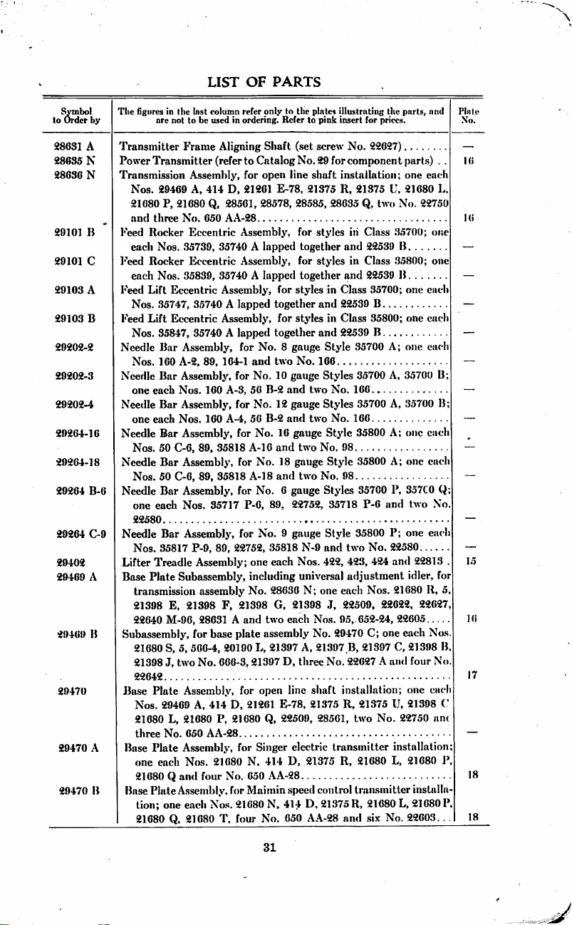
28631
28635
28636
29101
29101
29103
29103
29202-2
29202-3
29202-4
29264-16
29264-18
29264
29264
29402
29469
29469
29470
29470
29470
The figures
by
A
N
N
B
C
A
B
are
Transmitter
PowerTransmitter
Transmission
Nos.
21680
and
three
Feed
Rocker
each
Nos.
Feed
Rocker
each
Nos.
Feed
Lift
Nos.
35747,
Feed
Lift
Nos.
Needle
Nos.
Needle
one
each
Needle
one
each
Needle
Nos.
Needle
Nos.
B-6
Needle
one
each
22580
C-9
Needle
Nos.
Lifter
Treadle
A
Base
Plate
transmission
21398
B
22640
Subassembly,
21680
21398
22642
Ba.se
Plate
Nos.
21680
A
three
Base
Plate
one
each
21680 Q and
B
Base
Plate
tion;
21680
in
the
Inst
(column
not
to
be
used
Frame
Aligning
(referto
Assembly,
29469
A,
21680
No.
414
Q,
650
P,
Eccentric
35739,
35740 A lapped
Eccentric
35839,
35740 A lapped
Eccentric
Assembly,
35740 A lapped
Eccentric
35847,
Bar
160
Bar
Bar
Bar
50
C-6,
Bar
50
C-6,
Bar
Bar
35817
Assembly,
35740 A lapped
Assembly,
A-2.
89.
164-1
Assembly,
Nos.
160
Assembly,
Nos.
160
Assembly,
89,
35818
Assembly,
89,
35818
Assembly,
Nos.
35717
Assembly,
P-9,
89,
Assembly;
Subassembly,
assembly
E,
21398
F,
M-96,
28631 A and
for
5,
566-4,
two
No.
base
666-3,21397
S,
J,
Assembly,
29469
A,
414
L,
21680
P,
No.
650
AA-28
Assembly,
Nos.
21680
four
Assembly,
one
each
Nos.
Q,
21080
T,
refer
only
in
ordering.
to
Refer
Shaft
Catalog
for
open
line
D,
21261
28561, 28578,
AA-28
E-78,
Assembly,
Assembly,
for
together
for
together
for
No. 8 gauge
and
two
for
No.
10
gauge
A-3,
56
B-2
and
for
No.
12
gauge
A-4,
56
B-2
and
for
No.
16
A-16
and
for
No.
18
A-18
and
for
No. 6 gauge
P-6,
89,
for
No. 9 gauge
22752,
35818
one
each
including
No.
28636
21398
G,
two
plate
20190
each
assembly
L,
21397
D,
for
open
21261
E-78,
Q,
22509,
Singer
N.
414
650
AA-28
Maimin
.speed
N,
414
No.
650
line
D,
D,
21680
for
No.
for
21680
four
the
plates
illustrating
to
pink
insert
(set
screw
No.
28585,
for
together
for
together
styles
styles
No.
gauge
two
gauge
two
22752,
N-9
Nos.
universal
N;
21398
A,
three
electric
No.
29
forcomponentparts) . .
shaft
installation;
21375
R,
21375
28635
Q,
styles
in
and
styles
in
tind
in
Class
and
22539
in
Class
and
22539
Style
35700
166
Styles
35700
two
No.
166
Styles
35700
two
No.
166
Style
35800
No.
98
Style
35800
No.
98
Styles
35700
35718
P-6
Style
35800
and
two
422, 423,
adjustment
one
each
J,
22509,
Nos.
95,
No.
shaft
21375
652-24,
29470
21397
B,
21397
No.
22627 A and
installation;
R,
21375
28561,
two
transmitter
21375
R,
21680
control
D,
AA-28
transmitter
21375
R,
and
the
parts,
for
prices.
22627)
one
U,
21680
two
No.
Class
35700;
22539
B
Class
35800;
22539
B
35700;
one
B
35800;
one
B
A;
one
A,
35700
A,
35700
A;
one
A;
one
P,
357C0
and
two
P;
one
No.
22580.
424
and
idler,
Nos.
21680
22622,
22605.
C;
one
each
C,
21398
one
U,
21398
No.
22750
installation
L,
21680
21680
L,
.six
No.
22603.
and
eat'h
L.
22750
one
one
etich
each
each
B;
B;
each
each
Q;
No
each
...
22813
.
for
R,
5,
22627,
.
Nos.
B.
four
No
each
C
am
P.
installa
21680
P,
.
Plate
No.
16
16
15
16
17
18
18
31
Page 34

LIST
OF
PARTS
Symbol
to
Order
by
29470
C
2972.-5
H
29720
29730
85704
11
35705
A-8
35705
P-O
35708
B
35708
M-(i
35709
li-8
3570913-10
35709
13-12
3.5709
L
35709
M-«
35715
A
35717
P-O
35718
P-O
35720
A-8
35720A-10
35720
A-12
Tiie
iiRurt's
are
I3a.se
Plate
eacli
\os.
21080
Q.
650
AA-28
I.ooper
Shaft
35753
13
lx)opcr
Rocker
cardi
Nos.
•■parallel
22747,
.3.5704
"Parallel
Peed
Dog,
(siTcw
Peed
Dog,
Ixioper,
front,
35700
Looper,
I^oopcr,
hooper,
IyOO|)cr,
liOopcr,
Looper,
Ixiopcr
Needle
Needle
Needle
Pre.sser
Presser
Pressor
Prc.s.scr
Presser
Presser
Pre.sser
Presser
Pres,scr
Presser
Pre.s.scr
Presser
Pre,sscr
A,
front,
35700
Q
back,
back,
35700
B
biick,
35700
B
mi<ldle,
35700
Q
back,
35700
Q
Set
Lever
Bar,
No.
88)
Holder,
35700 Q (spot
outer
No.
Foot,
Fool
P""oot
Pool,
Foot
Foot
Foot,
Fool
Fool
Fool
Fool
Fojit
Foot
in
the
Inst
column
not
to
be
used
A.ssembly,
29469
13,
28570
,\,
Connecting
and
.3.5755 A lapped
Shaft
35751
II.
Take-up"
B,
35773,
Take-up"
for
Nos.
No.
94)
for
No. 6 gauge
marked
.35700
B
marked
marked
marked
marked
markerl
marked
Screw
No.
(sot
screw
for
No. 6 gauge
markeil
.screw
22580)
complete,
Tumbler,
Tumbler,
complete,
Tumbler,
Tumbler,
complete,
Tumbler,
Tumbler,
Tiimt)ler
Tumbler
Tumbler
Tumbler
refer
only
in
ordering.
for
.Ameriam
414
D.
21201
28003,
two
Hod
Cro.ssheail
35751
.1,
41043 C lapped
Assembly;
35773
A,
Cast-off
(.screw
8,
10
and
12
Styles
"AB,"
for
".\K-6,"
".\(^8,"
for
"AC-10,"
"A(M2,"
"AL,"
"AM-6,"
73.
No.
89)
Styles
"B-6."
No.
89,
iicerlle
for
No. 8 gauge
right.
No,
left.
No.
for
No.
10
right.
No.
left,
No.
for
No.
12
riglit,
No.
left.
No.
Spring,
riglit,
Spring.
]efl..No.
Spring
Spacing
S|)ring
Regulating
(o
the
plules
Refer
to
pink
Safety
D,
21375
No.
650-0,
(.'rank
Assembly;
together
(damp
Comicr
ling
one
eacli
35798 B and
No.
22747)
gauge
Styles
35700
P,
Nos.
8,
for
No. 6 gtiiige
No. 8 gauge
for
No.
10
for
No.
12
for
No. 6 gauge
for
No. 6 gauge
35700
for
No. 6 gauge
sel
screw.
Style
35778-8.
3.5778
A-8.
gauge
Style.s
35778-10.
35778
.\-19.
gauge
Styles
35778-12.
35778
A-12.
No.
35778
35778
.Sleeve
Screw
illustrating
insert
Taltlc
22004
tlie
parts,
for
prices.
installation;
V.
21680
L,
an<l
three
one
each
.screw
No.
Rod
As.seiubly;
together
Nos,
35723
B,
two No.
22794
35700
.\,
.3.5700 Q (.screw
10
and
12
gunge
Styles
35700
Style
35700
gauge
Style.s
gauge
Styles
.35700
Slides
35700
Style.s
3.5700
P.
.'15700 Q (sel
Slyles
35700
mid<llc
No.
3.5700
A
3.5790
35700
357IM)
.\,
.357(10
B.
C.
No.
35778
D.
No.
1090.
and
one
21680
No.
Nos.
74).
one
88, 89.
A.
35700
No.
Style.s
.\
35700
sc-rcw
22752.
B
B
P,
. .
94)
A,
A,
P.
P.
P.
Plate
No.
17
. .
10
B
P.
13
13
32
Page 35

LIST
OF
PARTS
Symbol
to
Order
35720
35721
8572]
35721
35722
3.5723
.35724
.3.5724
35724
3.5724
35725
35729
35729
35730
.35731
35731
35731
35731
35732
3.5733
35733
.35733
.35733
35734
.35735
35735
35735
35735
35736
35736
35730
35737
35737
The figures
by
P-C
Presser
Presser
Presser
Presser
Presser
Presser
Prc.sser
Presser
Presser
Machine
A
Machine
B
Machine
OankShafI,
A
B
"Parallel
Tiiroat
A-8
Throat
A-10
A-12
Throat
P-()
Throat
Tliroal
A
Needle
A
Detachable
B
Cylinder
Presser
Thread
Thread
A
B
C
Renewable
Lifter
Presser
A
B
('
A
B
C
Feed
A
B
A
in
the
are
not
Foot,
Foot
Foot
Foot
Foot
Foot
Foot
Foot
Foot
Pulley
Nos.
.3,5721
Pulley
Pulley,
Take-up"
I'late,
Plate,
Plate,
Plate,
Plate
Rear
(screw
No.
Head
repairs
are
(screw
made
at
factory
Bar,
Controller
No.
88)
Controller
22513)
Renewable
Bearing,
Bearing,
Lever
Spring
Presser
Spring
Presser
Spring
Presser
Spring
Feed
Bar
Feed
Bar
Feed
Feed
Feetl
Fee<l
Fcc<l
Feed
Feetl
Link
Bar
Link
Bar
Link
Bar
Guide
Rocker
Rocker
Rocker
Rocker
Rocker
Inst
column
used
refer
in
ordering.
for
No. 6 gati^'c
to
be
complete,
Tumbler, right,
Tumbler,
Tumbler,
Tumbler
Tumbler
Tumbler
Tumbler
Clump
A,
statuiartl
for
for
for
for
Screw.s
Guard,
middle.
left.
Spring,
Spring,
Spring,
Spring
Screw
No.
Assembly,
.35721
B,
two
Rim
(screw
for
styles
in
tliam.
No. 8 gauge
No.
10
gauge
No.
12
gauge
No. 6 gauge
No.
22524.
marked
No.
for
No.
.5.30
73)
(screw
No.
made
al
factory
No.
820).
Note:
standard
Link
(clamp
<lium.
.319
Lever
Rack
Lever
Connection
upper,
for
lower,
for
Bell
Crank
Rest,
left
(screw
Regulating
Rest,
Bushing
Stud
Ferrule
Thumbscrew
right
(screw
(nut
No.
.screw
No.
Bushing
Bushing
Link
Link
Key
Renewable
only
to
the
plates
Refer
to
pink
Styles
No.
35778
E-6.
No.
35778
35778
G-6.
right,
No.
3.5778
middle,
No.
left.
No.
35778
Ucgulating
Screw
91.
style.s
in
No.
22.597
22574)
Class
35700
inch,
for
styles
Style
35700
Styles
35700 35700
Styles
3.5700
Styles
.3.5700
"EE"
for
styles
318).
Note;
Furnished
inch
for
styles
Guide
presser
bar
presser
bar
No.
89)
Lock
No.
97)
18)
22593)
Bearing,
front
jllustrating
Insert
for
prices.
35700
F-6.
B.
35778
H.
C.
No.
Cla.ss
35700;
and
three
No.
(screw
No.
in
Class
A
A,
35700
P,
35700
35700
Fumi.shed
only
when
in
Cla.ss
Plate
Nut
the
piirls,
P.
.3.5700
1096.
one
22.574
22.597)
35700.
B
B
Q
A,
35700
ouly
repairs
t{.5700
(screw
(.screw
and
Q.
each
...
. . .
B
when
are
No.
Plate
No.
14
14
14
10
13
10
12
14
13
10
13
1
1
1
7
8
7
7
4
7
6
8
8
7
8
33
Page 36

LIST
OF
PARTS
lo
35737
35737
35737
35739
35740
35741
t
35741
35742
35743
35744
t
35746
35740
35747
35748
35748
35749
35750
35750
35750
35751
35751
35751
35751
t
35751
35751
35753
35754
t
35755
t
35755
35759
35759
35760
35760
35761
35761
t
35762
35763
J
See
^mbol
Order
page
by
B
C
D
A
A
B
A
A
A
P
A
B
B
F
G
II
.1
B
A
B
A
A
A
4
The
figures
in
the
are
not
Feed
Rocker
Feed
Rocker
Feed
Rocker
Feed
Rocker
screw
No.
Feed
Rocker
22539
B)
Looper
Short
Lever
Connecting
thread.
No.
Looper
Short
(screw
No.
Looper
Short
Looper
Short
Feed
Lift
Lever
Feed
Lift
Lever
Feed
Lift
Lift
(spot
screw
Holder,
22792
A)
Holder,
No.
22792
Shaft,
Shaft
Shaft
Shaft
Shaft
Shaft
Shaft
Shaft
Shaft
Shaft
Shaft
screw
No.
Ix)ng
nut,
left
.Shaft
Long
(screw
Bar
Lever
Eccentric,
thread.
No.
Bearing,
Feed
Looper
Looper
Looper
Looper
Looper
Looper
Looper
Looper
Looper
Looper
Looper
Looper
Ix)oper
l,ouper
liooper
l^joper
Needle
Renewable
Renewable
Renewable
Needle
Lever
Needle
Lever
Needle
Lever
Needle
Lever
Insl
column
to
be
used
in
Link
Renewable
Link
Stud,
Link
Stud,
Eccentric,
81,
set
screw
Eccentric
Motion
Rod
269)
Motion
Vertical
97
A)
Motion
Lever
Motion
Lever
(clamp
Connecting
Connecting
throw
No.
81,
set
for
Styles
for
Styles
A)
standard
diam.
Renewable
Renewable
Renewable
Crosshead
Crosshead
Collar
(spot
Crosshead
Crosshead
Crosshead
Connecting
96)
Motion
Connecting
No.
269)
Connecting
Motion
Connecting
97
A)
Connection
upper,
Bearing,
Bearing,
Shaft
Shaft
End
rear,
front,
Connecting
Connecting
refer
only
to
ordering.
the
Refer
Bearing,
front
(nut
No.
rear
throAv
.200
95)
(screw
Connecting
(nut,
right
for
No.
Bearing
Vertical
Connecting
and
Looper
Shaft
(set
screw
No.
22572)
Rod
Ball
Joint
Rod
Ball
.125
inch
screw
No.
P,
.407
inch,
No.
Shaft
No.
Collar
95)
A,
35700
rear
middle
front
97)
35700
85700
Bearing,
Bearing,
Bearing,
(screw
Guide
screw
Thrust
Connecting
Connecting
Rod
Crank
Rod
Rod
Upper
Rod
for
needle
for
needle
lever
for
needle
Cover
(screw
Rod
Assembly
Rod
Pin
(clamp
34
plntcs
illustrating
to
pink
insert
for
prices.
rear
258)
.styles
in
Class
No.
75
A,
plug
Rod
threatl.
Rod
Rocker
screw
(screw
Joint
for
and
No.
Ball
Joint
Lever
No.
89)
No.
Washer
styles
in
35700 B (clamp
Q,
35800 P (clamp
for
styles
in
Cl:t.ss
(set
screw
No.
89)
89,
set
screw
No.
(screw
No.
22572)
Rod
Rod
Ball
Stud,
rear
(clamp
screw
(nut,
right
thread.
Bearing
Ball
Joint
As.sembly,
bar
(clamp
screw
.shaft
lever
shaft
No.
22716)
(cap
screw
No.
screw
No.
the
parts,
35700
screw
Fee<l
18,
nut,
Assembl
97
A)
Class
screw
35700. . .
88)
No.
74,
No.
22569).
22587
97)
and
(spol
No.
Lift
left
35700
No.
screw-
spol
No.
18,
lower
B)
Plate
No.
8
6
6
10
13
13
9
10
13
14
9
4
10
3
14
8
8
8
7
13
8
7
13
7
10
13
9
9
7
8
8
8
13
4
13
8
Page 37

LIST
OF
PARTS
by
The figures
^mbol
to
Order
35764 N Needle
35765
35766
Feed
Stitch
35766 A Stitch
35767
J
35769
Detachable
Needle
35769 P Needle
35770
Needle
35770 B Needle
35771
A
Frame
35771 P Frame
35772 E "Parallel
35772 F "Parallel
in
are
Lever
Bar
Vertical
Regtilator
Regulator
Thread
lapped
together
Thread
Thread
Thread
Needle
Needle
Take-up"
Take-up"
not
35772 G Combination
No.
22585,
35772 H Combination
35772 J Dowel
35773
35773 A "Parallel
35780
35780 A Lifter
35781 A Cylinder
Pin,
port
"Parallel
No.
Take-up"
88)
Take-up"
Lifter
Lever
Lever
Thread
35781 C Combination
22760
35781 D Frame
35782
Needle
35783 A Cylinder
35783 B Cylinder
35784
Cylinder
35784 A Cylinder
35785
35786
Cylinder
Cylinder
.35786 A Cylinder
35787
Bed
35787 A Hinged
35787 B Hinged
35787 C Hinged
.35787
D.
Hinged
35787 E Hinged
.35787 F Hinged
35788
25.89
Crank
Detachable
A)
Looper
Rear
Cover
Cover
Front
Gasket,
End
Slide,
Slide,
Cover
Bed
Bed
Bed
Bed
Bed
Bed
Chamber
35789 A Detachable
.35790
Renewable
35790 A Renewable
t
See
page
4
the
last
column
to
be
used
Thread
Adjustment
Stud
Stud
Head
Key
Controller
Controller
Take-up,
Take-up,
Thread
Thread
Thread
Thread
Cylinder
pin
No.
Cylinder
for
combination
Flange,
Flange,
(spot
screw
Link
(stud,
Guide
Cylinder
Thread
Guard
Holder
Spring
Plate
copper
Cap
left
right
(screw
No.
Cover,
long
Cover,
short
Cover
Pin
Cover
Support
Cover
Support
Cover
Spring
Cover
Head
Face
Head
Face
Bearing,
Bearing,
rear % inch
ll4
refer
only
in
ordering.
Eyelet
(screw
Nut
(screw
Lever
Eyelet
for
styles
for
styles
Guide
Eyelet
Eyelet,
Eyelet,
Thread
35772
J)
Thread
cylinder
front
No.
front.
Wire
Thread
Guide
(screw
(screw
(screw
No.
22574)
(set
screw
(screw
Plate
(screw
Plate,
Plate,
inches
oO
to
the
Refer
No.
Pin,
eccentric
No.
22524)
and
(screw
in
Class
in
Class
(screw
left
right
Eyelet
Eyelet
rear
(spot
(screw
96)
No.
22758,
(screw
No.
Eyelet
No.
No.
187
22768)
No.
No.
(screw
No.
left
(screw
front
(screw
long,
long,
plates
illustrating
to
pink
insert
77)
Bearing,
No.
35800
35700
No.
98
A)
(screw
(screw
and
Guard
and
Guard
thread
eyelet
screw
No.
stud,
98
A)
and
Guard
22585)
.\)
22743)
91)
No.
187
A)
No.
No.
for
crank
for
crank
for
prices.
(set
screw
assembled
(105)
(screw
(.screw
No.
22517)
No.
87
Support
Spring
and
No.
89,
22794
.A)
rear.
No.
(pivot
22517).
22524)..
22524).
shaft
shaft.
Ute
parts,
No.
No.
98
No.
98
IJ)
(.screw
Washer.
guard
set
iL\65
stud
.
.
and
89).
.
and
.\).
A).
sup
screw
10).
No.
.
Plate-
No.
9
1
6
4
7
10
9
7
7
9
9
9
9
7
4
10
10
10
12
4
10
9
.3
7
11
11
15
11
11
11
11
11
11
4
7
11
4
11
11
11
8
8
Page 38

LIST
OF
PARTS
^mbot
to
Order
3i57»l
35702
35702
35792
C
35702
35702
(5-4
35702
35702
35702
.1
35702
35702
35702
35704
35704
35705
35790
3570(J
35707
35708
35700
35805
35808
M-9
35809
35809
35800
35817
35818
35818
35818
35820A-16
35820A-18
35820
35821
35821
35822
35824A-10
35824
A-18
35824
The figures
by
A
llciicwtiblc
Tension
Tension
Tension
V.
Tension
Tension
G-6
Tension
H
Tension
Tension
K
Tension
L-4
Gnadruple
L-C
Sextuple
A
Leather
C
Oil
Bed
(diain
A
Chain
J}
"Parallel
H
"Parallel
A
Tlireading
P-9
Feed
Looper,
B-IO
Looper,
L
Looper,
M-9
Looper,
Looper
P-9
Needle
A-lfi
Needle
A-18
Needle
X-9
Needle
Presser
Presser
P-9
Presser
Machine
B
Machine
Crank
Throat
'J'liroat
P-9
Throat
Throat
in
llic
are
not
Bearing
Di.sk,
Uelease
Uelease
Release
Post
No.
94)
Po.st
No.
94)
Post
Thread
Release
Lead-in
Lead-in
Wa.slier,
Reservoir
Plug,
for
No.
200)
Cutter
Cutter
Take-up"
Take-up"
Wire,
Dog,
for
front,
.35800 A and
back,
middle,
back,
and
No. 9 gauge
Set
Screw
Bar,
for
Holder,
Holder,
Holder,
screw
No.
22580)
Foot,
Foot,
Foot,
Pulley
35721
35821
Pulley,
Sliaft,
Plate,
Plate,
Plate,
Plate
laxt
column
to
be
used
iroiising
upper
SliafI
Shafl
Shafl
Bar
fur
Bar
for
(set
screw
Eyelet
Pin
Eyelet
Eyelet
for
crank
and
Tubes
cratik
shaft
(screw
.No.
Plate
(■hamber
Cast-off
for
loopers
Styles
35800
marked
No. 9 gauge
marked
"AJ-16."
marked
marked
Style
No.
No. 9 gauge
mnrketl
marked
marked
89,
needle
for
No.
16
for
No.
18
for
No. 9 gauge
.As.scmbly,
B,
two
for
styles
stamlurd
for
Nti.
for
No.
for
No. 9 gauge
Screw
No.
refer
only
in
ordering.
to
Refer
(screw
.Spring.
,
Hanger
(screw
Stj-ies
35700
Styles
35700
No.
90)
(porcelain
(screw
(screw
No.
No.
chamber
(screw
No.
knockout
87
U)
Slide
Spring
.A,
35800 P (.screw
".\F-9,"
.Style
for
35800
for
"A(J,"
for
".\H-9,"
.35800
for
P
73.
Style
"AI6."
for
"Al8,"
for
"C9,"
for
set
gauge
gauge
No. 9 gauge
.screw,
Style
Style
Style
for
styles
No.
22597
in
Class
diam.
.530
incli,
16
gauge
gauge
Style
Style
18
Style
22524.
the
plates
illustrating
to
pink
Insert
No.
22560)
No.
136)
A,
35700
P,
35700
No.
668-2)
74,
porcelain
74,
porcelain
plug
screw
22747)
hole
(screw
Nos.
16
P
No.
16
gauge
No. 9 gauge
No.
18
35800 P (set
No.
16
gauge
No.
18
gauge
middle.
No.
35800
.A
35800
A
35800
P
in
Class
and
three
35800
(screw
for
styles
35800
A
35800
A
35800
P
the
for
prices.
B,
35800
Q,
35800 P (screw
No.
No.
668-1)
No.
25
No.
94)
and
18
gauge
Style
35800
Style
35800
gauge
Style
screw
No.
Style
Style
Style
35800 P (spot
22752,
.35800;
one
No.
22574
No.
22597)
in
Class
parts,
and
.\
(screw
668-1).
. .
S,
spring
Style
A, . . ,
P
35800
88)....
,3.5800
A.
.35800
A.
outer.
No.
each
Nos.
35800.
Plate
St,.
14
4
14
4
7
14
14
6
9
4
14
14
4
14
4
7
7
II
4
9
1
3
3
3
A
13
.
1
.
1
14
.
14
1
1
2
36
Page 39

LIST
OF
PARTS
&'mbol
to
Order
The
by
fiKures
are
35825 A Needle
No.
73)
35825 P Needle
35831
3583]
A
35839
35847
35848 A Luoper
35849
Rear
35800 P (screw
Thread
No.
88)
Thread
Fee<l
Rocker
(si)ot
screw
Feed
Lift
(.spot
screw
Holder,
Loojter
Shaft,
3S8G4 N Needle
No.
41041 B Crank
41043 C Looper
77)
Shaft
Shaft
in
llio
last
coimiin
not
to
be
used
Retir
Guanl,
Guarrl,
Conlroller
Conlroller
No.
Lever
Ixtver
Eccentric,
No.
81,
Eccentric,
No.
81,
for
Style
staiuhird
Lever
Thread
Collar
(screw
Crosshead
refer
only
In
markctl
marked
73)
throw
set
throw
set
to
ordering.
Refer
"EG,"
"EP,"
Rack,
for
Connection
.230
screw
No.
.100
inch
screw
No.
35800 A (chimp
diani.
.407
Eyelet,
for
No.
531)
Connecting
the
plates
to
pink
for
for
Style
.styles
Thread
inch
for
95)
for
95)
screw
inch
for
styles
Rod
Ball
illiistrafinK
insert
Style
in
styles
styles
styles
in
the
for
prieo.s.
35800 A (screw
35700
P.
Class
35800
Guide
in
Cla.ss
in
Class
No.
22792
in
Cla.ss
Class
35800
Stud,
rear
parts,
and
35700
(screw
35800
35800
A).
. .
35800.
(screw
Q.
Plate
No.
3
3
10
4
10
10
.
3
.
14
9
8
7
37
Page 40

style
35700
A
Front
and
Rear
Views
88
Page 41
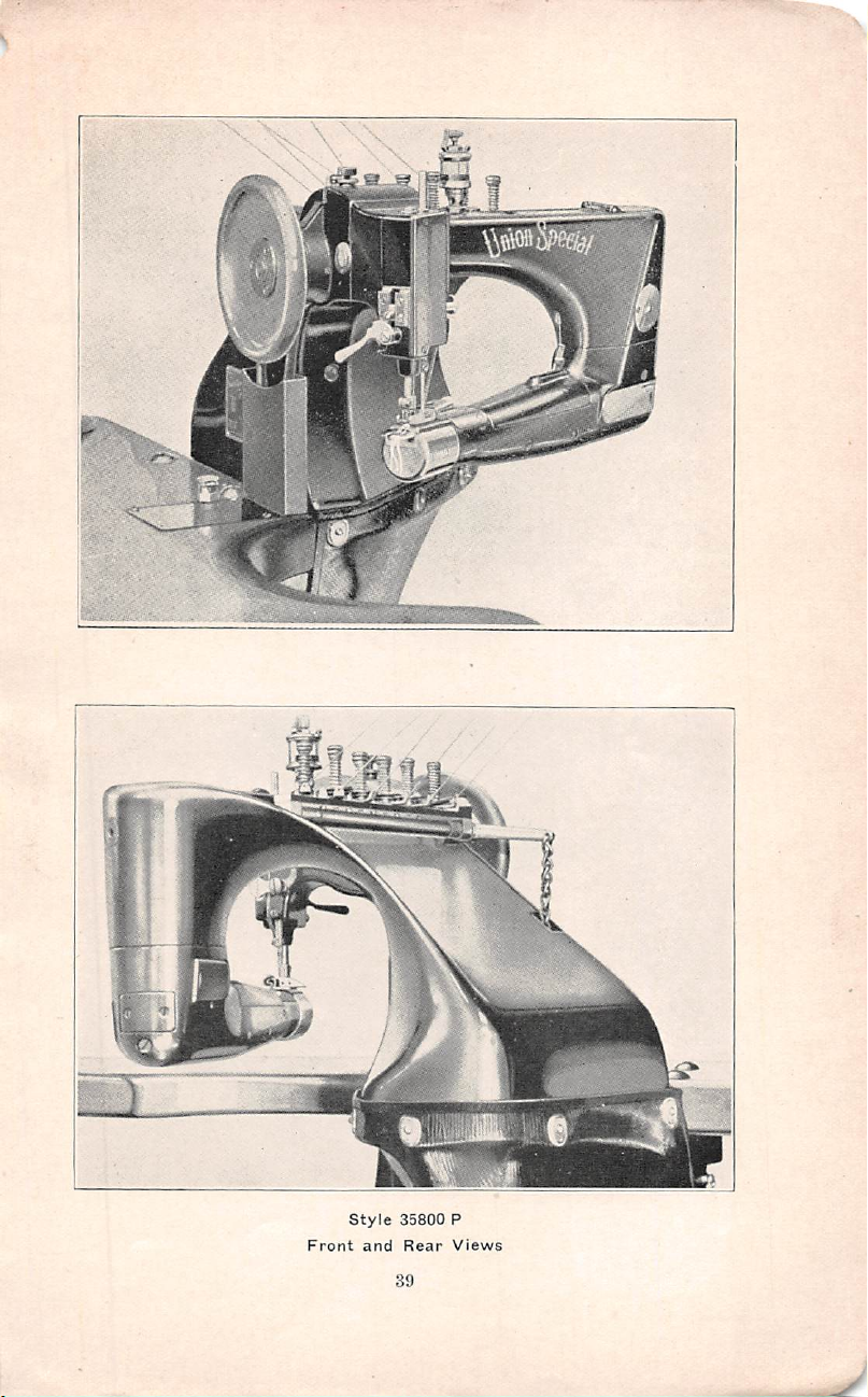
K
style
35800
P
Front
and
Rear
Views
39
Page 42

W;W
ii-
utility
Grinder
40
Page 43

DOUBLE
LOCKED
STITCH
y
Page 44

 Loading...