

Page 1
INDUSTRIAL
SEWING
FINEST
STYLES
20030
200
QUALITY
35
LEWIS
•
COLUMBI
a
MACHINES
(sc
‘
Ci)O)
I
,.
U
a
CATALOG
No.
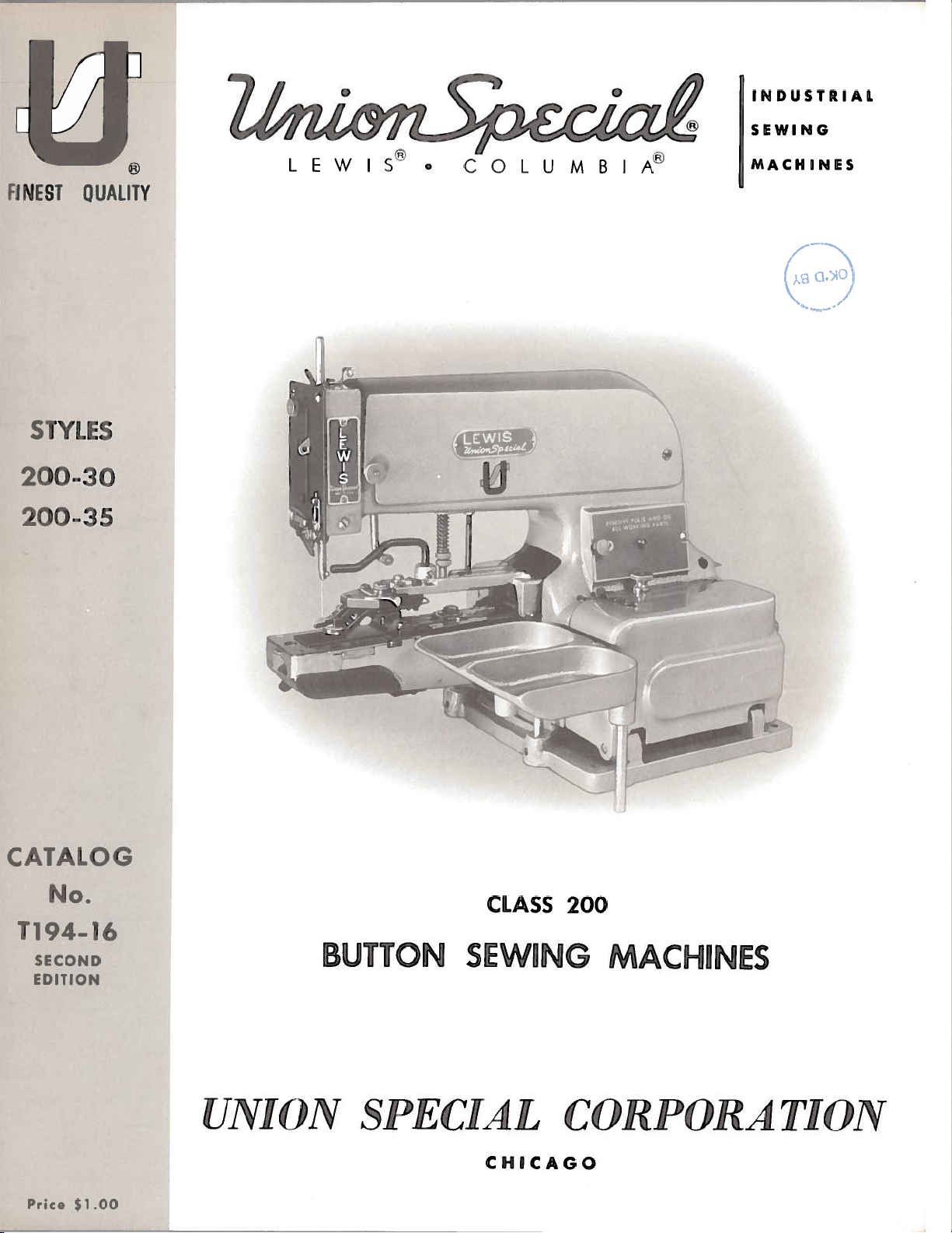
CLASS
T194-16
SECOND
EDITION
UNION
Price
$1
.00
BUTTON
SPECIAL
SEWING
CHICAGO
200
MACHINES
CORPORATION
Page 2
Catalog
No.
1194—16
(Supplernoni
AILJ
200-30
INST
TSTINC
LIST
lv
Styles
Catalog
IUCT
1
0
ANI)
OF
IONS
R
OPERATING
PA
RTS
No.
194-4)
200-35
Union
Rights
UNION
INDUSTRIAL
Second
Copyright
Special
Reserved
SPECIAL
Edition
1967
by
in
SEWING
CHICAGO
&
1969
Corporation
All
Countries
CORPORATION
MACHINES
S.
Printed
in
U.
2
A.
July,
1976
Page 3
ClasS
toward
1ach
01
The
UNION
machines,
sei’iu
hack.
the
I.
SPECIAL
i
in
lI)lNI’[l’[C’
1
’I’[0N
LEWIS
stnuped
is
iii
mr
of
in
(‘ad)
the
macli
machine
style
inc
is
01’
carries
plate
stamped
.Vl.P(ll[NlS
a
on
the
in
the
style
left
side
right
number,
of
side
the
of
which
arm.
he
in
cylinder
this
rlhiS
:iunction
lot’
all
in
this
number,
This
Reference
from
pulley
high
t;ypes
and
Aul;omatic
200-
production,
eyes,
30
stitches
Equipped
the
stitches
high
200-35
stitches
Equipped
cycle
Primarily
with
certain
Can
be
button
parts
catalog.
t;he
is
of
used
during
catah’g
herewith.
t
used
name
catalog
to
operator’s
away
flat.
two
and
stitching
Right
stitch
of
quality
Right
in
and
types
with
on
At
and
applies
direction
from
single
hole
for
in
two
with
cycle
two
garments
two
with
automatic
used
or
the
raising
is
a
Consu
styles
the
amount,
position
the
and
shank
cycle,
to
Left
hole
improved
(between
hole
Left
to
hole
improved
with
of
automatic
without
APPLICATION
supplement;
Ii.
catalog
200-
hack
of
required.
specilically
such
as
while
operator.
DESCRIPTION
thread,
four
hole
buttons.
cam
Stitching
a
or
trimming
the
buttons,
such
Stitching
buttons
trimming
button
heavy
the
of
the
:o
the
right,
button
Lever
drive
total
two
also
as
men’s
or
clamp
thread
button
automatic
clamp.
to
No.
and
book
to
seated
buttons.
with
Flat
of
of
rows
if
of
Flat
atotal
OV
catalog
tJl—
1
200-35
the
parts
the
Standard
left,
front,
at;
OF
sewing
Attachments
adjusted
stop
Buttons
parallel
16
mechanism
of
desired
sack
Buttons
of
16
mechanism
opener.
where
feeders
button
CA’I’A.[
No.
104—4
machine
4,
respectively
are
Style
back,
the
machine.
MACHINES
machines.
stitch
motion
With
stitches
for
parallel
at
the
coats,
suit
With
parallel
for
thread
and
for
clamp
OG
illustrated
range
clutch.
No
cutting
stitches)
end
coats,
a
cutting
cutter
use
and
styles
not
of
machine
or
up
Operating
Sews
available
Cross-
in
of
cycle.
Cross-
stitches
thread
is
with
opener,
should
illustrated
down,
all
to
sew
Single
four
thread
or
ladies
over
infour
needed.
necking
be
used
200—
10
or
and
listed
as
listed
etc.,
direction
popular
to
sew
snaps,
8
or
treadle
over
hole
at
in
the
Stitch.
buttons
the
end
Recommended
suits
Stitch.
holebuttons.
at
the
Recommended
attachment.
which
releases
and
described
are
sizes
16
stitches.
operation.
middle
and
end
in
200—
by
herein.
of
hooks
Sews
of
coats
Sews
of
stitch
con
15
part
given
the
and
8
only.
of
cycle
for
16
the
under
29
S-100/040
long,
Needle
diameter
29
29
29
29
The
recommended
Use
only
our
Needle
short
type
SHORT
S—090/036
S-100/040
S-110/044
S-125/049
brand
type
shank,
29
blade.
genuine
name
29
recommended
is
S-100/040
Other
speed
UNION
ZlnL,nE’pccaze
LSS-110!044
sharp
point
is
diameter
BLADE
INCHES
.036
.040
.044
.049
of
SPECIAL
for
needle
short,
a
these
is
recommended
Style
needles
DIA
MM.
.90
1.00
1.10
1.25
SPEED
machines
NEEDLES
LEWIS
200-35.
with
an
sharp
point
are
LONG
SHORT
29
29
29
29
29
3
1500
is
needles.
for
Needle
.044
inch
needlewith
available
with
SHANK
LSS—090/036
LSS-100/040
LSS-110/044
LSS—125/049
LSS-140/054
Style
as
P.
R.
The
type
(1.10
follows:
M.
needles
200-30
mm)
an
.040
BLADE
INCHES
and
29
LSS-110/044
diameter
inch
.036
.040
.044
.049
.054
are
packaged
needle
(1.00
DIA.
MM.
.90
1.00
1.10
1.25
1.40
type
is
blade.
mm)
a
Page 4
Selection
material
and
of
type
proper
of
button
needle
used.
NEEDLES
size
is
(Continued)
determined
by
size
of
thread,
weight
of
sample
read:
far
and
has
Page
on
starts.
seconds
fact
beneficial.
be
To
have
needle,
“100
When
as
it
will
that
set
A
cross
been
inserted
Immediately
To
thread
5.
These
Use
at
Most
they
of
are
needle
Needles,
changing
go,
screw
hole
machine,
machines
a
good
1000
the oiling
painted
orders
or
the
Type
the
with the
is
tightened
drilled
as
far
discard
should
grade
Fahrenheit.
places
red.
type
needle,
long
in
as
put
of
promptly
number
29
LSS-llO/044”
CHANGING
groove
securely.
the needle
it
will
any
needle
ThREADING
in
stop
oiled
be
straight
on
However,
make
the
and
should
to
bar
go.
which
position,
twice
mineral
machines
reference
sure
the
accurately
be
forwarded.
NEEDLES
that
front
can
also
may
AND
and
daily,
oil
are
to
filled,
it
is
inserted
and
the
be
used
have
a
OILING
thread
before
ofaSaybolt
readily
the
oiling
an
A
complete
spot
to
determine
hooked
in
accordance
the morning
viscosity
identifiable
diagram
empty
in
or
or
the
scarf
blunt
container,
order
needle
to the
point.
with
and
of
because
on
Page
if
the
afternoon
90
would
bar
rear,
needle
diagram
to
of
5,
will
a
as
125
the
Please
open
to
places.
Also
of
grease
pulley
The
shown
should
greasing
are
Tubes
Where
some
of
identification
Part
appear.
Important!
Which
Part
the
note
the
numbers
note
hinged
furnished
is
place
oiled.
of
grease
the
smaller
letter
is
that
base
that
there
removed,
be
construction
represent
All
On
Ordered.
it
is
may
parts,
is
stamped
will
covers
a
is
with
indicated
be
Orders,
be
necessary
and
tilt
label
the
machine,
the
grease
by
ordered
IDENTIFYING
permits,
and
on
in
to
the
same
Please
to
machine
on
the
pulleywhich
and
level
the
letter
under
each
part
those where
distinguish
part
Include
TERMS
remove
on
periodically,
checked
“A”
part
No.
PARTS
is
construction
the
regardless
Part
arm
its
side
in
the
28604
stamped
part
Name
reads
and
of
cover
to
reach
“Grease
the
replenished
diagram.
P.
with
from
the
and
and
plug
its
does
similar
catalog
Style
side
some
All
part
not
of
cover,
of
Here”.
screw
if
other
number.
permit,
ones.
in
which
Machine
the oiling
A
tube
in
required.
places
they
For
and
the
On
an
Prices
warded
directed.
F.
0.
A
B.
charge
cash
shipping
and
subject
point.
to
is
made
cover postage
Parcel
to
change
Post
without
shipments
and
insurance.
are
net
4
notice.
are
All
insured
shipments
unless
are
for
otherwise
Page 5

X
-l
--rn
111
Q;o
r
C)
z
rD
1
0
)
(1)
ro
o
C
z
C)
Page 6

IViost
200-15
additional
of
are
instructions
the
adjusting
applicable
SETTING
ASSE
MB
LING
instructions
for
Styles
required
THREAD
AND
200-30
for
ADJUSTING
in
Styles
PULL
Catalog
and
200-30
OFF
INSTRUCTIONS
No.
200-35
and
LEVER
194—4
respectively.
200-
35
(Style
for
arc
200
Styles
The
listed
30)
200—
new
as
10
and/or
follows:
and
Refer
ent;ered
tever
way
than
Cat.
to be
should
to
the
when
No.
repeated.
The
front
edge
The
the
in
operation.
screws
by
The
eighth
the
soon
so
accomplished
is
and
ing
visible
screws,
advance
Adjusting
increase
feed
the
194-4)
knives
knives
the
knives
as
the
the
the
to
plate
then
left,
of
the
cutter
stitch,
to
moving
time
cutting
machine
in
machine
is
should
slot
should
should
for
catch
adjusting
by
whenthe
of
pawl
Style
times
7
start
middle
the
is
changed,
have
in
SETTING
overlap
lever
be
cutting
the
machine
the
cut,
to
protrude
stroke
200—
and
to
move.
in
the
enough
casting
the
link
TIMING
set
loop
as
the
operating
moving
or
TIMING
10
has
of
the
stop
setting
SIDE
THE
just
adjust
THE
to
cut
the
cross
it
operating
is
the
a
cross
THE
except
risen
When
cycle,
position
of
PLAY
clearance
allow
to
OVERLAP
enough
knives
the
KNIVES
the
back
pulled
is
in
stop
pawl
pawl
greater
over
KNIVES
to
the
cam
IN
to
over
pawl,
position.
the
in
in
of
continue
top
the
Ibread
it
should
or
end
(B,
Fig.
KNIVES
between
free
movement.
OF
the
cut
for
the
(Style
thread
stitch.
to the
bottom
located
direction
opposite
the
distance
the
knives.
(Style 200-3
turning
of
pull
be
of
the
15,
THE
back
proper
200-30)
of
the
The
on
Loosen
from
pulley
travel,
its
off
lever
1/8
inch
cycle.
Cal
the
yoke
No.
slides
KNIVES
thread
cut,
triangle
knives
the
of
left
the
operating
the
of
rotation
direction acts
the
edge
Retighten
5)
the
has
further
If
link
of
the
which
after
should
button.
side
screws.
until
thread
moved
194-4)
insert
triangle.
is
of
of
of
needle
to
Fig.
(B,
will
determined
the
setting
not
move
This
left cam
the
pawl
the
cam
the
reverse.
the
cam
puii
all
the
have
and
can
attach
has
off
the
left
16,
the
The
of
too
be
will
will
The
of
the
This
(A,
nut
ward
adjusting
drive
which
(C)
ward
arm
have
nut
and
NOTE:
care
cutting
strike
(C),
ing
or
sewing
from
of
the
knives
stitch
last
can
be
Fig.
downward
or
stud
lever
(B,
will
repositioning
(D).
been
(A)
When
obtained,
securely.
While
must
be
knife
shoulder
the
either
at
closing
cycle,
needle
the
diagonal
should
before
accomplished
which
18)
repositioning
(A,
Fig.
Fig.
18)
permit
of
satisfactory
tighten
making
the
(E)
(B,
of
the
of
upper
as
to
its
knives.
in
taken
lever
end
of
the
slots
be
“Stop
will
or
forward
the
this
assure
Fig.
mounting
slots
knife
is
the
set
by
in
19)
loosen
knife
adjustment,
19)
possible
drive
to
cut
Position”.
loosening
permit
the
screws
or
drive
conditions
screws
that
does
screws
while
During
should
(D)
lever
the
up
of
the
knife
rear
link
(C)
the
not
open-
the
without
back
be
(B).
retracted
the
6
thread
knife
of
to
drive
the
Fig.
provide
pins
triangle
(F)
after
18
maximum
striking
setting
the
clearance
the
ends
Page 7

guide
When
(H)
the
should
culling
be
set
knife
to
TI1VIING
(A,
enter
L{ig
the
TilE
IKNIVES
20)
thread
begins
(All
it
t:riangle
Styles)
cutting
formed
stroke,
by
the
threads
wider
point:.
made
(C),
guide
tighten
as
portion
Adjustment
by
reposition thread
as
screws.
the
thread
spreading
they
of
loosening
required
slide
the
finger
of
up
looper
can
screws
finger
and
the
the
be
re
the
ing
front
the
The
clamping
If
adjustment
the
ing
move
drive
sooner
jaws
condition
place
(D).
block
knife
tripping
lever
wider
screw
acts
button
position
or
is
(B)
move
and
to
the
rearwill
the
reverse.
clamp
after
is necessary,
drive
link
block
to
actuate
tripping
for
alonger
obtained,
(H)
that
arm.
(K)
retighten
holds
Fig.
19
advance
Tighten
jaws
should
clearing
remove screw
Loosen
downwardly
trip
off
block
duration.
the
knife
screws
return
the
and
closing
upwardly
screw
drive
the
sewn
screw
in
When
(J)
time
(H)
the
to open
desired
and
link
of
(F).
to
button.
secur
(J)
knife
of
jaws
arm
jaw
the
and
re
BUTTON CLAMP
The
should
ing
Fig.
the
be
button
13)
begins
can
be
screws
front
opening
tripping
and
--
(St:yle
button
set
200-35)
clamp
to
clamp jaws
before
just
to
lift. Adjustment
made
(F)
by
and
block
moving
--
the
OPENER
opener
start open
the
clamp
loosening
moving
Mov
(G).
block
(E,
the
to
NOTE:
reposition
do
not
In
1/32
inch
Thread
bushing
last
tying
6
in
Catalog
Turn
face
the
glazed
or
of
the
ance
between
passage
paragraph
To
come
using
or
of
knives.
of
disengage
tripping
in
contact.
various
to
1/64
take-up
slot
stitch
No.
the
nipper
the
nipper.
thread
For
the
the
thread
for
thet1THREAD
blocks
inch
in
face
out of
194-4.
and
cutting
nipper
button
threads
with
should
plate,
the
block
This
helps
during the
clamp
(Gand
K,
ADJUSTING
it
may
reference
ADJUSTING
be
set
as
to
assist
way
of
the
THREAD
that
so
provides
draw
most
and
threads
the
up
nipper
sewing
NIPPERH
opener,
Fig.
become
high
cutting
one
a
more
the
18)
STOP
Fig.
to
THREAD
as
possible
in
drawing
NIPPER
of
its
positive
last
tying
it
is
block
cycle.
on
page
7
merely
so
they
MOTION
necessary
2
in
TAKE-UP
knife
two
stitch
necessary
to
Refer
15,
Catalog
without
up
and
micro-
nipping
1/64
both
the
its
to
to
to
finger
serrated
loop
inch
in
change
No.
striking
cast
action
before
change
or
Fig.
Catalog
Fig.
the
194-4.
off
guide.
the
just
12
20
dimension
upper needle
thread
Refer
faces
when
the
will
using
cutting
3/64
enough
on
page
No.
194-4.
loop
inch
13
to
contact
smooth
action
clear
for
and
from
of
Fig.
free
bar
the
the
Page 8

4
a
if/
‘7-’
1
8
Page 9

pa
‘the
used
are
200—15
illust
it
s
hot
on
respectively.
rat
h
id
Styles
on
200—30
pages
tt
and
and
200—35
10,
aix!
(unless
(IC
seethed
otherwise
on
this
specified),
page
and
page
hut
not
11
repre
used
on
sent
Styles
lie
200—10
part
I
tat
s
antI
Catalog
Use
this
in
Reference
indicate
NO’lIi:
Ref.
No.
1
2
3
4
5
6
7
8
9
10
11
12
13
14
15
16
17
18
19
20
21
22
23
24
25
26
27
28
*
*
*
29
30
31
32
33
34
35
36
37
38
39
40
41
42
43
44
45
46
47
48
49
*
*
*
catalog.
numbers
they
‘I’lte
Part
No,
430—63—7
99-353
80265
21-440
115-169
22894
71-119
40-3ht
22542
1731
166-14
99—316
1189
22-205
21-337
45-347
45-346
21-336
45-332
158-11
157-10
18-945
18-931
21-315
18-272
18-873
1005
71—112
18-929
18-930
20-123
17-178
CS337
45-481
40
22596
45-477-1
122-29
45-482
51170
815
115-168
94
18-1089
4119-84
4119-86
75-253
22564
22542
46-204
CS337
46-203
14-365
71-122
20-45
No.
are
part
W
L
L
L
C-615
D
L
F
194—4
(Styles
that
component
descriptions
A
are
Rutton
Knife
Screw,
Knife
Washer,
Screw,
Button
Looper
Knife
Nut,
Washer,
Knife
Screw,
Screw,
Knife,
Knife,
Screw,
Knife
Screw,
Knife
Stop
Button
Nut,
200—10
inside
part.s
below
l3utton
Thrust
Spring,
Push
Push
Washer,
Screw,
Screw,
Button
J:lolder
Screw,
Pin,
Left
Left
Right
Right
Adjusting
Slide
Spacer,
Adjusting
Screw,
Spring,
Screw,
Screw,
Screw,
Lifting
Screw,
Guide
Lock
Drive
Driving
Activating
for
Clamp
Finger
Screw
Driving
Driving
Motion
for
bracket
a
a
of
are
Clamp
Clamp
Washer,
Rod
Screw
Rod
for
for
Clamp
for
for
Spring,
Lever
Lever
Spring,
in
for
for
for
for
Rod
for
Screw,
Nut,
Lever
No,
for
for
No.
for
Clamp
Positioning
No.
for
for
No.
No,
for
upper,
lower,
Guide
No,
for
No,
for
Clamp
button
and
complete
for
Assembly
No,
for
Tripping
for
No,
No,
Nos,
Nos.
Lever
Holder
for
Screw
No,
No,
for
No,
No,
No,
Nos,
for
46-203
Lever
No.
45-481
Lifting
17-178
No,
Tripping
115-168
45-482
complete
complete,
46-204
Link
46-203
Link
frip
Lifting
clamp
200—15
or
Style
Holder
for
71-119
No,
166-14
45-332
Pawl
21-336,
for
for
No,
99-316
158-11
99-316
99-316
71-112
for
No,
Adjusting
22596
Finger,
Lever,
knife
17-178
Arm
Lever
respectively)
box
part
200-35
No.
Bloel
18-873
21-336,
45-347
No,
No,
18-945
45-346,
Nos,
158-il
knife
screw
knife
Lever
for
knife
Block
knife
knife
with
for
knife
knife
Shaft
Rod
lifting
the
on
or
71-119
push
serex
button
adjusting
21-337
45-346
adjusting
holder
slide
holde
holde
lifting
45-346,
Stud
drivinglink
driving
for
Styles
drive
activating
pin,
Styles
driving
driving
rod
picture
assembly.
only,
Description
rod
clamp
21-337
right
left
right
in
rod
45-347
slide
Styles
200-30,
lever
drive
clamp
for
200-30,
for
unless
push
lever
right
lever
lever
screw
holder
right
45-347
holder
in
lever
200-30,
adjusting
lever
tripping
lever
Styles
link
link
all
plates
rod
pawl
and
and
and
arm
200-35
adjusting
arm
parts
and
otherwise
left
left
left
right
200-35
block
200-30,
200-35
spring
and
stud
not
have
spring
lever
left
stud
200-35
illustrated
indented
specified,
lever
described
or
descriptions
Arnt
Req
1
1
1
1
1
2
1
2
1
1
1
1
2
2
1
I
1
1
1
1
1
1
1
1
1
2
1
1
2
2
1
1
1
1
4
2
1
1
1
1
I
1
1
2
1
1
1
2
1
1
2
1
1
1
2
*
shown
Not
on
picture
plate.
9
Page 10

N
a
0t
Page 11

No.
I
(lot
ar
No.
l)ot
It
Styles
200—
JVliS(
30
and
IIA
200-35,
N
IX)
IS
I
I
tin
I)escript
A
ess
tTS
otherwise
ion
specified.)
Req
10
11
12
13
14
No.
166—13
30
onty
Operating
set
large,
22538
1
Screw,
fot
166—13
31--
93
Thread
Cain,
two
4
5
122—29
110-213
A
I
ooper
A
Spacer
for
Style
(titter
for
No.
Positioning
Plate,
200
vibrating
13-984
plate
6
7
3
45-482
1039
13—
21-163
Knife
Screw,
Spring,
Activating
for
No.
for
Lever
45-482
thread
only
9
46—205
Thread
Cutting
Knife
only
No.
22542
4119-84
4119-86
22564
F
75-253
Screw,
for
Knife,
Knife,
for
Style
200-30
upper,
lower, complete
Screw
Finger
46-205
only
complete
Guide
button
screws
Finger
to
cutting
Lever
thread
Pawl,
plate
raise
knife
thread
with
activating
lever
Link,
pin
cutter
for
lengthwise,
No.
110-302
link,
for
cutting
operating
Style
for
Style
knife
200—30
lever
Style
includes
needle
200—30
lever
pawl,
only————
200-30
link,
4
2
1
1
1
1
2
1
1
1
1
1
2
1
ii
Page 12

btE
Se
WORLD’S
ATLANTA,
BOSTON,
CHICAGO,
DALLAS,
LOS
FINEST
‘NCE
UNION
facilities
aid
equipment
Special
tory
promptly
tion,
serve
ANGELES,
QUALITY
*
SPECIAL
throughout
in
you
the
for
representatives
trained and
and
there
isaUnion
you.
Check
GA.
MASS.
ILL.
TEXAS
CAL.
INDUSTRIAL
maintains
the
world.
selection
your
particular operation.
are
efficiently.
and
able
of
service
to
Whatever
Special
with
him
today.
MONTREAL,
TORONTO,
LEICESTER,
LONDON,
SEWING
soles
and
These
offices
the
right
men
serve
your
your
Representative
BRUSSELS,
MACHINES
service
will
sewing
Union
are
fac
needs
loca
to
CANADA
CANADA
BELGIUM
ENGLAND
ENGLAND
NEW
YORK,
PHILADELPHIA,
UNION
400
N.
N.
PA.
Representatives
industrial
SPECIAL
FRANKLIN
Y.
cities
and
distributors
throughout
ST.,
PARIS,
STUTTGART,
in
the
all
world.
FRANCE
GERMANY
important
CORPORATION
CHICAGO,
ILL.
60610
 Loading...