

Page 1
INDUSTRIAL
SEWING
S
20
TYLE
0-2
C 0 L U M B I A®
MACHINES
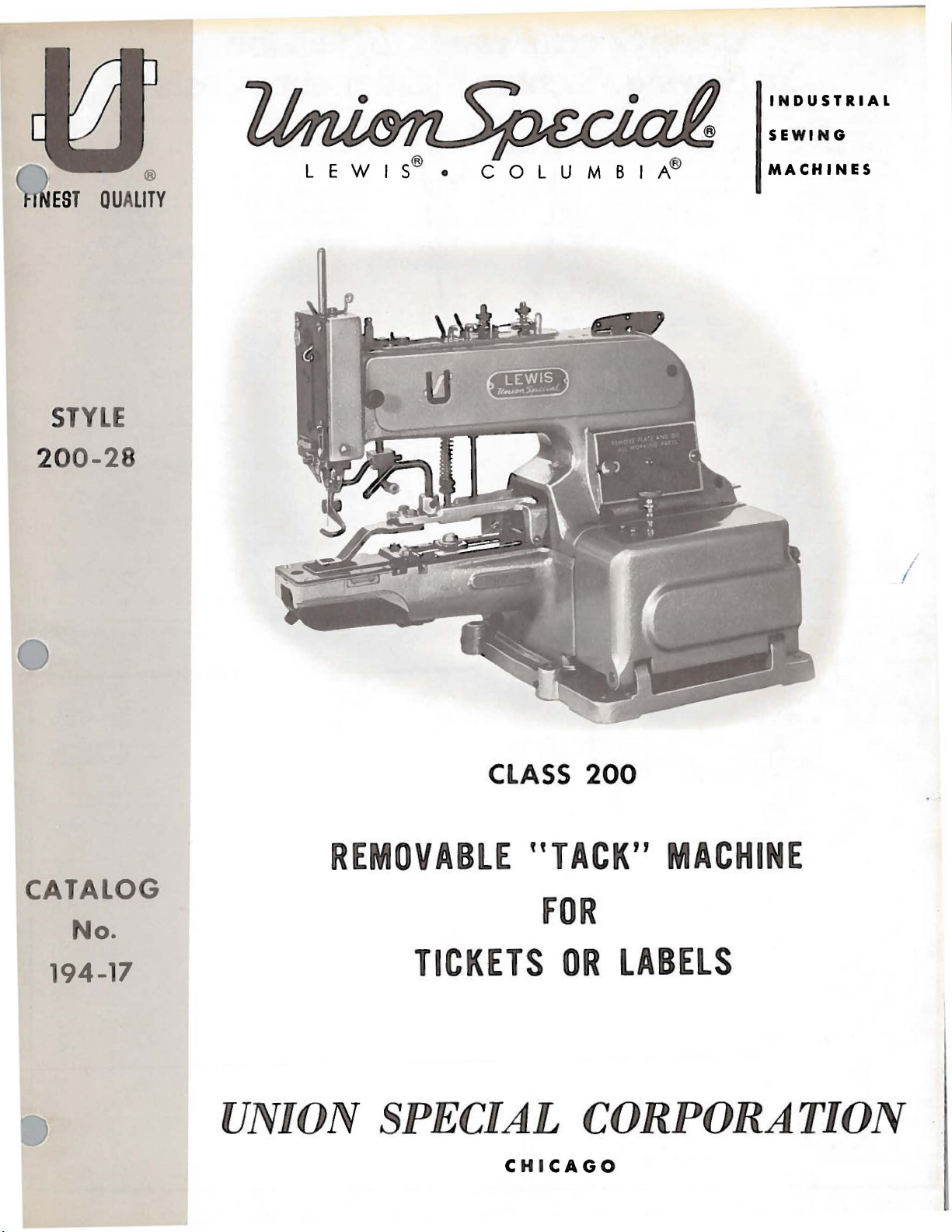
CLASS
REMOVABLE
CATALOG
"TACK"
FOR
No.
194-17
TICKETS
OR
UNION SPECIAL
CHICAGO
200
MACHINE
LABELS
CORPORATION
Page 2
Union Special is offering two practical systems to help pinpoint and
reduce
your
system to help spot machines requiring
and a parts inventory system to speed routine repairs.
Machine Maintenance Records
Repair-prone machines
up
your maintenance dollars in short order. To help spot the
Union Special suggests two variations
record keeping system using cards provided by Union
The first system utilizes a
(Form
required, the card is
and their cost are entered in the spaces provided and the card is refiled.
The second system is normally used when more detailed information
on repair costs is desired . Two record cards are used: a
Request Card
233). When a machine requires service, the fore lady
out the
fills in the time the repair work is started, the parts used and their cost,
sewing machine maintenance costs: a record keeping
or
inexperienced competent operators can eat
..
237)
I>Afl
for
each sewing machine in a plant. When a repair is
pulled
MA-~IISNUOI.
:
. , ..
-.~
Machine Maintenance Record
from
MAC:HINK MAINU .NA
.,.
....
I I I I
.... ,\1 ...
fO\tt'\
Recotd . -
~"""'\••
-
-
---
..
(Form
234), and a
top
of a ..
Repair Request Card
abnormally high maintenance,
of
a simple maintenance
the file and the repair date, parts used,
NCC RECORD
..,,.,..,o.,,
_,
-·
~::L
~3~
.
fl\11'~'
AlllloA~NG
•
... -.,. •
.,.
ul.a»
-
-
te~>a~'
c
e
~
lf
-
--
-
-
-
..
Machine
Repa
ir Record
..
and gives it to a mechanic. He
or
se
problems,
Special.
..
card
••n~oo
-·
~
1-
~
~$
..
Repair
..
(Form
foreman fills
and the completi
..
Machine Repair Record
Whichever system is used, management now has an invaluable tool
to reduce needless maintenance costs.
Part
Repair
While record keeping tells management which machines requ ire
abnormally high maintenance, it does little to help reduce the
caused by routine repairs. To alleviate this situation,
recommends that manufacturers establish a formal parts
system for each type
Excessi
be e
li
minated with an orderly in-plant inventory
needed parts. There is
for spare parts.
downtime is
when the overall savings are considered.
-
- ·
=
=-
-~
-1--
For free sample
inventory
local Union Speci
on
time. This data is then transferred to the per
..
kept in the office.
Inventories
of
ve
machine
Long
kept
MACHIN£
REPAIR
111••
11••
H"'"•
C
_
,.
..
~
-
fi>IICI;\\~
fO~
lists
for
sewing machine they operate.
downt
ime and wasted hours
no
longer a need to cannibalize
waits for deliveries are avoided and machine
to a minimum. The cost
RECORD
CARD
:
:.:
~
.
..::~
1-
{'1\
eRe
__
cop1es
a variety
al
Representative
m
~
...
WI"
·
-
'2.33-
9'11
catd "-
6
----
--
-
of
the machine record cards and spare part
of
the most popular machines, contact
u ...
I
.......
......
I
--
O" u '
1 .
,-:w
~·
=
-
. . \l.eques
- Ri
1!
1'UUCIOM"'UI.II
... c.t ....
or writ
Union
inventory
by
mechanics can
of
the most
other
of
a parts inventory is small
.....
.
RE
PAIR REQU
EST
-
PA
RH US&D
~···-·-
-
__ ...
CARD
-·
z3A-
t
catd
-~
-~-
__
Union
...
_.
....
.
,..
_
···
· ~
..
• NO
-_
fO\tt'\
'i>a't
Mir.
. l#IIIIC:O
c, ..,
- -···-·--·--
e direct to
man
downtime
Special
commonly
machines
-
:!.__
-
-
-
~
=
-
=
=
-
SpeciaL
nt
your
u
1
111111 ""'"
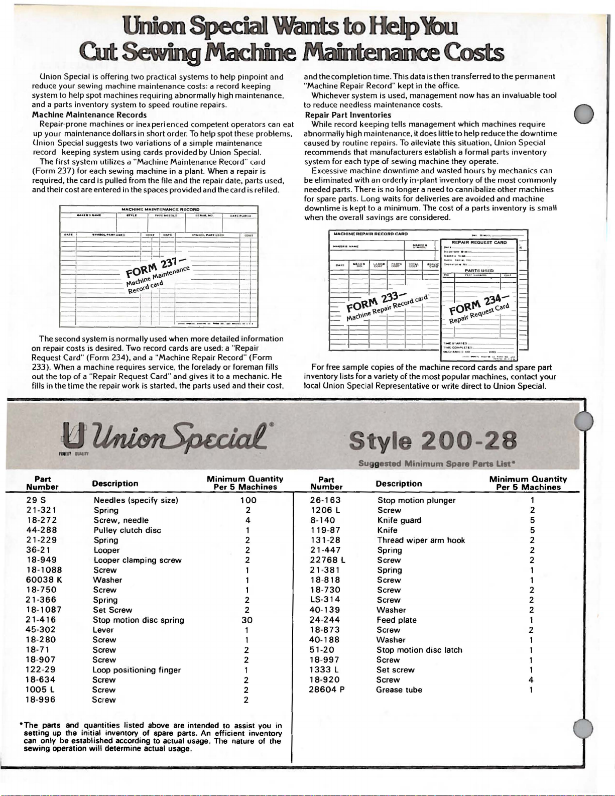
Part
Number
29
s
21-321
18
-2 7 2
44-288
21-229
36-21
18-949
18-1088
60038
18-750
21 18-1087
21-416
45·302
18-280
18
18-907
122-29
18-634
1005
18-996
*The
setting up the initial inventory
can
sewing operation
K
366
-71
L
parts and quan
only be established according to actual usage. The nature
Description
Needles
Spri
Screw,
Pulley clutch
Spring
Looper
Looper clamping
Screw
Washer
Screw
Spring
Set
Stop
Lever
Screw
Screw
Screw
Loop posi
Screw
Screw
Scr
will
(specify size)
ng
needle
disc
screw
Screw
motion
disc
spring
tion
ing
finger
ew
titie
s listed above are intended to assist you in
of
spare parts. An efficient inventory
determine actual usage.
Minimum
Per 5 Machines
Quantity
100
2
4
1
2
2
2
1
1
1
2
2
30
1
1
2
2
1
2
2
2
of
the
Part
Number
26-163
1206
8-
140
119-87
131-28
21 -
447
22768
21-381
18-818
18-730
LS
-3
14
40-139
24-244
18-873
40-188
20
51 -
18-997
1333
18-920
28604
tyle
Description
L
L
L
p
Stop
Screw
Kni
fe
Knife
Thread w i
Spr
ing
Screw
Spring
Screw
Screw
Screw
Washer
Feed
Screw
Washer
Stop
Screw
Set
Screw
Grease
200-28
Minimum
Per 5 Machines
mot
ion
plunger
guard 5
per
arm hook 2
plate
motion
disc
latch
screw
tube
Quantity
1
2
5
2
2
1
1
2
2
2
1
2
1
1
1
4
Page 3
(Supplement
Catalog
INSTRUCTIONS
to
No.
Catalog
FOR
194-17
No.
194-4)
ADJUSTING
Union
Rights
LIST
CLASS
Style
First
Copyright
Special
Reserved
AND
OF
200-28
Edition
by
in
OPERATING
PARTS
200
1972
Corporation
All
Countries
UNION SPECIAL CORPORATION
INDUSTRIAl
Printed
•
May,1976
SEWING
CHICAGO
in
U.S.
3
MACHINES
A.
Page 4
IDENTIFICATION
OF
MACHINES
Each
class
of
machines~
The
toward
the
This
junction
200-1
a
reference
therewith.
are
description
illustrated
a
bracket
description
number
when
in
ordering
The
It
can
also
References
operator's
is
away
from
UNION
serial
back.
catalog
illustrated
number
and
on
the
or
box.
under
the
second
repair
catalog
be
to
direction,
position
the
SPECIAL
is
stamped
number
of
each
is a supplement
Only
amount
picture
On
the
those
and
listed
and
this
required.
plate
the
copy
description
column~
parts.
applies
applied
specifically
with
such
while
seated
operator.
LEWIS
in
machine
the
style
machine
APPLICATION
to
Catalog
parts
reference
at
by
which
the
back
number
Any
having
part
page a component
of
the
assembly
never
discretion
as
use
to
the
to
right~
at
the
machine.
carries
plate
is
stamped
OF
CATALOG
No.
are
used
of
this
is
that
the
reference
the
reference
Standard
other
left~
front~
a
style
on
the
left
side
in
the
right
194-4
book.
then
on
used
and
Style
The
to
200-28,
is a component
number
part
or
is
base
indicated
part.
number
Style
Styles
back,
machine
of
machines
etc.,
Operating
number~
of
the
side
of
should
be
but
parts
obtain
are
the
of
another
or
numbers
by
Always
in
the
as
in
are
given
direction
which
arm.
the
cylind
used
not
in
on
identified
part
number,
indenting
use
the
first
listed
column
herein.
this
from
of
the
in
this
con-
Style
part
inside
part
class.
the
pulley
er
by
is
its
200-28
Removable
"Tack"
Equipped
tack~
Type
These
starts.
seconds
Most
fact
they
be
beneficial.
Please
to
open
oiling
Also
of
grease
should
ing
place
oiled.
High
with
with
after
29S-100/040
machines
Use a good
at
1000
of
the
are
painted
note
the
hinged
places.
note
that
is
furnished
be
removed,
is
indicated
Production~
Tacks.
a
1/8
thread
the
sewing
Single
Sews
inch
protruding
wiperwhich
cycle.
needle.
should
grade
be
of
straight
Fahrenheit.
oiling
that
places
red.
it
base
there
with
the
by
on
However,
will
be
covers
is a label
the
grease
the
letter
STYLE
Needle,
eight
stitches
Equipped
Maximum
oiled
twice
mineral
the
machines
reference
necessary
and
tilt
on
machine
level
checked
"A"
OF
MACHINE
Single
tail
pulls
the
recommended
OILING
daily,
to
machine
the
pulley
and
periodically
and
in
the
right
permitting
severed
to
sew
before
oil
of a Saybolt
are
readily
to
the
remove
on
which
replenished
diagram.
Thread
to
left
thread
up
speed
oiling
arm
its
reads
the
All
Machine
for
stitching
easy
removal
tail
to
1/4
inch
1500
the
morning
viscosity
identifiable
diagram
cover
side
to
and
reach
"Grease
plug
screw
if
required.
other
for
free
wide
R.
P.M.
and
because
Fig.
side
Here".
places
Stitching
a
of
of
the
afternoon
of
90
cover
some
in
the
The
shown
two
hole
'Tack".
sewn
'Tack".
to
of
11,
will
of
A
tube
pulley
greas-
125
the
and
the
are
Tubes
of
grease
may
be
ordered
under
part
No.
4
28604
P.
Page 5
word
Use
only
"LEWIS
Renuine
on
the
UNION
shank.
NEEDLES
SPECIAL
LEWIS
needles.
They
are
stamped
with
the
Unless
sewed
off
and
with a sharp
Selection
weight
sample
read:
as
tighten
has
To
When
it
will
A
been
of
have
needle.
''1.00
go,
set
cross
inserted
material.
changing
Immediately
instructions
shipped
point
of
and
the
needle
or
Needles.
with
the
screw
hole
securely.
drilled
as
discard
with
has
proper
orders
the
type
Type
the
long
far
to
the
contrary
needle
a .
040
needle
promptly
number
29S-100/040".
CHANGING
needle.
make
groove
in
the
needle
as
it
will
any
needle
are
Type
inch
29S-100/040.
(1.
02
size
is
and
should
determined
accurately
be
NEEDLES
sure
to
the
bar
that
front
can
go.
which
may
THREADING
received.
This
mm)
diameter
forwarded.
it
is
inserted
and
the
also
be
used
have a hooked
machine
needle
blade.
by
the
filled,an
A
spot
or
to
Style
is a short
size
of
empty
complete
in
the
needle
scarf
determine
or
blunt
200-28
thread
container.
order
bar
to
the
if
the
point.
will
needle.
and
would
as
rear
needle
be
the
a
far
and
To
thread
diagram
CAUTION!
operations
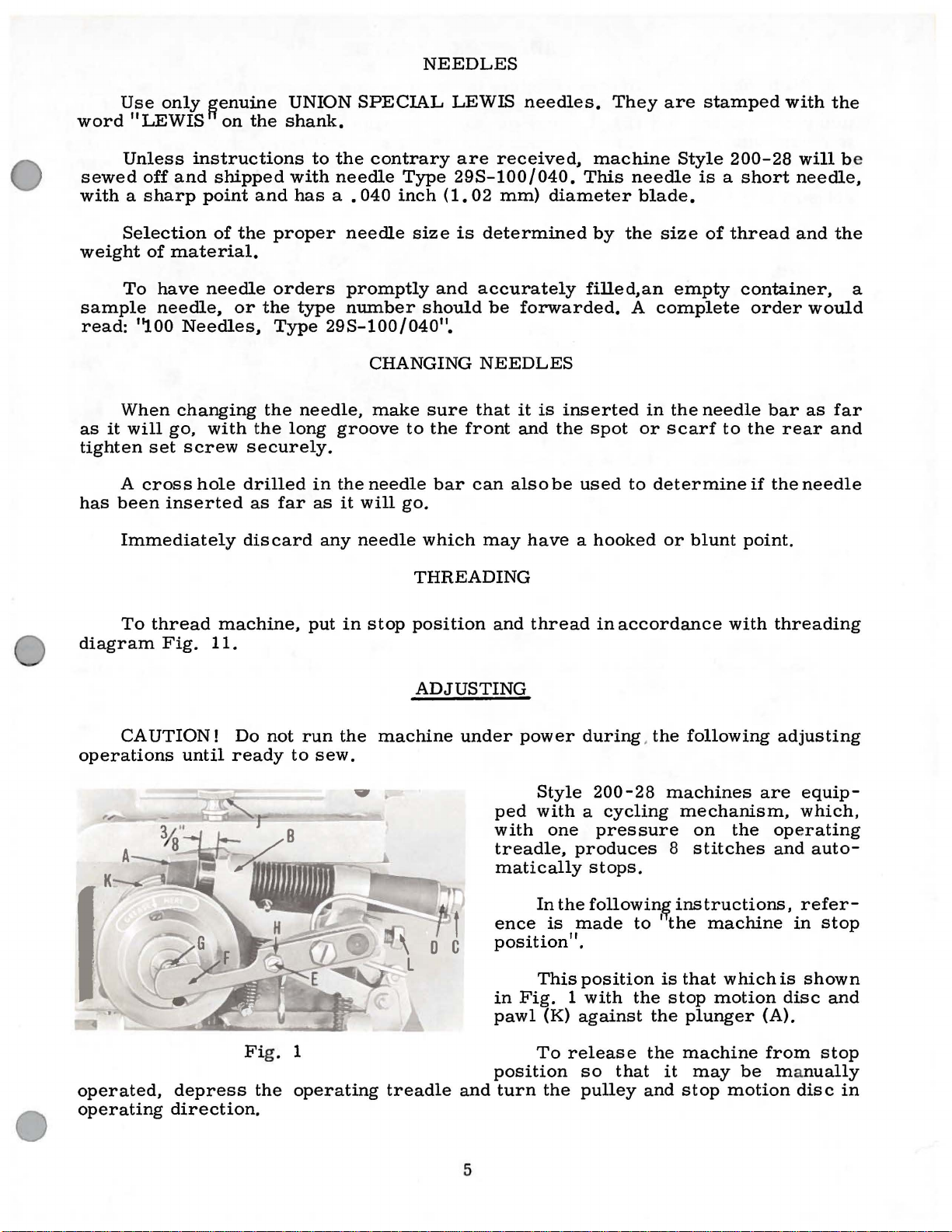
operated,
operating
machine,
Fig.
11.
until
depress
direction.
Do
not
ready
Fi
g.
the
put
in
run
the
to
sew.
1
operating
stop
position
ADJUSTING
machine
treadle
and
under
ped
with
treadle,
matically
ence
position".
in
pawl
position
and
thread
power
Style
with a cycling
one
produces
In
the
is
made
This
Fig. 1 with
(K)
against
To
release
turn
the
in
accordance
during. the
200-28
following
machines
mechanism,
pressure
8
stops.
followin~
instructions,
to ' the
position
so
pulley
the
that
is
the
the
it
and
that
stop
plunger
machine
stop
with
on
the
stitches
machine
which
motion
may
be
motion
threading
adjusting
are
equip-
which,
operating
and
auto-
refer-
in
is
shown
disc
(A).
from
ma
nually
disc
stop
and
stop
in
5
Page 6

ADJUSTING
CLUTCH
With
set
so
plunger
to
obtain
there
the
set
is
pulley
screw
ADJUSTING
With
loosen
(A,
Fig.
rotate
ance
in
cam
between
cam.
Depress
ine
out
of
two
complete
direction.
ure
distance
3)
and
highest
This
trip
lever
it
be
necessary
the
that
there
lever
this
1/32
is
pressed
(L)
the
the
two
2)
in
to
roller
stop
Release
adjustment
and
machine
is
brack
et
setting.
inch
is
securely
clearance
STOP
machine
socket
stop
motion
secure
(C)
the
treadle
position
revolutions
treadle
between
point
on
moving
to
move
in
3/8
inch
(B).
Lock
in
towards
MOTION
in
head
1/32
and
to
and
plunger
disc
is
made
lever
lever
stop
position,
clearance
Loos
the
between
tightened.
stop
position,
set
screws
cam
(B)
inch
front
take
rotate
in
operating
and
(A,
(B).
by
up
down,
en the
back
nut.
ball
machine.
and
clearof
slot
mach-
pulley
meas-
Fig.
The
distance
loosening
or
down
depress
the
stop
between
back
Adjust
(G)
Lock
clamp
to
secure
lock
and
should
the
motion
the
nut
(C)
screw
the
screw
screw
the
treadle
plunger
bottom
and
(E)
thin
with
be
3/32
(D,
3/32
while
(A,
of
the
adjust
in
cam
section
nut
(H).
Fig.
inch.
Fig.
inch
Fig.
plunger
the
lever
of
lever
Make
2
2)
in
clearance.
making
1)
should
and
front
(F)
so
(F)
nut
when
sure
stop
motion
Should
adjustment.
be
the
(D)
that
that
Loosen
lines
(C)
ly.
The
machine
link.
the
on
cams
tacking
in
stop
Fig.
two
screws
with
clamp
position,
3
(B)
and
timing
pins
ADJUSTING
lifting
the
link
lip
turn
cams
(D)
in
bed.
CLAMP
(E, Fig. 4)
on
the
fork
Depress
out
of
stop
two
complete
direction.
Fig.
until
1)
Turn
first
and
pulley
screws
coming into
loosen
turn
machine
screws
(A)
Retighten
LIFTING
is
lev
these
pulley
in
in
proper
er
(F)
is
(B)
either
all
LINK
is engag
TIMING
treadle
position
revolutions
Loosen
lay
machine
in
view
two
in
operating
again
are
in
direction
four
position,
CAMS
to
and
knurled
operating
in
cams
are
screws.
in
stop
view.
cam
screws
ed
in
take
machine
rotate
in
operating
screw
on
its
direction
(A,
accessible
Continue
direction
position
to
align
secure-
when,
the
with
slot
pulley
side.
Fig.
and
until
and
timing
the
of
the
(J,
4)
to
clamp
Forward
screw
and
(G)
backward
in
lever
adjustment
(H)
and
moving
of
lever
6
the
on
link
shaft.
is
accomplished
by
loosening
Page 7

ADJUSTING
CLAMP
LIFTING
LINK
(Continued)
Adjustment
moving
rest
against
fork
lever
the
of
the
on
Fig.
needle
fork
shaft.
4
bar
lever
clamp.
(F)
is
made
by
loosening
the
needle
middle
long
tion
volutions
position,
of
timing
ing
on
should
the
loosen
and
bar
screws.
screws
ADJUSTING
When
upper
needles,
Take
and
With
needle
To
take-up
to
pair
bar;
pair
machine
turn
in
the
the
lines
which
be
even
raise
needle
desired
The
using
for
of
operating
length
bar
clamp
short
of
timing
long
timing
use
pulley
needle
upper
(A,
with
bushing.
or
lower
bar
height
take-up
in
collars
NEEDLE
needles,
lines
needles,
lines;
the
lower
out
of
two
complete
direction.
bar
in
line
of
Fig.
of
the
clamp
screw
5),
needle
lower
needle
and
clamp
(J)
BAR
on
use
for
extra
pair.
stop
posi-
its
lowest
each
dependis
used,
edge
screw
(C),
move
retighten
must
and
use
the
the
re-
pair
of
bar,
(B)
The
needle
dle
set
screw
ing
freely.
The
position
gauge
the
(Fig.
that
its
moving
feed
done
to
at
the
machinedsurface
5).
Make
it
does
travel.
Adjustment
feed
NOTE:
plate
for
clarity
make
the
bar
is
(D)
enters
of
factory.
ALIGNING
sure
that
not
interfere
is
made
plate
TIMING
Fig. 7 shows
and
adjustments.
to
desired
NEEDLE
tacking
only.
correctly
the
the
needle
The
distance
of
the
FEED
the
feed
by
clamp
These
slot
cylinder
plate
with
the
loosening
position.
WITH
the
machine
removed.
parts
positioned
in
the
needle
bar
bushing
from
PLATE
needle
baseis
(A,
two
HOOK
need
its
Fig.
with
when
lower
3
6)
at
any
screws
needle
This
not
be
the
nee-
bar
bush-
is
set
to
edge
1/32inches
is
set
point
(B)
and
plate,
has
been
removed
to
so
of
a
Fig.
5
7
Page 8

TIMING
NEEDLE
WITH
HOOK
(Continued)
Take
operating
raise
pair
it
of
equipped
machine
direction.
until
the
timing
with
out
of
stop
Lower
lower
lines
on
edge
the
long needles,
position
the
needle
of
the
bar
use
needle
when
the
and
bar
Fig.
using
lower
rotate
until
6
bar
short
pair
pulley
it
reaches
bushing
needles.
of
timing
two
is
midway
lines).
complete
its
lowest
(When
revolutions
position,
between
the
then,
the
upper
machine
in
is
proper
the
screws
Rotate
bar
is
that
the
both
(G)
so
and
retighten
that
its
in
cam,
ting
direction
(B,
Fig.
inch
clearance
even
point
screws
that
there
timing
making
7)
between
in
the
the
pulley
with
of
(A)
hook cla
line
sure
until
in
the
it
and
Fig.
between
cam
the
lower
the
hook
in
the
is
the
coincides
the
direction
the
7
the
and
slide
in
operating
edge
is
sleeve.
smallest
mp
screw.
that
the
needle
needle.
loop
the
of
at
the
Loosen
amount
Loosen
with
cam
bar
of
the
Retighten
positioning
sleeve
direction
the
needle
center
hook
of
set
the
timing
is
against
is
at
its
needle
Loosen
Fig.
7)
ward.
loop
positioning
finger
slightest
finger
inch.
To
screws
sleeve
the
screws
sliding
loosen
in
the
finger
back
until
bar
of
the
collar
clearance
screw
line
the
lowest
until
clamp
needle
and
Insert
forward.
amount
and
needle,
make
(A,
Fig.
forward
enough
on
the
screws
direction
and
so
that
the
lower
bushing.
needle
clamp
between
(C)
on
the
sleeve.
position
there
is a clearance
screw
slide
a
screwdriver
finger
There
of
this
8)
slightly
shaft
(C)
in
necessary
the
it
contacts
timing
Rotate
on
the
screw
in
cam
sleeve
Turn
and
(A)
securely.
guard
clamp
needle
(C)
should
clearance
approximately
adjustment,
in
the
sleeve
and
to
prevent
during
adjustment.
cam
(D)
needle.
the
line
the
back
side
(E)
its
point
(D)
and
(F).
the
pulley
slide
the
screw
guard
behind
and
be
between
loosen
(B),
retighten
the
and
slide
to
secure
Tighten
cam.
on
the
sleeve
and
and
slide
and
the
rotate
Tighten
in
needle
of
about . 002
(B)
for-
pull
only
.
slide
one
sleeve
Now,
cam
one
needle
(B)
tighten
hook
needle
cam
screws
opera-
guard
(A,
the
the
the
the
002
set
of
the
of
so
so
8
Page 9

HEIGHT
OF
TACKING
CLAMP
With
tacking
adjustment,
stop
the
tween
Height
has
clamp
Return
pin
(F,
needle
the
of
been
the
machine
to
loosen
the
machine
Fig.
will
not
stop
pin
stop
pin
obtained,
the
Fig.
6).
strike
and
(F)
tighten
in
top
set
8
Its
stop
of
screw
to
stop
purpose
any
the
tacking
can
be
nut
position,
the
feed
(C)
position
is
part
adjusted
(G)
the
plate
and
raise
to
prevent
of
the
clamp
after
against
normal
should
or
lower
Take
turn
tacking
to
clearance
ing
lifting
loosening
This
clamp
previously
setting
lifting
and
tacking
holder
bed
pulley
the
rear.
rod
roller
will
of
rod
check
overthrow
will
loosening
arm
distance
be
1/2
rod
machine
clamp
between
(D,
Fig.
screw
affect
in
relation
described,
1/2
and
the
clamp.
cause
securely.
between
inch
(D).
out
in
operating
is
in
At
this
6)
(E).
Adjustment
(C)
the
inch,
position
nut
no
roller
of
the
Insufficient
the
(G).
the
(Fig.
the
and
and
to
6).
of
stop
its
furthest
point,
tacking
the
moving
height
the
but
interference
will
occur.
of
the
tacking
machine
When
bottom
To
make
position
direction
there
tacking
of
feed
for
tacking
clamp
clearance
correct
must
clamp
is
made
rod
the
plate
the
to
re-cycle.
of
the
this
and
until
position
be
lif
t-
clamp
by
(D)
up.
tacking
as
normal
between
clamp
so
that
be-
height
Accurately
indicator
ing
to
the
Take
tion,
that
clears
Equal
from
knife
of
tacking
to
screws
ment
necessary
turn
the
the
when
and
obtain
.....
The
the
distance
behind
(H,
Fig.
distance
the
machine
slowly
needle
cutting
needle
the
needle
the
clamp
(J,
graduations
may
this
Fig.
retighten
to
deviate
POSITIONING
measure
6)
between
by
enters
knife
should
holes
cutting
have
condition.
6)
to
screws.
the
and
spring
out
of
hand
make
and
the
of
be
to
enters
to
on
the
slightly
the
the
maintained
the
knife.
be
this
AND
distance
indicator
holes
stop
posi-
observe
tack
clamp.
cutting
in
front
The
shifted
Loosen
adjust-
indicator
from
THREAD
ADJUSTING
between
(A,
in
the
and
scales
them.
TENSION
the
Fig.
tack.
are
TACKING
holes
9)
only
of
to
the
approximate
CLAMP
the
tack
and
graduations
Fig
. 9
set
the
correspond-
and
it
pivot
may
be
The
tension
in
relation
ly,
only a light
regular
(B)
and
to
thread
controls
the
types
tension
tension
the
of
thread
is
required.
(A,
tightness
and
Fig.
10)
of
the
thickness
9
is
located
tack.
of
The
materials
behind
tension
and
the
automatic
required
label
used.
thread
will
vary
Normal-
Page 10

THREAD
TENSION
(Continued)
Take
direction
Check
ion
releasing
see
that
ble
to
contacting
made
moving
quired
AUTOMATIC
The
the
tightness
underside
With
12)
turned
turns,
ion
should
point
edge
ines
using
to
rise
dimension
machine
and
it
comes
the
tension
by
loosening
the
direction.
automatic
of
the
the
where
of
the
short
until
should
out
thread
the
position
lever
as
discs
them.
lever
THREAD
of
the
the
fabric.
tension
down
automatic
release
upper
about
the
lower
needle
needles.
dimension
be 2 1/8
of
stop
machine
of
the
(C,
Fig.
close
Adjustment
screw
(C)
tension
the
as
(D)
in
the
TENSION
controls
stitch
nut
(A,
four
thread
thread
edge
bar
When
"X"
without
(E)
+ 1/32.
position,
in
accordance
tens-
10)
to
possi-
rotate
A
is
and
re-
on
the
Fig.
or
five
tens-
when
of
its
bushing
is 1 15716 + 1/32
bevelled
using
inch.
the
as
long
needle
shown
-
pulley
with
top
needles,
threading
bar,
is 1 9/16
at
inch.
two
complete
8
Fig.
on
its
dimension
the
needle
For
diagram
10
upstroke,
~
1l32
'X"
bar
extra
turns
inch
(Fig.
must
long
in
(Fig.
has
above
12)
needles,
operating
11).
risen
the
on
mach-
be
allowed
to
top-
this
a
To
make
has
risen
(B,
Fig.
screwdriver
to
12)
this
the
in
needle
until
adjustment,
heights
lever
the
tension
..
X"
turn
described
hub
releases.
Fig.
pulley
above.
and
turn
10
12
in
operating
Loosen
needle
direction
the
lever
two
shaft
until
hexagonal
(F,
Fig.
the
head
needle
screws
10)
with
bar
a
Page 11

THREADING AND OILING
DIAGRAM
LEWIS CLASS
FOR
200
Fig.
11
11
Page 12

Hold
head
be
underside
tension
screws
rechecked.
If,
the
after
of
nut
needle
(B,
Fig.
rechecking,
the
fabric,
(A,
Fig.
AUTOMATIC
lever
12).
12).
shaft
This
it
the
is
situation
THREAD
in
this
is
an
found
TENSION
position
extremely
that
excessively
can
be
while
important
helped
(Continued)
retightening
adjustment
large
by
loops
applying
the
still
more
two
hexagonal
and
exist
tension
should
on
the
at
With
thread
thread
Fig.
the
pull-off
guides
13
machine
lever
(M).
out
(L)
of
and
holds
clamp
break
is
block
(J)
quired
the
tensions,
vide
following
stop
the
thread,
The
the
at
off
The
3/64
(H)
and
move
direction
The
amount
sufficient
position,
thread
thread
the
conclusion
the
thread.
thread
inch
when
clearance
when
THREAD
thread
of
at
the
cycle.
there
THREAD
nipper
so
nipper
the
nipper
the
nipper
to
make
PULL-OFF
pull-off
thread
end
thread
should
the
thread
NIPPER
(G,
Fig.
that
the
raising
of
the
should
between
is
open.
bar
block
the
adjustment.
lever
which
of a stitching
for
be
is
(L,
is
the
no
pulled
10)
sewing
be
set
it
and
LEVER
Fig.
pulled
first
contact
taut
pinches
of
the
cyc
so
that
the
Loosen
(K)
in
10)
through
cycle,
stitch
between
against
and
tacking
le
will
there
nipper
screw
the
re-
controls
the
to
pro-
of
the
the
the
(N)
ble
off
side
left.
13)
•
also
should
top
the
the
mately
the
This
and
If,
when
on
the
lever
If
too
of
The
should
against
With
be
of
the
arm
wiper
5/16
needle
adjustment
moving
right
to
much
the
ADJUSTING
thread
be
the
at
thread
casting
arm
(Fig.
block
sewing,
side
the
right
thread
tack,
wiper
up
tight
the
rear
machine
least
wiper
(Fig.
hook
inch
14).
to
is
too
as
move
of
in
1/8
(A,
the
The
made
(P)
forward
much
of
the
tack,
described
tail
is
the
pull-off
THREAD
mounting
against
the
needle
"STOP
inch
drive
13).
Fig.
right
wiper
clearance
lever
The
14)
by
loosening
or
thread
visible
WIPER
bracket
the
POSITION",
wiping
should
of
the
arm
tail
move
earlier.
lever
bed
bar
bushing
between
bracket
be
centerline
hook
casting
screw
backward.
is
visi-
the
pull-
on
the
left
to
the
(A,
Fig.
and
(B).
there
the
(C)
and
portion
approxi-
(A,
Fig.
of
of
Fig.
14
12
Page 13

14)
must
head
protrude
not
casting.
into
swing
through
the
path
freely
The
the
of,
ADJUSTING
towards
forward
cam
or
opening
strike
end
the
THREAD
the
left
of
the
of
needle
until
thread
the
WIPER
it
wiper
bar.
strikes
wiper
arm
(Continued)
the
under
drive
hook
lever
(E)
at
surface
(D,
Fig.
least
1/32
of
13)
inch,
the
should
arm
but
With
wiper
the
locking
inch
clearance
By
arm
hook
enough
tail
free
the
machine
hook
should
portion
from
co-ordinating
and
wiper
inertia
of
the
at
sewn
in
be
locked
of
the
the
adjustments
drive
stop
motion,
tack.
"SEWING
in
cam
bottom
lever
POSITION"
position
slot,
of
after
but
the
of
the
bracket,
the
by
slot.
the
the
lever
wiper
the
sewing
without
wiper
drive
wiper
cycle,
drive
should
lever
arm
material
lever
have a minimum
in
hook
to
pull
under
the
shall
the
being
cam
have
severed
clamp,
engaged
of
of
the
developed
thread
the
in
1/3
wiper
2
13
Page 14

>·
14
Page 15

parts
The
that
parts
are
illustrated
used
on
on
Style
the
preceding
200-28,
but
not
page
used
and
on
Style
described
200-1.
below
represent
the
Those
common
Use
in
this
catalog.
Reference
indented
assembly.
Ref.
No.
1
2
3
4
5
6
7
8
9
10
11
12
13
14
15
16
17
18
19
20
21
22
23
24
Part
22704
HA18 A
22548
1776
22894
parts
to
Styles
Catalog
numbers
descriptions
No.
430-91
30-92
99-356
119-87
8-140
18-1087
99-270
40-38
18-873
71-112
131-28
L
18-330
50-298
45-484
50-299
p
18-730
434-42-1
34-100
18-984
shown
200-1
No.
in
phantom
and
194-4
that
indicate
Tacking
Nut,
Screw,
Thread
Screw,
Screw,
Thread
Thread
Thread
Set
Screw,
Cam
Cam,
Set
views
200-28.
(Style
are
Tacking
Set
Tacking
VVasher
Screw-----------------------------------------
Tacking
for
Set
and
left
200-1)
inside
they
Clamp
Screw,
Knife
Knife
Knife
Screw
---------------------------------------
thread
for
thread
VViper
for
thread
for
thread
VViper
VViper
VViper
Screw
for
Gear
side,
Screw
are
Clamp---------------------------------
Clamp
Clamp
Arm
Mounting
Drive
Drive
Assembly----------------------------
-------------------------------------
and
bearing
for
all
parts
a
bracket
component
Description
Assembly
for
knife
Holding
-------------------------------------
Guard
-------------------------------------
-------------------------------------
Holder--------------------------
Lifting
wiper
wiper
Hook---------------------------wiper
wiper
Lever-------------------------Lever
cam
and
for
vibrating
--------------------------holding
Clamp------------------------
-------------------------------
Rod----------------------
arm
hook----------------------
arm
arm
mounting
Bracket
Bracket
gear
no
reference
not
illustrated
on
the
picture
parts
hook
hook
assembly
tacking
of a
clamp
-------------------
-------------------
bracket
---------------------
------------------
plate
numbers
or
plate
complete
--------------
------------
--------------lengthwise--
are
described
and
have
part
or
Amt.
Req.
1
1
1
1
1
1
1
1
2
2
1
1
1
1
1
1
1
1
1
4
2
1
1
2
Page 16

.,.o
..
...
"
0
WORLD'S
-
....
l f
FINEST
QUALITY
*
INDUSTRIAL
SEWING
MACHINES
UNION
SPECIAL
maintains sales
and
facilities throughout the world. These offices
aid
you
in
the selection of
the
right sewing
equipment for your particular operation. Union
and
Special representatives
tory trained
promptly
tion, there
and
and
is
serve you. Check with
ATLANTA, GA.
BOSTON, MASS.
CHICAGO,
DALLAS,
LOS ANGELES,
NEW
PHILADELPHIA, PA.
ILL.
TEXAS
YORK, N.
CAL.
Y.
are
efficiently. Whatever your loca-
a Union Special Representative to
service men
able
to serve your needs
him
today.
MONTREAL,
TORONTO, CANADA
BRUSSELS,
LEICESTER,
LONDON, ENGLAND
PARIS,
STUnGART,
FRANCE
service
will
are
fac-
CANADA
BELGIUM
ENGLAND
GERMANY
Representatives
industrial
UNION SPECIAL
400
N.
FRANKLIN
and
cities
distributors
throughout
in
the
all
Important
world.
CORPORATION
ST.,
CHICAGO,
ILL.
60610
 Loading...