

Page 1
l11iLG7t..3€CtQ®
W
L E
I
S
C
•
0
U
L
M
I
B
MACHINES
:,NEST
STYLES
200-1
200-2
200-6
200-7
200-8
200-9
200-10
200-15
200-16
200-17
QUALITY
F
0
\
200-21
200-22
200-23
200-24
200-25
200-26
200-27
CATALOG
No.
194-4
Third
Edition
BUTTON
CLASS
200
SEWING
MACHINES
UNION
SPECIAL
CHICAGO
CORPORATION
Page 2
Catalog
INSTRUCTIONS
FOR
No.
194-4
200-1
200—2
200—6
200—7
200-8
ADJUSTING
200—26
LIST
Third
AND
OF
Styles
200-9
200-tO
200-15
200—16
200-17
Edition
OPERATING
PARTS
200-21
200—22
200—23
200-24
200-25
200—27
Union
Rights
UNION
INDUSTRIAL
1962
©
Special
Reserved
SPECIAL
SEWING
CHICAGO
Printed
and
By
1977
Corporation
All
in
Countries
CORPORATION
MACHINES
in
U.S.A.
2
April,
1981
Page 3
ii)HN’i[I’[(’A’i’i()N
OP
M/\(
‘III
NIS
Each
ni;o’hi;ies,
‘[he
it
LI
tack.
rililis
All
from
the
Tile
I
[igh
production,
of
fiat
and
eyes,
stitches
drive
200—1
coats,
Sews
ligne.
NOTE:
UNION
seriaL
cataLog
references
operator’s
operating
two
on
with
Right
right
is
hole,
and
some
stop
to
shirts,
Can
1
Ligne
SPEC[AL
stamped
nuinher
applies
single
four
for
motion
Left
to
left,
be
in
of’
to
direction,
position
direction
hole,
tacking
styles,
clutch.
Stitching
pajamas,
equipped
equals
LEWIS
the
each
specifically
of
thread,
and
operations.
and
8,
16,
to
.
025
maclone
style
while
plate
machine
APPLICATION
to
such
as
seated
the
pulley
DESCRIPTION
button
shank
6,
buttons.
12,
Single
Flat
Buttons.
and
similar
32
or
sew
parallel
buttons
inch.
on
is
the
right
is
sewing
Lever
or
24
treadle
garments
40
earrwi;
the
stamped
OF
styles
anti
at
the
away
OF
machines.
Attachments
on
operation.
For
stitches.
30
to
Ligne
a
left
side
in
CATALOG
of
machines
left,
machine.
from
MAChINES
adjusted
others,
two
of
60
ligne
equals
style
of
the
forward
the
or
light,
Equipped
1
tinnihe
the
LLt’lll
right
operator.
Sews
available
stitch
Automatic
four
medium
when
inch.
r,
of
side
listed
as
and
all
popular
range
hole
to
specified.
which
the
herein,
jack,
to
sew
to
sew
stitching
buttons
and
heavy
sew
in
eyhiiidei’
ete,
sizes
snaps,
buttons
this
,
are
and
8,
16
cycle,
on
blouses,
materials.
14
class
towit’d
types
hooks
or
taken
cam
to
of’
32
45
200-2
200-6
diagonal
or
200-7
200-8
32
200—9
200-10
stitches
to
high
200-15
cycle.
with
200-16
Recommended
pockets
200-17
Same
Diagonal
back
Same
Back
parallel
Same
Right
cut
cross-over
quality
Same
certain
Tacking,
Same
as
stitches
to
front
as
Front
to
stitches
as
to
in
four
garments,
as
Primarily
on
trousers,
as
Style
200-1,
Stitching
in
four
with8or
Style
200-6,
Stitching
back
200-8,
except
Left Stitching
hole
buttons
stitch
Style
200-1,
used
types
of
Equipped
for
tacking
size
Style
200-16,
except
Flat
hole
16
except
Flat
to
sews
Flat
between
such
except
with
heavy
automatic
with
bows
tickets,
except
Buttons,
buttons,
stitches.
Buttons,
front
6,
Buttons
only.
men’s
as
tacking
on
sews
sews
in
two
12,
Equipped
the
two
equipped
thread
button
blouses,
and
sews
6,
12,
or
Similar
Two
hole
12,
6,
or
Same
or four
or
24
stitches,
With
No
with
rows
sack coats,
with
where
feeders
clamp.
dresses,
similar
12
6
or
24
stitches.
to
Style 200-1,
buttons
24
stitches.
as
Style
hole
Cross-over
special
of
parallel
suit
knife
for
thread
and
for
Sews
operations.
stitches.
200-1,
buttons,
coats,
cutting
cutter
use
8
or
etc.,
can
Stitch.
knife
stitches.
is
with
16
cuffs
except
be
stitched
except
and
ladies’
thread
needed,
stitches
sews
sews
Sews
nipper
Recommended
suits
at
Recommended
necking
back
on
trousers,
16
right
8,
16
parallel
mechanism
and
of
end
attachment,
to
or
to
16,
coats.
stitch
front.
side
32
left
or
/
for
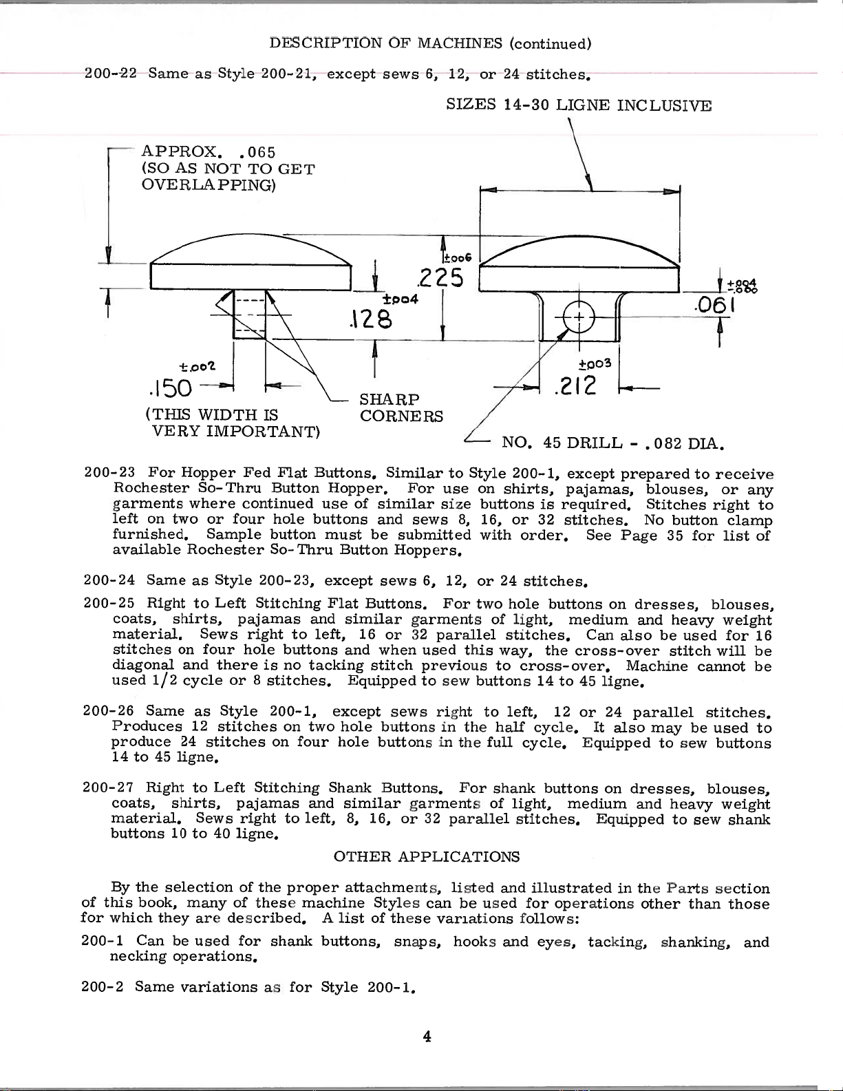
200-21
For
including
32
stitches.
within
Hopper
other
Rochester
Button
dimensions
Fed
Shank
Shank
Hopper
Buttons,
Button
indicated
handles
Similar
Hopper.
self
on
sketch
to
Stitches
molded
on
Style
next
200-6,
back
shank
page.
3
front
to
buttons
except
and
from
prepared
sews
14
for
and
8,
16,
or
to
30
higne
Page 4
DES
C
IUPTJON
OF
MACI
[INES
(continued)
200-22
200-23
left
Same
APP[LOX,
(SO
OVERLAPPING)
•I5O
(THIS
VERY
For
Rochester
garments
on
furnished.
available
as
AS
NOT
WIDTH
IMPORTANT)
Hopper
So-Thru
where
two
or
Sample
Rochester
Style
four
200-21,
.065
TO
GET
IS
Flat
Fed
Button
continued
hole
button
So-Thru
except
SHARP
Buttons.
Hopper.
use
buttons
must
Button
sews
±po4
CORNERS
Similar
of
similar
and
be
submitted
Hoppers.
225
For
sews
6,
12,
SIZES
to
use
size
8,
or
1
Style
on
buttons
16,
with
24
14-30
NO.
200-1,
shirts,
or
stitches.
45
is
32
order.
LIGNE
212
DRILL
except
pajamas,
required.
stitches.
•
See
INCLUSIVE
-
.082
prepared
blouses,
Stitches
No
button
Page
35
•05(
DIA.
to
right
for
receive
or
clamp
list
any
to
of
200-24
200-25
200-26
200-27
of
this
for
200-1
Same
Right
coats,
material.
stitches
diagonal
used
Same
Produces
produce
14
to
Right
coats,
material.
buttons
By
the
book,
which
Can
necking
shirts,
on
1/2
24
45
ligne.
shirts,
10
selection
they
be
operations.
Style
as
Left
to
Sews
four
and
there
cycle
as
Style
12
stitches
stitches
to
Left
Sews
to
40
many
are
used for
200-23,
Stitching
pajamas
right
hole
or8stitches.
pajamas
right
buttons
no
is
200-1,
on
on
Stitching
to
to
L[gnc.
of
the
proper
of
these
described.
shank
except
Flat
and
left,
tacking
two
four
Shank
and
left,
machine
A
buttons,
Buttons.
similar
16
and
stitch
Equipped
except
hole
hole
similar
8,
16,
OTHER
attachments,
Styles
list
of
sews
when
buttons
buttons
Buttons.
6,
garments
:J2
or
sews
these
snaps,
parallel
used
previous
to
right
in
in
garments
::2
or
APPLICATIONS
can
variations
12,
For
this
sew
the
the
For
parallel
listed
be
hooks
24
or
two
of
way,
to
buttons
to
half
full
shank
of
and
used
and
stitches.
hole
buttons
light,
stitches.
the
cross-over.
14
to
left,
light,
12
cycle.
cycle.
buttons
stitches.
illustrated
for operations
follows:
eyes,
medium
Can
cross-over
45
ligne.
or
It
Equipped
medium
Equipped
tacking,
on
24
also
on
in
dresses,
and
also
Machine
parallel
may
dresses,
and
the
other
heavy
be
used
stitch
cannot
be
to
sew
heavy
to
sew
Parts
than
shanking,
blouses,
weight
for
will
stitches.
used
buttons
blouses,
weight
shank
section
those
16
be
be
to
and
200-2
Same
variations
as
for
Style
200-1.
4
Page 5
200—6
(biii
and
be
ice
used
ipopo
k
for
oil!
shank
rat
CRACP
buttons,
ions
I
;inc]
niwd)
t
shank—
eyes,
drapery
rings,
laRki
ug,
(Con
()NS
[CA
I.
hooks
200—]
200—8
200—P
200—10
200—
and
200—16
rings.
200—17
starts.
seconds
tile
Page
Same
Can
Same
Can
IuCan
neck
(bun
Same
These
at
Most
fact
14,
ing
machines
Use
1000
of
they
will
var
used
he
var
used
be
used
be
opera
used
he
variations
a
good
tile
are
be
ions
Lt
Co
oils
i
i
at
for
for
1
t
for
should
grade
Fahrenheit.
oiling
painted
beneficial.
as
snaps
r
as
shanking
shank
Oils
two
as
places
for
for
for
be
of
red.
,
buttons,
ho
straight
Style
drapery
Style
operations
buttons,
e
1
Style
oiled
on
However,
OILING
the
200—6.
rings
200—8.
snaps
200—16.
twice
mineral
machines
,
,
sti
telied
daily,
reference
Lacking
hooks
before
oil
are
and
back
of
readily
to
,
a
the
and
eves
to
tile
Saybolt
sluanking
,
tacking,
front
morning
identifiable
oiling
only,
viscosity
diagram
ope
and
ions
rat
shanking
and
drapery
afternoon
of
because
Fig.
90
13,
,
and
125
to
of
on
open
places.
of
grease
pulley
greasing
are
short
should
of
the
a
stay
Please
the
Also
should
oiled.
Tubes
The
Needles
shank,
Generally
be
button,
button
note
hinged
note
is
base
that
furnished
be
place
is
grease
of
recommended
for
and
speaking,
used.
thickness
is
that
covers
there
removed,
indicated
may
speed
these
long
making
In
be
to
it
will
with
be
machines
with
the
of
used.
and
is
the
the
by
ordered
of
extra
the
material,
be
tilt
label
a
machine,
grease
the
these
are
shortest
selection,
necessary
machine
on
level
letter
under
SPEED
machines
NEEDLES
divided
short
the
and
shank.
needle
amount
to
remove
on
its
pulley
periodically,
checked
‘TAfl
part
is
into
in
the
No.
1500
three
required
consideration
of
shanking
arm
side
which
and
diagram.
28604
R.P.M.
cover
to reach
reads
replenished
P.
categories
to
perform
should
required,
the
and s-ide
some
HGrease
plug
screw
if
other
All
—
short,
a
given
be
given
and
cover,
of
the
Her&’.
in
recuuired.
places
long
operation
to
the
whether
oiling
the
and
tube
A
shown
with
height
or
to
Tile
not
5
Page 6
the
height
long
the
extra
be
set
catalog.
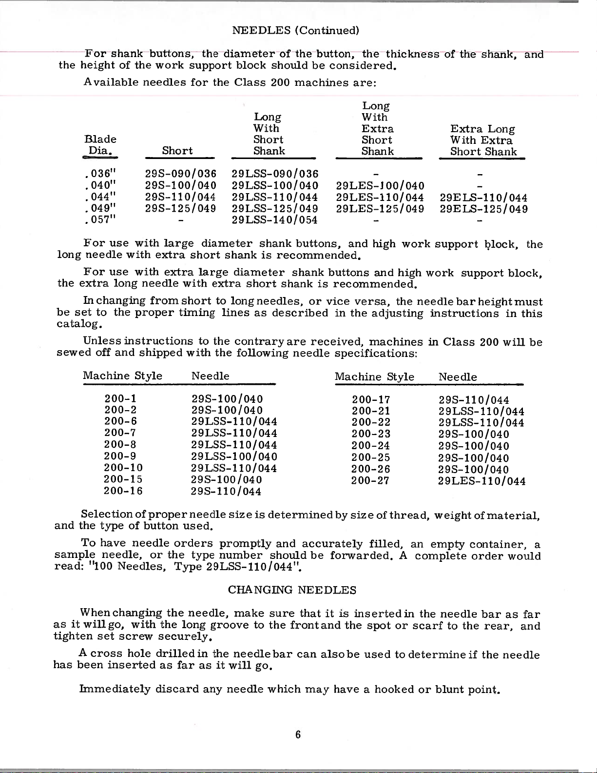
For
shank
Available
Blade
Dia.
•
036”
•
040”
•
044”
•
049”
•
057”
For
use
needle
For
use
long
In
changing
to
the
of
the
needles
29S—090/036
29S—100/040
29S—1l0/044
29S—125/049
with
with
with
needle
proper
buttons,
work
Short
large
extra
extra
from
support
for
short
with
short
timing
the
the
diameter
large
extra
to
lines
NEEDLES
diameter
block
Class
29LSS-090/036
29LSS-100/040
29LSS-ll0/044
29LSS—125/049
29LSS-140/054
shank
diameter
short
long
of
should
200
Long
With
Short
Shank
shank
recommended.
is
needles,
described
as
(Continued)
the
machines
buttons,
shank
shank
button,
considered.
be
29LES-J
29LES—110/044
29LES—125/049
buttons
is
recommended.
or
vice
in
are:
and
versa,
the
the
Long
With
Extra
Short
Shank
high
and
adjusting
thickness
00/040
work
high
the
needle
the
of
Extra
With
Short
29ELS-l10/044
29ELS—125/049
support
work
instructions
support
bar
shank,
Long
Extra
Shank
block,
height
block,
must
in
this
and
the
sewed
and
sample
read:
it
as
tighten
has
Unless
off
Machine
200—15
200—16
Selection
the
type
To
have
needle,
“100
When
wiligo,
set
A
cross
been
instructions
and
200—1
200—2
200—6
200—7
200—8
200—9
200—10
of
Needles,
changing
with
screw
hole
inserted
shipped
Style
proper
of
button
needle
or
used.
orders
the
Type
the
the
long
securely.
drilled
as
far
to
the
contrary
with
the
following
Needle
29S—
100
040
/
29S—100/040
29LSS-110/044
29LSS—110/044
29LSS—110/044
29LSS—100/040
29LSS—110/044
29S—100/040
29S—110/044
needle
type
needle,
in
as
size
promptly
number
29LSS-110/044”.
CHANGING
make
groove
the
needle
it
will
is
determined
and
should
sure
to
the
bar
go.
are
received,
needle
accurately
be
NEEDLES
that
front
can
specifications:
Machine
200—17
200—21
200-22
200—23
200-24
200—25
200—26
200—27
size
by
forwarded.
it
is
inserted
and
the
also
be
machines
Style
thread,
of
filled,
spot
used
an
A
in
or
scarf
to
determine
in
Class
Needle
29S—
29LSS—110/044
29LSS—110/044
29S—100/040
29S—100/040
29S—100/040
29S-100/040
29LES—110/044
weight
empty
complete
the
needle
to
200
110/044
of
container,
order
bar
the
rear,
if
the
will
material,
would
as
needle
be
a
far
and
Immediately
discard
any
needle
which
6
may
have
hooked
a
or
blunt
point.
Page 7
lip.
‘Jo
13,
Lb
iad
Page
iuaeli
Ui.
‘l’i
I
RIAI).[NC1
ii
IC,
)UI.
ill
S
IOJ)
position,
ADJUSTING
and
thread
ill
accordance
with
cliagrani.
opu
‘I
‘
b
I
operated,
operating
With
set
so
plunger
obtain
to
there
the
pulley
set
CAUTION
i’ations
ALb
depress
direction.
the
that
lever
this
is
1/32
is
screw
UntIl
—
machine
there
bracket
setting.
inch
pressed
(L)
Do
L’eady
ZB
A—
I
ig.
the
is
clearance
is
nut
run
to
H
1
operating
in
stop
3/8
(B).
Lock
intowards
securely
the
sew.
ADJUSTING
position,
inch
Loosenthe
the
between
tightened.
machine
-.P’
treadle,
clearance
back
machine.
nut.
ball
the
back
Lindel’
with
one
produce
and
ence
position’’
in
pawl
position
and
CLUTCH
stop
between
lock
Adjust
(G)
Lock
power
The
a
pressure
automatically
In
the
is
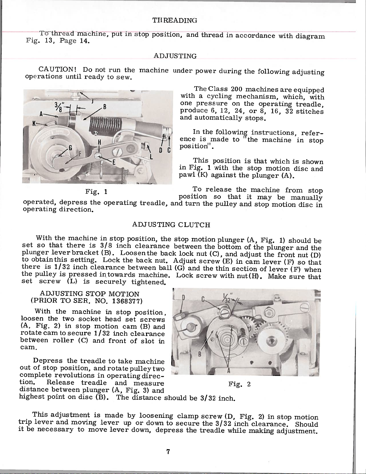
This
Fig.
(K)
To
turn
motion
nut
screw
and
screw
Class
cycling
6,
made
1
against
release
the
the
(C),
the
during
12,
followinç
position
with
so
pulley
plunger
bottom
and
(E)
thin
with
the
200
mechanism,
on
the
24,
to
‘
is
the
the
the
that
and
of
adjust
in
section
nut(H).
following
machines
operating
or
8,
stops.
instructions,
the
machine
that
stop
plunger
machine
it
may
stop
(A,
Fig.
the
cam
lever
of
16,
which
motion
motion
plunger
the
lever
Make
are
which,
(A).
be
1)
front
(F)
adjusting
equipped
treadle,
32
stitches
in
is
disc
from
manually
disc
should
and
nut
so
(F)
sure
with
refer
stop
shown
and
stop
in
be
the
(D)
that
when
that
(PRIOR
With
loosen
(A,
rotate
between
cam.
Depress
out
of
complete
tion.
distance
highest
This
trip
lever
it
be
ADJUSTING
TOSER.
the
the
Fig.
2)
cam
roller
stop
revolutions
Release
between
point
adjustment
and
necessary
to
position,
two
in
secure
the
on
STOP
machine
socket
stop
(C)
treadle
treadle
plunger
disc
moving
to
NO.
motion
1
and
and
in
(B).
is
move
MOTION
in
head
32
/
front
to
rotate
operating
made
lever
lever
1368377)
stop
set
cam
inch
clearance
of
take
pulley
and
Fig.
(A,
The
by
up
position,
screws
(B)
slot
machine
direc
measure
3)
distance
loosening
or
down
down,
and
in
two
and
depress
should
to
secure
7
p
clamp
the
be
C
3/32
screw
the
treadle
inch.
3/32
Fig.
(D,
while
,(
Fig.
inch
—.
2
2)
clearance.
making
NI
in
stop
adjustment.
motion
Should
Page 8
Iffective
Assembly
With
2A)
lig.
elongated
“right
front
the
NOTE:
Depress
complete
between
1/4
be
stop
Should
adiustment.
motion
the
and
cam”
of
1.
revolutions
plunger
inch.
become
it
with
has
machine
screw
slot
(I))
slot
This
associated
the
Adjustment
trip
Retighten
been
(as
as
in
dimension
treadle
(A,
necessary
AI)J
Serial
incorporated,
in
(13).
viewed
required
cam
adjustments.
in
operating
Fig.
lever
clamp
No.
stop
(D);
to
3A)
can
and
USTIN(
position,
Rotate
Fig.
in
to
tighten
MUST
take
and
be
moving
move
to
screw
STOP
1368377,
for
“left
2A)
obtain
set
remain
machine
direction.
the
made
the
which
cam”
1/32
highest
by
lever
lever
(F).
I\IOTI(
an
loosen
and
screws
constant:
out
Release
loosening
up
)N
‘improved’’
following
the
the
counterclockwise
(C)
tighten
stop
point
or
clearance
(A).
down
depress
inch
of
down,
(Conlin
two
screw
regardless
position,
treadle
disc
on
clamp
to
ued)
Stop
instructions
socket
screw
attain
Motion
(B).
between
and
(13).
the
head
Rotate
of
then
measure
The
(F,
sp3cified
treadle
Cam
set
to
other
rotate
distance
Fig.
apply:
screws.
the
cam
roller
the
while
(e:
and
of
top
(C)
(1)
related
pulley
distance
should
2A)
in
clearance.
making
r
(A
its
and
and
or
two
the
Step
Step
Step
NOTE:
SOFT
1.
2.
3.
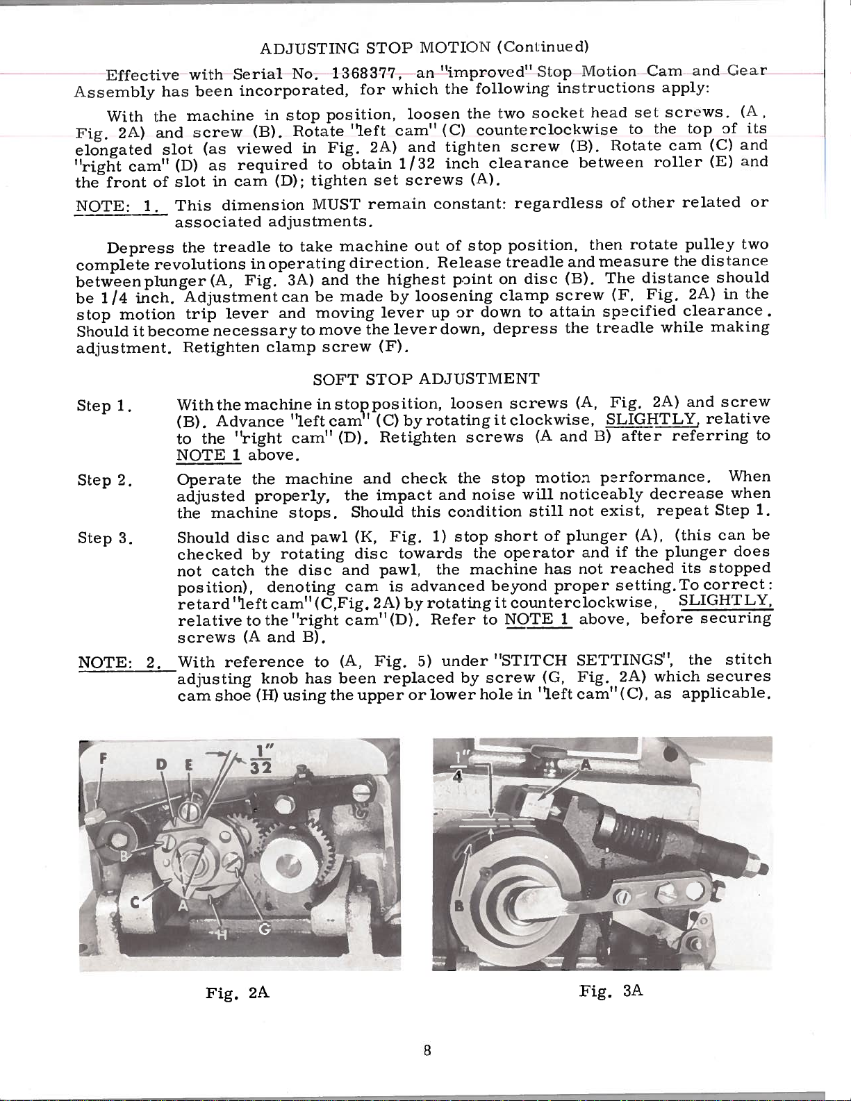
Withthemachineinsto?position,
Advance
(B).
“right
the
to
above.
1
machine
disc
catch
“left
to
(A
reference
shoe
the
properly,
and
rotating
by
the
denoting
cam”(C,Fig.
the”right
and
knob
using
(H)
I,
2.
NOTE
Operate
adjusted
the
Should
checked
not
position),
retard
relative
screws
With
adjusting
cam
“left
cam”
machine
stops.
pawl
disc
B).
to
has
STOP
carn’(C)
(D).
and
the
Should
(K,
disc
and pawl,
cam
cam”(D).
(A,
been
upper
the
impact
2A)
Fig.
ADJUSTMENT
by
Retighten
check
this
Fig.
towards
is
advanced
by
5)
replaced
or
loosen
rotating
the
and
condition
stop
1)
the
rotating
Refer
under
lower
screws
noise
the
machine
to
screw
by
hole
screws
it
clockwise,
(A
and
stop
beyond
motion
will
noticeably
still
short
it
“STITCH
of
operator
has
proper
counterclockwise,
NOTE
in
1
(G,
“eft
(A,
Fig.
SLIGHTLY,
after
13)
parformance.
exist,
not
plunger
if the
and
reached
not
setting.To
above,
SETTINGS”,
2A)
Fig.
cam”(C),
2A)
decrease
repeat
(A),
before
which
as
and
relative
referring
(this
plunger
its
stopped
correct:
SLIGHTLY,
securing
the
secures
applicable.
screw
When
when
Step
can
stitch
to
1.
be
does
cJ7jzñ
Fig.
2A
8
Fig.
3A
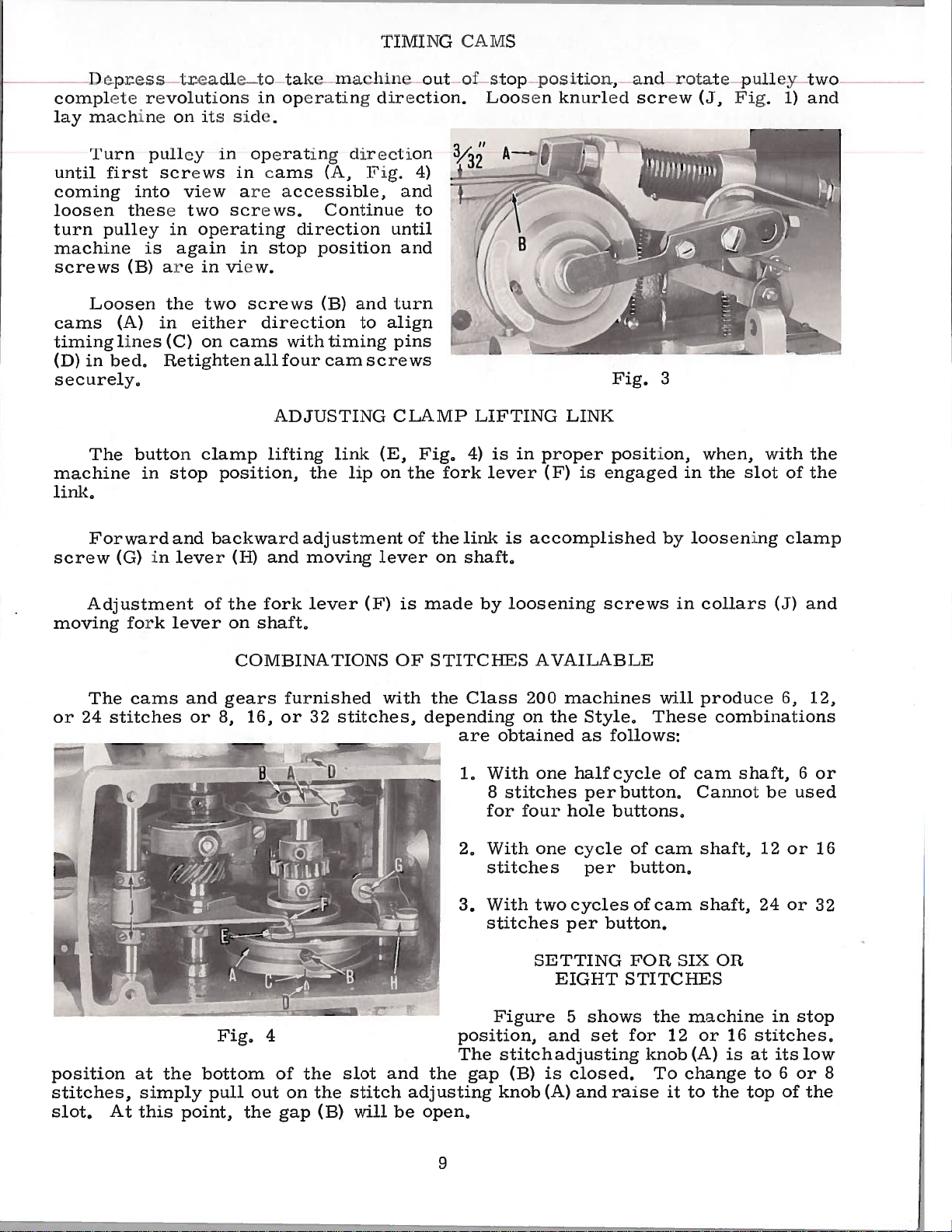
Page 9
—
complete
n:i.eiunc
Liy
.[urti
unLL[
coming
loosen
turn
machine
screws
Loosen
cams
timing
iii
(D)
securely,
rfhe
machine
link,
p
iirst
these
pulley
(B)
(A)
lines
bed,
I.
revolutions
on
pulLey
screws
].nLO
View
in
again
is
arc
the
in
(C)
Itetighten
button
in
stop
it
two
ope
at
its
in
two
I.e
5
iii
in
arc
Sc
rati.i
view.
to
III
(ic
o)e1:aLiIig
LcceSSItilc,
ec
w5,
ig
in
stop
screws
Lake
01
in-
either direction
on
cams
all
whh
four
ADJUSTING
clamp
lilting
position,
)C
I
eec
position
the
(
i
iaeii
atLng
(lirertiodi
iig.
(A,
Conlinue
on
Li
and
U)
to
timing
cam
sc
link
lip
‘r[IVIiNG
on
inc
(I
LecuLon.
4)
and
1:0
until
and
turn
align
pins
CWS
CLAMP
iig.
(E,
on
the
L
fork
CAMS
ol
to1)
S
oosen
LIFTING
is
4)
lever
in
pos
knurled
proper
(F)
it
LINK
is
ii,
and
Screw
Fig.
position,
engaged
3
rotate
(J,
in
when,
the
pn
Fig.
slot
[Icy
with
1)
of
two
and
the
the
Forward
screw
Adjustment
moving
The
or
24
(G)
fork
cams
stitches
in
and
lever
lever
and
or
backward
(Ii)
and
the
on
fork
shaft,
of
COMBINATIONS
gears
8,
16,
furnished
or
w
H
ad,j
ustment
moving
lever
32
0
(F)
stitches,
of
lever
is
made
OF
STITCHES AVAILABLE
with the
depending
the
on
link
is
accomplished
shaft,
loosening
by
Class
are
1,
2,
obtained
With
8
stitches
for
With
200
on
four
stitches per
3.
With
stitches per
SETTING
screws
machines
Style,
the
as
follows:
one
half
cycle
per
button,
buttons,
hole
one
cycle
of
button,
two
cycles
of
button.
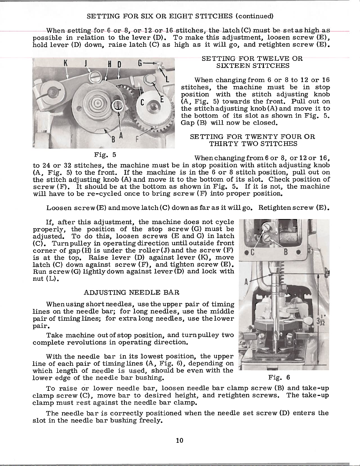
FOR
EIGHT STITCHES
by
in
will
loosening
collars
produce
clamp
(J)
6,
These combinations
cam
Cannot
shaft,
shaft,
OR
shaft,
12
24
be
or
or
of
cam
cam
SIX
and
12,
6
used
or
16
32
Figure
position
stitches,
slot,
At
at the
simply
this
bottom
point,
Fig,
pull
out
the
the
open,
position,
The
stitch
gap
knob
4
the
slot
stitch
will
arid
adjusting
be
of
gap
on
the
(B)
(B)
and
adjusting
is
(A)
9
shows
5
set
closed.
and
for
raise
the
knob
To
12
it
change
to
machine
or
16
(A)
is
the
in
stitches,
at
its
6
to
top
of
stop
low
or
the
8
Page 10
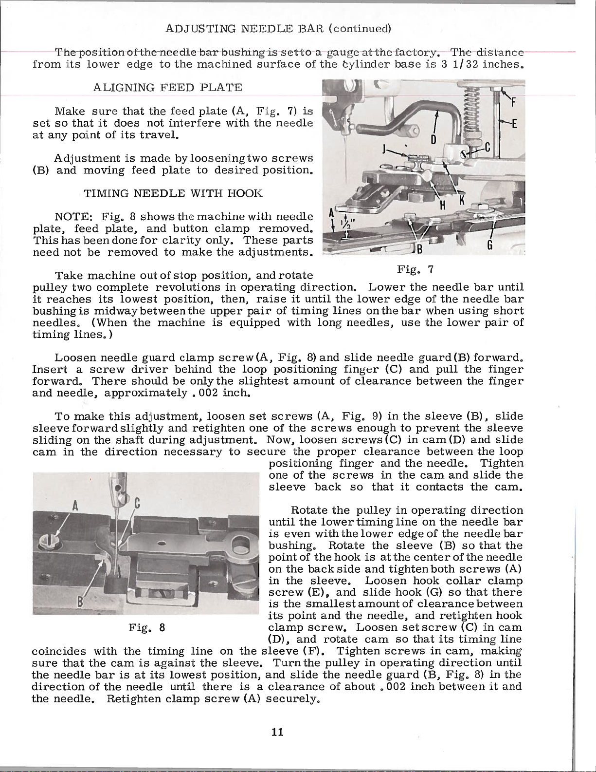
SETTING
FOR
SIX
OR
EIGHT
STITCHES
(continued)
When
possible
hold
24
to
(A,
Fig.
stitch
the
screw
will
in
lever
or
32
5)
(F).
have to
setting
relation
down,
(D)
stitches,
to
the
adjusting
should
It
be
for
Fio’.5
front.
knob
re-cycled
6
to
raise
HO
the
be
or
the
machine
(A)
at
3,
or
lever
latch
F
If
the
and move
the
once
or
12
(D).
(C)
must
machine
bottom
to
bring
as
16
be
it
as
stitches,
make
To
high
stitches,
position
(A,
the
the
Gap
in
is
to
the
shown
screw
the
latch(C)
this
adjustment,
will
SIXTEEN
changing
the
with
towards
5)
adjusting
of
now
FOR
6
or
of
Fig.
proper
go,
machine
the
its
8
stitch
its
5.
as
it
SETTING
When
Fig.
stitch
bottom
will
(B)
SETTING
THIRTY
Whenchangingfrom6or
position
stop
in
the
bottom
in
into
(F)
must
and
FOR
STITCHES
from
stitch
the
knob
slot
closed,
be
TWENTY
TWO
with
slot.
it
If
position.
be
loosen
retighten
TWELVE
6
or8to
must
adjusting
front.
(A)
as
shown
STITCHES
stitch
position,
Check
is
not,
set
as
screw
screw
OR
be
Pull
and
move
in
FOUR
8,
or
adjusting
pull
position
the
high
12
or
in
stop
knob
out
it
Fig.
OR
12
or
knob
out
machine
as
(E),
(E).
16
on
to
5.
16,
on
of
Loosen
If,
properly,
adjusted.
(C).
corner
is
latch
Run
nut
lines
pair
pair.
complete
line
which
lower
clamp
clamp
Turn
at
the
(C)
screw(G)
(L).
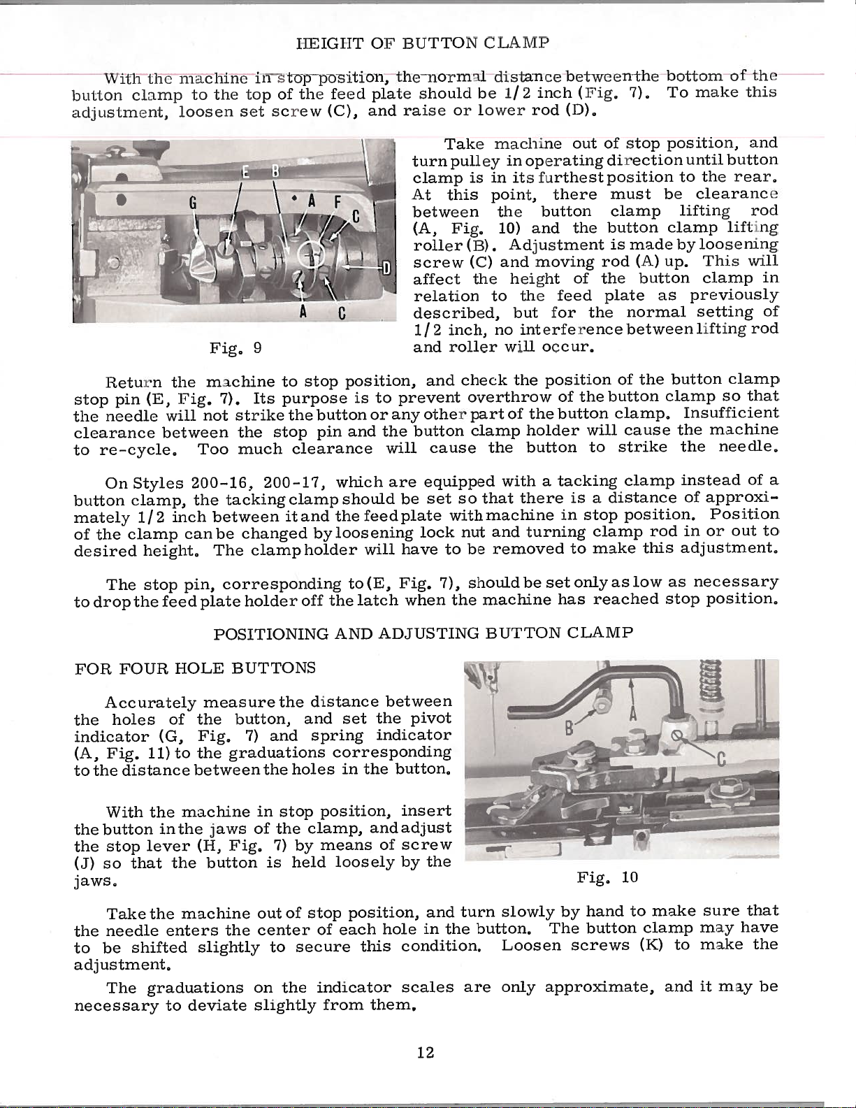
Whenusingshortneedles,
on
of
Take
With
of
length
edge
To
screw
must
after
the
To
pulley
of
gap
top.
down
the
timing
machine
revolutions
the
each
raise
screw(E)
of
adjustment,
this
position
do
this,
in
is
(H)
Raise
against
lightly
ADJUSTING
needle
lines;
outofstop
needle
of
the
or
(C),
of
needle
needle
lower
move
against
pair
rest
andmovelatch(C)
of
the
loosen
operating
lever
screw
in
needle
bar
the
against
NEEDLE
for
extra
operating
its
in
lines
is
used,
bar
the
under
down
bar;
for
bar
timing
the
stop
screws
direction
roller
against
(D)
(F),
use
long
long
position,
lowest
(A,
bushing.
bar,
to
desired
needle
machine
(J)
and
lever(D)
BAR
the
upper
needles,
needles,
direction.
position,
Fig.
should
loosen
bar
downas
screw
(E
until
and
lever
tighten
and
6),
be
height,
clamp.
faras
does
and
use
turnpulley
not
(G)
G)
outside
the
screw
(K),
screw
lock
and
pair
the
use
the
the
depending
even
needle
must
in
of
with
and
it
cycle
latch
front
move
(E).
with
timing
middle
lower
two
upper
the
bar
retightcn
willgo.
be
(F)
on
clamp
Retightenscrew
.0
—
/
r
screw
screws.
(E).
B
L
6
and
The
—
‘H
take-up
take-up
rr
T’
Fig.
(B)
slot
The
in
needle
the
needle
bar
bar
is
correctly
bushing
positioned
freely,
when
10
the needle
set
screw
(D)
enters
the
Page 11
AI)I
IISTIN(1
NIII)IJ
HAH,
(lLiiuu(I)
rrta
-
rII1
Icom
iViakesnrc
so
set
at
any
Adj
and
(B)
NOTE:
plate,
This
neec[
Take
pulley
reaches
it
bushing
needles,
timing
LLS
has
not
position
iowei’
that
ponL
ustm
moving
TIM
feed
been
be
machine
two
is
lines,)
A
I
d(;
it
ilocs
of
cut
[NG
Vig,
plate,
done
removed
complete
its
midway
(When
ol.
edge
N1NG
that
its
is
feed
NEED
3
lowest
the
the
needle
to
i’iII)
the
not
tn:avel,
made
pLate
shows
and
clarity
for
to
out
of
revolutions
position,
between
machine
Line
Iced
mt,erlere
l.oos
by
Wirf.[I
Ii
the
button
make
stop
the
ha
hush
lliaeIniliu(l
PT
plate
with
cuing
desired
to
machine
clamp
only,
the
position,
in
then,
upper
is
iing
surl’aue
(A,
i
the
two
JQQ
with
removed,
These
adjustments,
and
operating
raise
pair
equipped
is
setto
1g.
7)
ineedte
sc
cc
position,
needle
parts
rotate
of
with
of
is
ws
direction,
until
it
timing
a
the
long
cylinder
the
lines
needles,
I.
Lower
lower
on
Line
the
au
hase
i.
edge
bar
use
tory,
the
is
7
needle
01
when
the
3
the
lower
Tine
1/32
using
distatien
bar
needle
innulics,
I
until
bar
short
pair
of
Loosen
Insert
forward,
and
needle,
To
sleeve
sliding
cam
coincides
sure
the
needle
direction
the
needle,
a
make
forward
on
in the
that
needle
screw
There
approximately
this
slightly
the
shaft
direction
cam
bar
the
Retighten
the
is
with
the
of
guard
driver
should
adjustment,
during
t1j
Fig.
timing
is
against
at
its
needle
clamp
behind
be
and
necessary
8
lowest
until
clamp
screw(A,
the
the
only
002
,
inch,
loosen
retighten
adjustment,
to
-—Z4
on
line
the
sleeve,
position,
there
screw
loop
slightest
set
one
secure
the
sleeve
is
a
(A)
Fig.
positioning
amount
screws
of
the
Now,
loosen
the
positioning
one
of
sleeve
Rotate
until
is
the
even
bushing,
point
on
of
the
in the
screw
is
the
its
point
clamp
and
(D),
Turn
and
slide
clearance
securely,
and
8)
(A,
screws
proper
the
back
lower
with
the
backside
sleeve.
(E)
9
smallest
and
screw.
rotate
(F),
pulley
the
the
slide
finger
of
clearance
Fig,
enough to
screws
clearance
finger
screws
so
the pulley
timing
the
lower
Rotate
hook
is
and
Loosen
and
slide
amount
the
Loosen
cam
Tighten
in
needle
of
about,002
needle
(C)
in
9)
(C)
and
in
that
the
at
needle,
screws
operating
guard
guard
and
between
the
sleeve
prevent
in
cam(D)
between
the
needle,
the
cam
it
contacts
in
operating
line
on
of
edge
sleeve
the
center
tightenboth
hook
hook
of
(G)
clearance
and
setscrew
so
that
(B,
inch between
pull
and
the
the
(B)
collar
so
ret
its
in
cam,
direction
Fig,
(B)
the
the
(B),
the
needle
needle
so
of
the
screws
that
ighten
(C)
timing
forward,
finger
finger
slide
sleeve
and
slide
the
Tighten
slide
the
cam.
direction
that
needle
clamp
there
between
hook
in
making
until
in
8)
it
loop
the
bar
bar
the
(A)
cam
line
the
arid
11
Page 12
buLi
a(Ijus
\V
id
Lnicnt,
ith
or
CL\\IP
distance
be
lower
1/
2
inch
rod
between
(i’ig,
(D),
7),
the
bottom
make
To
of’
t.Iit
this
OV
plate
and
13LTTON
normal
the
should
raise
iiIICil’I’
position,
stop
m
p
loosen
ulilno
lu
Liii’
c
in
the
set
in
Lop
of
screw
the
teed
(C),
L
[tetu:i’n
pi.n
stop
the
neec[lc
clearance
re-cycle,
to
On
button
mately
the
of
desired
(E,
Styles
clamp,
1/2
clamp
height,
6
the
Vig.
will
between
Too
200—16.
the
inch
canbe
Fig,
ichine
m
7).
not
tacking
between
The
9
to
purpose
Its
strike
the
stop
much
200-17,
changed
clampholder
A
A
stop
button
the
pin
clearance
clamp
it
and
byloosening
C
position,
is
and
which
should
feeciplate
the
will
to
or
prevent
any
the
will
are
turn
clamp
At
between
(A,
roller
screw
affect
relation
described,
2
1/
and
and
other
button
cause
equipped
set
be
lock
have
Take
pulley
this
Pig,
(13),
inch,
roller
check
overthrow
so
with
nut
to
be
in
is
point,
(C)
the
to
part
clamp
the
that
machine
and
i.nachLne
in
operating
furthest
its
the
and
10)
Adjustment
and
moving
height
the
but
interference
no
will
the
the
of
holder
button
with
there
turning
removed
out
there
button
the
feed
for
occur,
position
of
button
tacking
a
is
in
to
of
the
the
will
to
a
stop
clamp
make
of
stop
direction
Ltion
pos
must
clamp
button
macic
is
(A)
rod
the
plate
normal
between
of
button
clamp,
cause
strike
clamp
distance
position,
be
up.
button
as
the
clamp
rod
this
position,
until
to
the
clearance
lifting
clamp
loosening
by
This
clamp
previously
setting
lifting
button
Insufficient
machine
the
the
instead
approxi
of
Position
or
in
adjustment.
button
rcai’,
lifting
will
clamp
that
so
needle,
of
out
mid
rod
in
oF
rod
a
to
The
drop the
to
FOR
FOUR
Accurately
holes
the
indicator
(A,
Fig.
distance
the
to
With
button
the
stop
the
that
so
(J)
jaws.
Take
needle
the
be
shifted
to
adjustment,
The
necessary
pin,
stop
feed
HOLE
of
the
Fig,
(G,
the
to
11)
between
machine
the
inthe
lever
(I-I,
the
machine
the
enters
slightly
graduations
to
deviate
corresponding
plate
holder
POSITIONING
BUTTONS
measure
button,
7)
and
graduations
the
in
jaws
button
of
Fig,
is
out
center
the
to
on
slightly
the
stop
the
7)
holes
held
of
the
off
distance
and
spring
position,
clamp,
means
by
stop
of
secure
indicator
the
from
to(E,
latch
AND
Fig.
when
ADJUSTING
between
the
set
indicator
corresponding
button,
the
in
insert
adjust
and
screw
of
loosely
by
position,
this
hole
condition,
each
scales
them,
pivot
the
and
in
7),
the
the
shouldbe
machine
BUTTON
turn
button,
are
slowly
Loosen
only
onlyas
set
reached
has
CLAMP
Fig,
hand
by
button
The
screws
approximate,
10
low
to
(K)
stop
make
clamp
and
as
to
necessary
position,
sure
may
make
may
it
that
have
the
be
12
Page 13
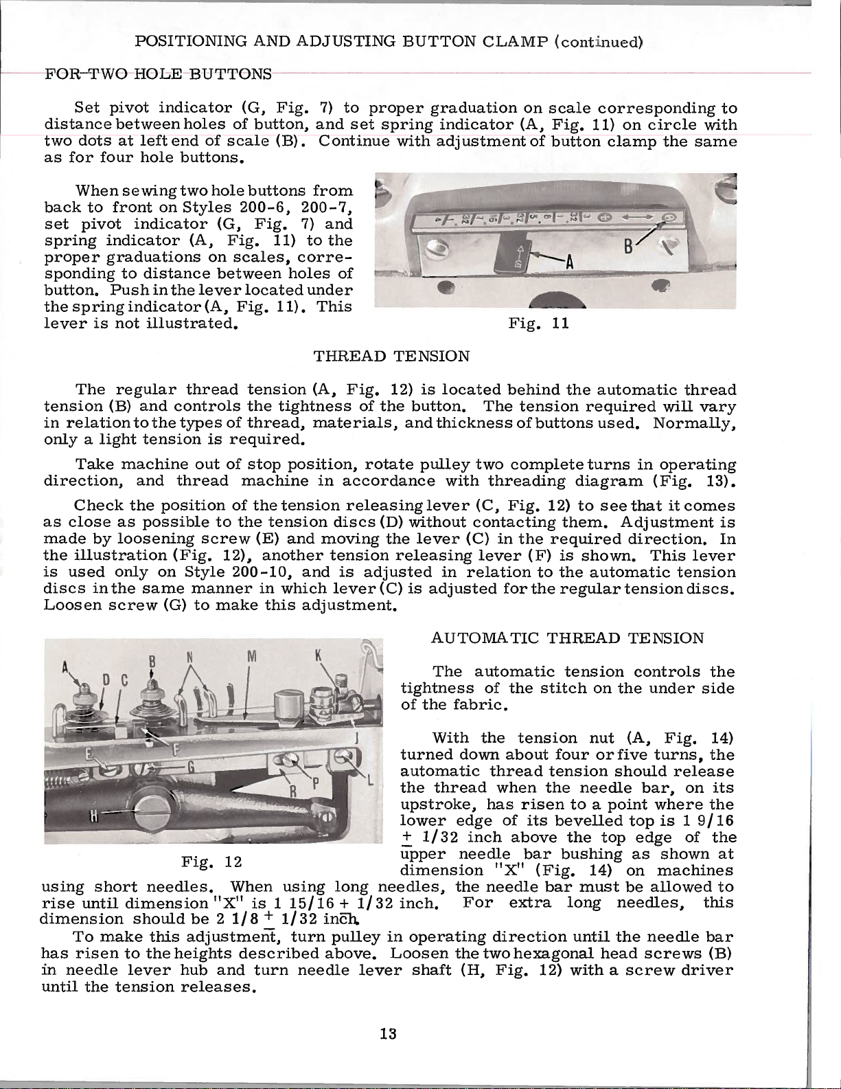
POSITIONING
AND
LAM
A
HUTTON
C
P
(continued)
FOR
Set
clista!lce
two
clots
br
as
When
back
pivot
set
spring
proper
sponcling
button,
the
spring
lever
The
tension
in
relation
only
a
Take
direction,
Check the
as
close
made
the
illustration
is
used
discs
Loosen
TWO
pvoL
between
at
Four’
sewing
to
front
indicator
graduations
to
Push
is
not
regular
(B)
light
machine
as
loosening
by
only
inthe
screw
hOLE
Lndicator
leFt
hole
on
indicator
distance
in
indicator
illustrated.
and
to
the
tension
and
position
possible
on
same
(G)
BUTTONS
holes
end
buttons.
two
Styles
(A,
the
thread
controls
types
thread
(Fig.
Style 200-10,
manner
of
on
lever
(A,
is
out
screw
to
of
scale
hole
(G,
Fig.
scales,
between
Fig.
of
required.
of
of
to
12),
make
(G,
button,
buttons
200-6,
Fig.
located
tension
the
thread,
stop
machine
the
the
tension
(E)
another
in
this
I’ig.
.
(B)
200—7,
7)
to
11)
corre
holes
under
11).
tightness
position,
tension
and
and
which
adjustment.
to
7)
and
set
Continue
from
and
the
of
This
THREAD
Fig.
(A,
materials,
in
accordance
releasinglever
discs
moving
tension
is
lever(C)
peoper graduation
sprlng
I
12)
of
the
rotate
(D)
the
adjusted
with
TENSION
releasing
adjustment
•f
is
button.
and
thickness
pulley
without
lever
is
adjusted
indicator
located
with
in
Fig.
behind
The
complete
two
threading
Fig,
(C,
contacting
in
(C)
lever
relation
for
on
(A,
of
tension
of
buttons
the
(F)
to
the
scale
Iig,
button
11
12)
required
corresponding
on
11)
(-
the
automatic
required
used.
turns
diagram
to
see
them. Adjustment
is
shown.
the
automatic
regular
circle
clamp
—
in
that
direction,
This
tension
the
same
I.
thread
will
vary
Normally,
operating
(Fig.
it
comes
lever
tension
discs.
to
with
13).
is
In
1
1I
using
rise
until
dimension
To
has
risen
in
needle
until
the
short
make
B
I
needles.
dimension
should
this
to
the
lever
tension
N
Fi
g.
be
2
adjustment,
heights
and
hub
releases,
M
‘
2
12
When
XI
1/8
described
is
+
turn
mE
R
using
1
15/16
1/32
turn
needle
K
in1i,
pulley
above.
long
+
I
1/32
lever
tightness
of
automatic
the
upstroke,
lower
+
upper
dimension
needles,
inch.
operating
in
Loosen
shaft
13
AUTOMATIC THREAD
The
the
With
thread
1/32
automatic
fabric.
the
edge
inch
needle
the
For
the
(H,
the
of
thread
when
has
of
above
‘X’
T
needle
extra
direction
two
Fig.
stitch
tension
tension
the
risen
its
bevelled
bar
bushing
(Fig.
bar
hexagonal
12)
tension controls
to
the
long
until
with
on
nut
needle
a
top
14)
must
head
TENSION
the
(A,
should
point
top
edge
as
on
be
needles,
the
a
screw
under side
Fig.
release
bar,
where
is
shown
machines
allowed
needle
screws
on
1
9/16
of
driver
the
14)
its
the
the
at
to
this
bar
(B)
Page 14
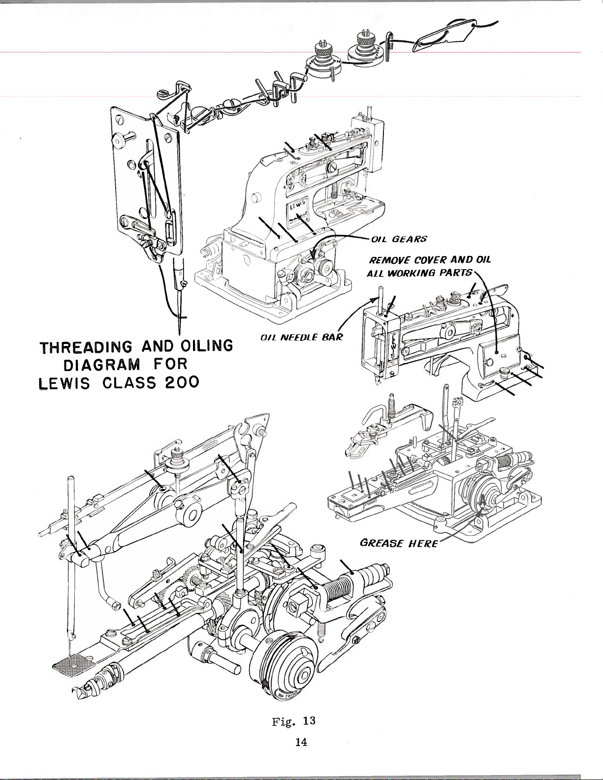
O1L
GEARS
REMOVE
WORKING
ALL
COVER
AND
PARTS
OIL
THREADING
DIAGRAM
LEWIS
CLASS
AND
FOR
200
OILING
OIL
NEEDLE
BAR
HERE
Fig.
13
14
Page 15
I
head
be
ru—checked,
11,
node
tension
101(1
screws
iiiter
ide
rs
nut
thu
iuud1.e
(K,
re—checking,
of.
(A,
tie
I
‘ig.
A
1i’I)\’IATlC
luvu
‘ig,
fabric,
11).
V
1.1).
shaft
it
the
This
is
situation
‘[‘H
in
is
[ound
this
READ
position
an
that
TES1O
extremely
excessively
can
be
while
important
helped
(continued)
retighitening
adjustment,
large
by
loops
applying
the
still
moore
two
hexagotia
and
exist
tension
sh1ohI)(I
on
the
at
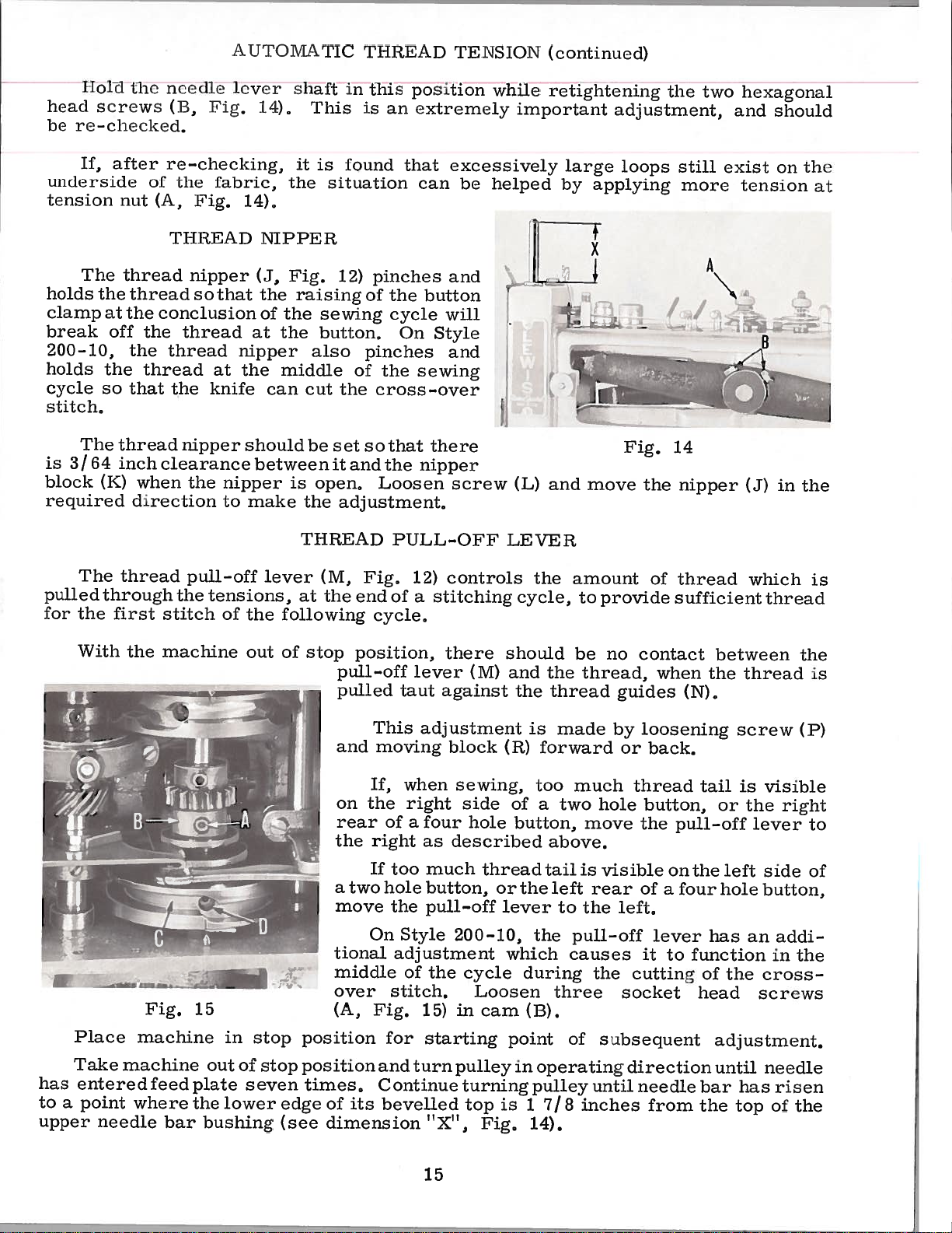
The
holds
clamp
break
200—10,
holds
The
is
3/
block
required
The
pulled
for
the
With
the
at
off
the
so
thread
64
mcli
(K)
through
first
thread
thread
the
the
the
thread
that
when
direction
thread
the
Tl[ItEAD
nipper
so
conclusion
thread
thread
at
the
knife
nipper
clearance
the
pull-off
the
tensions,
stitch
machine
that
nipper
the
nipper
to
of
N1PPE
(J,
the
of
at
can
should
between
make
lever
the
out
It
[ig.
raising
the
sewing
the
button,
also
middle
cut
be
is
open,
the
THREAD
(M,
at
the
following
of
stop
pinches
12)
of
pinches
of
the
the
cross—over
set
so
that
and
it
the
Loosen
adjustment.
Fig,
end
cycle,
position,
pull-off
pulled
and
the
button
On
will
Style
cycle
and
sewing
there
nipper
PULL-OFF
controls
12)
of
stitching
a
there
lever
taut
against
screw
(M)
-
(L)
LEVER
the
cycle,
should
and
the
the
and
amount
be
thread
1
move
to
provide
no
thread,
—
Fig.
the
contact
guides
14
of
thread
sufficient
when
nipper
(N),
between
thread
the
B
(J)
which
thread
in
1
the
is
the
is
,—
has
to
a
upper
Place
Take
entered
point
needle
Fig.
machine
machine
feed
where
bar
15
out
plate
the
bushing
in
of
seven
lower
stop
stop
edge
(see
and
on
rear
the
a
move
tional
middle
over
(A,
position
position
times,
of
dimension
two
its
This
moving
If,
the
of
right
If
too
hole
the
On
Style
adjustment
stitch.
Fig.
for
and
Continue
bevelled
adjustment
when
right
a
four
as
much
button,
pull-off
the
of
15)
starting
turn
“X”,
15
block
sewing,
side
hole
described
thread
or
200-10,
cycle
Loosen
in
cam
pulley
turning
top
Fig.
(R)
of
button,
the
lever
which
during
point
in
is
is
made
forward
too
two
a
above.
tail
left
to
the
three
(B).
operating
pulley
1
7/
14).
much
move
is
rear
the
pull-off
causes
the
of
until
inches
8
loosening
by
or
back.
thread
hole
button,
the
visible
of
left,
lever
it
cutting
socket
subsequent
direction
needle
from
pull-off
on
the
a
four
to
function
screw
is
tail
or
the
left
hole
has
of
the
head
adjustment.
until
has
bar
top
the
visible
lever
side
button,
an
cross
screws
needle
right
addi
in
risen
of
(P)
to
of
the
the
Page 16

the
Ti1
urn
p
roj
cam
ection
(K,
on
the
Vig,
nipper
III
ItHAD
15)
Ph
to
the
operating
IL—Oi’
right,
link,
V
as
and
LVVE
you
retighten
it
Lice
(continued)
it,
three
until
the
socket
lobe
head
stops
screws
aga
Lust
(A)
hi____
N
To
subsequent
complete
lay
and
cam
in
machine
until
right
to
securely,
Fig,
make
revolutions
machine
(C,
to
A
16
corrections
adjustment.
on
Fig,
is
speed
15)
again
its
comes
up
in
side,
in
knife
The
is
controlled,
to
the
If
loosen
easier
On
stitch
Take
operating
times,
the
to
should
knife
to
Take
operating
Turn
into
position,
stop
timing,
length
pull—oLE
much
too
screws
access
Style
the
at
machine
direction
Continue
top
snap
timing,
machine
direction,
pulley
view,
and
of
on
lever,
200—10,
middle
of
its
out
out
and
and
thread
Style
thread
(A,
link,
to
turning
stroke,
of
place
in
loosen
loosen
the
to
200—10,
tail
Fig,
TIMING
the
the
of
of
out
until
operating
machine
stop
of
Loosen
operating
this
left
tails
is
16)
remove
THE
knife
cycle.
stop
needle
pulley
At
position
screw.
screw(D),
to
on
the
by
visible
and
right
KNIFE
should
position
has
until
exactly
position,
in
knurled
direction
retard
an
raise
entered
stop
and
it,
front
additional
on
the
the
side
cut
and
needle
this
position
turn
base
until
Continue
Turn
Tighten
holes
right
link
cover,
cross-over
the
turn
feed
bar
point,
for
the
clamping
first
the
to
(A)
cam
buttons
of
adjustment
(B).
pulley
has
the
starting
slightly
hole,
eight
risen
knife
screw
screw
pulley
screws
front
plate
pulley
turn
all
Vor
in
two
The
effect
On
The
position
within
the
in
Changes
manner
To
Fig,
on
Style
1/16
cycle,
17),
slight
previous
200-15,
knife
when
inch
to
described
as
POSITIONING
position
and
amount
should
the
of
timing
move
timing
the
needle
the
knife,
bar
of
knife
snap
top
are
for
(B)
adjustment
the
of
should
out
bar
the
of
made
THE
in
200-10,
or
Style
loosen
cams
of
has
last
in
KNIFE
screws
out,
required
described
the
cut
operating
risen
up-stroke
same
the
16
thread
to
(A,
for
this
on
Page
at
setting
the
9
end
will
of
Fig,
have
the
17
no
stitching
noticeable
cycle,
Page 17

ILLUSTRATIONS
ORDERING
REPAIR
PARTS
various
of
actual
listing
a
required
position
ordering
cated
Example:
45
46
47
48
49
50
ed.
so
the
This
Numbers
The
catalog
position
of
in
of
parts.
Component
indenting
by
4124—49
It
will
reason
complete
sections
the
the
in
that
parts
18—968
18—730
18—925
666—19
137—19
be
has
been
of
the
the
first
their
that
machine.
with
in
use
sub—assemblies
of
in
replacement
in
parts
particular
the
part
Always
noted
is
sub—assembly
arranged
mechanism
their
view
column
illustration.
the
the
descriptions
Ball
Joint,
Spot
Set
Screw
Oil
Oil
above example
the
should
On
part
being
are
part
Screw
Wick
Wick
to
are
the
reference
number
lower,
Screw
of
be
simplify
shown
page
number,
shown.
which
under
Retainer
these
ordered.
so
opposite
description
numbers
Reference
listed
can
the
complete
that
parts
ordering
that
numbers
in
be
furnished
description
eccentric
the
individually
the
the
only,
the
repair
parts
illustration
and
and
second
of
parts.
may
the
merely
should never
column.
for
the
and
is
be
number
repairs
main
strap
not
Exploded
will
recommended,
views
seen
are
in
their
be
found
pieces
of
indicate
be
used
indi
are
sub—assembly.
not
list
the
in
1
1
1
2
1
1
in
this
only
numbers
SPECIAL
and
authorized
tific
bility
warded
directed.
At
the
book.
part
the
Where
represent
Success
Repair
principles,
are
Prices
f.o.b.
back
number
the
in the
assured.
are
shipping
A
charge
of
the
This
will
is
construction
the
operation
Parts
distributors.
net
as
and
cash
is
book
known.
same
furnished
are
and
point.
made
will
facilitate
permits,
part,
USE
made
subject
to
be
found
locating
IDENTIFYING
each
regardless
GENUINE
of
these
the
by
They
are
with
Parcel
cover
utmost
TERMS
to
Post
postage
a
PARTS
part
REPAIR
machines
Union
designed
precision.
change
shipments
numerical
the
is
of
catalog
PARTS
can
Special
according
without
and
illustration
stamped
be
are
insurance.
index
in
secured
Corporation,
Maximum
notice.
with
which
to
insured
of
the
all
description
and
its
they
only
most
efficiency
All
unless
the
parts
part
number.
appear.
with
its
subsidiaries
approved
shipments
otherwise
genuine
and
shown
when
scien
dura—
are
Part
UNION
for
17
Page 18

I,’
/7
-
p4
I
Page 19

BASE,
COVERS,
BUSHINGS
Ref.
No.
4
7
8
10
11
12
13
14
15
16
17
18
19
20
21
22
23
24
25
26
27
28
29
30
31
32
33
34
35
36
37
38
39
40
41
42
43
Part
No.
1
2
3
5
6
432-306
432-305
12957
1220
16-291
E
L
16-412
16—289
16-292
9
32—192
21—295
CS337
16-334
144-25
16-288
16-398
32-191
45-333
787
L
L
L
L
L
1235
1160
1158
1009
50-215
21-321
131—Cl
63—2
141-4
1005
L
Arm
Arm
Washe
Screw
Needle
Cam
Pulley
Looper
Cover,
Spring
Screw
Looper
Felt
Pulley
Cam
Stop
Stop
Screw
Stop
Nut
Screw
Nut
Bracket
Spring
M5h1
Machine
18—738
1003 L
14-399
186—16
4
16-297
16-411
4119-86
Hinge
Button
Needle
Needle
Thread
Pad
Motion
Motion
Screw
Chain
—7,
Cover,
Cover,
Lever
Shaft
Shaft
Shaft
left
Shaft
Shaft
Shaft
Set
Screw
Set
Shaft
Tray,
—8,
Bar
Bar
Cutting
Description
left
right
Bushing,
Bushing,
Bushing,
Bushing,
Bushing,
Bushing,
and
Trip
Hook
Sub-Bas
Screw
Screw
complete,
—10,
—9,
Bushing,
Bushing,
Shaft
Pulley
Knife,
Bushing
Leve
—25,
left
left
front
rca
right
right
Cover,
for
—26,
lower
uppe
complete,
Styles
—27
right
for
200—1,
Styles
—2,
200-10
—6,
—15
—15
for
—15
—15
-15
bottom,
Styles
top,
for
for
Styles
200-10,
Styles
-15
200-10,
46-182
4
CS337
46-181
22—255
21—96
6-183
18-1035
Spring
Spring,
Thread
200—10,
Thread
Screw,
Screw,
Thread
Pin,
for
Cutting
Cutting
for
for
Cutting
for
Styles
—15
Styles
Styles
Styles
Lever
Cam
200—10,
200-10,
Lever
200—10,
200—10,
Link,
Link,
Link,
—15
45-426
75-267
Thread
Needle
Cutting
Bar
Guard
Knife
Lever,
for
Styles
200-10,
-15
Amt.
Req.
1
1
2
2
1
1
1
1
1
2
4
1
1
1
1
1
1
1
1
1
2
1
1
1
1
1
1
2
2
2
1
1
1
1
2
1
1
1
5
2
1
1
1
19
Page 20

£
‘
77cJq
1
iI
CYjJ!
y
1’
@j
I
‘
‘C
/
09
9
91/
oimic
(paJqwoss)
oz
p
p
Page 21

NR
RD1J’
1)RIV
N,
CLIJ’I’CI
—
I,
5101
I\I(
)‘l’i(
)NI‘A
RI’S
11(1.
No,
1
2
4
5
6
7
8
9
10
11
12
13
14
15
16
17
18
19
20
21
22
23
24
25
26
27
28
29
30
31
32
33
34
35
36
37
38
39
40
41
42
43
44
45
46
47
48
49
50
51
52
53
54
55
56
57
58
59
60
61
62
63
64
65
66
*
Available
79—37
458—39
190—2
1005L
18—800
58—39
478—10
63—32
40—169
444—334
18—982
44—288
18—967
18—958
18—959
44-334
652
51—20
166—7
20—127
21—229
1003
CS462
1022
445—298
14—362
18—272
*
18—725
25—11
117—40
18—71
41—47
18—907
117—39
45—335
1333
447—105
40—63
4124—50
1009
18—391
20—80
71—74
20—81
4124-49
18—968
18—730
18—925
666—19
137—19
40—135
478—27
2339
98
27—169
18—996
433—139
1005
27—171
14—363
18—878
27—170
18—39
57—23
1025
18—967
as
‘;i
I
ft
N—14
L
L
L
L
F
L
L
extra
A
iii
Description
t
Req.
13a11
L
Pulley
Stop
Spring
Set
Collar
Lever
Lever
Screw
Set
Needle
Needle
Needle
Needle
A
Needle
Needle
Washer
Needle
Thrust
Driving
Button
Intermediate
Pulley
N
Screw,
Spur
Handwheel
Set
send
and
charge
Pulley
Set
Set
Pulley
Needle
Grease
Retaining
Screw
Pulley
Set
Spot
Screw
Stop
Eccentric
Stop
Stop
Nut
Screw
Set
Screw,
or
Screw
Screw
Set
Washer
Ball
Nut
Rod
Nut
Ball
Set
Set
Set
—22,
Screw
Set
Screw
J\ssenibly,
Screw
Screw
Disc,
Screw
Screw
Engaging
Shaft
needle
Bar
Bar
Bar
Bar
Bar
Screw
Bar
Nut
Screw
Joint,
Spot
Set
Screw
Oil
Oil
Thrust
Collar
Screw
Screw
Clamp
Screw
—23,
Shaft
for
Gear,
Screw
insert
Clutch
Scrcw
\Iotion
Motion
Motton
Joint,
Screw
Screw
Wick
Wick
Gear,
—24,
item.
Rearing
Rctatntng
Washer
complete
Disc
Washer
Disc
Dtsc
headless,
bar
turned
Bearing
Thread
Bearing
Lever
Connecting
upper,
lower,
Retainer
Bearing
for
Lifting
Spur
—25,
Styles
for
Styles
complete
Dtsc
Button
looper
Gear,
—27
200-1,
Wick
Latch
Pawl
for
Block
Guide
Block
complete
complete
Link
200—1,
Clamp
1800
Rod,
for
-2,
needle
Clamp
shaft
Lever
-6,
Lifting
complete
Styles
-7,
—2,
—6,
longer
Driving
200-1,
-8,
—7, —8,
Link
-9,
than
Eccentric,
-2,
-21,
—9,
our
longest
—6,
—7,
-22, -23,
—21,
—22,
complete
—8,
—9,
-24,
—23,
standard,
-21,
-25,
—24,
-27
—25,
—27——
1
1
2
1
1
2
1
1
1
2
1
1
1
9
1
4
1
1
4
1
2
2
2
1
1
1
1
1
1
1
1
1
I
1
2
1
1
1
1
9
1
1
1
1
I
1
2
1
1
2
1
1
2
1
2
1
2
1
1
1
1
1
I
2
2
21
Page 22

TO
13
12
TORQUE
30
in.
-1b.
TO
22
Page 23

CANS,
LOOPER
DRIVE
STITCH
SELECTING
PARTS
Ref.
10
11
12
13
14
15
16
17
18
19
20
21
22
23
24
25
26
27
28
29
30
31
32
33
34
35
36
37
No.
1
2
3
4
5
6
7
8
9
thru
STYLE
73
Part
No.
14—366
36—21
39—14
18—949
434—40
18—634
70—50
1005
34—47
1029
164—39
164—40
164—41
190—3
18—949
49—25
49—33
122—58
18—934
445—349
35—20
61—80
39—13
18—996
27—168
18—996
478—27
40—135
18—984
18—996
18—984
14—364
18—996
39—107
18—730
NO.
30
As
As
As
Ant.
Req.
1
1
1
1
1
2
1
2
1
2
Req.
Req.
Req.
1
2
1
1
1
1
1
1
1
1
2
1
2
1
2
1
2
1
2
1
2
1
1
2
1
2
Description
Looper
Looper
3
L
L
L
1
DET.
Collar
Loop
Cam
Loop
Shim,
Shim,
Shim,
Yoke
Screw
Positioning
—8,
Positioning
Loop
Screw
Loop
Loop
Looper
Looper
Looper
Needle
Washer
Cam,
Driving
Cam,
Camshaft
Camshaft
Collar
See
33
Driven
Shaft
Looper
Positioning
Screw
and
Looper
Set
Positioning
Set
.005
.010
.015
Slide
—9,
Positioning
Positioning
Positioning
Shaft
Shaft
Set
Shaft
Set
Thrust
left
Set
Gear,
Set
right
Set
Set
Set
following
DET.
Driving
Clamping
Sleeve
Screw
Screw
inch
inch
inch
Insert
Finger
—16, —17,
Finger
Tube
Collar
Screw
Driven
Screw
Bearing
side
(See
Screw
for
Screw
side
Screw
Driven
Screw
Screw
nage
28
Finger
Finger
(.
(.254
(.381
Finger
Finger
Finger
(See
Gear
Screw
127
mm)
mm)
mm)
Yoke
—21,
Yoke
Gear
Chart
camshaft
Chart
(See
Cam,
Cam
thick
thick
thick
Slide, for
—22,
Slide,
Lever
Lever
Below)
(See
Below)
Chart
STYLE
complete
Styles
—23, —24,
for
Styles
Roll
Chart
Below)
NO.
—25,
Below)
DET.
200—1,
—26,
200—10,
Left
26
—2, —6,
—27
—15
DET.
Right
—7,
200—1
200—2
200—6
200—7
200—8
200—9
200—10
200—15
200—16
200—17
200—21
200—22
200—23
200—24
200—25
27—155
27—191
27—155
27—191
27—155
27—191
27—155
27—155
27—155
27—191
27—155
27—191
27—155
27—191
27—155
200—26 27—226
200—27
27—155
27—189
27—190
27—189
27—190
27—189
27—190
27—189
27—189
27—189
27—190
27—189
27—190
27—189
27—190
27—189
27—225
27—189
200—1
200—2
200—6
200—7 34—73
200—8
200—9
200—10
200—15
200—16
200—17
200—21
200—22
200—23
200-24
200—25
200—26
200—27
23
34—35
34—35
34—71
34—68
34—69
34—75
34—91
34—81
34—82
34—71
34—73
34—35
34—35
34—35
34—35
34—35
34—53
34—54
34—53
34—54
34—35
34—35
34—53
34—53
None
None
34—53
34—54
34—53
34-54
34—95
34—96
34—53
Page 24

24
Page 25

CAMS,
LOOPER
DRIVE,
STITCH
SELECTING
PARTS
Ref.
1
37
38
39
40
4
42
43
44
45
46
47
48
49
50
51
52
53
54
55
56
57
58
59
60
61
62
63
64
65
66
67
68
69
70
71
72
73
No.
1
thru
36
Part
434—104
434—101
180—4
22585
142—6
1170
1311
434—102
180—4
89—65
22585
34—104
18—730
39—151
434—101
CS337
166—11
34—65
18—996
46—168
18—330
861
46—169
1160
No.
18—39
39—151
34—104
18—730
A
21—322
18—835
51—22
L
L
18—629
40—38
18—619
45—331
18—39
18—1112
A
L
L
Sec
Stop
and
—23,
Latch,
—23,
Screw,
—23,
Washer,
—23,
Screw,
—23,
Lever,
—23,
Stop
for
Screw,
Thread
Nipper
Nipper
Screw,
Screw,
Nipper
Nut,
preceding
Motion
knob,
—24,
Cam
and
S
crew
Cam
Shoe
Collar,
Cam,
Screw
Knob
Spring
Screw
for
—24,
Screw
Nut
for
—24,
for
—24,
for
—24,
for
—24,
Motion
Styles
Shoe
Cam
Screw
Filling
Screw
Screw
Cam,
Collar,
Cam
and
for
Cutter
Bar
Set
Screw
Bar
for
for
Bar
for
Style
page
Cam
for
—26,
Gear
spacing
left
Screw
Styles
—25,
Styles
—25,
Styles
—25,
Styles
—25,
Styles
—25,
Cam
200—8,
Plug
left
Screw
spacing
Gear
Style
Operating
Operating
Operating
Style
Style
Operating
Description
Gear
and
Styles
—27
Assembly,
200—1,
—27
200—1,
—27
200—1,
—27
200—1,
—27
200—1,
—27
and
Gear
—9,
Assembly,
200—10,
200—10
200—10
200—10
200—1,
—10,
Cam,
Link,
Link,
Assembly,
right
—2,
—2,
—2,
—2,
—2,
Assembly,
—15,
right
—15
Pawl,
for
lower,
upper,
—2,
—6,
—6,
—6,
—6,
—6,
for
Style
complete
—6,
—7,
—7,
—7,
—7,
—7,
complete
—17,
Styles
for
for
—7,
—8,
—8,
—8,
—8,
—8,
—22,
200—10
Style
Style
with
—16,
—21,
—9,
—21,
—9,
—9,
—21,
—9,
—21,
—9,
with
—25
200—10,
200—10
200—10
—21,
—21,
shoe
—22,
—22,
—22,
—22,
shoe
—15
Amt.
1
1
I
1
1
1
2
1
1
1
1
1
1
1
1
—22,
1
1
1
1
1
1
1
1
1
1
2
1
1
2
1
1
3
1
2
1
1
1
25
Page 26

2/f
34
19
26
11
(L)
Page 27

KIVl”fON
CLAMP
LIFTER,
STOP
MOI’l
ON
,
NI
PPER
PARTS
44
46
47
48
49
50
51
52
53
54
55
56
57
58
59
60
Ref.
17
18
19
20
21
22
23
24
25
26
27
28
29
30
31
32
33
34
35
36
37
38
39
40
41
42
43
45
10
11
12
13
14
15
16
No.
1
2
3
4
5
6
7
8
9
Part
No.
71—92
26—163
21—360
22—266
45—490
18—747
20—34
18—280
45—348
18—819
652—16
20—128
40—198
21—457
157—13
14—365
14—488
18—392
46—135
46—175
445—286
22653
18—809
46—162
445—405
445—370
22653
CS303—
35—16
835
35—17
71—124
22651
45—503
40—143
21—96
40—168
18—562
18—619
835
18—732
42—34
14—368
138—15
4115—104
22—235
21—366
60038
4187—3
18—1088
18—745
45—404
18—745
115—106
45—327
18—827
2
1—379
1158
1206
18—826
1185
115—175
B—b
E—14
1/2
L
ED—6
L
K
L
L
L
Stop
top
S
Stop
Stop
Lever
Sc
rew
Stop
Screw
Washer
Nut
Washer
Spring
Spacer
Step
—17,
Stop
Screw
Link
—26,
Link
Lever,
Screw
Button
Nipper
Stop
Nut
Button
Button
Set
Screw
Button
Washer
Spring
Washer
Screw
Screw
Nut
Screw
Button
Button
Nipper
Nipper
Spring
Washer
Thread
Screw
Screw
Automatic
Screw
Nipper
Thread
Spring
Nipper
Screw
Screw
Screw
Washer
Nipper
Motion
Mo
Motion
Motion
for
Spot
Nut
Motion
Cellar
Motion
—21,
Motion
for
—27
for
complete,
Clamp
Clamp
Bar
Motion
Clamp
Screw
Stop
Clamp
Clamp
Clamp
Clamp
Clamp
Bar
Bar
Spring
Nipper
Bar
Tension
Screw
Bar
Bar
t
ion
Styles
Styles
I’
Plunger
Lever
Lever
Applying
Screw
Plunger
Lever
—22,
Lever
Screw
Lifting
Actuating
Tripping
Screw
Motion
Lifting
Lifting
Lifting
Lifting
Lifting
Block,
Pin
Tension
Block
Spring
Bearing
I
unger
—23,
200—1,
200—6,
Release
Djjcripticui
Rod
Restoring
Restoring
Pressure
Lever
Shaft
Shaft
engaging
Lever
Tripping
Rod
Rod
Lever
Lever
Lever
complete
Opening
Block
—24,
—2,
—7,
Link
Lever
Lever
for
for
Roll
—25,
—8,
—10,
button
Lever
Stop
Shaft
Lever
Spriog
Spring
on
Styles
Styles
Stop
—26,
—9,
—21,
clamp
Cam
for
Pin
Motion
200—1,
—27
200—10,
—15,
—22
Roll
Style
—16,
lifting
200—10
—2,
—15
Disc
—6,
—17,
link
—7,
—23,
—8,
—24,
—9,
Ant.
1
1
1
1
1
1
1
I
1
1
1
2
6
1
1
—16,
1
1
1
—25,
1
1
1
1
1
1
1
1
1
1
1
1
1
1
1
1
1
1
1
1
1
1
2
1
1
1
1
1
1
1
1
1
1
1
2
1
1
1
1
1
1
1
2
1
27
Page 28

NJ
—
a,
4r11
Page 29

a
Rof,
No,
10
11
12
13
14
15
16
17
18
19
20
21
22
23
24
25
26
27
28
29
30
31
32
33
34
35
36
37
38
39
40
41
42
ILL!)
Part
No,
1
110-206
110—312
110—322
2
3
‘I
5
6
7
0
9
10—330
21-227
CS337
446-136
10-619
1160L
40-30
46-137
17—124
46-130
20—109
20—109
155—14
155—14
69-17
69-17
18—626
40—38
24—338
24—281
158—29
158—17
158—19
18—966
110-205
115—108
18-818
18—818
18—392
46—137
45-290
18-814
18—814
35—15
35—15
22—219
22—219
45—288
45-416
69—16
446—173
22—C214-13
46—173
18—1023
18L’1022
4110—329
4110—317
1036L
79-31
21—300
115—137
18-766
46-174
PLATE
Graduated
Gcadtilod
Graduated
Screw
Iliindle
Screw
Link
Screw
Not
Link
Stod
Link
Nut
for Styles
-24,
Not
for
Indicator
—22,
Indicator
Bearing
—21,
Bearing
Screw
—23,
Washer
—22,
Feed
—23, —24,
Feed
Slide
Slide
Slide
Screw
—23,
Graduated
-21,
Block
-23,
Screw
—23,
Screw
Screw
Link
Lever
-23,
Screw
-23,
Screw
Cam
—22,
Cam
Pin
for
—24,
for
Pin
Lever
Lever
Slide
Bottom
Pin
Link
Top
Screw
Screw
Slide
Slide
Screw
Stop
Ball
for
Spring
Block
Screw
Link
and
—25,
Styles
—23,
Block
—22,
Block
for
—24,
for
—23,
Plate
Plate,
Plate
Plate
Plate
for
—24,
—22,
for
-24, -25,
for
-24,
for
for
for
Styles
for
—24,
for
—24, —25,
for
Roll
—23,
Roll
Styles
-25,
Styles
for
for
Block
Link,
for
for
for
Plate
Plate
Styles
for
for
for
for
Styles
AN!)
Plato
Plate
Plate
Indicator
200—1,
—26,
—27
200-16,
for
Styles
—24,
for
Styles
for
-23,
for
Styles
—25,
Styles
—24,
for
—25,
for
for
for
for
Styles
—25,
Plate
—23,
Styles
Styles
—25,
Styles
Styles
Styles
—25,
—26,
Styles
Styles
for Styles
—24,
for
Styles
200—1,
—26,
200-16,
Styles
Styles
complete,
Styles
Styles
Styles
for
Styles
for
Styles
for
Styles
200-6,
Styles
Styles
Styles
200—6,
l3u’k’lC)N
toe
Styles
for
Styles
for
Styles
Spriia
-2,
200—1,
—25,
—26,
200—16,
Styles
—24,
—25, —26,
Styles
200-1,
—26,
—27
200—1,
—25,
-26,
Styles
—26
Style
Styles
Styles
Styles
200-1,
—26,
—27
for
Styles
—24, —25,
200—1,
—27
-26,
200—1,
—26,
-27
200-16,
200-1,
200—1,
200—1,
—27
200—1,
-26,
-27
200-16,
200—1,
—25,
-26,
200-16,
—2,
—27
200—1,
200-6,
200-6,
200-6,
200—6,
200-6,
200-8,
200-6,
-7,
200—6,
200—6,
200—6,
(‘LAMP
200—1,
200—lI,
200—6,
-7,
—6,
—
—2,
—27
—17
200—1,
200-
-2, -6,
—2,
—27
200-1,
200-27
200-1,
200-16,
200—6,
-2,
-6,
200-1,
—26,
—2,
—6,
-6,
—2,
-17
-2,
—10,
—2,
-10,
-2,
—6,
—2,
—6,
-17
—2, —6,
—27
-17
—6,
—7,
-17
-2,
—15,
-8,
-7,
for
Styles
-7,
-7, -8, -9,
—8,
-7,
-7,
-7, -8,
—8,
-9,
-8,
-7,
—7, —8, —9,
-7, -8,
-9,
—8,
—7,
Deuce
—0,
—6,
—2,
—27
16,
-17
-7, -8,
—6,
—7,
—2,
—6,
-2,
-10,
—17
—7, —8,
-7,
—27
—7, —8,
-7,
—15,
-15,
—7,
—7,
—8,
-16,
-9,
-8,
-9,
—9,
—21,
-9
-21,
-9,
—21,
—9,
-21,
!3051’!’IONING
ion
ipt
—2,
—10, —15, —23,
—9,
—16,—
—7,
—21,
—10,
—9,
—7,
—8,
—9,
—7,
—6,
-9, -10, -15,
—8,
—9,
—7, —8,
-15,
—21,
—9,
-8,
—9,
-2,
-6, -7,
-9,
—10,
—8,
—8,
—8,
—7, —8,
-23,
—9,
-23,
-17,
—9,
—9,
—9,
-10,
—10,
-24,
-24,
—10,
—10,
—9,
-23,
-10, -21,
200-6,
-21,
-22
-21,
—21,
-22
—22
-21,
-9,
—22
—21,
—22
—22
—21,
—22
—22
—22
—15, —21,
—10,
—8,
—9,
—10,
—15,
-9, -10, -15,
-23,
-24, -25,
-2
-10,
-15,
—8,
—9,
—15,
—15,
—25, —26,
—25,
-26,
-15,
-15,
—10, —15,
—15,
—21,
-24,
-22
-7,
-8,
—22
-22
PARTS
—24,
—22, —23,
—15,
—10,
—21,
—21,
-21,
-10,
-21,
-21, -22,
-27
—21,
-21, -22,
—22,
-25,
-21,
-9,
—21,
—15,
—22,
-26,
—22,
-22,
—27
-22,
—21,
—26,
—25,
-15,
—23,
-22
-27
—27
—26,
—27
Anit,
Req.
1
1
1
2
1
2
1
2
1
1
1
1
1
1
2
1
2
1
2
2
2
1
1
1
1
1
2
1
1
1
2
2
1
1
2
1
2
1
2
1
1
1
1
1
2
1
2
1
1
1
2
1
1
1
2
1
29
Page 30

,%,
Ui
C
Page 31

MISCELLANEOUS
Ref.
No.
1
2
3
4
5
6
7
8
9
DA
913
9C
91)
10
11
12
13
14
15
16
17
18
19
20
21
22
23
24
25
26
27
28
29
30
31
32
33
34
35
36
37
38
39
40
41
42
43
44
45
46
47
48
49
50
51
52
53
54
55
56
57
58
59
60
61
62
63
64
65
66
67
68
51758
62271
1183
61292
1183
61470
1316
22652
1160
SB’79
21657
22548
C5231
888
432—303
144—31
1221
110-333
110-334
Part
No.
8—ill
18—750
110—213
110—302
110-301
18—920
18—786
99—345
57
18—1077
21—381
18—1076
432-263
26—147
20—98
61—53
115—107
40—188
41-49
18—997
2
1—310
18—854
18-1088
45-434
41-41
61—32
22—195
468-21
68—21
21-284
20-60
22—221
41-53
468-22
20-60
21-414
68—22
18—997
18-816
E—20
22—175
L
40-170
32-198
18-752
18—286
18—547
E
22—238
22-251
L
32-303
22—206
50—295
21-343
L
18-934
32-209
18-1047
L
B
L
D
L
C
W13
Needle
Screw
Spacer
—25,
Needle
Needle
Screw
Thread
Screw
Thread
Needle
Needle
Screw
Spring
Screw
Machine
Nipper
Knurled
Oil
Tube
Nipper
Washer
Thread
Screw
Spring
Screw
Bearing
Thread
Thread
Oil
Tube
Tension
Thread
Nipper
Tension
Tension
Tension
Adjusting
Tension
Thread
Thread
Adjusting
Tension
Tension
Tension
Screw
Thread
Knurled
Screw
Stud
Screw
Pin
Nut
Washer
Cover
Screw
Knob
Screw
Screw
Set
Screw
Washer
ScrewTiming
Spring
Pin
Nut
Screw,
Hinged
Cover
Swinging
Pin
Swinging
Spring
Isolator
Spring
Screw,
Washer,
for
Machine
Spacer
Spacer
Plate,
Plato,
Thumbscrew,
Guard
Plate,
—26,
Plate,
Plate,
Guide
Guide
Thread
Thread
Arm
Releasing
Thumb
Block
Guide
Screw
Pull-off
Guide
Disc
Nipper
Release
Guide
Tension
Guide
Nut
Pin
for
all
Base
—27
Pin
Staff
Disc
Lifting
Spring
Spring
Disc
Staff
Styles
Assembly,
Cover
Cover
Styles
Swing
large,
small,
for
for
for
for
Nipper
Nipper
Front
Nut
Lever
Staff,
Nut
Pin
Staff,
Nut
200-23
for
arm
Styles
Styles
Styles
Cover
Plunger
complete
Washer
Bracket
all
except
Cover,
for
for
covers
PLATES,
200—1,
200—1,
200-6,
Bolder
Spring
complete
and
for
Styles
Styles
Styles
-24
Styles
except
200-23
for
—2,
—2,
-7,
Plate
all
Styles
200-10,
200—10,
THREAD
—6,
—10,
—8,
200-23
200-23
and
—24
—15
-15
IIANDLIN(;
Description
—7,
—8,
—15,
-9,
—21,
and
and
except
—16,
-24
-24
200-23
—9,
—22
—16,
—17,
PARTS
—23,
and
—17,
-24
—21,
—24,
—22,
—25,
—23,
—26,
—24,
—27
Amt.
Req.
1
1
1
4
1
2
1
1
1
1
1
1
1
1
1
1
1
1
1
1
1
1
1
2
1
1
1
1
2
1
1
1
1
1
1
1
1
2
1
1
1
1
1
4
2
1
1
1
1
1
1
2
1
1
2
1
1
1
1
1
2
1
1
1
1
1
1
1
1
2
31
Page 32

Page 33

SfANHAI1I)
•
•-
i11;lTON
-.—
tINT)
TACKl
NC
CLANIS
——
—
—
2
3
5
Ii
7
8
9
I))
II
2
1
I
3
14
1
5
Ii
7
1
18
19
20
2
I
22
23
24
25
26
27
28
29
30
31
32
33
34
35
36
37
38
39
40
41
42
43
44
45
46
47
48
49
50
51
52
53
34
55
36
57
58
59
60
61
62
63
64
0
NOTE:
**NOTE:
/1NOTE:
it
410—u
71—I
18—873
40—38
99—27)1
99—3/i/i
18—1087
430—63
1
58—Il
18—130
5—020
I
21—315
18—04
18—011
18—75
45—332
99
45—Vt
1189
L
//21—337
1/21—336
45—:1/i
22—205
20—123
22—224
21—317
22—347
439—153
18—375
2538
1
18—1128
21—407
430—88
18—970
40—38
99—326
30—89
30—88
21—399
18—623
99—328
18—963
21—398
166—10
22—289
1160
18—596
50—247
20—45
71—97
18—677
18—1010
137—8
182—16
40—38
18—970
445—432
71—114
21—411
52958
H
18—1036
68—29
39—C255
18—C
1776
L
30to60
For
For
30
For sewing
ing
Spring,
31(1
L
1—li
I?
5
7
6
186
to
60
thick
left
ligne
li;;ne
liii)
Hinge
Spring
Stall
Co
iSa
Bitt
Screw
Sprin;;
Tacking
Stop
Thread
Thread
Washer,
Screw,
Thread
flat
flat
buttons
and
Clamp,
si
iltittiti
Strew,
Wisher,
Bittin
iliitLisi
Set
IllittIn
Pin
Ito
r
Screw
(:1
Screw
Washer
Hold
Clamp,
Clamp,
Spr
Screw
Holder,
Scrow
Spring,
Pawl
Stop
But
Screw
Bracket
But
Rod
Screw
Screw,
Pulling
Pulling
for
W:per
Rod
Thread
Spring
Screw
Staff
Collar
Set
Screw
No.
Seriw,
SI
Iliar
lii
Sr
1:1
Screw
loge Screw
0
Stall
lb
lInt
Screw
lInt
Button
In
Locating
Not
ip
Camp,
or,
in;;,
Pin
for
Style
Screw
buttone,
buttons,
requiring
21—392
cliTliplitte
Clamp
ii
sit
also
Clamp
Clamp
also
Clamp,
lilt
in;;
Sirew
ogit
tog
upScrow
Lever
liii
t
t
tn
ton
t
too
complete
lower
lower
upper
lower
upper
upper
for
Style
Separator
Sepirator,
Style
Levcr
Wiper
Clamp
Button
lifting
Styles
For
for
(hider,
11111cr,
for
Screw
amp
Cl
amp
1:1
110111
II
itlin;;
CIamp
Pin
200—10
200—10
Assembly,
Sprin;;
order
order
up
with
Riid,
Styles
for
Styles
14
I
ever
lever
in;;
Silr
Sir
I
ever
with
200—10
Spacer,
430—63—1.
156—15.
an
to
Holdin;;
liii
200—10,
200—10,
also
for
to
45
.1
in;;,
in;,
Jaw
holder,
for
additional
Oe-;i-rit
tier,
;ilso
fill-
SI
iw
liw
Style
for
Sprin;;,
fiti
fur
—
Styles
vies
200—10,
I
lgiie
liii
der
,
left
loft,
tglit
r
s;;Ii
,
r
for
200—10
Style
on
Styles
Styles
IS
—15
2011—21,
—15,
flat
for
,
for
t
for
Style
200—10
11/64
right,
200—10,
buttons,
hottons
Styles
200—10
hut
—24
—21,
inch
as
.0)0—I
200—15,
—15,
—22,
up
tllll5
200—16,
in
an
,
a
Iso
up
height,
extra
—2,
to
—21,
—21,
—23,
to
—17
for
1/8
—6,
1/8
send
—22,
—22
—2/i
Styles
5
order
—7,
neT
inch
and
—5,
—23,
thick
—0,
—24,
200—10,
thick
No.
char;;e
—25,
21—393
item.
—27
—15
—21
hutton
kit1.
———
2
2
1
I
I
2
2
1
1
1
2
1
1
2
1
1
1
1
1
1
I
2
4
1
1
1
1
2
1
1
1
1
2
1
1
2
1
1
1
1
1
1
1
1
1
1
1
1
1
1
Hold
33
Page 34

Page 35

--
-
---
-—
lIe
C*
No.
11)
11
12
1:3
15
16
17
18
19
20
21
22
23
24
25
26
27
28
29
30
31
32
33
34
35
36
37
42
43
44
45
46
47
48
49
50
51
52
53
54
03
56
57
58
59
60
61
62
Ii
64
65
66
117
68
69
‘e
Li
7
9
3
C
f.
I
Machines
Due
is
a
sample
When
item.
c’:
CC
to
the
illustrated
used
‘iii
No,
211—123
1511—21
45
15—
90—316—1
‘15—332
ill—Oh
lhl—1131
21—315
18—921)
111—930
4:30—
20—123
158—25
45—159
111—125
llO—ltlI
‘15—4511
99—316—1
111—75
18—931
1
45—332
21—315
18—929
18—9:30
430—75—1
30—75
18—318
122—46
4:30-75
:30—75
18—318
122—45
430—57—12
18—733
C5327
SB1S
45—372
14—455
50-238
39—95
18—623
21—353
40—38
18—873
71—112
18—965
20-60
99—308
18—1087
17—155
115—127
18—750
18—307
24—281
1:30—9
1:31
430—55
490-49
8—132
90—49
115—151
on
which
many
button
for buttoas
—‘172
‘171
Il—
75
liii
8—945
—
C
only
most
.3
163—1
attachments
varieties
to
show
be
greater
ei:xl
Shank
Shank
Shank
of
shank
their
submitted,
A’l”I’ACII[\IHNI’S
HA
l’’aeleuii’
5ii
—II,
—10,
Not
SI
law
law
Slop
huge
i
Sci’eiS
bl:u,’:e
Hearing
I
look
aod
—10,
Nut
Slide
lever,
Screw
Lever
levei’,
I
ever
I
binge
Screw
(lamp
Stop
Spring
hope
Hearing
Tacking
Clam
Screw
Thread
Tacking
Clam
Screw
Thread
Shank
without
-7,
—10,
Screw
Screw
Screw
Love
Lever
Brackel
Collar
Screi
Spring
Washer
Screw
Rod
Screw
Knurled
Button
Set
Stud
hod
Screw
Screw
Feed
Chai
“5”
Button
Button
Cuard,
Adapter
Button
can
be
buttons,
positions
than
45
il-
01)11)
—i:
Clamp,
Clamp,
llutton
Screv
llook
used
ligne,
—15—
eve,’,
cvii’,
l,ever
Screw
Screw
Screw
hive
Plotc
Ilolder
Screw
Scre;
Lover
Screw
clamp,
-15
Holding
Clamp
Plate
adjustable
in the
(
lamp,
latHe,’
Screw
(‘lamp,
right
left
Screw
Breaking
Breakiog
Clamp,
(foot
Nut
holding
Adapter,
Work
are
this
also
ight
[eli
complete,
complete,
complete,
adaptor,
treadle
Shaft
Holds
Clamp
Support
indicated
combination
mnchine.
order
AVAIIAlill:
I),’
ioiii1ilite,
complete,
for
Sioqer
for
Finge
or
No.
for
adjustable,
Block
in
In
needle
;e
riptiun
Styles
Styles
work
4135—9
parts
of
order
[ui
for
with
Styles
for
for
holding
plate
VLSi
Styles
Stylos
200—6,
200—1,
foot
support
not
200—1,
Styles
Styles
descriptions.
secure
to
No.
ClASS
200—1,
treadle,
block,
shown)
200-1,
clamp,
110-204
200—1,
—8,
—7,
-2,
-10,
—2,
200-1,
the
200
—2,
—2,
—9
-15
with
for Styles
-7,
-6,
-2, -6,
-2,
adapter,
proper
as
—Ii,
—6,
chain,
-15
-6,
an
—7,
—8
—8,
—7,
“5”
200-1,
-7,
-15
-7,
-15
and
work
combination
extra
send
hooks,
—2,
support
and
-6,
of
-
-
—
—
—
—
—
—
—
—
but
parts,
charge
A
he,1,
1
2
2
1
1
1
1
2
2
1
1
1
1
1
1
1
2
2
1
1
1
1
1
1
1
1
1
1
1
1
1
2
2
1
2
2
1
1
2
1
1
1
1
1
1
1
1
1
1
1
1
block
out,
1
1
1
1
1
1
1
1
1
1
35
Page 36

oc
9E
Page 37

Ref
N”.
2
I
4
I,
7
B
‘I
11)
II
12
13
/.
15
16
17
18
19
20
21
22
23
24
25
26
27
28
29
30
31 45—424
32
33
34
35
36
37
38
39
40
41
42
43
64
45
46
47
48
49
50
N;’.
407-10
407—Il
18—974
24—3114
‘1’!—
ii
‘19—113—17
‘1’)—!
li—f’!
99—313—20
‘I’)—
113—22
99—313—23
99—ill—IA
11—1117
f
l1—’f
Ill,
1
5—525—11/32
5—92:,—
424—299
18—975
182—13
475—231
24—299
40B—147
B—147
22768
41358
45—498
22894
21—449
12934
113—171
40—101
22757
18—7
4135—9
135—9
40—181
16—1033
1’04
43—27
50—265
21—408
421
660—264
f31—C163—1
652—16
59—6
HRS6
HNi7
6i0—14
26604
21201
413
403—11
50299
701—1
2800
21100
2800
2800
2800
2800
2600
2800
2800
2800
*
Hachines
on
7—Il)
7—Il
i—Ill
i/s
B
F
A
lO
I
0—34
F
0
D—2C—14
0—2C—17
0—20—20
D—2C—24
0—2C—28
0—20—
0—20—17
0—20—20
0—20—24
0—20—28
which
14
.ittachnents
fl,,ttoi,
If,,ttoii
Feed
fielder,
,lcr
ih’I
hider
lIe!
der
der
II’’!
Set,
i’d
If’’
Ider
Screw
1:1
iFl
Slcurukfug;
SI,.uu’kin;;
li,,rt’’uu
Sew
fir;’
Foot
Chain
“5”
flook
“S’
flook
14-u
sl,er
Oooble
Allen
Allen
Stove
Crease
Screwdriver,
C;un
Oil
Tl,re.id
Wood
Screw
“Speed
200—21,
“So—Thru”
“So—Thru”
“So—Tbru”
“So—Thru”
“So—Thro”
“So—Shru”
“So—Tutu”
“So—Thru”
“So—Thru”
“Sa—Thro”
SpicIng
Si
teW
‘‘‘5’’
Sp.iefiig
Screw
lau.e
f’I,,te,
for
,
f,’r
,
for
•
for
for
,
for
,
for
Screw
IlIg
Foot,
F,,,,,
Neil;!,,1;
Se;,;,
ru
13
i’le
I’
Gourd
I’!
is
tie
Sc
rew
H;u
slier
Ieee
Sc
rew
ii;;
I—
H’’o,,t;
rig
W.,sl,cr,
Screw
Screw,
‘I’re;,d
Ii-
Foot
Treadle,
L,,wer
Wish,,
Ncrew
hood
Screw
lllvet
Bracket
Sprin;;
Ind
kr,
Wrenclu,
Wrencf,,
Bolt
‘tobe
Stand
Feed”
—22;
button
but
But
botton
Ilotton
Button
Button
Button
flut
Button
canbeused
I’AS’l
,5l:tI;SS0lll
—
-
1,iige,
cc.splele,
(;,,,ge,
c,sil1ete,
I
or-sewIng
Ill
I
gee
I?
19
20
22
23
24
,
t,,r
re
I.’
(
Co;urd
spring
mounting
,
1/4
Shank
can
ton
ton
ton
sL.iy
gure
II
stay
ii
gre
stay
1
igne
-;t;’y
I
lf;iw
st.iy
1
igne
.t.,v
‘Liy
I
fgne
sewing
f’’r
for
sew
i;;
,Stt,rcl,’,ueat,e,suuplete
let,-)
‘-‘‘‘liii
flock,
,,,;urked
r’,sple
te
n,;,in
ccli,
5/16
for
for
1/8
5/32
mcli
0Tfhf
be
Hopper,
Hopper,
Hopper,
Hopper,
flopper,
Hopper,
1lop’er,
flopper,
Hopper,
Hopper,
are
Button
inch
inch
blade,7inch
ATTACIISIENTS
5
used
indic;,ted
51:555,5
slifeway-;
‘ut
ia!
h,,,tt,ins
l’’ui
l’,,t
lu,,tt,’,r,;
l,,,tto,,s
11/32
f/B
secti,,,,
and
7/16
hex.
hex.
Hopper,
on
for
for
for
for
for
for
for
for
for
for
11115
[S
.1n41:le’-rr-
left
right
on
toils,
l’s’;
loll,;
se;
I
t,,cf,
tllefh
‘‘1’’’
lies.
Styles
or
flat
to
17
20
to231:1
24to27
to
2B
shaped,
doae
17to19
to
20
to
24
to
28
in
l:f11!l
lIe,
sI,Ie,
two
l,’r
fr’s’,
f
r,,nu
wit!,
over
AVAILABLI:,
for
16
200—6,
concave,
19
liyne
,ne
li,ne
lSgne
30
line
23
li,çne
27
l:;gne
ligne
30
parts
I
ph
hole
sI’’;
SI
g.urusertt
fee,f
all
thru
14
descript
rH
AVAIIWI,I
‘u
f’,
l’’r
birth_ore;.
:;urnueat,
NOT
30
—7,
14
buttons
buttons
buttons
buttons
to
buttons
buttons
buttons
buttons
11,11311565
Styles
Styles
200—I,
pl,iru’,
ILLUSTRATED
ligne
—9
—8,
to
ligne
16
‘on.
for
16
IN
21111—I,
200—I,
for
—2,
Styles
f,,r
shank
ligue
buttons,
ftSSS
Styles
—Ii,
Styles
—2,
—7,
-
-
—
-
-
-
—
-
-
buttons,
bottoos,
11111
—1,
200—f,
200—f,
2110—1,
—6,
—If,
for
—6,
—/,
—7,
—2,
—9,
—2,
—2,
standard
for
Styles
—8,
—8,
—II),
—6,
Styles
—I,,
—6,
200—1,
—9,
S’),
—7,
—15
—7,
—7,
eqoipnent
200—1,
—10,
—B,
—10,
—10,
—10,
—2,
—9,
—15,
—15,
—2,
—23,
—15,
—10,
—II
on
—23,
—23,
Styles
—23,
—24
—23,
—15
—24
—24
—24
—24
,‘,,st
Hep.
————
1
1
1
1
——
1
1
1
1
1
1
1
1
1
I
1
1
1
I
1
1
1
1
9
1
1
1
1
9
1
4
1
1
1
———
1
1
1
1
1
1
1
37
Page 38

r
11
L__
1
L_
L
__J
—
—
—
—
38
Page 39

STA
NDA
lU)
S[[A
NE
J3UTT
ON
I
IOLDh
I
I’Ol
S’l’YLl
200—27
t28
t29
Ref.
No.
10
11
12
13
14
15
16
17
18
19
20
21
22
23
24
25
26
27
30
31
Part
No.
1
430—00—1
Shank
for
2
3
4
5
6
7
8
9
430—90
24—281
115—125
‘
115—128
1
1 1
5—1
18—307
39—95
18—623
39—95
21—353
33
14—455
45—468
SB15
30—90
18—733
99—351
18—974
75C
51225
W
162—21
50—296
162—20
73A
50—238
40—38
18—873
71—112
29
LES-110/044
*29
ELS-110/044
*29
LSS-110/044
18—965
20—60
99—308
18—1087
Screw
Knurled
Button
Set
I
lutton
Style
Shank
Feed
Work
Work
Work
Screw,
Collar,
Screw,
Collar,
Spring,
Lever
Lever
Screw,
Clamp,
Shank
Screw,
Screw,
Washer,
Clamp
Shank
Clamp
Screw,
Bracket,
Washer,
Screw,
Button
Needle,
support
Needle,
support
Needle,
support
Screw,
Description
holder
200—27
i3utton
Plate
Support
for
10
Support
for
10
Support
for
40
for
for
for
for
for
1-lolding
for
for
Screw
Button
for
for
blade,
clamp
Blade,
Button
Blade,
for
for
for
bracket
Holder
for
block
for
block
for
block
Nut
Clamp
for
I-holder
to
to
to
work
collar
lever
shank
clamp
upper
for
blade,
clamp
for
bracket
Lifting
use
use
use
Holder
button
Assembly,
l3lock,
40
ligne
Block,
30
ligne
Block,
50
ligne
support
lever
lever
lever
Shaft
shank
Holder
clamp
upper
upper
Clamp
lower
blade,
clamp
with
with
with
.
buttons
.
buttons
.
buttons
holding
holding
holding
button
button
bracket
bracket
Bracket,
Rod
115-125
115-133
115-128
holder
complete,
305
inch
180
inch
490
inch
block
shaft
shaft
shaft
holder
holder
and
lower
work
work
work
lifting
high,
high,
high,
clamp
and
left
rod---
Am
Eeg.
t.
1
1
1
1
1
1
1
1
2
1
1
1
1
1
1
1
1
1
1
1
1
1
1
2
1
2
2
1
4
1
1
1
2
1
1
*
Available
a
Not
component
as
extra
send
of
430-90-1.
and
charge
item.
39
Page 40

ThiV
Icc
r.
_
L
Ri:
4
Page 41

WORK
SJPPORTING
BLOCKS
Part
115-125
115-128
115115-133
115-136-13
115-136-16
No.
129
115-136-18
115-136115-15318
20
Work
Work
Work
Work
Work
Work
Work
Work
Work
Supporting
Supporting
Supporting
Supporting
Supporting
Supporting
Supporting
Supporting
Supporting
Block,
Block,
Block,
Block,
Block,
Block,
Block,
Block,
Block,
Description
for
10
10
for
for
10
for
up
for
13
for
16
for
18
for
20
for
18
to
to
to
to
ligne
ligne
ligne
ligne
ligne
45
30
30
50
ligne
ligne
ligne
ligne
stay
stay
stay
stay
stay
buttons,
buttons,
buttons,
buttons
buttons
buttons
buttons
buttons
buttons
for
for
for
flat
flat
blind
work
work
stitch
41
Page 42

AAI’I’IIS,
I’UI
St[ANR
‘I[E
HJi[OS
rr
0-22
90-33
3
r
90—26
I
7
90-29
I
•
90-32
I
90-34
90-35
:6
90-37
I.
ji
I
90-40
90-42
90-43
S
.
I,
90-44
90-49
I
I
5:1
90-45
P
90-54
90-47
90-58
42
90-48
90-60
90-48
I
90-60
S
I
S
Page 43

-I:
z
z
/
—
LA
T
C
LD
.
c
—4
I
1J
C
C
C
c.’1
Page 44

No.
5-25-lI/37.
I
14—
14—368
15—
14—455
14—486
9815
11—288
16—291
16—292
16—334
16—398
16—411
17—I
18—39
18—71
18—75
18—125
I’.
25—1/8.7
7—10.7
7—11.37
8—Ill
11—132
8—147
4—362
1)3
4-164
4—365
4—366
I’)’)
‘—711’)
6—297
6—412
7—124
15
18—0186
18—272
18—280
18—286
18—307
18—318
18—330
18—375
18—391
18—392
18—547
18—562
18—596
18—619
18—623
18—626
18—629
18—634
16—677
18—725
18—730
18—732
18—733
18—738
18—745
18—747
18—750
18—752
18—766
58—786
16—800
18—109
18—814
18—816
I’.i’t’
N’.
‘17
31
35
37
21
21
23
27
21
7
19
21
35,39
19
19
19
19
1’)
19
19
19
29
35
21,25
21
33,35
35
33
21
27
31
35,39
35
25,29
33
21
27,29
31
27
33
25,27,29
33,35,39
29
25
23
33
21
21,23,25
27
35,39
19
27
25,27
31,35,37
29
21
27
.29
31
...39
‘‘.39
‘‘.39
INi;e
No.
3
31
5,39
7
27
27
3
‘13
7
33
SI
7
27
31
11
31
9
7’)
27
31
19
7
33
9,35,39
37
37
9
21
31
27
3
23
21
21
21
23
23
23
23
23
35
33
33
39
19
19
31
31
31
3
23
23
23
25
23
7
73
23
23
23
23
23
29
27
27
23
23
23
21
33
35,39
21
37
21,23
27
No.
1
3
5,39
,,29,33,
27
21
31
37
31
27
31
21
31
31
27
7
21
21
29
9
27
25
‘13,35
19
21
33
33
27
35
27
29
7
10
‘1
31
35
27
37
27
I
N’.
34—69
34—71
34—73
34—75
34—81
34—91
3495
34—96
34—104
35—
35—16
35—17
35—20
36—21
39—95
39—107
39—131
I
39—143
39—151
39—1:215
40—38
40—63
40—101
40—135
40—143
40—168
40—169
40—170
40—181
40—188
40—198
41—41
41—47
41—49
41—53
42—34
43—27
44—288
44.334
45—288
45—290
45—327
45—331
45—332
41—333
45—335
45—346
45—347
45—348
45—372
45—404
45—416
4:1—424
45—426
45—432
45—434
41—458
53—459
41—468
4—471
45-472
45—490
45—498
45—503
A
INi
N’’.
18—818
11—3
11—112)
18—827
18—81”
111—1114
18—873
18—878
111—11)1
18—9211
18—94
18—112’)
18—930
111—931
11—134
I
111—945
111—949
18—958
18—959
18—963
18—965
18—111
7
18—91
18—968
18—970
18—976
18—982
18—984
18—986
18—987
16—996
18—997
18—1010
18—1022
18—1023
18—1033
18—1035
18—1036
18—1047
18—1076
18—1077
18—1087
18—1088
18—1112
18—1128
20—34
20—45
20—60
20—80
20—81
20—98
20—109
20—123
20—127
70—128
21—96
21—229
21—284
21—287
21—295
1
21—300
21—310
21—315
21—317
21—321
21—322
N’.
I
‘‘7
‘7
7
31
33,35,39
2
21
‘‘
1,35
1,31
1,31
1,35
23
21
21
33
1,
29
21
21
33
37,39
21
23
37
37
1,23,25
31
33
29
9
37
19
33
31
31
31
33,35,39
27,31
33
25,27
33
31,35,39
21
21
1
29
33,35
21
27
19,27
21
31
29
19
29
31
33,31
33
19
25
it
No.
.11—536
21—337
21—3
21—360
21—3))’
21—379
21—3111 ‘II
21—398
21—39’) 33
21—407
21—408
21—41’
21—449
21—457
22—175
22—195
22—205
22—206
22—0214—
22—219
22—221
22—224
22—235
22—238
22—251
22—255
22—266
22—289
22—347
24—281
24—299
24—304
24—338
25—11
26—147
A
26—163
27—155
27—168
27—169
27—170
27—171
27—189
27—190
27—191
27—225
27—226
29
ELS—1I0/044.
29
LES—110/044.
LSS—110/044.
29
30—75
10—88
30—69
30—90
32—191
32—492
32—198
32—209
37—303
‘14—47
34—53
14—54
34—65
34—68
44
Page 45

No.
46—138
/1(1—
46—168
I,—
4
46—I/l
61—174
46—175
46—181
1,6—182
66—183
49—33
30—2(5
50—238
511—247
50—265
5(1—2’
51—20
w856
57—23
57
WI{57
58—39
39—6
61—32
61—33
61—80
63—32
68—21
68—22
631—29
69—16
69—17
70—50
71—74
71—92
71—97
71—112
71—114
71—124
73
75
75—267
79—31
79—37
5879
89—65
90—49
98
99—270
99—308
99—313—
99—313—18
99—313—19
99—313—20
99—313—22
99—313—23
99—313—24
99—316
99—316—1
99—326
99—328
3411
A
C
(‘i
I
137.23
3’;’
I
(69
.1
29
25
29
29
27
19
3
3
23
19
1,39
33
7
31
39
21
7
21
31
37
21
31
3!
23
21
31
31
29
29
23
21
27
33
33,35,39
33
27
39
39
19
9
21
31
25
35
21
33
35,39
37
7
37
37
37
37
33
35
33
33
NO.
I’
I
N,,.
99—
144
‘(‘(—(45
993S(
11(1—205
110—206
11(1—2
1111—3(12
1(0—014
110—31(3
1(11—328
10—333
I
(0—334
(10—404
115—1(11,
115—107
115—108
115—
(15—127
115—128
(15—129
115—133
1(2—136—13
115—136—Il,
115—136—18
1(5—136—20
115—137
115—151
115—153—18
((5—171
((5—175
(17—39
(17—40
122—45
122—46
(22—58
130—9
131—C163—1
131—C163—2
135—9
137—19
138—15
141—4
(42—6
(44—25
144—31
153—14
157—8
157—13
158—11
158—
158—19
158—21
158—25
158—29
(62—20
(62—21
164—39
(64—40
164—41
166—7
(66—10
166—11
180—4
182—15
182—16
190—2
L
N1:MI:I(
II
31
23
II
29
31
27
31
29
3941
35
41
41
41
41
29
35
41
37
27
21
21
35
35
23
3)
j37
19
37
21
27
19
25
19
31
29
33
27
33
79
29
33,35
35
29
39
39
23
23
23
21
33
25
25
37
33
21
9,41
N’.
I
1:21.
50(1<
III’
I
190—3
(:8231
51:2(3
(:53(13—
(/2
1:5
(77
(:53(7
4(13—Il
407—IC
407—Il
408—h
7
4(3
421
0—34
424—299
430—55
430—57—
.51(1—6
•I
430—1,3—6
430—75
430—75—1
630—77
430—86
4
(0—88
43(1—9(1
4
30—90—1
432—263
432—303
432—305
432—306
433—139
434—40
434—101
434—102
439—153
444—334
445—286
445—298
445—349
445—370
445—405
445—432 33
446—136
446—173
467—105
458—39
C5462
468—21
468—22
475—231
478—10
478—27
490—49
650—14
652—16
652
N—14
660—264
666—19
701—1
787
L
815
L
861
L
888
L
1003
L
1005
L
1009
L
1022
I
1025
1
N,’.
I
23
31
7
7
19,25,
7
7
37
37
37
37
35
35
33
35
35
35
35
3
39
39
33
31
19
19
21
23
25
25
3
21
27
21
23
27
27
29
29
21
21
21
31
31
37
21
21,23
32
37
27,37
21
7
21
37
19
27
31
19,21
(‘‘rI
(029
I
1(136
I
1138
I
111,1)
I
((70
2’’
((83
1(851
11(311
1206
(220
(221
1235
1311
1316
(333
(504
(776
2339
2800
2800
2800
2800
2800
2800
2800
2800
2800
2800
4110—317
4110—329
4115—104
I
I
I
I
6
I
1
I
I
I
1
I
F
0—2C—14
D—2C—(7
0—2C—20
0—2C—24
0—2C—28
0—20—14
0—20—17
0—20—20
0—20—24
0—20—28
41(9—86
4124—49
4124—50
4135—9
4(86—16
4187—3
12538
12934
5
(2957
C
21201
2(657
F
22348
22585
A
22651
F0—6
22652
1—20
22653
8—10
22653
E—14
22757
22768
22894
28604
41358
j
51225
51758
32958
60038
K
61292
II
61470
0
62271
C
31,33
31
77
27
19
31
19
25
31
21
37
33
21
37
37
37
37
37
37
37
37
37
29
29
27
19
21
21
37
19
27
33
37
19
37
31
33
2
27
31
27
27
37
37
31
27
31
31
31
N”.
23
9
19,17
19,25,2’),
3
7
19,21,23
19,21
21
21
45
Page 46

Union
Special
Wants
Helpbu
to
Ll,iinii
recline
system
put’.
a
and
Machine
lS’piii-piniii’
up
your
(liiinii
clii
d
The
(1-oun
required,
their
and
The
repair
on
Request
233).
the
out
fills
in
Cut
Special
sewing
yniii
spot
to
lic’lii
iiiventoi
Maintenance
naiitenanu’dollars
suggests
Special
keeping
system
first
foi
237)
the
card
cost
are
system
second
When
the
Card”
top
costs
time
a
of
is
(Form
machine
a
the
Sewing
nlti’uiig
is
iuiclii
system
utilizesa“Machine
cacti
is
enteredinthe
desired.
“Repair
tsvu
lime
iiia
iniiliiiii’s
systemtospeed
y
Records
ins
or
two
using
sewing
from
pulled
r,5eco’
normally
is
Two
234),
requires
Request
work
repair
piarticil
niainteuaiice
requiring
inexperienced
vauations
and
shurt
iii
cards
machine
the
spaces
used
record
a
service,
Card”
started,
is
order.
provided
file
“Machine
systems
costs:
abnormally
repairs.
routine
competent
help
To
simple
ot
a
by
Maintenance
plant.
a
in
the
and
provided
more
when
are
cards
Repaii
forelady
the
gives
and
parts
the
Machine
to
a
record
high
spot
nimntenaii(e
Union
Record’
When
repair
and
the
detailed
used:
to
it
used
piiijiniiit
help
niainti’iiiince,
opeialnrs
these
Special.
a
repair
date,
cardisref
“Repair
a
Record”
foreman
or
mechanic,
a
and
keeping
pioblenis,
card
s
used,
parts
iled.
information
(Form
their
and
can
fills
cost,
eat
He
Maintenance
liisdala
tinii’.
tlmennipli’tinii
and
“Machine
Whichev
reduce
to
Part
Repair
While
nially
abnoi
by
caused
recommends
system
Excessive
eliminated
be
needed
for
spare
downtime
the
when
For
free
inventory
local
Union
Repui
er:,y’.;hi’ni
needless
record
high
routine
each
for
parts.
parts.
is
overall
MACHINt
sample
lists
Inventories
keeping
that
machine
with
There
Long
kept
flEF’AlR
for
Special
Recoid”
used,
is
niaiutenance
tells
maintenance,
iepaii
s.
manufacturers
sewing
of
type
dowiitime
orderly
an
no
is
waits
minimum.
a
to
savings
RECORD
copiesofthe
a
variety
Representative
1
kept
To
longer
for
are
CARD
I
of
iii
nianaqeinent
costs.
nianagenient
it
does
alleviate
machine
and
in-plant
a
deliveries
The
considered.
machine
the
Costs
tiansli’rrt’d
isthit’n
office.
the
little
this
establish
they
wasted
inventory
to
need
are
cost
,,,:HIAREAAENTcARD
popular
most
write
or
has
now
which
to
help
situation,
formal
a
operate.
hours
of
cannibalize
avoided
of
parts
a
record
machines,
direct
to
an
niachines
reduce
Union
parts
by
the
and
inventory
cards
Union
to
ju’i
the
invaluable
Ieqniii’
downturn’
the
Spi’
inveulni
mechanics
commonly
most
machines
other
machine
spare
and
contact
Special.
ni,nil’ut
is
tool
al
y
can
small
part
your
Number
21-321
18-272
44-288
21-229
36-2
18-949
18-1088
60038
18-750
21-366
18-1087
21
45-302
18-280
RThe
setting
can
sewing
Part
-41
only
1
6
parts
up
operation
K
and
the
be
Zniiz’pccicd.
,
Description
Spring
needle
Screw,
Pulley
Spring
Looper
Looper
Screw
Washer
Screw
Spring
Set
Stop
Lever
Screw
quantities
initial
established
will
Screw
motion
inventory
determine
clutch
clamping
listed
according
disc
disc
above
of
actual
screw
spring
spare
to
actual
usage.
are
parts.
intended
usage.
Minimum
Per
efficient
An
The
to
5
Machines
30
assist
nature
Quantity
2
2
1
2
2
2
1
1
1
2
2
1
1
you
inventory
of
the
disc
tube
(Specify
200-1
Parts
Spare
latch
size>
ListR
Minimum
Per5Machines
Quantity
1
1
2
2
2
2
1
1
4
1
100
Style
Suggested
Part
—
in
Number
21-381
18-818
18-730
LS-314
40-139
24-244
18-873
40-188
51-20
18-997
1333
18-920
28604
29
5
L
P
Minimum
Description
Spring
Screw
Screw
Screw
Washer
plate
Feed
Screw
Washer
motion
Stop
Screw
Set
screw
Screw
Grease
Needles
Page 47

.tyle
20016
Part
Number
29
21-321
18-272
44-288
21-229
36-21
18-949
18-1088
60038
18-750
21-366
1
8-1087
21-416
45-302
18-280
18-7
18-907
122-29
8-6
1
1005
The
setting
can
sewing
S
1
34
parts
only
K
L
and
up
the
be
established
operation
Description
Needles
Spring
Screw,
Pulley
Spring
Looper
Looper
Screw
Washer
Screw
Spring
Set
Stop
Lever
Screw
Screw
Screw
Loop
Screw
Screw
quantities
initial
will
needle
clutch
clamping
screw
motion
positioning
listed
inventory
according
determine
(specify
disc
disc
of
actual
above
spare
to
size)
screw
spring
finger
actual
usage.
are
parts.
intended
An
usage.
Minimum
Per
5
to
efficient
The
nature
Quantity
Machines
100
2
4
1
2
2
2
1
1
1
2
2
30
1
1
2
2
1
2
2
assist
inventory
you
of
the
Minimum
Part
Number
18-996
26-1
63
1206
L
21-381
1
8-818
18-730
1
8-970
40-38
30-89
18-677
21-399
21-398
166-10
40-188
5
1-20
18-997
1333
L
18-920
28604
in
P
Description
Screw
Stop
motion
Screw
Spring
Screw
Screw
Screw
Washer
Clamp
Screw
Spring,
Spring,
Pawl
Washer
Stop
motion
Screw
screw
Set
Screw
Grease
lower
upper
tube
plunger
disc
Spar
latch
Parts
L1t
Minimum
Per
5
Quantity
Machines
2
1
2
1
1
2
2
2
1
2
1
1
1
1
1
1
1
4
1
Number
29
2
44-288
21-229
36-21
18-949
18-1088
60038
18-750
21-366
18-1087
2
45-302
18-280
18-71
18-907
122-29
•The
setting
can
sewing
Part
S
1-321
18-272
1-416
parts
only
!211zto1L5’xCtaL
.
-
needle
clutch
clamping
motion
positioning
listed
inventory
according
determine
(specify
disc
disc
above
of
actual
screw
finger
spare
to
size)
spring
are
actual
usage.
parts.
usage.
K
and
the
up
established
be
operation
Description
Needles
Spring
Screw,
Pulley
Spring
Looper
Looper
Screw
Washer
Screw
Spring
Setscrew
Stop
Lever
Screw
Screw
Screw
Loop
quantities
initial
will
intended
An
Minimum
Per
5
to
efficient
The
nature
Machines
100
2
4
1
2
2
2
1
1
1
2
2
30
1
1
2
2
1
assist
inventory
Quantity
you
of
the
Style
Suggested
Part
Number
1
8-634
1005
L
18-996
26-163
1206
L
21-381
18-81
8
18-730
LS-3
14
40-139
24-244
18-873
40-188
1-20
5
18-997
1333
L
18-920
28604
in
P
Description
Screw
Screw
Screw
Stop
Screw
Spring
Screw
Screw
Screw
Washer
Feed
Screw
Washer
Stop
Screw
Setscrew
Screw
Grease
200-26
Minimum
-
motion
plunger
plate
motion
disc
tube
Spare
latch
Parts
List
Minimum
Per
5
Quantity
Machines
2
2
2
1
2
1
1
2
2
2
1
2
1
1
1
1
4
1
Page 48

L
E
WQILD’S
FINEST
‘NCi
UNION
facilities
aid
equipment
Special
tory
promptly
tion,
serve
ATLANTA,
BOSTON,
CHICAGO,
DALLAS,
QUAI.ITY
*
3’
SPECIAL
throughout
in
you
for
representatives
trained
and
thereisa
Check
you.
GA.
MASS.
ILL.
TEXAS
maintains
selection
the
your
and
are
efficiently.
Union
with
INDUSTRIAL
world.
the
of
particular
service
and
able
to
Whatever
Special
today.
him
MONTREAL,
TORONTO,
BRUSSELS, BELGIUM
LEICESTER,
o
sales
the
SEWING
These
right
(5
and
offices
operation.
men
your
serve
your
Representative
ENGLAND
MACHINES
service
will
sewing
Union
fac
are
needs
loca
to
CANADA
CANADA
o
,,
LOS
ANGELES,
YORK,
NEW
PHILADELPHIA,
UNION
400
N.
CAL.
N.
PA.
Representatives
industrial
SPECIAL
FRANKLIN
Y.
and
distributors
cities
throughout
CORPORATION
ST., CHICAGO,
LONDON,
PARIS,
STUTTGART,
in
the
all
world.
important
FRANCE
ENGLAND
GERMANY
ILL.
60610
 Loading...