

Uniden UBCT8 User Manual

UBCT8 Scanner
250 Channels
12 Bands
Programmable
Trunk Tracker lll
with Close Call RF Capture
OWNER'S MANUAL

Precautions
Before you use this scanner, please observe the following:
WARNING!
Uniden does not represent this unit to be waterproof. To reduce the risk of fire, electrical
shock, or damage to the unit, do not expose this unit to rain or moisture.
IMPORTANT!
!
Changes or modifications to this product not expressly approved by Uniden, or operation
of this product in any way other than as detailed by this Operating Guide, could void your
authority to operate this product.
!
The screen displays used in this manual are representations of what might appear when
you use your scanner.

Contents
Introduction.................................................................................................................................................1
Front and Rear Views.................................................................................................................................2
Icon Display.................................................................................................................................................3
Terminology.................................................................................................................................................4
What is Scanning?..................................................................................................................................4
What is Searching?.................................................................................................................................4
What is Trunk Tracking?..........................................................................................................................4
Feature Highlights.......................................................................................................................................6
Included with Your Scanner Package...........................................................................................................7
Optional Accessories..............................................................................................................................7
Installing the UBCT8....................................................................................................................................8
For Home Use (Desktop Installation).......................................................................................................8
For Mobile Use (In-Car Installation).........................................................................................................8
Typical Mounting Methods....................................................................................................................10
Mounting the Scannerin Your Vehicle....................................................................................................10
Applying Power for Vehicle Installation..................................................................................................11
Applying PowerUsing Standard AC Power............................................................................................12
Connecting an External Speaker...........................................................................................................12
Listening Safely.....................................................................................................................................12
Connecting the Clone Cable..................................................................................................................12
Scanning Overview...................................................................................................................................13
Turn the Scanner On.............................................................................................................................13
How Squelch Works..............................................................................................................................14
Setting the Squelch...............................................................................................................................14
State Scanning..........................................................................................................................................15
Selecting the State.................................................................................................................................15
State Scan Hold.....................................................................................................................................16
Storing StateScan Frequency................................................................................................................16
Skip a Frequency...................................................................................................................................16
Close Call RF Capture...............................................................................................................................17
Set Close Call Mode..............................................................................................................................17
Close Call Operation.............................................................................................................................18
Set Close CallOption.............................................................................................................................19
Select Close Call Bands........................................................................................................................19
Set Close Call Alert................................................................................................................................20
Setting of Pager screen.........................................................................................................................20
Alert Tone Volume.................................................................................................................................20
Alert Light Adjustment............................................................................................................................20
Private Bank Scanning..............................................................................................................................21
Programming Frequencies into Channels.............................................................................................21
Deleting a Stored Frequency.................................................................................................................21
Duplicate Frequency Alert.....................................................................................................................22
Memory Lock........................................................................................................................................22
Scanning Private Bank..........................................................................................................................22
Hold/Resume........................................................................................................................................23
Channel Lockout...................................................................................................................................23
Restoring a Locked-out Channel in Hold Mode......................................................................................23
Restoring All Locked-out Channels.......................................................................................................24
Priority Scan.........................................................................................................................................24
Changing the Priority Channel...............................................................................................................24
Service Scanning...................................................................................................................................... 25

Band Search.............................................................................................................................................26
Setting a Search Band 26
...........................................................................................................................
Search Hold Feature..............................................................................................................................27
Data Skip...............................................................................................................................................27
Frequency Skip......................................................................................................................................27
Storing Search Frequencies...................................................................................................................28
Delay.....................................................................................................................................................28
Trunk Tracking...........................................................................................................................................29
Setting the Squelch 29
Programming Trunking Frequencies 30
STEP 1: Selecting Trunking System Type 30
STEP 2: Programming Trunking Frequencies 31
Programming Talk Group ID/Scan Lists 31
Scan Lists 31
Receiving Trunked Systems 33
ID Scan Mode 33
ID Scan Hold Feature 34
ID Search Mode 34
ID Monitor Mode 35
ID Search Hold and Direct Entry ID in Hold Mode 35
Programming Scan ListsDuring Search 35
Deleting a Stored ID 35
ID Lockout 36
Review ID Lockout 36
Restoring Locked-out ID's 36
Setting the DelayMode for Trunking Mode 37
Trunking Frequency Confirmation 37
Setting Priority in Trunking Mode 37
Moving between Scan List Memories 37
Multi-Track 38
®
EDACS Reception...................................................................................................................................39
®
EDACS Tracking..................................................................................................................................39
Programming EDACS System Frequencies .........................................................................................39
An EDACS Trunked system..................................................................................................................40
Special EDACS Features......................................................................................................................41
®
EDACS ID Range Search.....................................................................................................................41
®
EDACS SCAT.......................................................................................................................................41
®
LTR Reception..........................................................................................................................................42
®
LTR Tracking.........................................................................................................................................42
Motorola Reception 43
Motorola Tracking 43
Fleet Map Programming 44
Selecting Preset Fleet Map 44
Programming a UserFleet Map 44
Programming a Hybrid System 45
................................................................................................................................
.........................................................................................................
..............................................................................................
........................................................................................
.................................................................................................
.............................................................................................................................................
..................................................................................................................
........................................................................................................................................
.........................................................................................................................
.....................................................................................................................................
....................................................................................................................................
...................................................................................
.................................................................................................
...............................................................................................................................
.............................................................................................................................................
.................................................................................................................................
......................................................................................................................
.............................................................................................
..........................................................................................................
............................................................................................................
.....................................................................................................
.............................................................................................................................................
®
®
®
...................................................................................................................................
..................................................................................................................................
........................................................................................................................
....................................................................................................................
..............................................................................................................
..............................................................................................................
Setting the Base, Spacing Frequencies and Offset Channel for Motorola VHF/UHF
Trunked Systems......................................... 45
Toggling the Status Bit 46
Control Channel Only Mode 46
............................................................................................................................
...................................................................................................................
Disconnect Tone Detect Option (End Code) 47
Remote Interface 48
PC Control Mode 48
Clone Mode 49
Care and Maintenance 52
Troubleshooting 53
Specifications 55
Appendix 56
One Year Limited Warranty 63
.......................................................................................................................................
...................................................................................................................................
...........................................................................................................................................
..............................................................................................................................
........................................................................................................................................
............................................................................................................................................
...................................................................................................................................................
........................................................................................................................
.....................................................................................
...........................................................................................

Introduction
The UBCT8 is a state-of-the-art Trunk Tracking Scanner with BearTracker technology which.
It can store 250 frequencies such as police, fire/emergency, marine, railroad, air, amateur,
and other communications into 5 banks of 50 channels for a total of 250 channels.
Use your new scanner to monitor:
!
Close Call RF Capture™
!
Police
!
Trunking for:
Motorola
Type I
Type II
Type II: (Hybrid)
EDACS
Wide band
Scat
LTR
!
Business/Industrial Radio
!
Utilities
!
Marine Band
!
Aircraft Band
And much more...
The chart below identifies the scanner band numbers, the frequency range, the modulation
mode and the default step size settings.
No
1
2
3
4
5
6
7
8
9
10
11
12
Range (Mhz)
0025.0000 - 0027.9950
0028.0000 - 0069.9900
0070.0000 - 0087.9875
0088.0000 - 0107.9000
0108.0000 - 0136.9875
0137.0000 - 0147.9950
0148.0000 - 0173.9875
0174.0000 - 0224.9500
0225.0000 - 0399.9500
0400.0000 - 0512.0000
0806.0000 - 0956.0000
1240.0000 - 1300.0000
Mode
AM
FM
FM
WFM
AM
FM
FM
WFM
AM
FM
FM
FM
Step
5kHz
10kHz
12.5kHz
100kHz
12.5kHz
5kHz
12.5kHz
50kHz
50kHz
6.25kHz
12.5kHz
12.5kHz
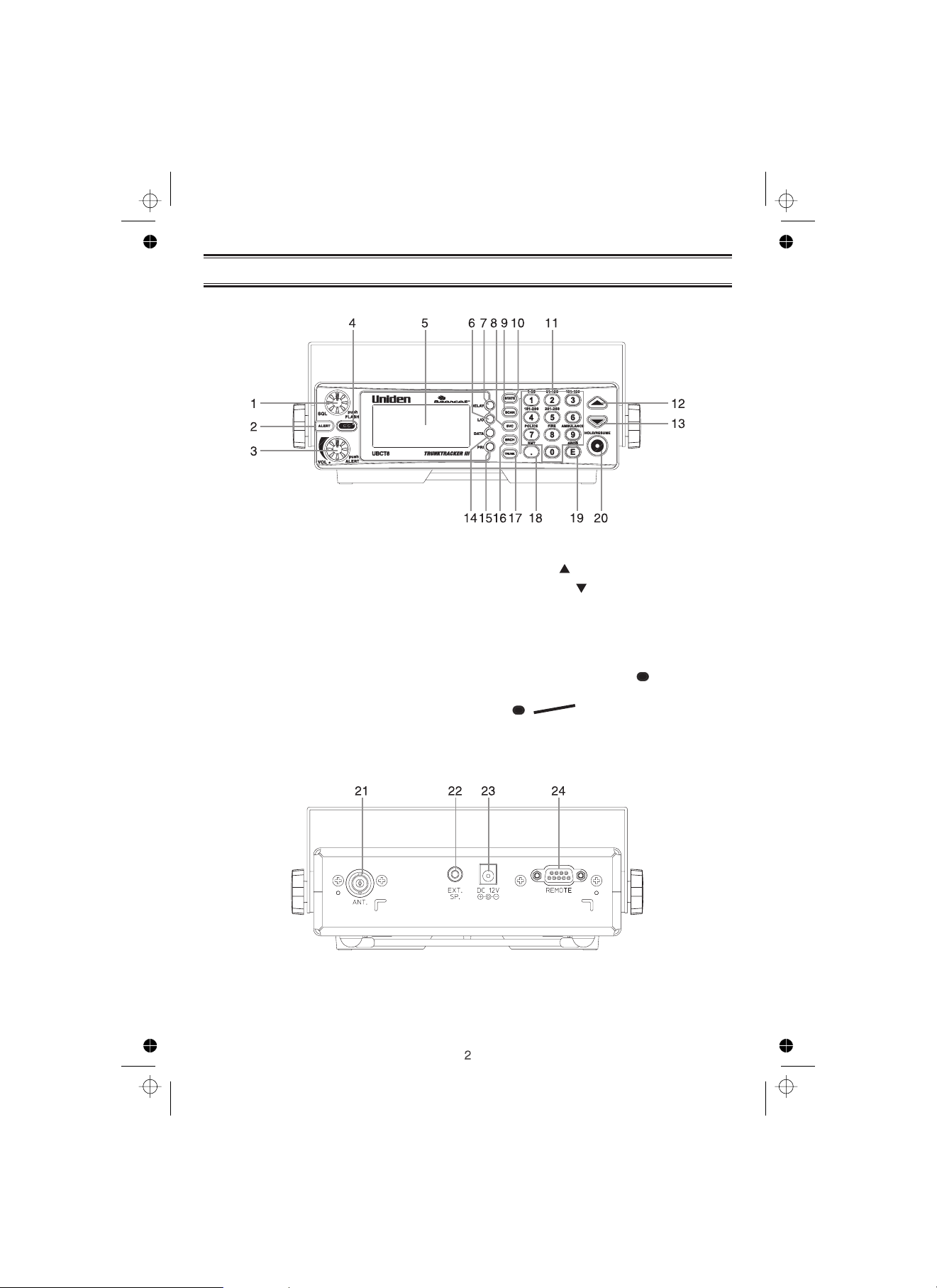
Front and Rear Views
1. Squelch Control / Flash Brightness
Selector
2. Alerting Light
3. Volume Control / Alert Tone Selector
(VOL)
4. Close Call RF Capture
5. Display
6. Lockout Key
7. Delay Key
8. Service Key
9. State Scan or Private Scan Key
(SCAN)
10. State Key
(SQL, FLASH)
(ALERT)
(C.C.)
(L/O)
(DELAY)
(SVC)
(STATE)
11. Numeric Keypad
12. Up Key
13. Down Key
14. Data Key
15. Priority Key
16. Search Key
17. Trunk Key
18. Decimal/Remote Key
19. Enter / Program Enable - Disable Key
( , PROG)
20. Hold/Resume Key
()
()
(DATA)
(PRI)
(SRCH)
(TRUNK)
( , RMT)
E
(HOLD/RESUME)
21. Antenna Connector
22. External Speaker Jack
(ANT.)
(EXT. SP.)
23. DC Power Jack
24. Remote Control Terminal
(DC 12V)
(REMOTE)
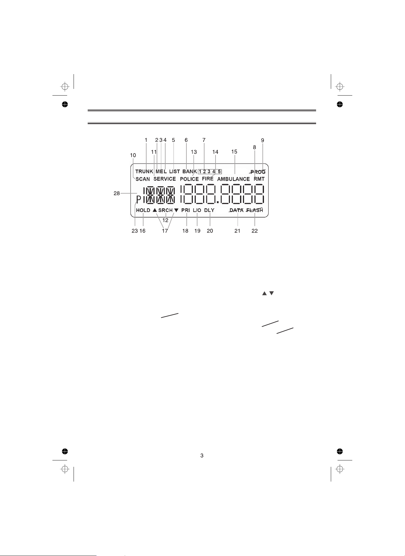
Icon Display
1. Trunk Tracking Mode
2. Motorola trunking channel
3. EDACS trunking channel
4. LTR trunking channel
5. Scan list
6. Scan bank
7. Bank's number and ID's list number
(12345)
8. Remote control mode
9. Programming is locked
10. State scanning and Private scanning
mode
11. Service scanning mode
12. Band searching mode
13. POLICE Bank included with State
scanning
(LIST)
(BANK)
(SCAN)
(POLICE)
(TRUNK)
(M)
(E)
(L)
(RMT)
(PROG)
(SERVICE)
(SRCH)
14. FIRE Bank included with State
scanning
15. AMBULANCE Bank included with
State scanning
16. Scanning or the searching is on hold
(HOLD)
17. Search direction
18. Priority function option
19. Lockout channel and talk group
20. Delay option
21. DATA Skip option
22. Warning Light disabled
23. Priority channel and talk group
(FIRE)
(AMBULANCE)
()
(PRI)
(L/O)
(DLY)
(DATA)
(FLASH)
P)(

Terminology
What is Scanning?
Unlike standard AM or FM radio stations, most two-way communications do not transmit
continuously. The UBCT8 scans the Frequencies you have programmed into the Scanner’s
channels until it finds an active frequency.
Scanning stops on an active frequency and remains on that channel as long as the
transmission continues. When the transmission ends, the scanning cycle resumes until
another transmission is received.
What is Searching?
The UBCT8 can search each of its 12 bands to find active frequencies. This is different from
scanning because you are searching for frequencies that have not been programmed into
your Scanner’s channels. The scanner automatically chooses between two speeds while
searching. During search mode the scanner will search 100 frequencies per second for band
with 12.5 kHz steps and during Turbo SEARCH mode the scanner can achieve up to 300
frequencies per second for bands with 5 kHz steps.
What is Trunk Tracking?
Conventional scanning is a simple concept. You enter a radio frequency in your scanner’s
memory which is used by someone you want to monitor. For example, the police in your
area may broadcast on MHz, the fire department on MHz, etc.
So when your scanner stops on a frequency, you usually know who it is, and more
importantly, you can stop on a channel and listen to an entire conversation.
467.850 161.250
As the demand for public communications has increased, many public radio users don't
have enough frequencies to meet their needs, and this has created a serious problem.
Trunking radio systems have been implemented to solve this problem.
In a trunked radio system the frequencies are shared among the police and fire departments
and a computer systematically assigns available frequencies when they are needed for
communications.

Sharing of the available public service frequencies, or trunking, allows cities, counties, or
other agencies to accommodate hundreds of users with relatively few frequencies. Following
a conversation on a trunked system using a scanner is difficult, if not impossible. Because
when there's a short break during the conversation you're monitoring, it’s possible that the
talkgroup will be assigned to a completely different frequency in the trunked system. This
type of scanning is difficult and frustrating.
TrunkTracker Technology
a conventional scanner, it actually follows the users of a trunked radio system. Once you
know a talkgroups ID, you won’t miss any of the action.
If you're a new scanner enthusiast, you may want to read the first part of this manual and
use your scanner in conventional mode before you begin trunk tracking. Understanding
scanning fundamentals and its terminology will make trunk tracking much easier.
changes this! Not only does your new UBCT8 scan channels like

Feature Highlights
!
Pre-programmed frequencies specific to each
!
Pre-programmed Trunked frequencies
!
Close Cal RF Capture Technology
You can set the scanner so it detects and provides information about nearby radio
transmissions.
!
Pre-programmed Service Scanning by the following service banks;
- Police
- Rail Roads
- Aircraft (except Aeronautic radio Navigation (108-117.9875MHz)
- Marine Band
- UHF CB Radio
- AM CB Radio
™
Australian state and New Zealand
!
Trunk Tracking
service systems just as if conventional two-way communications were used.
!
Multi-Track
trunked systems at the same time.
!
250 Channels
channel programmed to use the Scan mode.
!
12 Bands
!
5 Banks
maintain faster scanning cycles or for storing all the frequencies of a trunked system.
!
25 MHz-1300 MHz
bands of your scanner.
Note: The frequency coverage is not continuous.
!
5 Priority Channels
priority channel allows you to track activity on your most important channel(s) while
monitoring other channels for transmissions. You can also assign trunking priority
talkgroups.
!
Data Skip
birdies.
!
Direct Channel Access
mode.
!
Turbo Search
transmission bands with 5 kHz steps.
!
PC Programmable
Groups into your BCT8 through Uniden UBCT8 Scanning software running on your PC.
– For more information on UBCT8 SS Programming software visit our website at
www.uniden.com.au, www.uniden.co.nz
– Follow VHF High Band UHF 800MHz trunked public safety and public
– Track more than one trunking system at a time. Scan conventional and
– Program one frequency into each channel. You must have at least one
– Includes 12 bands, with aircraft and 800 MHz.
– 5 banks with 50 channels each are useful for storing similar frequencies to
– Indicates the range of frequencies that can be searched within the
– You can assign one priority channel in each bank. Assigning a
– Allows your scanner to skip unwanted data transmissions and reduces
– Go directly to any channel without entering programming
– Increases the search speed to 300 steps per second. This applies only to
– Allows you to easily program all frequencies and Trunking Talk

Included with Your Scanner Package
!
UBCT8 Scanner
!
AC Adapter
!
DC Power Cord
!
Cigarette Lighter Adapter Plug
!
Telescopic Antenna
!
Window Mount Antenna
!
Operating Guide
!
Other Printed Materials
!
Mobile Mounting Bracket
If any of these items are missing or damaged, immediately contact your place of purchase.
Optional Accessories
The following optional accessories for your UBCT8 are available from your local Uniden
Retailer.
Motorola Antenna Adapter
- Use only if your antenna has a Motorola-type plug.

Installing the UBCT8
For Home Use (Desktop Installation)
1. Insert the DC plug end of the AC Adapter into the DC 12V jack on the rear panel.
2. Plug the AC Adapter into a standard 240V AC wall outlet.
3. Plug the Telescoping Antenna into the ANT connector.
Extend the antenna to its full height. For frequencies higher than 406 MHz, shortening
the antenna may improve the reception.
4. Use the desktop stand for a better viewing and operating angle.
Helpful Hints
• If strong interference or electrical noise is received, relocate the scanner or its antenna
away from the source.
• If you are operating the scanner in a fringe area or need to improve reception, use an
optional antenna designed for multi-band coverage. (You can purchase this type of
antenna at a local electronics store.)
• If the optional antenna has no cable, use 50-70 ohm coaxial cable for lead-in. A mating
plug may be necessary for the optional antennas.
For Mobile Use (In-Car Installation)
Installation for Temporary Use:
A Cigarette Lighter Power Cord is provided for easy, temporary installation.
Warning:
Plug one end of the Cigarette Lighter Power Cord into the cigarette lighter jack and the other
end into the DC 12V jack on the back of the scanner.
Connecting the Antenna Plug
Connect the mobile antenna plug into the ANT connector on the rear panel. (For more
information on antenna installation, please refer to the instruction guide that came with your
antenna.)
The UBCT8 can be mounted using the supplied mounting bracket.
1. Select an ideal location in your vehicle to mount the UBCT8. Avoid a location that could
2. Use the supplied mounting bracket as a template for marking the location of the
Do not use the cigarette lighter power cord in a positive ground vehicle.
interfere with your driving. In a passenger car, the ideal location is underneath the
dashboard on the passenger side.
mounting screws. Note: If there are screws already holding the dashboard, you can use
the same screw holes to mount the bracket.

3. Drill the necessary holes and secure the mounting bracket in place using the screws
provided.
4. Mount the radio to the bracket only after the wiring has been connected to the rear
panel.
Connecting the Power Cord
Note:
Installation for everyday use:
1. Check the vehicle battery connections to determine which battery terminal (positive or
2. Connect the RED wire of the DC power cord to the accessory contact in your vehicle’s
3. Connect the BLACK wire of the DC power cord to the negative side of the vehicle
Note:
4. Insert the DC plug into the DC 12V jack on the back of the scanner.
If you are not experienced in connecting accessories to the vehicle fuse box, please
see your automotive dealer for advice on proper installation.
negative) is grounded to the engine block or chassis. Most of today’s vehicles use a
negative ground. If your vehicle has a negative ground, follow Steps 2 and 3. Otherwise,
skip to the note following Step 3.
+12V DC fuse box.
(usually the chassis).
In vehicles with a positive ground, the RED wire connects to the chassis and the
BLACK wire connects to the accessory contact in the fuse box.
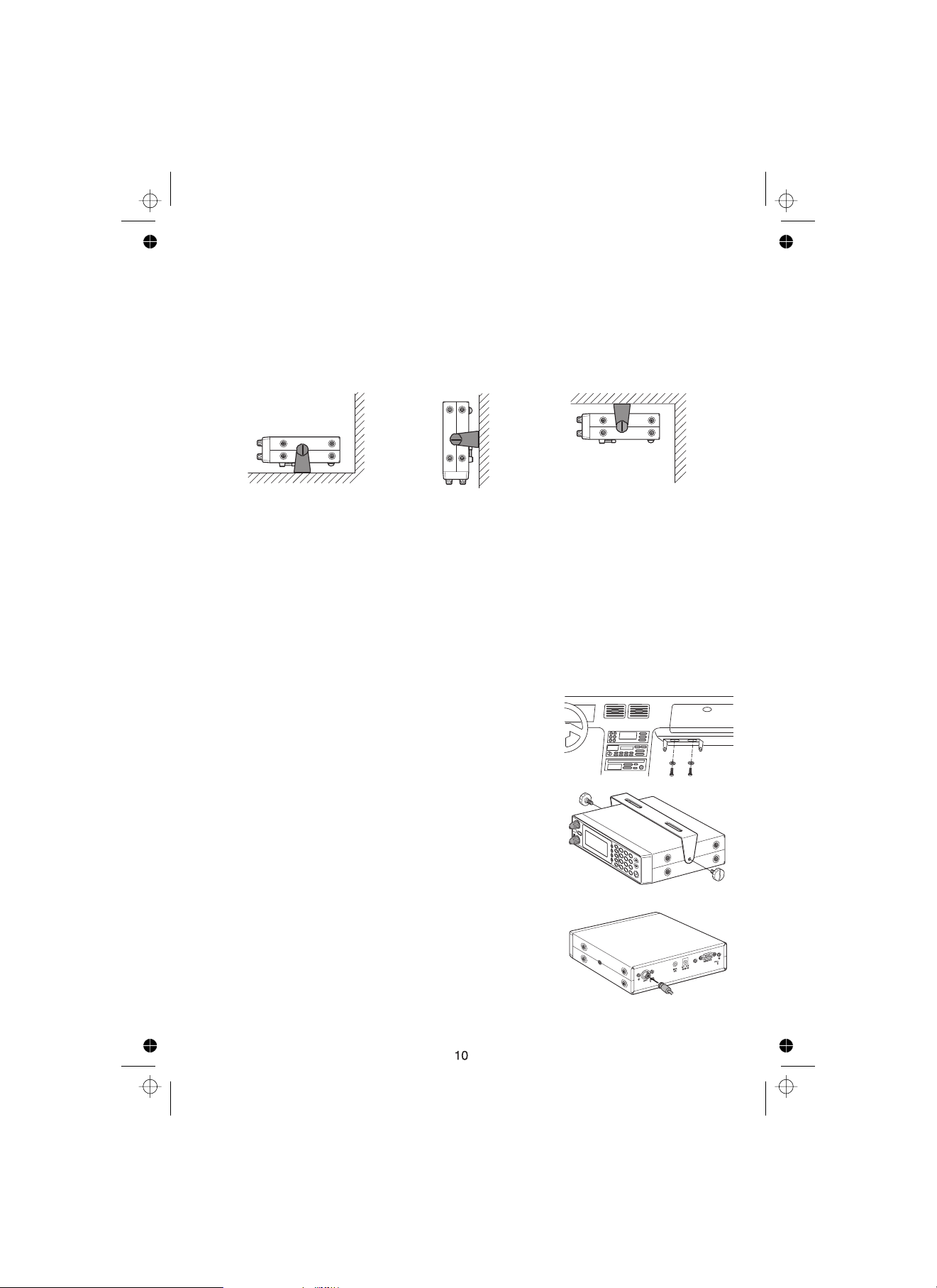
Typical Mounting Methods
The UBCT8 can be conveniently mounted on a table, bulkhead, overhead, or any other
desired location with the supplied mounting bracket (refer to figure below for typical
mounting methods).
Caution:
Make sure there are no hidden electrical wires or other items behind the desired
location before proceeding. Check that free access for mounting and cabling
is available.
• Table top mount • Bulkhead mount • Overhead mount
Mounting the Scanner in Your Vehicle
Before you mount the scanner, make sure you have all the necessary materials. Then
confirm that the scanner fits your vehicle’s mounting area. This unit requires a mounting
area of
Caution:
Follow these steps to mount the scanner in your vehicle.
1. Choose a mounting location, then use the supplied
2. In the marked positions, drill holes slightly smaller
50.8mm high by 176.5mm wide by 153.6mm deep.
Be sure to avoid obstructions behind the mounting surface.
mounting bracket as a template to mark the positions
for the mounting screw holes.
than the supplied screws.
3. Attach the mounting bracket to the mounting location
using the supplied screws and lock washers.
4. Attach the scanner to the mounting bracket using the
supplied mounting knobs.
5. Connect the antenna’s cable to the . connector
on the rear of the scanner.
Note: If the antenna cable’s connector does not fit in
the connector, you might also need a
ANT.
Motorola-to BNC antenna plug adapter
(available at a local electronics store).
ANT
Applying Power for Vehicle Installation
You can power your scanner using the supplied DC cigarette lighter power cord or an DC
power cord.
DC power Installation
To power the scanner from a vehicle’s 12V power source (such as a cigarette-lighter
socket), you need a cigarette-lighter adapter.
To connect an DC cigarette-lighter power cable, insert its barrel plug into the
DC 12V
cigarette lighter socket.
jack on the rear of the scanner, then plug the power cable into your vehicle’s
Note :
Caution:
!
!
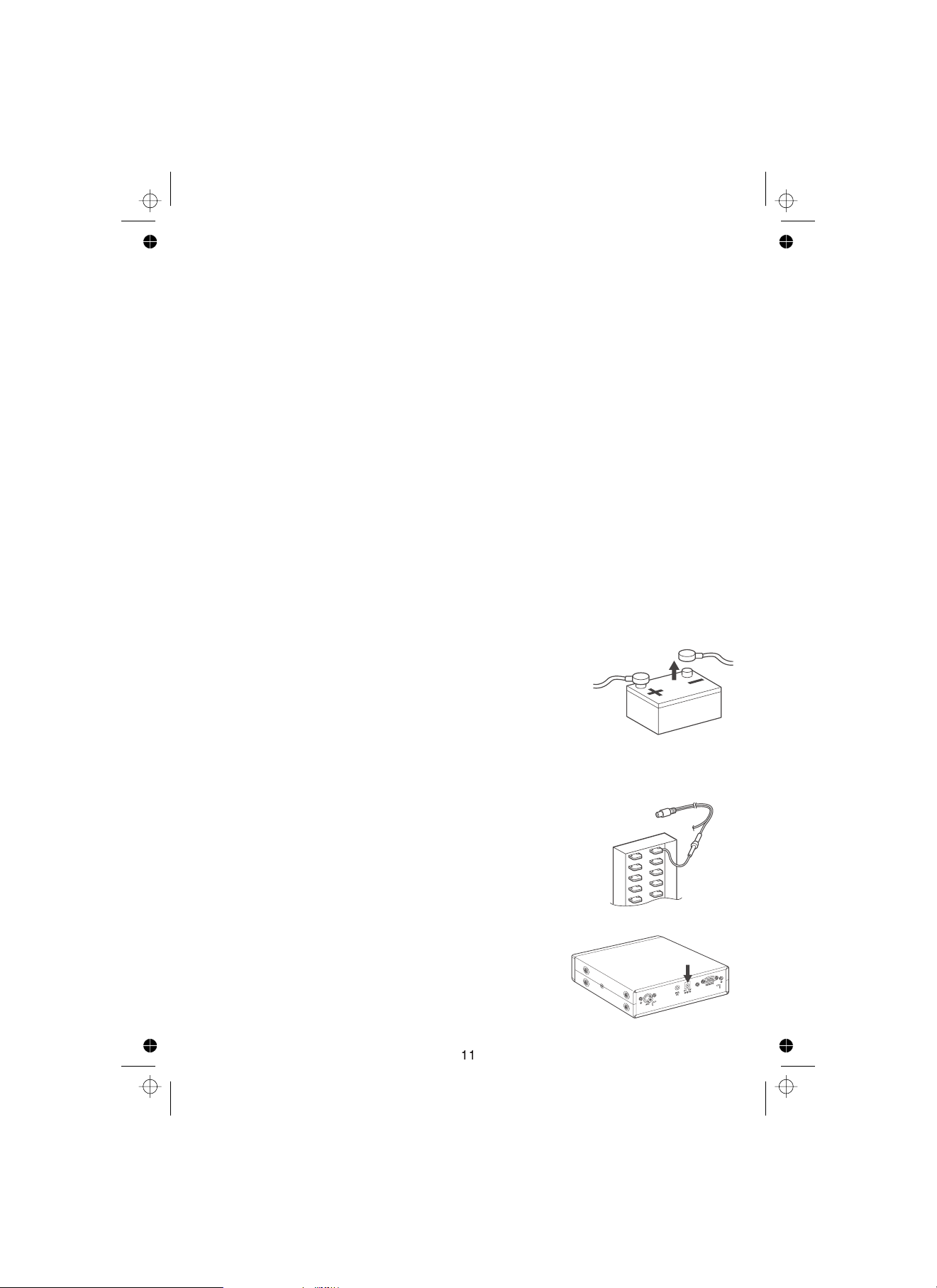
Follow these steps to connect the DC power cord.
1. Connect the power cord’s black wire to a chassis ground, such as a metal screw
2. Connect the power cord’s red wire (with in-line fuse) to a source
3. Insert the power cord’s barrel plug into the jack on
If you use a cigarette-lighter power cable and your vehicle’s engine is running, `
you might hear electrical noise from the engine while scanning. This is normal.
DC 12 V Jack can use a power source that supplies 12V DC at least
500 mA. You must use a power source that supplies 12V DC and delivers at least
500 mA. Your standard 12V car battery should be sufficient. The cord connector’s
center tip must be set to positive and its plug must fit the scanner’s jack.
The supplied DC power cord meets these specifications. Using a power cord that
does not meet these specifications could damage the scanner or the adapter.
Always connect the adapter or DC power cord to the scanner before you connect it to the
power source. When you finish, disconnect the adapter or DC power cord from the
power source before you disconnect it from the scanner.
For added safety and to protect your scanner,
disconnect the cable from your vehicle battery’s
negative (-) terminal before you begin.
attached to a metal part of the vehicle’s frame. Be sure that the screw is not insulated
from the frame by a plastic part.
of voltage that turns on and off with the ignition switch, such as
a spare accessory terminal in your vehicle’s fuse box.
DC 12V
the rear of the scanner.
DC 12V
4. Reconnect the cable to the vehicle battery’s negative (-)
terminal.

Applying Power Using Standard AC Power
To power the scanner from an AC outlet, use the provided AC adapter with a 5.5 mm outer
diameter/2.1mm inner diameter tip.
Caution:
!
1. Insert the adapter’s barrel plug into the
2. Plug the adapter into a standard AC outlet.
Note:
You must use a Class 2 power source that supplies 12V DC and delivers at least
500 mA. The cord connector’s center tip must be set to positive and its plug must
fit the scanner’s jack. Using an adapter that does not meet these specifications could damage the scanner or the adapter.
Always connect the AC adapter to the scanner before you connect it to AC power. When
you finish, disconnect the adapter from the AC power before you disconnect it from
the scanner.
DC 12V
jack on the rear of the scanner.
Use only the AC adapter supplied with
your scanner.
DC 12V
Connecting an External Speaker
In a noisy area, an external speaker (available at a local electronics store) positioned in the
right place might provide more comfortable listening.
Plug the speaker cable’s 1/8 inch (3.5 mm)
plug into your scanner’s . jack.
Note:
Connecting an external speaker
disconnects the scanner’s
internal speaker.
EXT. SP
Listening Safely
!
Do not use the earphone. The volume is not adjustable for the Warning Alert and
damage to your hearing could occur.
Connecting the Clone Cable
You can transfer the programmed data to and from another UBCT8 scanner using a RS232C
Straight Cable (9 pin to 9 pin) (not supplied). Connect the cable between each scanner’s
REMOTE
programmed data to or from a PC using optional programming software available through
your local electronics store.
jacks. See "Clone Mode" on page 49. You can also upload or download the

Scanning Overview
You can scan in one of five ways:
1. Close Call RF Capture
strong radio frequencies. You may run Close Call in the background of any of the four
options below or on its own.
2. Service Scanning
frequency. Police, Railroad and AM CB service frequencies are valid for Australia only.
Aircraft, Marine and UHF CB service frequencies are valid for both Australia and
New Zealand.
Band Search Select a frequency band to search. The Search function is different from
3.
scanning. It searches for any active frequency step by step within the lower and upper
limits of the band. When an active frequency is found, the scanner will stop and stay on
that frequency as long as that transmission lasts. If that frequency is interesting to you,
press to hold the frequency on the display. Then program it into the
HOLD/RESUME
private bank you want to store. If you do not want to program that frequency, press
HOLD/RESUME
automatically 2 seconds after the last transmission and looks for more active
frequencies.
4. SCAN,
Private Scanning
1, 2, 3, 4 5
then or to scan only those that you have programmed in this bank.
5.
State Scanning
pre-programmed on a Australian state by state (including New Zealand) basis.
Note:
When scanning stops on an active frequency, it remains on that
channel as long as the transmission continues. When the
transmission ends, the scanner will remain on the same
channel for 2 more seconds, waiting for a responding
transmission. If there is no responding transmission within 2
seconds, the scanning cycle resumes.
Before you can scan the Private Bank, you must program frequencies into the
channels. To program frequencies, see “Programming Frequencies into Channels”
on page 21.
or just wait until the transmission ends. The search resumes
You can select Police, Fire and Ambulance frequencies which are
When you activate Close Call your scanner will detect nearby
SVC
Press to select one of the six services to find an active
If you have programmed frequencies into this bank, press
Turn the Scanner On
1. Turn the knob clockwise.
The scanner is turned on: the Alert Light flashes and the Alert
Tone beeps loudly.
Note:
2. While the alert tone sounds the display shows 'ubct8'.
When this stops the last setting mode selected before starts.
VOL
The Alert Tone depends on the currently setting selected
(see page 20).
CC
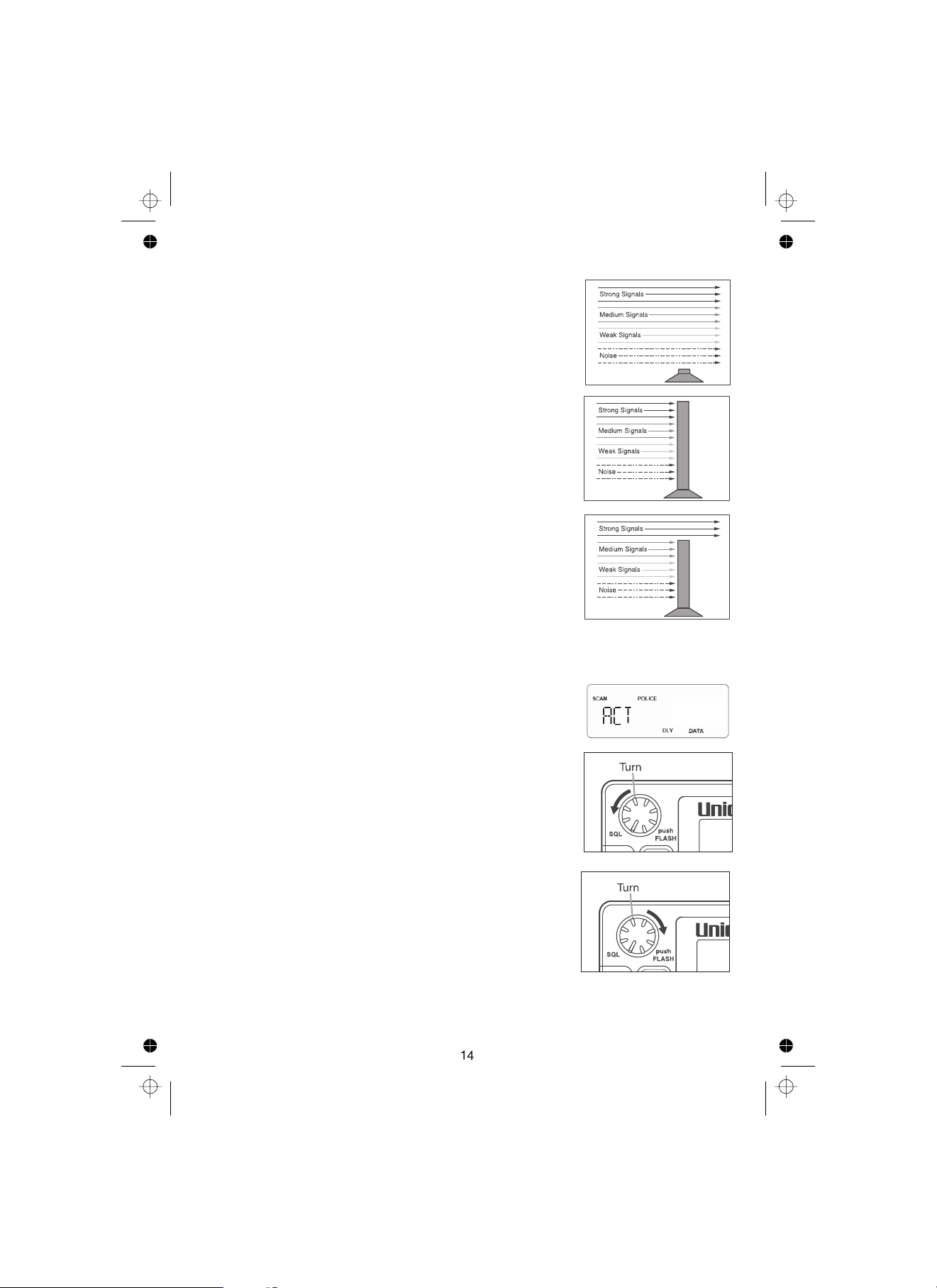
How Squelch Works
Think of “SQUELCH” as a gate. If the gate is too low (squelch
too low), everything (all noise as well as signals) gets through.
If the gate is set too high (squelch too high), nothing gets
through.
If the gate is set just right (squelch set properly), just the
desired signals get through.
Setting the Squelch
1. To set the squelch, press to stop
scanning.
2. Turn fully counterclockwise until hiss heard.
3. Turn fully clockwise just until hiss stops.
SQL
This lowers the “squelch gate,” allowing all signals and
noise to get through.
SQL
This raises the “squelch gate,” allowing only strong signals
to get through.
HOLD/RESUME
467.8500
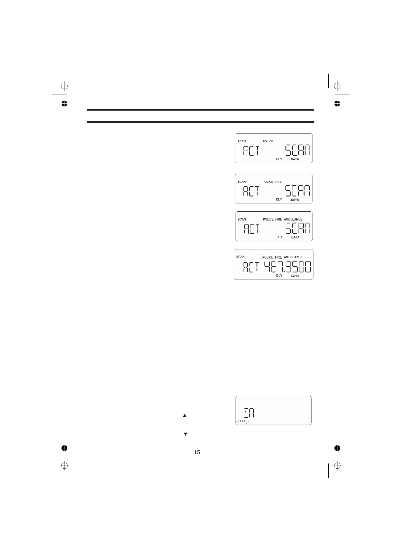
State Scanning
POLICE, FIRE AMBULANCE
Press or and the
scanner scans through police, fire or
Ambulance Frequencies and "SCAN" scrolls from
right to left in the display.
When in the State Scan mode, press and
the menu of states will appear.
POLICE.
Press
The scanner will scan through Factory
Programmed Police Frequencies and
appears in the display.
FIRE.
Press
The scanner will scan through Factory
Programmed Fire Frequencies and
appears in the display.
AMBULANCE.
Press The scanner will scan
through Factory Programmed Ambulance
Frequencies, appears in the
display.
”AMBULANCE”
STATE
”POLICE”
”FIRE”
When the scanner finds a signal, scanning stops, the state code and the frequency displays.
When the transmission ends, the two seconds delay feature (if you set on) holds the scanner
on that frequency for a response. If there is no response, scanning resumes. (See Delay
page 28)
Selecting the State
1. While State scanning, press . The menu of
states will appear (See State Code Order Appendix:
page 56).
2. Press and hold to scroll.
3. To step forward through the states (A-W), press
STATE
4. To step backward through the states (W-A), press
STATE
and, within 3 seconds, press repeatedly.
and, within 3 seconds, press repeatedly.
STATE
STATE
5. To scroll repeatedly, press and hold or and
STATE
.
After 3 seconds, the scanner will begin to scan
through the Police frequencies (Police only).
6. If you want to start scanning immediately, press
HOLD/RESUME
.
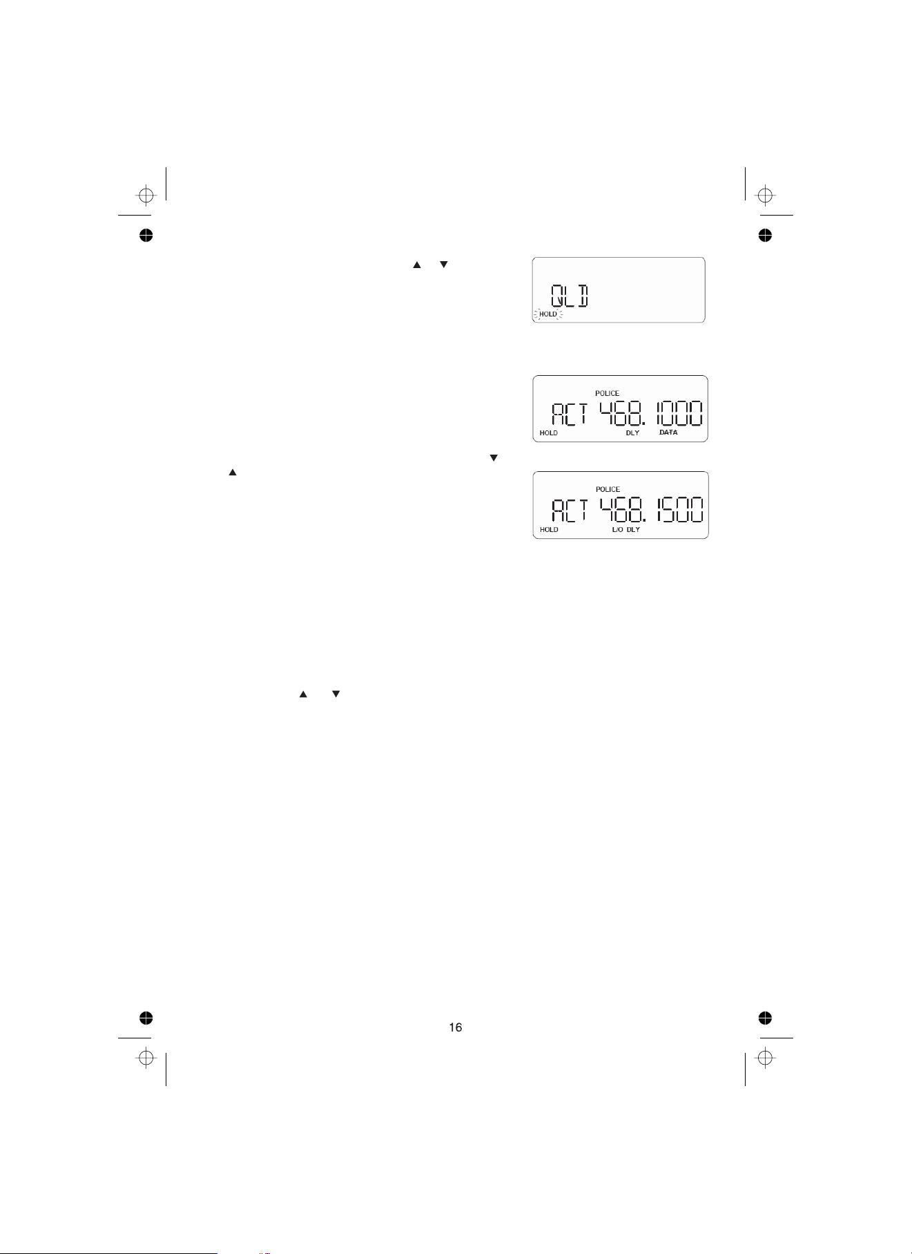
State Scan Hold
1. When scanning stops on a desired frequency, press
HOLD/RESUME
you like.
”HOLD”
While appears in this mode, you can use
or to move up or down the frequency steps.
During Hold mode, you can see all frequencies
sequentially. It does not depend on your selected
bank.
Pressing and holding the keys for 1 sec, speeds up
frequency change.
If present frequency is locked out, then appears
on LCD.
2. To resume scanning, press .HOLD/RESUME
to hold at that frequency as long as
”L/O”
Storing State Scan Frequencies
You can quickly store any frequency you find during scan.
1. During scan, press to store.
You can press or to move up or down 1 frequency step.
2. If you have found the frequency you want to store, press .
- Or-
When the scanner stops on the frequency you want to store, press .E
3. Select the private bank where you want to store the frequency, the smallest empty
channel number and "000.0000" flashes on and off over the frequency you want to store.
Press (if the frequency you want to store exists already in a bank, you will hear an error
E
tone and the other channel displays. Press again to store the frequency in both
channels).
HOLD/RESUME
E
E
Skip a frequency
To skip a frequency, press . You can program up to 100 skip frequencies.
You can skip the frequencies in the scanning sequence.
If you change the state code, skipped frequencies are canceled as soon as scanning starts.
If you change the State, skip frequencies are all clear.
L/O
Close Call RF Capture
Your scanner's Close Call feature lets you set the scanner so it detects then displays the
frequency of a nearby strong radio transmission. Close Call RF capture works great for
finding frequencies at venues such as malls and sporting events. You can set the scanner so
Close Call detection works “in the background” while you are scanning other frequencies,
turn off normal scanning while Close Call is working, or turn off the Close Call feature and
use the scanner normally. You can set the scanner so it alerts you when the Close Call
feature detects a frequency. You can also set the frequency band where you want the
scanner to look for transmissions.
Unlike searching, which requires the scanner to tune to a frequency to check for a
transmission, Close Call RF capture directly detects the presence of a strong, nearby signal
and instantly tunes to the source's frequency.
Notes:
Close Call RF capture works well for locating the source of strong local transmissions such
as mobile and handheld two-way radios in areas with no other strong transmission sources.
However, if you are in an area with many transmission sources (such as pager radio
transmitters, multi-use radio towers, traffic control devices, etc.), Close Call RF capture might
not find the transmission you are searching for, or it might find a transmission other than the
one you are searching for.
Close Call RF capture cannot detect satellite dishes or any transmitter with a frequency
above or below the frequency ranges listed in Select Close Call Bands on Page 19.
Close Call works better with some types of transmissions than others. It might not correctly
display frequency information for transmitters using a highly directive antenna (such as an
amateur radio beam antenna), if there are many transmitters operating at the same time in
the same area, or if the transmitter is a broadcast television station.
TM
Every 2 seconds, the scanner checks for frequencies in the range you specified in "Set Close
Call Option" on page 19 and interrupts the audio when it checks for a Close call Transmission
in that range.
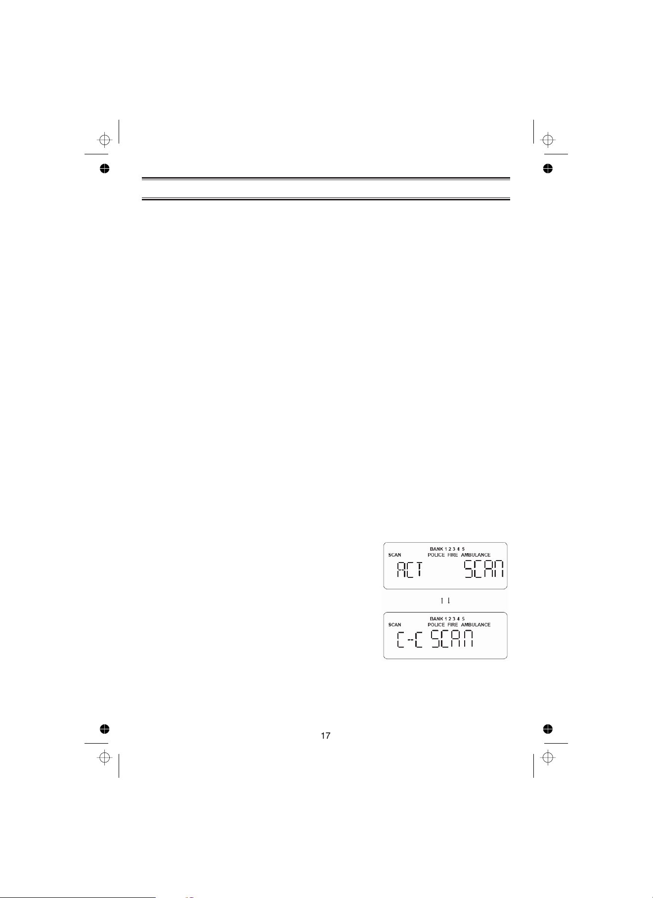
Set Close Call Mode
These settings affect when Close Call actually operates.
When Close Call is on with another mode, every 2
seconds the scanner will switch the filter settings to
the ones set by the Close Call Bands option.
!
Close Call: On Close Call is on at all times, for all
modes.
!
Close Call: Off Close Call is turned off for all modes.
!
Close Call: Only Close Call is only available.
These modes can also be toggled by pressing
When Close Call is set to On, Close Call LED is On.
When Close Call is set to only mode, Close Call LED will
flash.
When Close Call is set to off, Close Call LED is Off.
When Close Call is on, “C-C” will be displayed every a
few seconds.
C.C.
 Loading...