

Page 1

UBCD396XT
OWNER’S MANUAL
Page 2

NOTE ON COLOURED TEXT:
• Sections within this document are numbered to help you
navigate the content.
• Text within the sections which are coloured blue indicate more
information about the indicated text may be available as a
section of the same name. Refer to the table of contents to
navigate to these sections.
• Text within the sections which are underlined and coloured blue
(not including the section headers) may be hyperlinked to that
specific section or website.
Page 3

Table of Contents
1. GENERAL PRECAUTIONS ............................................................................................................ 1
EARPHONE WARNING ............................................................................................................................... 1
LIQUID EXPOSURE WARNING .................................................................................................................... 1
POWER DISCONNECTION CAUTION ........................................................................................................... 1
2. SETTING UP THE HARDWARE .................................................................................................... 2
WHAT'S INCLUDED INSIDE THE BOX? ........................................................................................................ 2
INSTALL THE BATTERIES ........................................................................................................................... 3
CONNECT THE ANTENNA ........................................................................................................................... 3
ATTACH THE BELT CLIP ............................................................................................................................. 4
3. CONNECTING A GPS RECEIVER ................................................................................................. 5
COMPATIBLE GPS RECEIVERS .................................................................................................................. 5
CONFIGURING YOUR SCANNER .................................................................................................................. 5
CONNECTING THE RECEIVER ..................................................................................................................... 5
TROUBLESHOOTING .................................................................................................................................. 6
4. USING PRELOADED SYSTEMS .................................................................................................... 7
PRELOADED SYSTEMS ............................................................................................................................... 7
5. AVAILABLE OPERATION MODES ............................................................................................... 8
SCAN MODE ............................................................................................................................................... 8
SEARCH MODE ........................................................................................................................................... 8
HOLD MODE .............................................................................................................................................. 8
CLOSE CALL PRIORITY MODE .................................................................................................................... 8
CLOSE CALL ONLY MODE .......................................................................................................................... 9
CLOSE CALL DO NOT DISTURB MODE ....................................................................................................... 9
PRIORITY SCAN MODE ............................................................................................................................... 9
PRIORITY PLUS SCAN MODE .................................................................................................................... 10
GPS MODE .............................................................................................................................................. 10
TONE OUT MODE ..................................................................................................................................... 10
BAND SCOPE MODE ................................................................................................................................. 10
6. KEYS AND THEIR FUNCTIONS ................................................................................................. 11
KEY OVERVIEW ....................................................................................................................................... 11
OPERATING THE CONTROLS .................................................................................................................... 12
Using the FUNCTION button .......................................................................................................... 12
KEY FUNCTIONS IN DIFFERENT OPERATION MODES ................................................................................ 12
i
Page 4

UBCD396XT
LOCKING THE KEYPAD ............................................................................................................................ 13
7. MENU TREE .................................................................................................................................. 14
MAIN MENU ............................................................................................................................................. 14
USING THE MENU .................................................................................................................................... 14
8. READING THE DISPLAY ............................................................................................................. 15
SPECIAL DISPLAYS................................................................................................................................... 18
9. CONVENTIONAL SYSTEMS ........................................................................................................ 19
PROGRAMMING A CONVENTIONAL SYSTEM ............................................................................................. 19
Create a system ................................................................................................................................. 19
Create at least 1 channel group ........................................................................................................ 20
Create at least 1 channel in each group ........................................................................................... 20
10. EDACS SCAT SYSTEMS ........................................................................................................... 24
PROGRAMMING AN EDACS SCAT SYSTEM ............................................................................................ 24
Create a system ................................................................................................................................. 24
Create a site ....................................................................................................................................... 25
Create at least 1 frequency ............................................................................................................... 25
11. EDACS TRUNKED SYSTEMS .................................................................................................. 28
PROGRAMMING AN EDACS SYSTEM ....................................................................................................... 28
Create a system ................................................................................................................................. 28
Create at least 1 site ......................................................................................................................... 29
Create at least 1 frequency in each site ........................................................................................... 30
PROGRAMMING A SYSTEM FOR SCANNING .............................................................................................. 31
Create at least 1 channel group ........................................................................................................ 31
Create at least 1 channel in each group ........................................................................................... 31
12. LTR TRUNKED SYSTEMS ........................................................................................................ 36
PROGRAMMING AN LTR SYSTEM ............................................................................................................ 36
Create a system ................................................................................................................................. 36
Create at least 1 site ......................................................................................................................... 37
Create at least 1 frequency in each site ........................................................................................... 38
PROGRAMMING A SYSTEM FOR SCANNING .............................................................................................. 38
Create a channel group ..................................................................................................................... 39
Create a channel in each group ........................................................................................................ 39
13. MOTOROLA TRUNKED SYSTEMS ......................................................................................... 42
PROGRAMMING A MOTOROLA SYSTEM .................................................................................................... 42
Create a system ................................................................................................................................. 42
ii
Page 5

UBCD396XT
Create at least 1 site ......................................................................................................................... 43
Create at least 1 frequency in each site ........................................................................................... 44
PROGRAMMING A SYSTEM FOR SCANNING .............................................................................................. 44
Create a channel group ..................................................................................................................... 45
Create a channel ................................................................................................................................ 45
14. MOTOROLA FLEET MAPS ....................................................................................................... 50
PRESET FLEET MAPS .............................................................................................................................. 50
CUSTOM FLEET MAPS ............................................................................................................................. 50
HOW FLEET MAPS WORK ........................................................................................................................ 51
Blocks ................................................................................................................................................. 51
Size Codes .......................................................................................................................................... 52
15. STANDARD P25 TRUNKED SYSTEMS ................................................................................... 53
PROGRAMMING A P25 SYSTEM ................................................................................................................ 53
Create a system ................................................................................................................................. 53
Create at least 1 site ......................................................................................................................... 54
Create at least 1 frequency in each site ........................................................................................... 54
PROGRAMMING A SYSTEM FOR SCANNING .............................................................................................. 55
Create a channel group ..................................................................................................................... 55
Create a channel in a group .............................................................................................................. 56
16. SINGLE-FREQUENCY P25 TRUNKED SYSTEMS ................................................................. 59
PROGRAMMING A SINGLE-FREQUENCY P25 SYSTEM .............................................................................. 59
Create a system ................................................................................................................................. 59
Create exactly 1 site .......................................................................................................................... 60
PROGRAMMING A SYSTEM FOR SCANNING .............................................................................................. 60
Create a channel group ..................................................................................................................... 61
Create a channel ................................................................................................................................ 61
17. RADIO SYSTEMS OVERVIEW ................................................................................................. 63
CONVENTIONAL RADIO SYSTEMS ............................................................................................................. 63
TRUNKED RADIO SYSTEMS ...................................................................................................................... 63
Trunked system basics ...................................................................................................................... 64
How a trunked system works ........................................................................................................... 64
A real life example ............................................................................................................................. 65
18. DECIPHERING TRUNKED SYSTEMS .................................................................................... 66
BEFORE YOU PROGRAM A TRUNKED SYSTEM ........................................................................................... 66
System Type ....................................................................................................................................... 66
System Voice ...................................................................................................................................... 67
iii
Page 6

UBCD396XT
System Frequencies ........................................................................................................................... 68
Talk Group IDs (Channels) ............................................................................................................... 68
19. LOCATION-BASED SCANNING .............................................................................................. 69
THE GEOPOLITICAL APPROACH .............................................................................................................. 70
THE ANTENNA-CENTRIC APPROACH ....................................................................................................... 73
COMBINING FOR EFFICIENCY .................................................................................................................. 74
20. NUMBER TAGS ......................................................................................................................... 76
PROGRAMMING NUMBER TAGS ............................................................................................................... 76
Assigning an SNT .............................................................................................................................. 76
Assigning a CHNT ............................................................................................................................. 77
USING NUMBER TAGS ............................................................................................................................. 78
21. QUICK KEYS .............................................................................................................................. 79
PROGRAMMING QUICK KEYS .................................................................................................................. 79
Assigning an SQK ............................................................................................................................. 79
Assigning a GQK ............................................................................................................................... 80
USING QUICK KEYS ................................................................................................................................ 80
To use SQK 0 through 9 .................................................................................................................... 81
To use SQK 10 through 99 ................................................................................................................ 81
To use a GQK ..................................................................................................................................... 81
22. SEARCH KEYS ........................................................................................................................... 82
PROGRAMMING SEARCH KEYS ................................................................................................................ 82
USING SEARCH KEYS .............................................................................................................................. 82
23. PROGRAMMING LOCATIONS ................................................................................................. 83
PROGRAMMING A LOCATION FOR A SITE .................................................................................................. 83
PROGRAMMING A LOCATION FOR A CHANNEL GROUP .............................................................................. 83
PROGRAMMING GENERAL LOCATIONS ..................................................................................................... 83
To create a new location .................................................................................................................... 84
For Dangerous Xing and Dangerous Roads only ............................................................................. 85
Edit an existing location ................................................................................................................... 85
24. SETTING ALERTS ..................................................................................................................... 86
25. USING QUICK KEYS, STARTUP KEYS, AND SEARCH KEYS............................................. 88
QUICK KEYS ............................................................................................................................................ 88
STARTUP KEYS ........................................................................................................................................ 88
SEARCH KEYS ......................................................................................................................................... 88
26. TONE OUT MODE ..................................................................................................................... 89
iv
Page 7

UBCD396XT
CONFIGURING TONE OUT CHANNELS ..................................................................................................... 89
USING TONE-OUT MODE ........................................................................................................................ 89
KEY OPERATION IN TONE OUT MODE ..................................................................................................... 90
27. CLOSE CALL MODE ................................................................................................................. 92
KEY OPERATION IN CLOSE CALL ONLY MODE ......................................................................................... 92
28. BAND SCOPE MODE ................................................................................................................. 95
TO TURN ON BAND SCOPE MODE: ............................................................................................................ 95
KEY OPERATION IN BAND SCOPE MODE .................................................................................................. 96
29. GPS MODE ................................................................................................................................. 99
SEE ALSO ................................................................................................................................................ 99
READING THE DISPLAY IN GPS MODE ................................................................................................... 100
Main GPS display ............................................................................................................................ 100
Location alert display ...................................................................................................................... 100
Location review display ................................................................................................................... 101
KEY OPERATION IN GPS MODE ............................................................................................................. 102
30. PROGRAM SYSTEM ................................................................................................................ 105
EDIT NAME ........................................................................................................................................... 105
EDIT SYS OPTION .................................................................................................................................. 105
EDIT SITE .............................................................................................................................................. 105
EDIT GROUP .......................................................................................................................................... 106
COPY SYSTEM ....................................................................................................................................... 106
DELETE SYSTEM ................................................................................................................................... 106
NEW SYSTEM ........................................................................................................................................ 106
31. EDIT SYS OPTION ................................................................................................................... 107
GLOBAL SYSTEM OPTIONS ..................................................................................................................... 107
Set Number Tag .............................................................................................................................. 107
Set Delay Time ................................................................................................................................ 107
Set Audio AGC ................................................................................................................................. 107
CONVENTIONAL SYSTEM OPTIONS ......................................................................................................... 107
Set Quick Key .................................................................................................................................. 107
Set Startup Key ............................................................................................................................... 108
Set Lockout ...................................................................................................................................... 108
Set Hold Time .................................................................................................................................. 108
P25 Waiting Time ............................................................................................................................ 108
TRUNKED SYSTEM OPTIONS .................................................................................................................. 109
ID Scan/Search ................................................................................................................................ 109
v
Page 8

UBCD396XT
Priority ID Scan ............................................................................................................................... 109
Emergency Alert .............................................................................................................................. 109
Set ID Format (DEC/HEX) or (AFS/DEC) ..................................................................................... 109
Rvw ID:Srch L/O .............................................................................................................................. 110
Clr All L/O IDs ................................................................................................................................. 110
MOTOROLA SYSTEM OPTIONS ................................................................................................................ 110
Edit Fleet Map ................................................................................................................................. 110
Set Status Bit ................................................................................................................................... 110
Set End Code ................................................................................................................................... 110
P25 SYSTEM OPTIONS ........................................................................................................................... 110
P25 NAC Option .............................................................................................................................. 111
32. EDIT GROUP ............................................................................................................................ 112
OPTIONS AVAILABLE FOR ALL GROUPS: ................................................................................................. 112
Edit Name ........................................................................................................................................ 112
Set Quick Key .................................................................................................................................. 112
Edit Channel .................................................................................................................................... 112
Set LocationInfo ............................................................................................................................... 112
Set Lockout ...................................................................................................................................... 112
Delete Group .................................................................................................................................... 113
New Group ....................................................................................................................................... 113
33. SET LOCATIONINFO .............................................................................................................. 114
SET LATITUDE AND SET LONGITUDE .................................................................................................... 114
SET RANGE ........................................................................................................................................... 114
SET GPS ENABLE ................................................................................................................................. 114
34. EDIT CHANNEL ...................................................................................................................... 116
EDIT FREQUENCY (CONVENTIONAL SYSTEMS) ...................................................................................... 116
EDIT TALK GROUP ID (TRUNKED SYSTEMS).......................................................................................... 116
OPTIONS AVAILABLE FOR ALL CHANNELS: ............................................................................................ 116
Edit Name ........................................................................................................................................ 116
Set Audio Type ................................................................................................................................. 116
Set Number Tag .............................................................................................................................. 116
Set Modulation ................................................................................................................................ 117
Set Attenuator ................................................................................................................................. 117
Set Priority ....................................................................................................................................... 117
Set Alert ........................................................................................................................................... 117
Set Lockout ...................................................................................................................................... 117
Volume Offset .................................................................................................................................. 118
Copy Channel................................................................................................................................... 118
vi
Page 9

UBCD396XT
Delete Channel ................................................................................................................................ 118
New Channel ................................................................................................................................... 118
ANALOG CHANNEL OPTIONS .................................................................................................................. 118
Set CTCSS/DCS ............................................................................................................................... 118
DIGITAL CHANNEL OPTIONS .................................................................................................................. 119
P25 NAC Option .............................................................................................................................. 119
35. EDIT SITE ................................................................................................................................ 120
OPTIONS AVAILABLE FOR ALL SITES: ..................................................................................................... 120
Edit Name ........................................................................................................................................ 120
Set Quick Key .................................................................................................................................. 120
Set Startup Key ............................................................................................................................... 120
Set Frequencies ............................................................................................................................... 121
Set Modulation ................................................................................................................................ 121
Set Attenuator ................................................................................................................................. 121
Set Lockout ...................................................................................................................................... 121
Set Hold Time .................................................................................................................................. 121
Set LocationInfo ............................................................................................................................... 121
Delete Site ........................................................................................................................................ 122
New Site ........................................................................................................................................... 122
OPTIONS AVAILABLE FOR MOTOROLA SYSTEMS .................................................................................... 122
OPTIONS AVAILABLE FOR P25 SYSTEMS ................................................................................................ 122
Edit Band Plan (P25) ...................................................................................................................... 122
OPTIONS AVAILABLE FOR EDACS SYSTEMS ......................................................................................... 123
Set Site Type .................................................................................................................................... 123
Volume Offset (EDACS SCAT Only) .............................................................................................. 123
36. SET FREQUENCIES ................................................................................................................ 124
Edit Frequency ................................................................................................................................ 124
Set Lockout ...................................................................................................................................... 124
Delete Frequency ............................................................................................................................. 124
New Frequency ................................................................................................................................ 124
LTR AND EDACS SYSTEM OPTIONS ..................................................................................................... 124
LCN (Logical Channel Number) ..................................................................................................... 125
EDACS SCAT SYSTEM OPTIONS........................................................................................................... 125
Set Number Tag .............................................................................................................................. 125
Volume Offset .................................................................................................................................. 125
37. SCAN MODE ............................................................................................................................. 126
SCANNING VS. SEARCHING .................................................................................................................... 126
Scanning trunked systems .............................................................................................................. 126
vii
Page 10

UBCD396XT
Searching trunked systems ............................................................................................................ 126
DEFAULT SCAN MODE .......................................................................................................................... 126
LOCKED ITEMS ...................................................................................................................................... 127
KEY OPERATION IN SCAN MODE ............................................................................................................ 127
Special keys ...................................................................................................................................... 127
Keypad controls ............................................................................................................................... 128
KEY OPERATION IN SEARCH MODE ........................................................................................................ 131
Special keys ...................................................................................................................................... 131
Keypad controls ............................................................................................................................... 131
38. HOLD MODE ............................................................................................................................ 134
KEY OPERATION IN HOLD MODE ........................................................................................................... 134
READING THE DISPLAYS IN HOLD MODE ............................................................................................... 136
Conventional system display .......................................................................................................... 136
Trunked system display .................................................................................................................. 137
Service search with scan hold display ............................................................................................ 138
39. EDIT TALK GROUP ID ........................................................................................................... 139
MOTOROLA TYPE I SYSTEMS ................................................................................................................. 139
MOTOROLA TYPE II SYSTEMS ............................................................................................................... 139
P25 SINGLE FREQUENCY SYSTEMS OR STANDARD SYSTEM TRUNK SITE ............................................. 139
EDACS WIDE OR NARROW SYSTEMS ................................................................................................... 139
AFS format ....................................................................................................................................... 139
I-CALL CHANNEL (MOTOROLA, P25 OR EDACS) .................................................................................. 140
LTR SYSTEMS ....................................................................................................................................... 140
40. EDIT BAND PLAN ................................................................................................................... 141
CREATING A CUSTOM BAND PLAN .......................................................................................................... 141
Band plan number ........................................................................................................................... 141
Set Base Freq ................................................................................................................................... 141
Set Offset .......................................................................................................................................... 141
Set Spacing ...................................................................................................................................... 141
41. CALCULATING UPPER BASE FREQUENCIES ................................................................... 142
Custom Frequency Table ................................................................................................................ 142
42. CLOSE CALL ............................................................................................................................ 145
CLOSE CALL ONLY ................................................................................................................................ 145
CC AUTO STORE ................................................................................................................................... 145
HITS WITH SCAN ................................................................................................................................... 145
Set Quick Key .................................................................................................................................. 145
viii
Page 11

UBCD396XT
Set Number Tag .............................................................................................................................. 145
Set Lockout ...................................................................................................................................... 146
Set Hold Time .................................................................................................................................. 146
SET CC MODE ....................................................................................................................................... 146
SET CC OVERRIDE ................................................................................................................................ 146
SET CC ALERT ...................................................................................................................................... 146
SET CC BANDS ...................................................................................................................................... 147
43. PRIORITY SCAN ...................................................................................................................... 149
PRIORITY SCAN MENU ........................................................................................................................... 149
Set Priority ....................................................................................................................................... 149
Set Interval ...................................................................................................................................... 149
MaxCHs/Pri-Scan ............................................................................................................................ 150
44. PROGRAM LOCATION ............................................................................................................ 151
POI ....................................................................................................................................................... 151
Edit Name ........................................................................................................................................ 151
Set Type ........................................................................................................................................... 151
Set Alert ........................................................................................................................................... 151
Set Location Info .............................................................................................................................. 152
Set Range ......................................................................................................................................... 152
Set Lockout ...................................................................................................................................... 152
Delete Location ................................................................................................................................ 153
New Location ................................................................................................................................... 153
DANGEROUS XING AND DANGEROUS ROAD MENUS .............................................................................. 153
Edit Name ........................................................................................................................................ 153
Set Type ........................................................................................................................................... 153
Set Alert Volume ............................................................................................................................. 153
Set Alert Light ................................................................................................................................. 154
Set Location Info .............................................................................................................................. 154
Set Heading ..................................................................................................................................... 154
Set Speed Limit ............................................................................................................................... 154
Set Lockout ...................................................................................................................................... 154
Delete Location ................................................................................................................................ 155
New Location ................................................................................................................................... 155
45. SEARCH AND STORE ............................................................................................................. 156
46. SEARCH FOR... ........................................................................................................................ 157
SERVICE SEARCH .................................................................................................................................. 157
EDIT SERVICE ....................................................................................................................................... 157
ix
Page 12

UBCD396XT
Set Delay Time ................................................................................................................................ 157
Set Attenuator ................................................................................................................................. 157
Set Audio AGC ................................................................................................................................. 157
P25 Waiting Time ............................................................................................................................ 157
Search with Scan ............................................................................................................................. 158
CUSTOM SEARCH .................................................................................................................................. 158
EDIT CUSTOM ....................................................................................................................................... 158
Edit Name ........................................................................................................................................ 158
Edit Srch Limit ................................................................................................................................ 158
Set Delay Time ................................................................................................................................ 159
Set Modulation ................................................................................................................................ 159
Set Attenuator ................................................................................................................................. 159
Set Step ............................................................................................................................................ 159
Set C-Ch Only .................................................................................................................................. 159
Set Audio AGC ................................................................................................................................. 160
P25 Waiting Time ............................................................................................................................ 160
Search with Scan ............................................................................................................................. 160
SEARCH AND STORE .............................................................................................................................. 160
SET SEARCH KEY .................................................................................................................................. 161
47. SEARCH WITH SCAN ............................................................................................................. 162
SET QUICK KEY .................................................................................................................................... 162
SET STARTUP KEY................................................................................................................................. 162
SET NUMBER TAG ................................................................................................................................. 162
SET LOCKOUT ....................................................................................................................................... 162
SET HOLD TIME .................................................................................................................................... 162
48. SET ALERT TONE ................................................................................................................... 163
49. SRCH/CLOCALL OPT .............................................................................................................. 164
FREQ LOCKOUTS ................................................................................................................................... 164
BROADCAST SCREEN ............................................................................................................................. 164
Set All Band On ............................................................................................................................... 164
Set All Band Off ............................................................................................................................... 164
Set Each Band ................................................................................................................................. 164
Program Band .................................................................................................................................. 165
TONE/CODE SEARCH ............................................................................................................................. 165
REPEATER FIND .................................................................................................................................... 165
MAX AUTO STORE ................................................................................................................................. 165
SET DELAY TIME ................................................................................................................................... 165
SET ATTENUATOR ................................................................................................................................. 166
x
Page 13

UBCD396XT
SET AUDIO AGC ................................................................................................................................... 166
P25 WAITING TIME ............................................................................................................................... 166
50. STARTUP KEYS ....................................................................................................................... 167
ASSIGNING STARTUP KEYS ................................................................................................................... 167
USING STARTUP KEYS .......................................................................................................................... 168
51. TONE A AND TONE B SETTINGS ......................................................................................... 170
52. TONE-OUT FOR... .................................................................................................................... 172
TONE-OUT STANDBY ............................................................................................................................. 172
TONE-OUT SETUP ................................................................................................................................. 172
Edit Name ........................................................................................................................................ 172
Set Frequencies ............................................................................................................................... 172
Set Delay Time ................................................................................................................................ 172
Set Alert ........................................................................................................................................... 172
Set Audio AGC ................................................................................................................................. 173
TONE-OUT SEARCH ............................................................................................................................... 173
53. KEY SAFE MODE .................................................................................................................... 174
TO TURN KEY SAFE MODE ON (OR OFF) ................................................................................................. 174
54. SETTINGS ................................................................................................................................ 177
SET BACKLIGHT .................................................................................................................................... 177
Set Mode ........................................................................................................................................... 177
Set Dimmer ...................................................................................................................................... 177
Set Color ........................................................................................................................................... 177
ADJUST KEY BEEP ................................................................................................................................ 177
BATTERY OPTION .................................................................................................................................. 177
Set Battery Save .............................................................................................................................. 177
Set Charge Time .............................................................................................................................. 178
ADJUST AUDIO AGC ............................................................................................................................. 178
ADJUST CONTRAST ............................................................................................................................... 178
SET C-CH OUTPUT ............................................................................................................................... 179
SET GPS FORMAT ................................................................................................................................. 179
Set Pos Format ................................................................................................................................ 179
Set Time Format .............................................................................................................................. 179
Set Time Zone .................................................................................................................................. 179
Set Unit ............................................................................................................................................ 179
SET SERIAL PORT .................................................................................................................................. 179
BAND DEFAULTS ................................................................................................................................... 180
Set Modulation ................................................................................................................................ 180
xi
Page 14

UBCD396XT
Set Step ............................................................................................................................................ 180
P25 LP FILTER ..................................................................................................................................... 180
DISPLAY UNIT ID .................................................................................................................................. 180
SEE SCANNER INFO ............................................................................................................................... 181
% Memory Used ............................................................................................................................... 181
Firmware Version ............................................................................................................................ 181
55. WIRED CLONE ........................................................................................................................ 182
56. UBCD396XT SPECIFICATIONS ............................................................................................. 183
GENERAL ............................................................................................................................................... 183
FREQUENCY RANGE .............................................................................................................................. 185
SPECIAL FUNCTIONS ............................................................................................................................. 185
Band Scope Function ....................................................................................................................... 185
Two-Tone-Sequential ...................................................................................................................... 185
SUPPORTED TRUNKING SYSTEMS .......................................................................................................... 185
DYNAMIC MEMORY ALLOCATION CAPACITY ........................................................................................... 186
HETERODYNE SYSTEM .......................................................................................................................... 186
CTCSS AND DCS TONES ...................................................................................................................... 186
57. WARRANTY .............................................................................................................................. 188
xii
Page 15

UBCD396XT
1. General Precautions
Before you use this scanner, please read and observe the following:
Earphone Warning
You can use an optional 32stereo headset or earphone with your scanner. Use of
an incorrect earphone or headset might be potentially hazardous to your hearing.
The output of the phone jack is monaural, but you will hear it in both headphones
of a stereo headset.
Set the volume to a comfortable audio level coming from the speaker before
plugging in the earphone or headset. Otherwise, you might experience some
discomfort or possible hearing damage if the volume suddenly becomes too loud
because of the volume control or squelch control setting. This might be particularly
true of the type of earphone that is placed in the ear canal.
Liquid Exposure Warning
Uniden does not represent this unit to be waterproof. To reduce the risk of fire or
electrical shock, do not expose this unit to rain or moisture!
Power Disconnection Caution
Important: Always turn the scanner off before disconnecting external power.
Some settings are saved only as the scanner is powering down.
1
Page 16

UBCD396XT
2. Setting up the hardware
What's included inside the box?
• UBCD396XT • SMA
antenna
• NiMH rechargeable
batteries (3)
• AC adaptor
• SMA-to-BNC
adaptor for
• Data transfer
cable
• Beltclip • Wrist strap
external
antennas
• Owner’s Manual CD-ROM
• Quick Start Guide Sheet
The cover for the battery compartment might be packed separately, also.
Note!
If any of these pieces are missing or damaged, contact your place of
purchase immediately. Never used damaged equipment!
2
Page 17

UBCD396XT
Install the batteries
Your scanner can use either regular alkaline batteries or rechargeable nickel-metal
hydryde (NiMH) batteries.
The batteries that came with your scanner are rechargeable NiMH.
To install the batteries:
1. Remove the cover from the battery compartment.
2. Make sure that the charge switch is set to the correct battery type:
Use the Alkaline setting for any regular or nonrechargeable battery
Use the NiMH setting for any rechargeable battery
3. Make sure the polarity (plus and minus) of each battery matches the diagram
inside the compartment.
4. Replace the battery compartment cover.
Connect the antenna
To connect the antenna, just screw it onto the SMA connector at
the top of the scanner.
If you want to use an external antenna, attach the included
SMA/BNC adapter to the scanner's SMA connector.
Then, connect your external antenna to the BNC connector.
3
Page 18

UBCD396XT
Note! Always use 50- or 75-ohm, RG-58, or RG-8, coaxial cable and the
supplied SMA/BNC adapter to connect an outdoor antenna. If the antenna is
over 50 feet from the scanner, use RG- 8 low-loss dielectric coaxial cable.
Cable loss increases with higher frequency.
Attach the belt clip
Hold the belt clip with the logo facing you and the hinge facing the top of the
scanner. Place the clip over the post, and slide the belt clip straight up until you
hear it click into place.
Place the clip over the post. Slide the clip up into place.
To remove the belt clip
Rotate the scanner so the scanner is bottom-side up. Then slide the scanner straight
up until it comes free from the belt clip.
Rotate the scanner 180 degrees. Slide the scanner up and off the belt
4
Page 19

UBCD396XT
3. Connecting a GPS receiver
A third party GPS receiver is required to utilise the scanner’s location based features.
Compatible GPS receivers
You can connect your scanner to any GPS receiver that meets the following
criteria:
Outputs NMEA-0183 v3.01-compliant location data
Outputs both the Global Positioning System Fix ( GGA ) and Recommended
Minimum Specific GNSS ( RMC ) data sentences
Provides a serial data (RS-232) connection
Configuring your scanner
1. Go to the Settings menu and select Set Serial Port.
2. Select 4800 bps for the baud rate.
Connecting the receiver
1. Connect your GPS receiver to a null modem adapter or cable.
2. Connect the data transfer cable that was supplied with your scanner to the
null modem.
5
Page 20

UBCD396XT
3. *The data transfer cable has a DE-9 socket (female) connector. To connect
to the data transfer cable, you need a DE-9 plug (male) connector. (DE-9
connectors are often called DB-9 connectors.)
4. *Depending on your GPS connection and your null modem, you might need
a gender changer and/or a DB-25-to-DE-9 adapter.
5. Connect the data transfer cable to the scanner's data port.
6. When the scanner recognizes the GPS input, it displays a confirmation
message and shows the GPS icon on the display.
7. *If the GPS receiver does not have a lock on the satellites, the scanner
displays Searching for Satellite.
Troubleshooting
If you can't get the scanner to recognize the GPS receiver:
Check the cables. Make sure you have exactly one null modem (either a
cable or an adapter) somewhere in the connection: a straight-through
connection will not work.
Check the receiver's baud rate. Most compatible GPS receivers use a baud
rate of 4800 bps, but it's possible your receiver is using a non-standard baud
rate. Set the scanner's baud rate to match the GPS receiver's.
If the scanner recognizes the GPS receiver but doesn't lockout systems as you
expected:
Make sure the GPS receiver has a lock on the satellites.
Check the location configuration for the sites and channel groups in the
system.
1. For each site or channel group, go to the Set LocationInfo menu.
2. Check the range, latitude, and longitude settings to make sure they are
correct.
3. Make sure the Set GPS Enable option is set to On.
6
Page 21

UBCD396XT
4. Using Preloaded Systems
Your scanner is factory preloaded with systems by state. The systems contain
frequency groups for emergency services, see notes below. If you are fortunate
enough to live in an area where one of these systems can be received, then you
might have something to listen to right out of the box.
Note!
Preloaded systems are not intended as final programming: You'll need to set the
scanner up to suit what you really want to listen to. This is just intended to show
that the scanner really works and gives you something to monitor while you get
your own programming taken care of.
Note!
System information changes all the time. The preloaded systems were accurately
programmed several months prior to first production. It is possible that a system
preloaded in the scanner is no longer operational with the preloaded settings.
Preloaded Systems
ACT Public
NSW Public
NSW-GRN MOT
NT Public
NZ Public
QLD Public
SA Public
SA-GRN MOT
TAS Public
VIC Public
WA Public
7
Page 22

UBCD396XT
5. Available Operation Modes
The scanner has several different operation modes; in each mode, the scanner's
operation, display, and key functions can be completely different:
Scan mode
The scanner checks each frequency in the user-programmed list of frequencies. For
trunked systems, it checks each Talk Group ID in the user-programmed list. When
it detects a signal, the scanner stays on the channel and opens squelch. For trunked
systems, if the Talk Group ID becomes active, the scanner switches to the audio
channel and opens squelch. When the signal stops, the scanner continues the scan.
To enter Scan mode, tap SCAN. (This is the default mode when the scanner
powers on.)
Search mode
The scanner checks each frequency that falls within a user-programmed range. For
trunked systems, it checks each control channel in the user-programmed list. When
it detects a signal, the scanner stays on the channel and opens squelch. For trunked
systems, when it detects an active Talk Group ID, the scanner switches to the audio
channel and opens squelch. When the signal stops, the scanner continues the
search.
To enter Search mode, FUNCTION+ tap SCAN. The scanner asks if you want to
perform the Quick Search: tap YES if this is the search you want.
To start a different search, tap NO: the scanner takes you to the Search for... menu,
and you can select your search.
Hold mode
The scanner stays on the current channel and enables save and edit options (options
vary depending on the type of system).
Close Call Priority mode
In Close Call Priority, the scanner interrupts its current operation every 2 seconds,
searches for signals that are stronger than other signals on the selected band, then
returns to the previous operation. When it detects a close call hit, the scanner can
switch to the channel and open squelch (depending on the setting). In Close Call
8
Page 23

UBCD396XT
DND (do-notdisturb) mode, the scanner only interrupts if it is not already receiving
audio.
To enter Close Call mode, FUNCTION + repeatedly tap HOLD until Close Call
Pri appears.
The Close Call icon appears for Close Call Priority mode and is in reverse colors
for Close Call DND mode.
Close Call Only mode
The scanner stops the current operation and only performs Close Call checks as
described above.
To enter Close Call only mode, FUNCTION + press & hold HOLD.
Close Call Do Not Disturb mode
When set in this mode, the scanner will periodically make Close Call checks
whenever the scanner is not receiving audio in another mode. This eliminates the
annoying breaks in conversation while still allowing for the Close Call
functionality. In Close Call Do Not Disturb mode, the Close Call icon appears in
reversed color.
To enter Close Call Do Not Disturb mode, FUNCTION + repeatedly press HOLD
until Close Call DND appears.
Priority Scan mode
At a specified interval, the scanner interrupts its current operation, checks the
userdesignated conventional priority channels, and then resumes the previous
operation. You can set the interval for priority scan checks.
To enter Priority Scan mode:
1. Enter Hold mode.
2. FUNCTION + tap NO.
If no conventional channels in enabled and unlocked systems are designated as
priority, the scanner will display Priority Scan No Channel.
For trunked priority channels, you need to enable priority scanning in the system
option menu as well as tagging the channel as priority. Trunked priority only
9
Page 24

UBCD396XT
works while scanning that system's control channel or (in the case of Motorola
systems) when the scanner is scanning any channel in the system.
Priority Plus Scan mode
The scanner stops the current operation and only performs Priority Scan checks as
described above.
To enter Priority Plus Scan mode:
1. Enter Hold mode.
2. FUNCTION + repeatedly tap NO until the scanner displays
Priority Mode Plus On.
GPS mode
(Requires a connected GPS receiver.) The scanner displays longitude, latitude, and
heading information.
To enter GPS mode, FUNCTION + tap GPS.
Tone Out mode
The scanner checks up to 10 user-programmed channels for two-tone sequential,
single, or group paging tones. When it detects a tone that matches the
configuration for that channel, the scanner displays the tone information and opens
squelch.
To enter Tone Out mode, tap MENU, then scroll down and select Tone- Out for...
To exit Tone Out mode, enter Scan mode.
Band Scope mode
The scanner searches a frequency ranges and displays a visual representation of the
signal level.
To enter Band Scope Mode:
1. Set one of the 3 search keys to a Band Scope search.
2. Enter Search mode.
3. FUNCTION + Tap the designated search key.
10
Page 25

UBCD396XT
6. Keys and their functions
Key Overview
The diagram below shows the keys and what they are called throughout the guide:
11
Page 26

UBCD396XT
Operating the controls
Each button has at least two different actions which you control using the key
combinations explained below.
Tap : press the button and release it immediately
Double tap : press the button twice, as quickly as possible (within 1 second)
Press & hold : press the button and keep it pressed for at least 2 seconds
before releasing it
FUNCTION + tap : press and release FUNCTION , then tap the button
FUNCTION + Double tap : press and release FUNCTION , then double
tap the button
FUNCTION + Press & hold : press and release FUNCTION , then press
and hold the button
Using the FUNCTION button
When you tap FUNCTION, the scanner remembers the FUNCTION + key
combination for the next 3 seconds; during this time, it displays an F icon at the
top of the screen.
If you want the scanner to maintain the FUNCTION + key combination longer,
press & hold FUNCTION. The scanner remembers the FUNCTION + key
combination until the next time you tap FUNCTION; during this time, it displays
Function Key Holding and flashes the F icon at the top of the screen.
Key functions in different operation modes
The keys have different functions in each operation mode:
Scan and Search mode key functions
Hold mode key functions
Close Call mode key functions
Priority Scan mode information
GPS mode key functions
Tone Out mode key functions
Band Scope mode key functions
Available functions in Key Safe mode
12
Page 27

UBCD396XT
Locking the Keypad
You can lock the keypad to prevent accidental interruptions of the scanner's current
operation.
To lock the keypad, press FUNCTION + tap BACKLIGHT. The scanner
display shows Keypad Lock On and turns on the keypad lock icon in the
upper left corner.
All keys are disabled except for HOLD, BACKLIGHT, and SELECT-
VOLUME-SQUELCH (Volume level only).
To unlock the keypad, press FUNCTION + tap BACKLIGHT. The
scanner display shows Keypad Lock Off and turns off the keypad lock icon.
13
Page 28

UBCD396XT
7. Menu tree
Main menu
Program System
Program Location
Srch/CloCall Opt
Search for...
Close Call
Priority Scan
Tone-Out for...
Wired Clone
Settings
Using the menu
To open the menu, tap MENU.
Turn the SELECT-VOLUME-SQUELCH knob to move the cursor and
highlight menu items. The currently highlighted item appears in reversed-out
text.
To select the highlighted item or confirm an option setting, tap E-YES or
press down on the SELECT-VOLUME-SQUELCH knob.
To cancel an option setting, press NO.
To go back one level in the menu, tap MENU.
To exit the menu, press LOCKOUT. The scanner goes back to the operating
mode it was in before you entered the menu.
14
Page 29

UBCD396XT
8. Reading the display
The display icons vary depending on the status of the scanner and what you’re
doing at any given time. The diagram shows common icon locations, and table
below lists the most common icons and their meanings:
Attenuator icon
Battery level icon
(Handheld models only)
Channel info icon
Steady: The attenuator is turned on for the
current channel.
Blinking: The attenuator is turned on globally
(for all channels).
x.xx: The remaining battery voltage is
displayed in place of the Xs.
Blinking icon: The battery is low. (If the AC
adapter is connected while the icon is blinking,
the battery is incorrectly installed, is the wrong
type, or has gone bad.)
This icon has several available states:
P25: The received signal is digitized
voice (APCO P25)
LNK: The current channel is configured
15
Page 30

UBCD396XT
as a voice channel, but the scanner is
receiving data on it.
DAT: The current channel is configured
as a control channel, and the scanner is
receiving data on it.
ENC: The received signal is encrypted
P25 digitized voice, and the scanner has
muted the audio.
Cxx.x: The scanner has detected a
CTCSS code; the received code is
displayed in place of the Xs.
DCSxxx: The scanner has detected a
DCS code; the received code is
displayed in place of the Xs.
NAC: xxx: The scanner has detected a
P25 network address code (NAC); the
received code is displayed in place of
the Xs.
Close call icon
Normal (open) icon:
Function icon Steady: You tapped the FUNCTION key; the
Group number line (GRP)
Steady: Close call priority mode is on.
Blinking: Close Call Only mode is on,
or the scanner has detected a close call
signal.
Reversed (filled) icon:
Steady: Close call DND mode is on.
Blinking: Close call DND mode is on,
and the scanner has detected a close call
signal.
scanner will remember the FUNCTION + key
combination for the next 3 seconds.
Blinking: You pressed & held the
FUNCTION key: the scanner will remember
the FUNCTION + key combination until you
tap FUNCTION again.
In Scan mode: The group Quick Key numbers
(GQK) of any unlocked groups in the current
system or site are displayed on this line. The
GQK number of the group that is currently
16
Page 31

Hold icon
IFX icon
Keypad lock (or GPS)
Icon
Lockout icon
Modulation icon
Priority icon
Priority scan icon (PRI)
REP icon
Signal level icon
System number line (Sx:)
UBCD396XT
being scanned blinks.
In Hold mode: This line displays the GQK
number of the current group only.
In Custom Search mode: The numbers of any
programmed search ranges are display on this
line. The number of the custom range that is
currently being searched blinks.
The scanner is in Hold mode.
You switched to the intermediate frequency
(IF exchange).
: The keypad is locked. (Available only
on handheld models.)
GPS: The scanner is receiving data from the
GPS device.
The current channel is locked out.
This icon displays the modulation type of the
current channel: AM, FM, NFM, FMB, or
WFM.
The current channel is set as a priority
channel.
Steady: Priority scan is turned on.
Blinking: Priority Plus scan is turned on.
The Repeater Find feature is turned on.
This icon displays the strength of the current
signal; the icon ranges from zero bars (no
signal) to five bars (strong signal).
In Scan mode: The system/site Quick Key
numbers (SQK) of any unlocked systems or
sites are displayed on this line. The SQK
number of the system or site that is currently
being scanned blinks. For SQK numbers
above 9, the tens digit replaces the X in the
icon; the ones digits are shown on this line.
In Hold mode: This line displays the SQK
number of the current system or site only. For
SQK numbers above 9, the tens digit replaces
the X in the icon; the ones digit is displayed on
this line.
In Service Search mode: The icon SCR
replaces the System numbers if the broadcast
screen feature is turned on.
17
Page 32

UBCD396XT
Special displays
In some operation modes, the display can be very different from the main display.
These modes also have 2 or 3 different displays you can cycle through.
Band Scope mode display
Hold mode displays
GPS mode display
18
Page 33

UBCD396XT
9. Conventional Systems
Please note that these pages are meant as general instructions.
Since a conventional system is really a collection of frequencies, the first thing you
need to know is the frequency for each channel you want to program.
Programming a Conventional System
To program a conventional system, you'll need to program the required elements in
the following order:
Create a system
1. Go to the Program System menu and choose New System.
2. The scanner will prompt you for the System Type. Select Conventional.
3. When the scanner prompts you confirm, tap YES.
4. The scanner creates the system with a default name. Select Edit Name if you
want to change it.
5. If you need to change any of the system properties, you can do that now.
Unless a property is Required, you can operate the system without changing
the default settings.
System properties
All of these options can be found under your scanner's Program System menu. If
necessary, the sub-menu and option name on each scanner are listed beside the
property.
Property Option name
Required
None
Recommended
Name Edit Name
Number tag Set Number Tag
Quick key Set Quick Key
Optional
Automatic Gain
Set Audio AGC
Control (AGC)
Delay time Set Delay Time
Hold time Set Hold Time
19
Page 34

UBCD396XT
Lockout Set Lockout
P25 wait time P25 Waiting Time
Startup key Set Startup Key
Available operations
Copy a system Copy System
Delete a system Delete System
Create at least 1 channel group
Each conventional system can contain up to 20 channel groups, and all systems
must contain at least 1 channel group.
1. On the Program System menu, select the system you just created.
2. Go to the Edit Group menu and select New Group.
3. If you need to change any of the channel group properties, you can do that
now. Unless a property is Required, you can operate the system without
changing the default settings.
Channel group properties
All of these options can be found by selecting the group name under your scanner's
Edit Group menu. If necessary, the sub-menu and option name on each scanner are
listed beside the property.
Property Option name
Required
None
Recommended
Name Edit Name
Quick key Set Quick Key
Optional
Location information Set Location Info
Lockout Set Lockout
Available operations
Delete a group Delete Group
Create at least 1 channel in each group
20
Page 35

UBCD396XT
Each conventional system can contain up to 1000 channels in each group, and all
groups must contain at least 1 channel.
1. On the Edit Group menu, select the channel group you just created.
2. Go to the Edit Channel menu and select New Channel.
3. Input the frequency for this channel in MHz.
4. If you need to change any of the channel properties, you can do that now.
Unless a property is Required, you can operate the system without changing
the default settings.
Property Option name
Required
Frequency Edit Frequency
Recommended
Analog/digital Set Audio Type
• CTCSS/DCS
Set CTCSS/DCS (analog
channels only)
• P25 Network Address
(NAC)
P25 NAC Option (digital
channels only)
Modulation Set Modulation
Name Edit Name
Number tag Set Number Tag
Optional
Alert Set Alert
Attenuator Set Attenuator
Lockout Set Lockout
Priority Set Priority
Volume Offset Volume Offset
Available operations
Copy a channel Copy Channel
Delete a channel Delete Channel
21
Page 36

UBCD396XT
22
Page 37

UBCD396XT
23
Page 38
UBCD396XT
10. EDACS SCAT Systems
Please note that these pages are meant as general instructions. While most of the
information here applies to all scanners, some options may not be available on
certain scanner models. Model-specific options are indicated in the text.
Programming an EDACS SCAT System
To program an EDACS SCAT system, you'll need to program the required
elements in following order:
Create a system
1. Go to the Program System menu and choose New System.
2. The scanner will prompt you for the System Type. Select EDCS.
3. The scanner will prompt you for the sub-type. Select SCAT.
4. When the scanner prompts you confirm, tap YES.
5. The scanner creates the system with a default name. Select Edit Name if you
want to change it.
6. If you need to change any of the system properties, you can do that now.
Unless a property is Required, you can operate the system without changing
the default settings.
System properties
All of these options can be found under your scanner's Program System menu. If
necessary, the sub-menu and option name on each scanner are listed beside the
property.
Property Option name
Required
None
Recommended
Name Edit Name
Number tag Set Number Tag
Optional
Automatic Gain Control
Set Audio AGC
(AGC)
Delay time Set Delay Time
Available operations
Copy a system Copy System
Delete a system Delete System
24
Page 39

UBCD396XT
Create a site
Each EDACS SCAT system must contain exactly 1 site.
1. On the Program System menu, select the system you just created.
2. Go to the Edit Site menu.
3. If you need to change any of the site properties, you can do that now. Unless
a property is Required, you can operate the system without changing the
default settings.
Site properties
All of these options can be found under your scanner's Edit Site menu. If
necessary, the sub-menu and option name on each scanner are listed beside the
property.
Property Option name
Required
None
Recommended
Quick key Set Quick Key
Optional
Attenuator Set Attenuator
Hold time Set Hold Time
Location information Set Location Info
Lockout Set Lockout
Modulation Set Modulation
Startup key Set Startup Key
Available operations
None
Create at least 1 frequency
Each EDACS SCAT system must contain at least 1 frequency in its site.
1. Open the Edit Site menu.
2. Go to the Set Frequencies sub-menu and select New Frequency.
3. Enter at least 1 frequency for this site.
25
Page 40

UBCD396XT
4. If you need to change any of the frequency properties, you can do that now.
Unless a property is Required, you can operate the system without changing
the default settings.
Frequency properties
All of these options can be found by selecting the frequency under the Set
Frequencies sub-menu. If necessary, the sub-menu and option name on each
scanner are listed beside the property.
Property Option name
Required
None
Recommended
Number tag Set Number Tag
Optional
Volume Offset Volume Offset
Lockout Set Lockout
Available operations
Delete a frequency Delete Frequency
26
Page 41

UBCD396XT
27
Page 42

UBCD396XT
11. EDACS Trunked Systems
Please note that these pages are meant as general instructions.
This section deals with EDACS Wide or standard systems. This includes EDACS
systems that use ESK.
No special setting is needed to enable ESK tracking on an EDACS system. Note
that the scanner cannot decode EDACS ProVoice.
Programming an EDACS System
To program an EDACS system, you'll need to program the required elements in
following order:
Create a system
1. Go to the Program System menu and choose New System.
2. The scanner will prompt you for the System Type. Select EDCS.
3. The scanner will prompt you for the sub-type. Select Wide/Narrow.
4. When the scanner prompts you confirm, tap YES.
5. The scanner creates the system with a default name. Select Edit Name if you
want to change it.
6. If you need to change any of the system properties, you can do that now.
Unless a property is Required, you can operate the system without changing
the default settings.
System properties
All of these options can be found under your scanner's Program System menu. If
necessary, the submenu and option name on each scanner are listed beside the
property.
Property Option name
Required
None
Recommended
Name Edit Name
Number tag Set Number Tag
Optional
28
Page 43

UBCD396XT
Automatic Gain Control
Set Audio AGC
(AGC)
Delay time Set Delay Time
Emergency alert Emergency Alert
ID format Set ID Format (AFS) or (DEC)
ID scan/search ID Scan/Search
Priority ID scan Priority ID Scan
Available operations
Copy a system Copy System
Delete a system Delete System
Review locked-out IDs Rvw ID:Srch L/O
Clear all locked-out IDs Clr All L/O IDs
Create at least 1 site
Each EDACS system can contain up to 256 sites, and all systems must contain at
least 1 site.
1. On the Program System menu, select the system you just created.
2. Go to the Edit Site menu and select New Site.
3. If you need to change any of the site properties, you can do that now. Unless
a property is Required, you can operate the system without changing the
default settings.
Site properties
All of these options can be found under your scanner's Edit Site menu. If
necessary, the sub-menu and option name on each scanner are listed beside the
property.
Property Option name
Required
Site type Set Site Type
Recommended
Name Edit Name
Quick key Set Quick Key
Optional
29
Page 44
UBCD396XT
Attenuator Set Attenuator
Hold time Set Hold Time
Location information Set Location Info
Lockout Set Lockout
Modulation Set Modulation
Startup key Set Startup Key
Available operations
Delete a site Delete Site
Create at least 1 frequency in each site
Each trunked system can contain up to 30 frequencies in each site, and all sites
must contain at least 1 frequency.
1. On the Edit Site menu, select the site you just created.
2. Go to the Set Frequencies sub-menu and select New Frequency.
3. Enter at least 1 frequency for this site.
4. When you enter a new frequency, the scanner will prompt you for the logical
channel number or LCN for that frequency. Enter a number from 1 through
30.
5. If you need to change any of the frequency properties, you can do that now.
Unless a property is Required, you can operate the system without changing
the default settings.
Frequency properties
All of these options can be found by selecting the frequency under the Set
Frequencies sub-menu. If necessary, the sub-menu and option name on each
scanner are listed beside the property.
Property Option name
Required
Logical channel number Input LCN
Recommended
None
Optional
Lockout Set Lockout
Available operations
Delete a frequency Delete Frequency
30
Page 45

UBCD396XT
Programming a system for Scanning
Once you create the system and at least 1 site, you can Search the system with no problems.
However, if you want to Scan the system, you'll need to program the required elements in
following order:
Create at least 1 channel group
Each EDACS system can contain up to 20 channel groups, and any system you
want to scan must contain at least 1 channel group.
1. On the Program System menu, select the system you just created.
2. Go to the Edit Group menu and select New Group.
3. If you need to change any of the channel group properties, you can do that
now. Unless a property is Required, you can operate the system without
changing the default settings.
Channel group properties
All of these options can be found by selecting the group name under your scanner's
Edit Group menu. If necessary, the sub-menu and option name on each scanner are
listed beside the property.
Property Option name
Required
None
Recommended
Name Edit Name
Quick key Set Quick Key
Optional
Location information Set Location Info
Lockout Set Lockout
Available operations
Delete a group Delete Group
Create at least 1 channel in each group
Each trunked system can contain up to 500 channels.
31
Page 46

UBCD396XT
1. On the Edit Group menu, select the channel group you just created.
2. Go to the Edit Channel menu and select New Channel.
3. Input the Talk Group ID (TGID) for this channel.
4. If you need to change any of the channel properties, you can do that now.
Unless a property is Required, you can operate the system without changing
the default settings.
Channel properties
All of these options can be found by selecting the channel name your scanner's
Edit Channel menu. If necessary, the sub-menu and option name on each scanner
are listed beside the property.
Property Option name
Required
TGID Edit TGID
Recommended
Name Edit Name
Number tag Set Number Tag
Optional
Alert Set Alert
Lockout Set Lockout
Priority Set Priority
Volume Offset Volume Offset
Available operations
Copy a channel Copy Channel
Delete a channel Delete Channel
32
Page 47

UBCD396XT
33
Page 48

UBCD396XT
34
Page 49

UBCD396XT
35
Page 50

UBCD396XT
12. LTR Trunked Systems
Please note that these pages are meant as general instructions.
Programming an LTR System
To program an LTR system, you'll need to program the required elements in
following order:
Create a system
1. Go to the Program System menu and choose New System.
2. The scanner will prompt you for the System Type. Select LT.
3. When the scanner prompts you confirm, tap YES.
4. The scanner creates the system with a default name. Select Edit Name if you
want to change it.
5. If you need to change any of the system properties, you can do that now.
Unless a property is Required, you can operate the system without changing
the default settings.
System properties
All of these options can be found under your scanner's Program System menu. If
necessary, the submenu and option name on each scanner are listed beside the
property.
Property Option name
Required
None
Recommended
Name Edit Name
Number tag Set Number Tag
Optional
Automatic Gain Control
(AGC)
Delay time Set Delay Time
ID scan/search ID Scan/Search
Priority ID scan Priority ID Scan
Set Audio AGC
36
Page 51

UBCD396XT
Available operations
Copy a system Copy System
Delete a system Delete System
Review locked-out IDs Rvw ID:Srch L/O
Clear all locked-out IDs Clr All L/O IDs
Create at least 1 site
Each LTR system can contain up to 256 sites, and all systems must contain at least
1 site.
1. On the Program System menu, select the system you just created.
2. Go to the Edit Site menu and select New Site .
3. If you need to change any of the site properties, you can do that now. Unless
a property is Required, you can operate the system without changing the
default settings.
Site properties
All of these options can be found under your scanner's Edit Site menu. If
necessary, the sub-menu and option name on each scanner are listed beside the
property.
Property Option name
Required
None
Recommended
Name Edit Name
Quick key Set Quick Key
Optional
Attenuator Set Attenuator
Hold time Set Hold Time
Location information Set Location Info
Lockout Set Lockout
Modulation Set Modulation
Startup key Set Startup Key
Available operations
Delete a site Delete Site
37
Page 52

UBCD396XT
Create at least 1 frequency in each site
Each LTR system can contain up to 20 frequencies in each site, and all sites must
contain at least 1 frequency.
1. On the Edit Site menu, select the site you just created.
2. Go to the Set Frequencies sub-menu and select New Frequency.
3. Enter at least 1 frequency for this site.
4. When you enter a new frequency, the scanner will prompt you for the logical
channel number or LCN for that frequency. Enter a number from 1 through
20.
5. If you need to change any of the frequency properties, you can do that now.
Unless a property is Required, you can operate the system without changing
the default settings.
Frequency properties
All of these options can be found by selecting the frequency under the Set
Frequencies sub-menu. If necessary, the sub-menu and option name on each
scanner are listed beside the property.
Property Option name
Required
Logical channel number Input LCN
Recommended
None
Optional
Lockout Set Lockout
Available operations
Delete a frequency Delete Frequency
Programming a system for Scanning
Once you create the system and at least 1 site, you can Search the system with no
problems. However, if you want to Scan the system, you'll need to program the
required elements in following order.
38
Page 53

UBCD396XT
Create a channel group
Each LTR system can contain up to 20 channel groups.
1. On the Program System menu, select the system you just created.
2. Go to the Edit Group menu and select New Group.
3. If you need to change any of the channel group properties, you can do that
now. Unless a property is Required, you can operate the system without
changing the default settings.
Channel group properties
All of these options can be found by selecting the group name under your scanner's
Edit Group menu. If necessary, the sub-menu and option name on each scanner are
listed beside the property.
Property Option name
Required
None
Recommended
Name Edit Name
Quick key Set Quick Key
Optional
Location information Set Location Info
Lockout Set Lockout
Available operations
Delete a group Delete Group
Create a channel in each group
Each trunked system can contain up to 500 channels.
1. On the Edit Group menu, select the channel group you just created.
2. Go to the Edit Channel menu and select New Channel.
3. Input the Talk Group ID (TGID) for this channel.
39
Page 54

UBCD396XT
4. If you need to change any of the channel properties, you can do that now.
Unless a property is Required , you can operate the system without changing
the default settings.
Channel properties
All of these options can be found by selecting the channel name your scanner's
Edit Channel menu. If necessary, the sub-menu and option name on each scanner
are listed beside the property.
Property Option name
Required
TGID Edit TGID
Recommended
Name Edit Name
Number tag Set Number Tag
Optional
Alert Set Alert
Lockout Set Lockout
Priority Set Priority
Volume Offset Volume Offset
Available operations
Copy a channel Copy Channel
Delete a channel Delete Channel
40
Page 55

UBCD396XT
41
Page 56

UBCD396XT
13. Motorola Trunked Systems
Please note that these pages are meant as general instructions.
A Motorola system can be an 800 MHz, 400 MHz (UHF), or 100-200 MHz (VHF)
system.
Programming a Motorola System
To program a Motorola system, you'll need to program the required elements in
following order:
Create a system
1. Go to the Program System menu and choose New System.
2. The scanner will prompt you for the System Type. Select MOT.
3. When the scanner prompts you confirm, tap YES.
4. The scanner creates the system with a default name. Select Edit Name if you
want to change it.
5. If you need to change any of the system properties, you can do that now.
Unless a property is Required, you can operate the system without changing
the default settings.
System properties
All of these options can be found under your scanner's Program System menu. If
necessary, the submenu and option name on each scanner are listed beside the
property.
Property Option name
Fleet map
Recommended
Name
Number tag
Automatic Gain Control
(AGC)
Required
Edit Fleet Map (Required for
Motorola Type I or Type I/II Hybrid
systems only)
Edit Name
Set Number Tag
Optional
Set Audio AGC
42
Page 57

UBCD396XT
Delay time
Emergency alert
ID format
ID scan/search
Priority ID scan
Status bit
End Code
Set ID Format (DEC/HEX)
Set Delay Time
Emergency Alert
ID Scan/Search
Priority ID Scan
Set Status Bit
Set End Code
Available operations
Copy a system
Delete a system
Review locked-out IDs
Clear all locked-out IDs
Copy System
Delete System
Rvw ID:Srch L/O
Clr All L/O IDs
Create at least 1 site
Each Motorola system can contain up to 256 sites, and all systems must contain at
least 1 site.
1. On the Program System menu, select the system you just created.
2. Go to the Edit Site menu and select New Site.
3. If you need to change any of the site properties, you can do that now. Unless
a property is Required, you can operate the system without changing the
default settings.
Site properties
All of these options can be found under your scanner's Edit Site menu. If
necessary, the sub-menu and option name on each scanner are listed beside the
property.
Property Option name
Required
Band plan
Edit Band Plan
Recommended
Name
Quick key
Edit Name
Set Quick Key
Optional
Attenuator
Set Attenuator
43
Page 58

UBCD396XT
Hold time
Location information
Lockout
Modulation
P25 wait time
Startup key
Set Hold Time
Set LocationInfo
Set Lockout
Set Modulation
P25 Waiting Time
Set Startup Key
Available operations
Delete a site
Delete Site
Create at least 1 frequency in each site
Each site must contain at least 1 frequency.
1. On the Edit Site menu, select the site you just created.
2. Go to the Set Frequencies sub-menu and select New Frequency.
3. Enter at least 1 frequency for this site.
4. If you need to change any of the frequency properties, you can do that now.
Unless a property is Required, you can operate the system without changing
the default settings.
Frequency properties
All of these options can be found by selecting the frequency under the Set
Frequencies sub-menu. If necessary, the sub-menu and option name on each
scanner are listed beside the property.
Property Option name
Required
None
Recommended
None
Optional
Lockout Set Lockout
Available operations
Delete a frequency Delete Frequency
Programming a system for Scanning
44
Page 59

UBCD396XT
Once you create the system and at least 1 site, you can scan the system in ID
Search mode. In this mode, the scanner stops on all system traffic for talk groups
you have not locked out. If you want to use ID Scan mode, you'll need to program
channels into the system. In ID Scan, the scanner only stops on talk groups you
have programmed into a channel.
Create a channel group
Each Motorola system can contain up to 20 channel groups.
1. On the Program System menu, select the system you just created.
2. Go to the Edit Group menu and select New Group.
3. If you need to change any of the channel group properties, you can do that
now. Unless a property is Required, you can operate the system without
changing the default settings.
Channel group properties
(All of these options can be found by selecting the group name under the Edit
Group menu. If necessary, the sub-menu and the exact option name are listed
beside each property.)
Required
None
Name (Edit Name)
Recommended
Quick key (Set Quick Key)
Location information (Set LocationInfo)
Optional
Lockout (Set Lockout)
Available
Delete Group
operations
Create a channel
Each trunked system can contain up to 500 channels.
1. On the Edit Group menu, select the channel group you just created.
2. Go to the Edit Channel menu and select New Channel.
3. Input the Talk Group ID (TGID) for this channel.
4. If you need to change any of the channel properties, you can do that now.
Unless a property is Required, you can operate the system without changing
the default settings.
45
Page 60

UBCD396XT
Channel properties
(All of these options can be found by selecting the channel name under the Edit
Channel menu. If necessary, the sub-menu and the exact option name are listed
beside each property.)
Required
Recommended
Optional
Available
operations
TGID (Edit TGID)
Audio type (Analog or digital) (Set Audio Type)
Name (Edit Name)
Number tag (Set Number Tag)
Alert (Set Alert)
Lockout (Set Lockout)
Priority (Set Priority)
Volume Offset
Copy Channel
Delete Channel
46
Page 61

UBCD396XT
47
Page 62

UBCD396XT
48
Page 63

UBCD396XT
49
Page 64
UBCD396XT
14. Motorola fleet maps
Preset Fleet Maps
The scanner contains 16 pre-programmed fleet maps you can select. The table
below gives the size code for each block of the preset fleet maps:
Block
number
Preset 1 11 11 11 11 11 11 11 11
Preset 2 4 4 4 4 4 4 4 4
Preset 3 4 4 4 4 4 4 12
Preset 4 12 4 4 4 4 4 4
Preset 5 4 4 12 4 4 4 4
0 1 2 3 4 5 6 7
Preset 6 3 10 4 4 12 12
Preset 7 10 10 11 4 4 4 4 4
Preset 8 1 1 2 2 3 3 4 4
Preset 9 4 4 0 0 0 0 0 0
Preset 10 0 0 0 0 0 0 4 4
Preset 11 4 0 0 0 0 0 0 0
Preset 12 0 0 0 0 0 0 0 4
Preset 13 3 3 11 4 4 0 0 0
Preset 14 4 3 10 4 4 4 12
Preset 15 4 4 4 11 11 0 12
Preset 16 3 10 10 11 0 0 12
Custom Fleet Maps
To program a custom fleet map, select Custom under the Edit Fleet Map option.
Then, select the appropriate size code for each block. Remember, not all size codes
are available for all blocks:
Block Valid Size Codes
Block
0 - 14
0
Block 0 - 13 (14 not valid)
50
Page 65

UBCD396XT
1
Block
2
Block
3
Block
4
Block
5
Block
6
Block
7
0 - 13 (14 not valid)
0 - 13 (14 not valid)
0 - 13 (14 not valid)
0 - 12 (13, 14 not valid)
0 - 12 (13, 14 not valid)
0 - 11 (12, 13, 14 not valid)
How Fleet Maps Work
Blocks
Talk Group IDs can range from 0 to 65,535. To make it easier to handle this many
IDs, the system divides the TGID range into 8 equal blocks :
Block
Starting
ID
Block
0 8191
0
Block
8192 16383
1
Block
16384 24575
2
Block
24576 32767
3
Block
32768 40959
4
Block
40960 49151
5
Block
49152 57343
6
Block
57344 65535
7
Ending
ID
51
Page 66

UBCD396XT
Size Codes
Each block is assigned a size code based on the way the control channel sends the
TGID data. Note that codes 12, 13, and 14 take up more than one block:
Size
Code
Fleet / SubFleet? /
ID
Number of Blocks
Needed
0 (as Type II ID) 1
1 128 / 4 / 16 1
2 16 / 8 / 64 1
3 8 / 8 / 128 1
4 1 / 16 / 512 1
5 64 / 4 / 32 1
6 32 / 8 / 32 1
7 32 / 4 / 64 1
8 16 / 4 / 128 1
9 8 / 4 / 256 1
10 4 / 8 / 256 1
11 2 / 16 / 256 1
12 1 / 16 / 1024
13 1 / 16 / 2048
14 1 / 16 / 4096
2
4
8
52
Page 67

UBCD396XT
15. Standard P25 Trunked Systems
This section deals with standard Project 25 or P25 systems.
Programming a P25 System
To program a P25 system, you'll need to program the required elements in following order:
Create a system
1. Go to the Program System menu and choose New System.
2. The scanner will prompt you for the System Type. Select P25.
3. The scanner will prompt you for the sub-type. Select Standard trunk.
4. When the scanner prompts you confirm, tap YES.
5. The scanner creates the system with a default name. Select Edit Name if you
want to change it.
6. If you need to change any of the system properties, you can do that now.
Unless a property is Required, you can operate the system without changing
the default settings.
System properties
All of these options can be found under your scanner's Program System menu. If
necessary, the submenu and option name on each scanner are listed beside the
property.
Property Option name
Required
None
Recommended
Name Edit Name
Number tag Set Number Tag
Optional
Automatic Gain Control
(AGC)
Delay time Set Delay Time
ID format Set ID Format (DEC/HEX)
ID scan/search ID Scan/Search
Priority ID scan Priority ID Scan
Available operations
Copy a system Copy System
Set Audio AGC
53
Page 68

UBCD396XT
Delete a system Delete System
Review locked-out IDs Rvw ID:Srch L/O
Clear all locked-out IDs Clr All L/O IDs
Create at least 1 site
All systems must contain at least 1 site.
1. On the Program System menu, select the system you just created.
2. Go to the Edit Site menu and select New Site.
3. If you need to change any of the site properties, you can do that now. Unless
a property is Required, you can operate the system without changing the
default settings.
Site properties
All of these options can be found under your scanner's Edit Site menu. If
necessary, the sub-menu and option name on each scanner are listed beside the
property.
Property Option name
Required
None
Recommended
Band plan Edit Band Plan
Name Edit Name
Quick key Set Quick Key
Optional
Attenuator Set Attenuator
Hold time Set Hold Time
Location information Set LocationInfo
Lockout Set Lockout
Startup key Set Startup Key
Available operations
Delete a site Delete Site
Create at least 1 frequency in each site
All sites must contain at least 1 frequency.
1. On the Edit Site menu, select the site you just created.
54
Page 69

UBCD396XT
2. Go to the Set Frequencies sub-menu and select New Frequency.
3. Enter at least 1 frequency for this site.
4. If you need to change any of the frequency properties, you can do that now.
Unless a property is Required, you can operate the system without changing
the default settings.
Frequency properties
All of these options can be found by selecting the frequency under the Set
Frequencies sub-menu. If necessary, the sub-menu and option name on each
scanner are listed beside the property.
Property Option Name
Required
None
Recommended
None
Optional
Lockout Set Lockout
Available operations
Delete a frequency Delete Frequency
Programming a system for Scanning
Once you create the system and at least 1 site, you can Search the system with no
problems. However, if you want to Scan the system, you'll need to program the
required elements in following order.
Create a channel group
Each P25 system can contain up to 20 channel groups.
1. On the Program System menu, select the system you just created.
2. Go to the Edit Group menu and select New Group .
3. If you need to change any of the channel group properties, you can do that
now. Unless a property is Required , you can operate the system without
changing the default settings.
Channel group properties
55
Page 70

UBCD396XT
All of these options can be found by selecting the group name under your scanner's
Edit Group menu. If necessary, the sub-menu and option name on each scanner are
listed beside the property.
Property Option name
Required
None
Recommended
Name Edit Name
Quick key Set Quick Key
Optional
Location information Set LocationInfo
Lockout Set Lockout
Available operations
Delete a group Delete Group
Create a channel in a group
Each trunked system can contain up to 500 channels.
1. On the Edit Group menu, select the channel group you just created.
2. Go to the Edit Channel menu and select New Channel.
3. Input the Talk Group ID (TGID) for this channel.
4. If you need to change any of the channel properties, you can do that now.
Unless a property is Required, you can operate the system without changing
the default settings.
Channel properties
All of these options can be found by selecting the channel name your scanner's
Edit Channel menu. If necessary, the sub-menu and option name on each scanner
are listed beside the property.
Property Option name
Required
TGID Edit TGID
56
Page 71

UBCD396XT
Recommended
Name Edit Name
Number tag Set Number Tag
Optional
Alert Set Alert
Priority Set Priority
Volume Offset Volume Offset
Lockout Set Lockout
Available operations
Copy a channel Copy Channel
Delete a channel Delete Channel
57
Page 72

UBCD396XT
58
Page 73

UBCD396XT
16. Single-Frequency P25 Trunked Systems
Single-frequency P25 systems are almost idfentical to standard P25 systems,
except they only have one site per system and the system can use a P25 network
address.
Programming a Single-Frequency P25 System
To program a single-frequency P25 system, you'll need to program the required
elements in following order:
Create a system
1. Go to the Program System menu and choose New System.
2. The scanner will prompt you for the System Type. Select P25.
3. When the scanner prompts you to select Standard Trunk or One-Freq Trunk
select One-Freq Trunk, then tap YES.
4. The scanner creates the system with a default name. Select Edit Name if you
want to change it.
5. If you need to change any of the system properties, you can do that now.
Unless a property is Required, you can operate the system without changing
the default settings.
System properties
(All of these options can be found under the Program System menu. If necessary,
the submenu and the exact option name are listed beside each property.)
Required
Recommended
Optional
None
Name (Edit Name)
Network address (P25 NAC Option)
Number tag (Set Number Tag)
Automatic gain control (AGC) (Set Audio
AGC)
Delay time (Set Delay Time)
ID format (Set ID Format (DEC/HEX)
ID scan/search (ID Scan/Search)
59
Page 74

UBCD396XT
Copy System
Available
operations
Create exactly 1 site
Each single-frequency P25 system must contain exactly 1 site.
1. On the Program System menu, select the system you just created.
2. Go to the Edit Site menu and select New Site.
3. Select the Set Frequencies menu and enter the frequencies for this site.
4. If you need to change any of the site properties, you can do that now. Unless
a property is Required, you can operate the system without changing the
default settings.
Site properties
(All of these options can be found by selecting the site name under the Edit Site
menu. If necessary, the sub-menu and the exact option name are listed beside each
property.)
Review Locked-Out IDs (Rvw ID:Srch L/O)
Clear All Locked-Out IDs (Clr All L/O IDs)
Delete System
Required
Recommended
Optional
Available
operations
Frequencies (Set Frequencies)
Name (Edit Name)
Quick key (Set Quick Key)
Attenuator (Set Attenuator)
Hold time (Set Hold Time)
Location information (Set LocationInfo)
Lockout (Set Lockout)
Startup key (Set Startup Key)
Delete Site
Programming a system for Scanning
Once you create the system and site, you can Search the system with no problems.
However, if you want to Scan the system, you'll need to program the required
elements in following order.
60
Page 75

UBCD396XT
Create a channel group
Each P25 system can contain up to 20 channel groups.
1. On the Program System menu, select the system you just created.
2. Go to the Edit Group menu and select New Group.
3. If you need to change any of the channel group properties, you can do that
now. Unless a property is Required, you can operate the system without
changing the default settings.
Channel group properties
(All of these options can be found by selecting the group name under the Edit
Group menu. If necessary, the sub-menu and the exact option name are listed
beside each property.)
Required
None
Recommended
Name (Edit Name)
Quick key (Set Quick Key)
Optional
Location information (Set LocationInfo)
Lockout (Set Lockout)
Available
Delete Group
operations
Create a channel
Each trunked system can contain up to 500 channels.
1. On the Edit Group menu, select the channel group you just created.
2. Go to the Edit Channel menu and select New Channel .
3. Input the Talk Group ID (TGID) for this channel.
4. If you need to change any of the channel properties, you can do that now.
Unless a property is Required , you can operate the system without changing
the default settings.
Channel properties
(All of these options can be found by selecting the channel name under the Edit
Channel menu. If necessary, the sub-menu and the exact option name are listed
beside each property.)
61
Page 76

UBCD396XT
Required
Recommended
Optional
Available
operations
TGID (Edit TGID)
Name (Edit Name)
Number tag (Set Number Tag)
Alert (Set Alert)
Lockout (Set Lockout)
Volume Offset
Copy Channel
Delete Channel
62
Page 77

UBCD396XT
17. Radio Systems Overview
There are two basic types of radio systems: conventional systems and trunked
systems.
Conventional radio systems
In a conventional radio system, each group of users is assigned one (for simplex
systems) or two frequencies (for repeater systems). For example, the police in your
area might operate on 460.500 MHz, the fire department on 154.445 MHz, the
highway department on 37.900 MHz, etc. All transmissions from each group
always go out on the on the same frequency--the police won't randomly switch to
500.000 MHz, for instance.
Since each group always stays on the same frequency and frequencies never
overlap, it's very easy to follow conversations on conventional systems: when your
scanner stops on a frequency, you usually know who it is, and more importantly,
you can stop on a channel and listen to an entire conversation.
Up until the late 1980s, this was the primary way that radio systems operated.
Some examples of conventional radio systems are
Aircraft
Amateur radio
AM CB/UHF CB users
Small, private radio systems
Trunked radio systems
Several major trends have converged that have resulted in agencies moving to
more efficient trunked radio systems:
Higher levels of radio usage has meant that there aren’t enough individual
frequencies available to allow every group to have their own frequency.
Technology advances have brought down the overall cost and complexity of
implementing a trunked radio system while increasing the features available
to the agency and individual radio users.
Roll-out of major statewide trunked systems makes it easier for even small
agencies to piggy back onto the larger system for less cost than replacing
existing systems.
63
Page 78

UBCD396XT
Trunked system basics
There are three major elements common to most trunked systems:
System Controller
The system controller is a special computer that assigns voice channels to
users as they key up their radio. The controller is the brains behind the
trunking system.
Voice Frequency Pool
The voice frequency pool is a selection of radio frequencies available to the
system controller for assigning voice traffic. By assigning voice frequencies
to channels only as they are needed, a trunked system can support many more
channels than it actually has frequencies.
Talk Group IDs
A Talk Group ID identifies which user or agency has been assigned a
particular voice frequency at any particular moment. The Talk Group ID is
essentially the user's "channel": since each voice frequency is used over and
over by all the agencies on the system, trunked systems rely on the Talk
Group ID to identify which particular user or agency is talking.
How a trunked system works
A typical communication on a trunked system goes something like this:
1. A user selects the channel they want to communicate on and presses the PTT
button on the side of their radio.
2. This sends a channel request message to the controller that the user wants to
start a transmission on the Talk Group ID (the channel) that they selected.
3. The controller locates an unused voice frequency and assigns it to that Talk
Group ID.
4. The controller then sends out a channel grant message to all radios on the
system so everyone knows where to find the voice channel for that Talk
Group.
5. At this point, the original user's radio beeps, and the user can begin their
transmission. While this sounds complicated, in real life this process takes
about half a second (sometimes less).
64
Page 79

UBCD396XT
When the user releases the PTT button, the controller releases the voice frequency
from its Talk Group ID assignment, leaving the frequency free for the next user
that becomes active.
A real life example
A typical 20-frequency trunked system can support hundreds of channels. For
example, the Fort Worth system includes over 400 channels providing
communication support for Fort Worth agencies (Police, Fire and Ambulance) and
agencies in the surrounding cities of Kennedale, North Richland Hills, Forest Hill,
Haltom City and Richland Hills. In addition, the same system also supports the
Tarrant County Sheriff and Texas Christian University.
Before moving to the trunked system, the Police had only 6 channels (North,
South, East, West, Information, and Tactical). Since moving to the trunked system,
they are now able to provide 11 channels for North Side PD alone: a main dispatch
channel, three talkaround channels, a supervisor channel, a bike patrol channel, and
several community patrol channels. Other police districts have similar channel
requirements, and now special operations teams such as SWAT, Narcotics, and
Traffic each have one or more dedicated channels for their use as well.
65
Page 80

UBCD396XT
18. Deciphering Trunked Systems
Before you program a trunked system
To the average radio user, the complexity of a trunked system is invisible. Their radio is
programmed up at the radio shop. They can still easily select who they need to
communicate with by selecting a channel on their two-way. They can even directly call
other radio users without tying up a dispatch channel — something they could never do
before. As a scanner user, on the other hand, you need to know the different types of
trunking systems in use, what options are available on each system, and three key pieces
of information about any trunking system before you start any actual programming:
System Type
System Frequencies
IDs of the Talk Groups you want to hear
This information is usually available from the online database at
www.RadioReference.com.
System Type
There are five major types of scannable systems; some of these also have subtypes. (In
the RadioReference database, you can generally determine the radio system type by
looking at the line labeled System Type at the top of the screen.)
P25 Systems
These are identified in the RadioReference database as Project 25 Standard. If the
System Type line says anything else, then it is not a P25 system (even though it might
have some P25 channels).
LTR Systems
These systems are identified as LTR Standard in the system type.
Motorola Systems
There are several subcategories of Motorola systems, but they will all have some
form of Motorola in the system type: Motorola Fleetnet, Motorola Smartnet,
Motorola Smartzone, etc. Once you have identified that it is a Motorola system,
you can check the system frequencies to confirm its subtype:
Motorola 800: all of the frequencies are in the 800 MHz range
Motorola 900: all of the frequencies are in the 900 MHz range
Motorola UHF: all of the frequencies are between 400 and 512 MHz
66
Page 81

UBCD396XT
Motorola VHF: all of the frequencies are between 100 and 200 MHz.
EDACS Systems
There are three subtypes of EDACS systems:
EDACS Wide: identified as EDACS Standard in the system type.
EDACS Narrow: identified as EDACS Narrowband in the system type.
EDACS SCAT: identified as EDACS Scat in the system type (these systems
operate on a single frequency).
Conventional Systems
This fifth type of scannable system is a general catchall for all non-trunked
systems. See section on Conventional Systems for more information.
Non-scannable Systems
There are several system types that cannot be monitored with a scanner, either
because the systems use proprietary digital formats that are not licensable by
scanner manufacturers, or because the systems are not in wide enough use to make
it cost-effective for manufacturers to develop a scanner that can monitor them.
These non-scannable systems are identified in the system type as:
LTR Passport
OpenSky Standard
MPT1327
Tetra
System Voice
System Voice summarizes the kinds of voice modulation used on the system.
You’ll find the following voice types:
Analog (can be heard with any trunking scanner)
APCO-25 (can be heard with a digital scanner)
ProVoice (cannot be heard by any scanner)
VSELP (cannot be heard by any scanner)
The system voice also tells us when digital channels are mixed in with analog
channels on the same system. Unfortunately, this means the system voice line can
cause a lot of confusion. Just remember: system voice does not define the system
type.
67
Page 82

UBCD396XT
For example, APCO-25 can be used as a voice type on a Motorola system that is
not actually a P25 system. When we're trying to determine whether a system is a
P25 system, we need to ignore the System Voice line and focus on the System Type
line. If there is P25 Voice on a non-P25 system, the scanner can sort this out while
scanning.
System Frequencies
The system frequencies section in the database lists all the frequencies used by the
system. For Motorola and P25 systems, you will need to program only the system
control channel frequencies for primary control channels and for alternate control
channels in the database.
For EDACS and LTR systems, you will need to program all the listed frequencies
and their associated LCN. Some systems have multiple sets of frequencies. These
are called multi-site systems: each set of frequencies corresponds to a different
physical antenna site.
Talk Group IDs (Channels)
The Talk Group information section shows the different channels on the system
and which agency uses them. You'll need to go through the list and make a note of
the channels you want to hear. Then you can start thinking about how you want to
organize those channels.
(One of the great features available to subscribers on RadioReference is the ability
to tag channels directly on the site and print out a nicely-formatted hardcopy of
each system. It makes this task much, much easier.)
68
Page 83

UBCD396XT
19. Location-based Scanning
Location-based scanning allows you to control which sites and channel groups are
scanned based on your exact location. This frees you from having to manually
enable and disable systems or channel groups as you change location.
To use Location-Based scanning, you need to have the following:
the location for the center point for each site or channel group you want to
control
the radius or distance from the center point you want to set as the range for
each site or channel group
if you are scanning while traveling, you may want to include the heading
(direction) of travel
some type of mapping method. If you don't want to use paper maps, you
might try a mapping software (such as Microsoft® Streets and Trips or
Delorme® Street Atlas) that allows you to draw markings and overlays on
maps.
a GPS receiver with a serial data output (NMEA)
There are many different approaches you can use to determine where to place a
center point for a system/ site or channel group. The two most common are the
geopolitical approach and the antenna-centric approach. For large trunked systems,
you may find that a combination of these two approaches works best.
69
Page 84

UBCD396XT
The Geopolitical Approach
With the geopolitical approach, you want the scanner to turn on the site or channel
group at the limit of relevance rather than reception. This approach is useful for
scanning targets that have a welldefined jurisdiction and their transmission are
only relevant when you are within that jurisdiction.
To use the geopolitical approach, find the geographical center of the scanning
target's territory (whether city, county, district, precinct, or other agency
jurisdiction), and set these coordinates as your center point location. Then, adjust
the range or radius to cover the boundaries of that target.
To use this method, use your chosen mapping application to zoom out so that the
entire target is visible, then, draw a circle that just covers the targets boundaries.
Adjust the size of the circle to the nearest ½ mile increment.
Depending on the shape of the territory, you may have to choose between a lot of
overlap or not covering the entire area: jurisdiction, you might end up with a large
amount of overlap. You'll have to decide which radius that best suits your
application.
70
Page 85

UBCD396XT
For example, if your territory is a city, you'll have a lot of "extra" area if you use
one single location:
On the other hand, if you sub-divide the area, you may end up with areas that are
not covered:
71
Page 86

UBCD396XT
72
Page 87
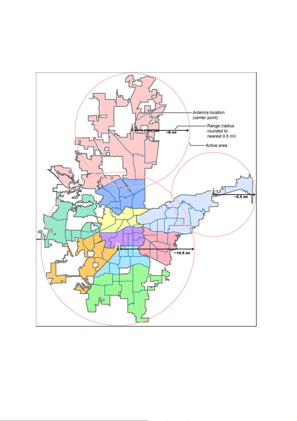
UBCD396XT
The Antenna-Centric Approach
Using an antenna-centric approach, you set the physical antenna location as the
system/sites center point and the antenna's actual reach as the range.
73
Page 88
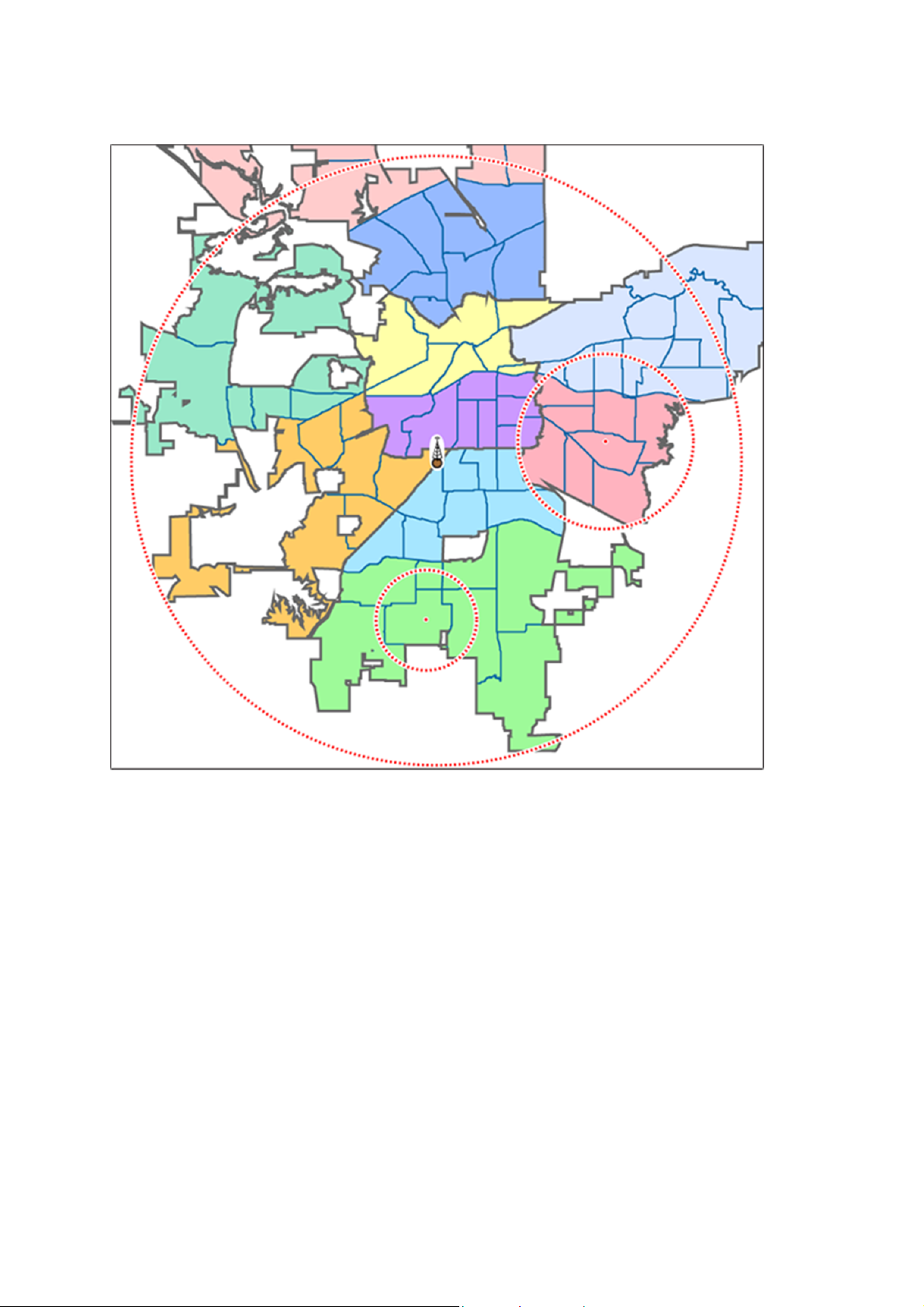
Combining for Efficiency
UBCD396XT
Because many trunked systems have both multiple antenna sites and multiple
agencies with differing geographic boundaries, you may want to combine the
approaches:
1. Use the antenna centric approach at the site level: set the geographic
coordinates of the antenna as the central location for each site.
2. Use the geopolitical approach at the channel group level. Within the same
system, set up a channel group for each agency, and set the central point of
the agency territory as the group location.
With both approaches combined into a single system, the scanner will now
seamlessly switch between antenna sites as needed to keep the scanner tuning only
to those sites you can receive well, and will also turn channel groups on and off as
you relocate to different jurisdictions.
74
Page 89

UBCD396XT
See Also
Section on Connecting a GPS receiver
Section on Programming locations
75
Page 90

UBCD396XT
20. Number Tags
Number Tags let you quickly navigate to a specific system or channel.
You can assign Number Tags at the system level (System Number Tag, or
SNT), at the channel level (Channel Number Tag , or CHNT), or at both
levels.
You can assign an SNT to the temporary system Close Call Hits that is
created during Close Call searches. This system and its SNT operate like any
other system.
You can assign Number Tags to service searches and custom search ranges.
These search Number Tags operate like regular SNTs.
Programming Number Tags
Assigning an SNT
SNTs can range from 0 to 999.
Systems can have the same SNT, but you will get a warning when you
create multiples. (This includes SNTs assigned to the Close Call Hits system
or any search ranges.)
To a system:
1. Open the Program System menu.
2. Select the system you want to assign the number tag to.
3. Select Edit Sys Option, then select Set Number Tag.
4. Enter the number tag you want to use for this system.
To the Close Call Hits system :
1. Open the Close Call menu.
2. Select Hits with Scan, then select Set Number Tag.
3. Enter the number tag you want to use for the Close Call Hits system.
To a service search range:
1. Open the Search for... menu.
2. Select Edit Service, then select the service search range you want to assign
the number tag to.
76
Page 91

UBCD396XT
3. Select Search with Scan, then select Set Number Tag.
4. Enter the number tag you want to use for this search range.
To a custom search range:
1. Open the Search for... menu.
2. Select Edit Custom, then select the custom search range you want to assign
the number tag to.
3. Select Search with Scan, then select Set Number Tag.
4. Enter the number tag you want to use for this custom search range.
Assigning a CHNT
You can assign CHNTs to channels even if the system does not have an
assigned SNT. However, without an SNT, you can only navigate to these
channels from within that system itself.
CHNTs can be duplicated within their own system, but you will see a
warning when you create multiples.
CHNTs can range from 0 to 999.
1. Open the Program System menu.
2. Select the system containing the channel you want to assign the number tag
to.
3. Select Edit Group, then select the channel group you want.
4. Select Edit Channel, then select the channel you want to assign the number
tag to.
5. Select Set Number Tag.
6. Enter the number tag you want to use for this channel.
77
Page 92

UBCD396XT
Using Number Tags
To navigate directly
to:
A system or search
range
A channel in the
current system
A channel in a
different system
Notes:
Key Sequence Example
1. Tap HOLD.
2. Enter the SNT + •.
3. Tap MENU.
If the SNT is 4, enter
HOLD / 4 / • / MENU.
1. Tap HOLD.
2. Enter the CHNT.
3. Tap MENU.
If the CHNT is 27, enter
HOLD / 27 / MENU.
1. Tap HOLD.
2. Enter the SNT
followed by the
decimal point.
If the SNT is 4 and the
CHNT is 27, enter HOLD
/ 4 / • / 27 / MENU.
3. Enter the CHNT.
4. Tap MENU.
If two systems have the same SNT, they will be selected in sequence (i.e. the
first time you select the SNT, the scanner will go to the first system assigned
with that SNT; if you select the same SNT again, it will go to the 2nd system
assigned with that SNT, and so on).
If two channels in the same system have the same CHNT, they will be
selected in sequence (i.e. the first time you select the CHNT, the scanner
will go to the first channel in that system assigned with that CHNT; if you
select the same CHNT again, it will go to the 2nd channel assigned with that
CHNT, and so on).
78
Page 93

UBCD396XT
21. Quick Keys
Quick Keys let you enable or disable systems and channel groups during a
scan. Disabled systems and channel groups are ignored during scans.
You can assign Quick Keys at the system/site level (System/site Quick Key
or SQK), at the channel group level (Group Quick Key, or GQK), or at both
levels.
You can assign an SQK to the temporary system Close Call Hits that is
created during Close Call searches. This system and its SQK operate like
any other system.
You can assign Quick Keys to service searches and custom search ranges.
These search Quick Keys operate like regular SQKs.
Programming Quick Keys
Assigning an SQK
Multiple systems, sites, and search ranges can share the same SQK.
All systems and sites assigned to the same SQK will be enabled (or
disabled) when you enter the Quick Key.
SQKs range from 0 to 99.
To a conventional system:
1. Open the Program System menu.
2. Select the system you want to assign the Quick Key to.
3. Select Edit Sys Option, then select Set Quick Key.
4. Enter the Quick Key you want to use for this system.
To a trunked system:
1. Open the Program System menu.
2. Select the system you want to assign the Quick Key to.
3. Select Edit Site, then select the site you want.
4. Select Set Quick Key, then enter the Quick Key you want to use for this site.
To the Close Call Hits system :
1. Open the Close Call menu.
2. Select Hits with Scan, then select Set Quick Key to.
3. Enter the Quick Key you want to use for the Close Call Hits system.
79
Page 94

UBCD396XT
To a service search range :
1. Open the Search for... menu.
2. Select Edit Service, then select the service search range you want to assign
the Quick Key to.
3. Select Search with Scan, then select Set Quick Key.
4. Enter the Quick Key you want to use for this search range.
To a custom search range :
1. Open the Search for... menu.
2. Select Edit Custom, then select the custom search range you want to assign
the Quick Key to.
3. Select Search with Scan, then select Set Quick Key.
4. Enter the Quick Key you want to use for this custom search range.
Assigning a GQK
All channels in the channel group will be enabled (or disabled) when you
enter the GQK.
Multiple channel groups in the same system can share the same GQK.
However, all of these channel groups will be enabled (or disabled) when you
enter the GQK from within that system.
You can assign GQKs to channel groups even if their system does not have
an assigned SQK.
You can only use GQKs within the current system: the GQK will not affect
a channel group in another system.
GQKs range from 0 to 9.
1. Open the Program System menu.
2. Select the system containing the channel group you want to assign the Quick
Key to.
3. Select Edit Group, then select the channel group you want.
4. Select Set Quick Key, then enter the Quick Key you want to use for this
channel group.
Using Quick Keys
Quick Keys only work in Scan mode.
80
Page 95

UBCD396XT
Entering the Quick Key toggles the enabled/disabled state of the
system/site/search range or channel group (i.e., if the system is currently
enabled, entering the Quick Key will disable it, and vice-versa).
To use SQK 0 through 9
Enter Scan mode.
Tap the number key that matches the SQK. (For example, if the SQK is 4,
just enter 4.)
Any systems, sites, or search ranges assigned to this SQK become disabled.
(If they were already disabled, they become enabled.)
To use SQK 10 through 99
Enter Scan mode.
Tap the decimal point ( ./NO ), then enter the SQK. (For example, if the
SQK is 32, enter ./NO / 32.)
Any systems, sites, or search ranges assigned to this SQK become disabled.
(If they were already disabled, they become enabled.)
To use a GQK
Enter Scan mode.
Go to the system that contains the channel group you want to enable or
disable.
Tap FUNCTION, then tap the number key that matches the GQK. (For
example, if the GQK is 7, enter FUNCTION / 7.)
Any channel groups assigned to this GQK within the current system only
become disabled. (If they were already disabled, they become enabled.)
81
Page 96

UBCD396XT
22. Search Keys
The scanner has three Search Keys that you can assign to a special search range;
the Search Keys are set to number keys 1, 2 , and 3:
Search Key 1 Search Key 2 Search Key 3
Programming Search Keys
1. Open the Search for... menu.
2. Select Set Search Key, then select the search key you want to program.
3. Select the search range you want to assign to this Search Key. Choose one of
the pre-programmed service search ranges, one of the 10 custom search
ranges, a Tone-Out search, or a Band Scope search.
Using Search Keys
To start the search assigned to a Search Key, FUNCTION + tap that Search Key.
For example, to start the search assigned to Search Key 2, FUNCTION + tap 2.
(You can't use the Search Keys when the scanner is in Scan mode or GPS mode.)
If the Search Key you select starts a Tone-Out search, the scanner switches to
Tone-Out mode and searches the most-recently-used Tone-Out channel (out of the
10 available). If you want to search a different Tone-Out channel, use the
SELECT-VOLUME-SQUELCH knob on handheld models to select the Tone-
Out channel you want to use.
82
Page 97

UBCD396XT
23. Programming locations
To use Location-based Scanning with a particular system, you will need to
program your scanner with the geographic coordinates you want to use for each
site or channel group. You can also program your scanner to alert you when you
approach particular locations.
Programming a location for a site
Each system site can have separate location information.
1. Open the Program System menu.
2. Select the system you want to program for location based scanning.
3. Select Edit Site, then select the first site you want to assign a location to.
4. Select the Set LocationInfo menu and enter the latitude, longitude, and range
for this site.
5. Change the Set GPS Enable field to On.
6. Go back to the Edit Site menu and repeat these steps with any other sites you
want to program for this system.
Programming a location for a channel group
Each channel group in a system can have separate location information.
1. Open the Program System menu.
2. Select the system you want to program for location based scanning.
3. Select Edit Group, then select the first channel group you want to assign a
location to.
4. Select the Set LocationInfo menu and enter the latitude, longitude, and range
for this site.
5. Change the Set GPS Enable field to On.
6. Go back to the Edit Group menu and repeat these steps with any other
groups you want to program for this system.
Remember: You have to turn on Set GPS Enable before the location
information can affect that site or channel group.
Programming general locations
You can program general locations (i.e., locations that are not associated with a
site or channel group). There are three types of general locations:
points of interest ( POI )
83
Page 98

UBCD396XT
intersections ( Dangerous Xing )
roads ( Dangerous Road )
You can program the scanner to alert you when you come within a designated
distance of that location.
To create a new location
1. Open the Program Location menu.
2. Select the type of location you want to create.
3. Select New Location to create a new location of this type.
4. If you want to create a different type of location, go back to the Program
Location menu and select that location type.
5. If you want to change the default location name, select Edit Name and enter
a new name.
6. Select Set LocationInfo and enter the latitude and longitude for this location.
7. Select Set Range and enter the distance from this location you want the
scanner to alert you.
8. Choose the Alert Tone and Alert Light you want the scanner to use when you
come within range of this location.
84
Page 99

UBCD396XT
For Dangerous Xing and Dangerous Roads only
In addition to range, you can specify a heading and a speed limit for these types of
locations:
If you set a speed limit, the scanner will only trigger an alert when you are
within the location's range and your current speed is over the programmed
speed limit.
If you set a heading, the scanner will only trigger an alert when you are
within the location's range and your current heading is +/- 45 degrees from
the programmed heading. (For example, if you set the heading as North , the
scanner will trigger an alert if your current heading is North-east but not if
your current heading is due East.)
Edit an existing location
1. Open the Program Location menu.
2. Select the type of location you want to edit; the scanner lists the existing
locations of that type in alphabetical order.
3. Select the location you want to edit, then change any of the location settings
you want.
85
Page 100

UBCD396XT
24. Setting alerts
Your scanner can trigger alerts for several different events. The table below shows
the different alerts and how to program them:
To sound an alert when Follow these steps
A channel becomes active Edit the channel properties (Edit
Channel#Set Alert):
1. Go to the Program System menu and select
the system that contains the channel you
want set the alert for.
2. Select Edit Group, then select the group you
want.
3. Select Edit Channel, then select the channel
you want to set the alert for.
4. Select Set Alert.
5. Choose the Alert Tone and Alert
1. Light you want the scanner to use.
An active Talk Group on a
system contains an emergency
flag
The scanner detects a Close
Call hit
The scanner gets a hit on a
Tone-Out
channel
Edit the system properties (Edit Sys
Option#Emergency Alert):
1. Go to the Program System menu and select
the system you want set the alert for.
2. Select Edit Sys Option, then select
2. Emergency Alert.
3. Choose the Alert Tone and Alert
4. Light you want the scanner to use.
Edit the Close Call properties:
1. Go to the Close Call menu.
2. Select Set CC Alert .
3. Choose the Alert Tone and Alert
Light you want the scanner to use.
4. For Close Call Alerts, you can also have the
scanner pause before it resumes searching.
Select Set CC Pause to activate this feature.
Edit the Tone-Out channel properties:
1. Go to the Tone-Out for... menu.
2. Select Tone-Out Setup, then select the
86
 Loading...