

Page 1

CONTENTS
Introduction......................................1
Welcome......................................1
Features.......................................1
IncludedInYourPackage.........................2
SettingUpAndAdjustingYourPhone..................3
Selecting The Location ...........................3
Connecting The Telephone Line ....................3
Connecting The Telephone Cords ...................4
PowerToTheBase&ChargerUnits.................5
WallInstallation................................6
AttachingTheBeltClip...........................9
InstallingTheBattery...........................10
ChargingTheBattery...........................10
ChargingSecondBattery.........................11
LowBatteryIndicator...........................11
CleaningBattery&ChargingUnitContacts..........12
HandsetUse.....................................13
ANA9620 Handset Controls.......................13
UsingTheHandset .............................14
AnsweringACall...............................15
MakingACall.................................15
CONTENTS
ProgrammingFunctions...........................16
PBXOrPSTN..................................16
ProgramModeSetup............................16
ProgrammingXFERInPBX ......................17
ProgrammingCONFInPBX......................18
UsingTheFeatureButtons.......................19
PBXFeatures..................................19
PSTNFeatures.................................22
Accessories......................................24
OptionalHeadSet..............................24
OptionalBackupAdapter........................24
OtherAccessories&Parts........................25
Troubleshooting..................................26
Specifications....................................27
Uniden®is a registeredtradema rkof Uniden America Corporat ion.
Page 2
Introduction
WELCOME
INTRODUCTION
TO YOUR NEW PHONE
Congratulations on your purchase of the Uniden
Cordless Telephone. The
engineered to exacting standards for reliability, long life, and
outstanding performance. To get the most from your
ANA9620
familiarize you with the features of your cordless phone,
refer to the handset and base illustration foldout from the
rear cover.
FEATURES
Super Long Range 900 MHz Digital
•
2-line, 16-digit LCD Display
•
PBX or PSTN Operating Mode
•
Single button access to: CONFERENCE, HOLD, TRANSFER,
•
PAUSE, FLASH/REDIAL, and MUTE features
•
Redial Capability up to the last 3 numbers dialed
•
AutoStandby
•
Any Key Answer
•
AutoTalk
•
Auto Line Select
•
Silent Alert
•
Ringer and Handset Volume Controls
•
Four Ringer Tones
•
Out of Range Protection
•
Low Battery Protection System
, please read this Owners Manual thoroughly. To
ANA9620
is designed and
ANA9620
INTRODUCTION
PSTN or PBX
The
ANA9620
line (PSTN) or an analog PBX port (PBX).
is designed to work on a standard telephone
1
Page 3
TIP
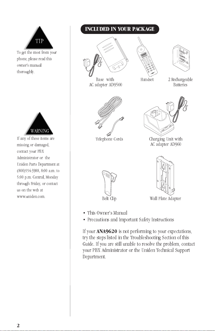
INCLUDED IN YOUR PACKAGE
To get the most from your
phone, please read this
owners manual
thoroughly.
WARNING
If any of these items are
missing or damaged,
contact your PBX
Administrator or the
Uniden Parts Department at
(800)554-3988, 8:00 a.m. to
5:00 p.m. Central, Monday
through Friday, or contact
us on the web at
www.uniden.com.
msg
lock
vol
batlow
talk
chan
talk
F4
mute
F3
hold
F2
conf
F1
xfer
def
3
abc
mno
6
12
jkl
5
wxyz
9
ghi
4
tuv
8
#
pqrs
7
oper
0
Base with
Handset 2 Rechargeable
AC adapter AD9500
Telephone Cords Charging Unit with
AC adapter AD960
Belt Clip Wall Plate Adapter
Batteries
•
This Owners Manual
•
Precautions and Important Safety Instructions
If your
ANA9620
is not performing to your expectations,
try the steps listed in the Troubleshooting Section of this
Guide. If you are still unable to resolve the problem, contact
yourPBXAdministratorortheUnidenTechnicalSupport
Department.
2
Page 4
SettingUp and AdjustingYourPhone
TIP
Before choosing a location
foryourphone,readthe
Installation
Considerations included in
the Precautions and
Important Safety
Instructions brochure.
SELECTING THE LOCATION
Select a location for the
humidity. The base of your
desk or tabletop near a standard 120V AC outlet and
telephone line jack. The base can also be mounted on a
standard
mount adapter. Keep the base and handset away from
sources of electrical noise (motors, fluorescent lighting,
computers).
CONNECTING THE TELEPHONE LINE
There are three types of phone outlets:
▼
Plug the telephone line cord from the base into a standard
modular telephone jack(s). (
modular jack, contact your local telephone company for
information on the installation of these jacks.)
▼
AT&T or GTE wall plate usin g the included wall
1) Modular Jack
2) 4-Prong Jack
ANA9620
ANA9620
Note
to avoid excessive heat or
can be placed on a
:Ifyoudonothavea
SETTING UP
AND ADJUSTING YOUR PHONE
SETTING UP
An adapter (not included) is required. The adapter plugs into
the 4-prong jack and the telephone line cord plugs into the
adapter.
▼
3) Hard-wired Jack
A modular j ack converter (not included) is required. You
may need to rewire when con necting the converter (making
color-coded connections).
Your Uniden telephone dealer or a telephone supply
store can advise you on the proper adapter or converter.
3
Page 5
TIP
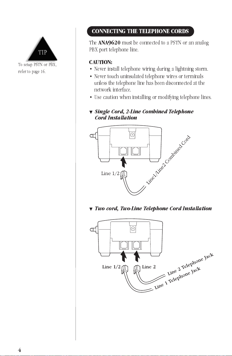
CONNECTING THE TELEPHONE CORDS
The
ANA9620
PBX port telephone line.
must be connected to a PSTN or an analog
To setup PSTN or PBX,
refer to page 16.
CAUTION:
Never install telephone wiring during a lightnin g storm.
•
Never touch uninsulated telephone wires or terminals
•
unless the telephone line has been disconnected at the
network interface.
Use caution when in s talling or modifying telephone lines.
•
Single Cord, 2-Line Combined Telephone
▼
Cord Installation
▼
Two cord, Two-Line Telephone Cord Installation
4
Page 6
!
Use only the Uniden
AC adapter AD9500
supplied with this base.
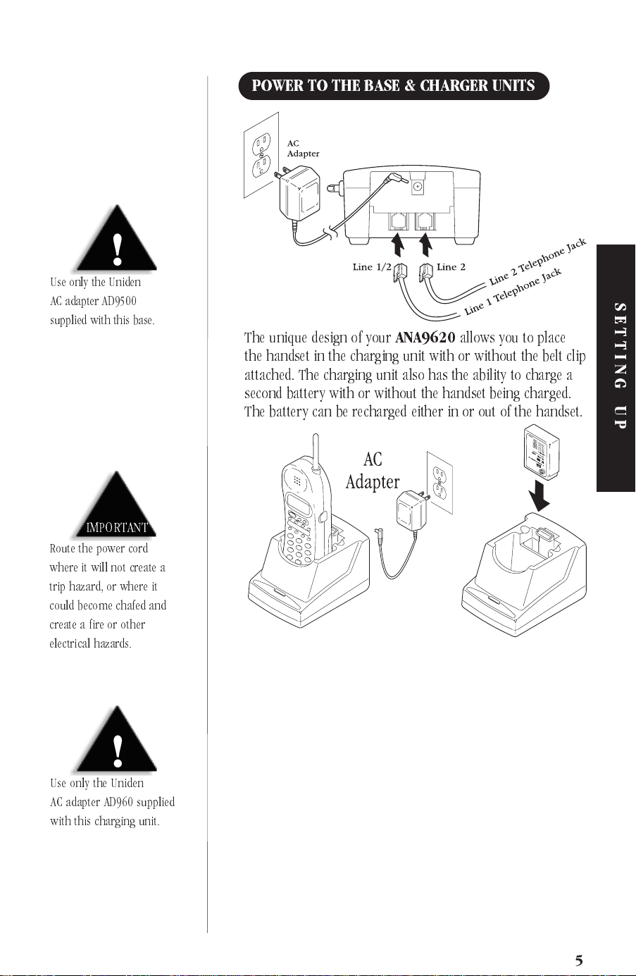
POWER TO THE BASE & CHARGER UNITS
Theuniquedesignofyour
the handset in the charging unit with or without the belt clip
attached. The charging unit also has the ability to charge a
second battery with or without the handset being charged.
The battery can be recharged either in or out of the handset.
ANA9620
allows you to place
SETTING UP
IMPORTANT
Route the power cord
where it will not create a
trip hazard, or where it
could become chafed and
create a fire or other
electrical hazards.
!
Use only the Uniden
AC adapter AD960 supplied
with this charging unit.
5
Page 7
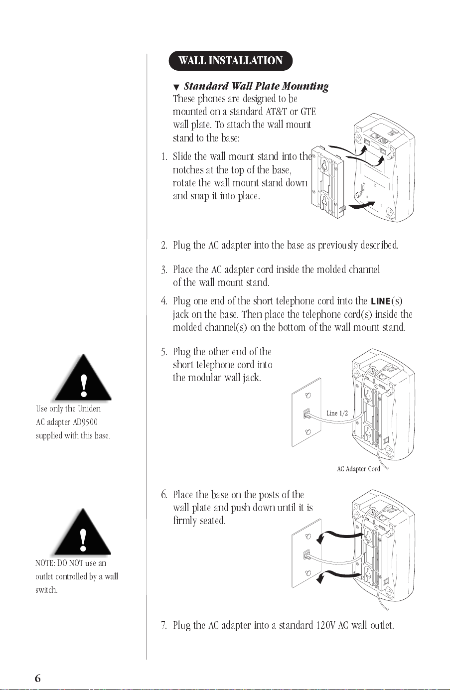
WALL INSTALLATION
Standard Wall Plate Mounting
▼
These phones are designed to be
mounted on a standard AT&T or GTE
wall plate. To attach the wall mount
stand to the base:
1. Slide the wall mount stand into the
notches at the top of the base,
rotate the wall mount stand down
and snap it into place.
2. Plug the AC adapter into the base as previously described.
3. Place the AC adapter cord inside the molded channel
of the wall mount stand.
4. Plug one end of the short telephone cord into the
jack on the base. Then place the telephone cord(s) inside the
molded channel(s) on the bottom of the wall mount stand.
LINE
(s)
!
Use only the Uniden
AC adapter AD9500
supplied with this base.
!
NOTE:DONOTusean
outlet controlled by a wall
switch.
5. Plug the other end of the
short telephone cord into
the modular wall jack.
6. Place the base on the posts of the
wall plate and push down until it is
firmly seated.
7. Plug the AC adapter into a standard 120V AC wall outlet.
6
Page 8
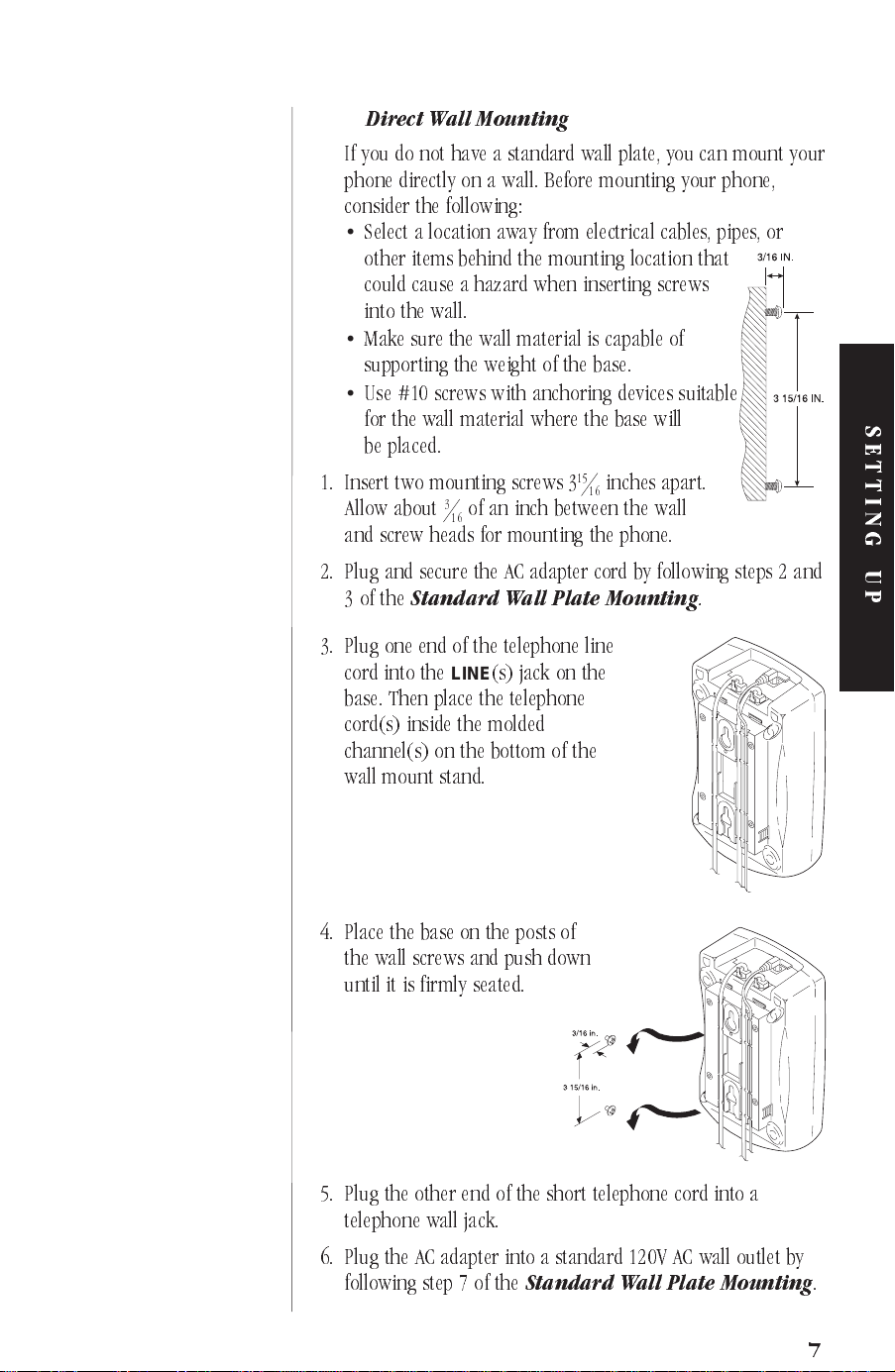
Direct Wall Mounting
▼
If you do not have a standard wall plate, you can mount your
phone directly on a wall. Before mounting your phone,
consider the following:
Select a location away from electrical cables, pipes, or
•
other items behind the mounting location that
could cause a hazard when inserting screws
into the wall.
Make sure the wall material is capable of
•
supporting the weight of the base.
Use #10 screws with anchoring devices suitable
•
for the wall material where the base will
be placed.
1. Insert two mounting screws 3
Allow about
3
of an inch between the wall
16
15
inches apart.
16
and screw heads for mounting the phone.
2. Plug and secure the AC adapter cord by following steps 2 and
3ofthe
Standard Wall Plate Mounting
.
3. Plug one end of the telephone line
cord into the
LINE
(s) jack on the
base. Then place the telephone
cord(s) inside the molded
channel(s) on the bottom of the
wall mount stand.
SETTING UP
4. Place the base on the posts of
thewallscrewsandpushdown
untilitisfirmlyseated.
5. Plug the other end of the short telephone cord into a
telephone wall jack.
6. Plug the AC adapter into a standard 120V AC wall outlet by
following step 7 of the
Standard Wall Plate Mounting
.
7
Page 9
!
Use only the Uniden
AC adapter AD9500
supplied with this base.
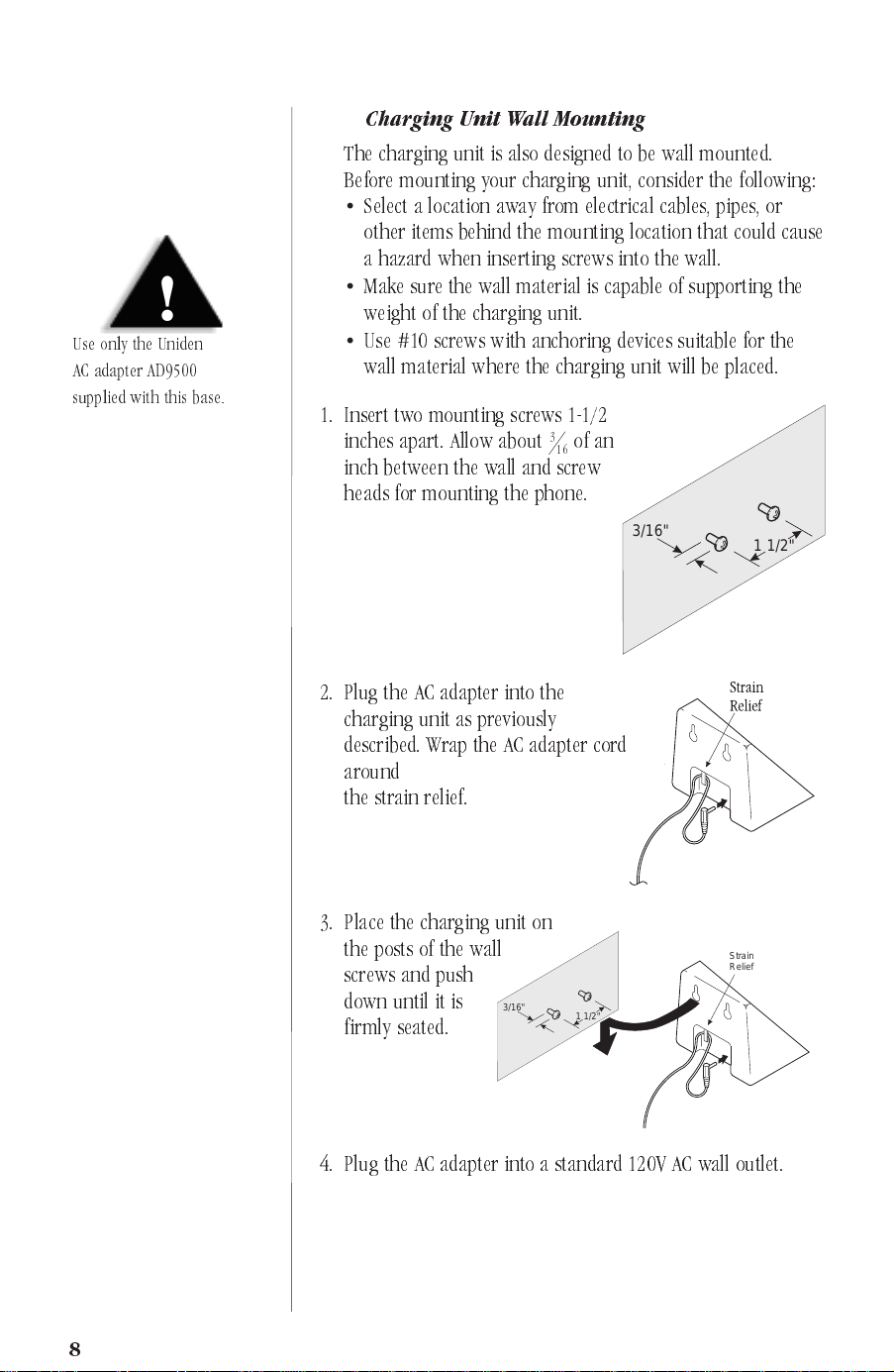
Charging Unit Wall Mounting
▼
The charging unit is also designed to be wall mounted.
Before mounting your charging unit, consider the following:
Select a location away from electrical cables, pipes, or
•
other items behind the mounting location that could cause
a hazard when inserting screws into the wall.
Make sure the wall material is capable of supporting the
•
weight of the charging unit.
Use #10 screws with anchoring devices suitable for the
•
wall material where the charging unit will be placed.
1. Insert two mounting screws 1-1/2
inches apart. Allow about
3
16
of an
inch between the wall and screw
heads for mounting the phone.
2. Plug the AC adapter into the
charging unit as previously
described. Wrap the AC adapter cord
around
the strain relief.
3. Place the charging unit on
the posts of the wall
screws and push
down until it is
3/16"
firmly seated.
1 1/2"
3/16"
Strain
Relief
1 1/2"
4. Plug the AC adapter into a standard 120V AC wall outlet.
8
Page 10
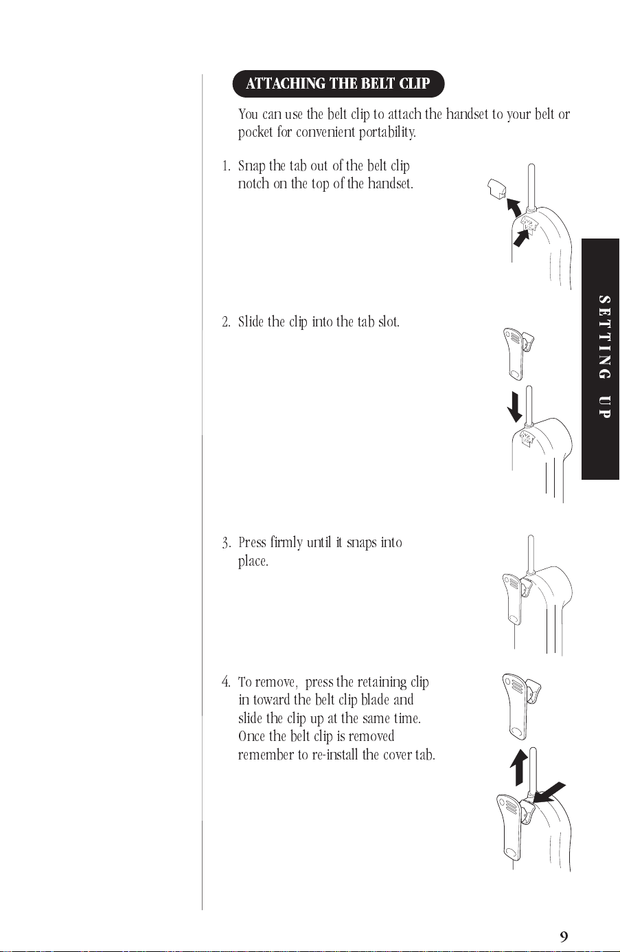
ATTACHING THE BELT CLIP
You can use the belt clip to attach the handset to your belt or
pocket for convenient portability.
1. Snap the tab out of the belt clip
notch on the top of the handset.
2. Slide the clip into the tab slot.
SETTING UP
3. Press firmly until it snaps into
place.
4. To remove, press the retaining clip
in toward the belt clip blade and
slide the clip up at the same time.
Once the belt clip is removed
remember to re-install the cover tab.
9
Page 11

INSTALLING THE BATTERY
1. Remove the battery
cover by pressing
the latch and
sliding the cover
down and off of
the handset.
!
Use only the sealed
lead-acid battery
(part # BT9000) supplied
with this phone.
NOTE
Charge the battery without
interruption for 5 hours.
2. Slide the battery
down into the
NOTCH
handset.
Note: The
system which allows the battery to be replaced while in
operation, as long as it is replaced within 20 seconds.
ANA9620
has a low battery protection
3. Place the cover
and slide the cover
up until it latches
into the handset.
CHARGING THE BATTERY
The rechargeable sealed lead-acid battery must be fully
charged before using your
1. Place the handset in the front slot of the charging unit.
ANA9620
for the first time.
NOTE
TheCharge1indicator
light does not go off,
even when the charge
is complete.
10
2. Make sure the
lights. If the
CHARGE 1
CHARGE 1
indicator
indicator
doesnt light, check to see that the
AC adapter is plugged in, and that
the handset is making good contact
with the charging unit . Two charge
pockets are available on the
ANA9620, with separate indicator
lights for each. The handset battery
and the second battery may be
charged simultaneously.
Page 12

CHARGING SECOND BATTERY
IMPORTANT
You can leave the second
battery in the second slot. It
will not overcharge.
NOTE
Charge the battery without
interruption for 5 hours.
The charger unit of your
ANA9620
is equipped to charge
the second battery with or without the handset in the front
slot.
1. Slide the second battery into the second
slot in the charging unit until the retaining clip
snaps over the top of the battery.
2. Make sure the
lights. If the
CHARGE 2
CHARGE 2
indicator
indicator
doesnt light, check to see that the
AC adapter is plugged in, and that
the battery is making good contact
with the charging unit.
3. When charging is complete, the
CHARGE 2
indicator goes
off. Press the latch to remove the battery. If you dont need
the battery immediately, leave it in the charging
compartment; it will not overcharge. If you place a fully
charged battery in the
CHARGE 2
slot, the
CHARGE 2
lights briefly when you insert the battery.
4. You can replace the
ANA9620
battery during a call. You
have up to 20 seconds to replace the battery.
SETTING UP
LED
LOW BATTERY INDICATOR
When the handset battery is low
and needs to be charged, you will
see the
batt low
On A Call In Standby Mode
Only the
Handset beeps once every 3
seconds.
Complete your call as quickly
as possible
Replace battery within
20 seconds to continue call.
talk
Return the handset to the charging unit for charging or
replace the handset battery with another charged battery .
icon in the display.
button operates.
batt low
None of the buttons operate.
Handset beeps every 15 seconds
Cannot make call.
Replace battery before making
a call.
11
Page 13

NOTE
Do not clean the charging
unit without first checking
to ensure that it has
been unplugged.
CLEANING BATTERY & CHARGING UNIT CONTACTS
To maintain a good charge, it is
important to clean all charging
contacts on the handset, second
battery and charging unit about
once a month. Use a pencil eraser
or other contact cleaner.
Do not use any liquids or solvents.
12
Page 14

HandsetUse
FOR YOUR NEW PHONE
Before using your
ANA9620
,besuretoraisetheantennato
the vertical position.
Note: Operation of the
handset out of the charging unit.
ANA9620
is performed using the
ANA9620 HANDSET CONTROLS
talk
Condition Ac t i o n LCDDisplay
Handset
Earpiece Volume
(talk mode)
Ringer select
(standby mode)
Press
vol
on the front of the
handset to select a high or
low earpiece volume level.
Press
vol
on the front of the
handset to select one of the
following settings:
chan
vol
No display
indications.
HANDSET USE
HANDSET USE
Ring type A (High)
Ring type A (Low)
Ring Type B (High)
Ring Type B (Low)
Ring Off (Silent Alert)
Ring Type A
Ring Type A
High
High
Ring Type A
Ring Type A
Low
Low
Ring Type B
Ring Type B
High
High
Ring Type B
Ring Type B
Low
Low
Ring Off
13
Page 15

USING THE HANDSET
When you pick up the handset and
press
talk
, you will see:
After the connection has been made
between the handset and base, the
displaywillshowthelines
currently connected:
Or, you may see one of the following:
Condition Indicator LCD Screen
AQUIRING
LI N K
no connection to base error tone
channel busy error tone no display indication.
line in use l1 or l2
indicator
blinks.
If the handset is at the range limit
of the
ANA9620
,ornopoweris
no service
l1 line in use
or
l2 line in use
NO SERVICE
going to the base, you may see:
Take the following action:
During a Call In Standby Mode
Sound is Muted Cant make or answer calls
Condition
Actio n
Move back in range
within 20 seconds or
check power to the
base.
(Phone may ring
intermittently)
Move back within range or
check power to the base.
14
Page 16

ANSWERING A CALL
When you receive a call, the
handset rings and you will see:
Handset in the Charging Unit Handset out of Charging Unit
Pick up the handset. The
AutoTalk
answer the call immediately.
When you finish the call, place the handset back in the charging
unit. AutoStandby automatically hangs up the phone.
OR
Press
feature allows you to
talk
to hang up the phone.
Press
talk
.
Or p ress any key on the
numerickeypad,or
PAUSEorFLASH/RDL
HOLD
,
MAKING A CALL
Press talk.
The
ANA9620
busy, the phone automatically selects an available line.
OR
Press L1 or L2.
When you hear a dial tone, enter the number you are calling.
To hang up, press
selects the last line used. If one line is
5551212
talk
talk
.
HANDSET USE
REDIAL FUNCTION
The
ANA9620
you dialed. To redial these numbers:
1. Press
FLASH/RDL
The last number dialed appears in
the display.
To scroll through the remaining
two numbers, press
2. When the desired number appears,
talk,L1orL2
press
stores up to the last three phone numbers
FLASH/RDL
to redial.
again.
15
Page 17

ProgrammingFunctions
PBX OR PSTN
In the Programming mode, you can select either Analog PBX or
PSTN (Public Service Telephone Network) operation. The default
is PSTN.
FUNCTIONS
Available features of each mode of operation are illustrated in the
table below.
Feature Analog PBX PSTN
Conference Conference by PBX Connect Lines 1 & 2
Transfer Transfer by PBX Not Available
Note: Both Conference and Transfer commands must be
programmed to their respective keys before these
features can be used.
PROGRAM MODE SETUP
To enter the Program mode, perform the following steps:
1. At
Standby,press and hold the
#
, keys. While holding the
#
and keys, press and hold
the
talk
key until a short beep is
heard and the handset LCD displays:
2. Press the
PBX modes.
3. Press the
into memory. The handset LCD displays:
The phone returns to
For operation in
PBX mode
chanorvol
talk
key to enter your selection
, see page 17.
keys to switch between and PSTN Analog
Standby
PSTN mode
.
, see page 19. For operation in
PROGRAMMING
16
Page 18

PROGRAMMING XFER IN PBX
Note: Before programming these commands, contact
your PBX Administrator to obtain programming codes.
The
XFER
key can be programmed for special use, such as
causing a Hook Flash followed by a special number or
function.
The Hook Flash is used to send a signal to the PBX system to
initiate a transfer.
XFER
For example to program the
and the9key for outside transfers only:
key for Hook Flash
Press and hold
seconds.
The talk icon blinks
FLASH/RDL
Press
9
.
Press
XFER
XFER
.
.
Press
Press
PAUSE
.
for two
PROGRAMMING PBX
For the
ANA9620
,thetransferkeyisoperatedbythe
Hook-Flash function. Program your system transfer code with
the assistance of the PBX System Administrator.
17
Page 19

NOTE
Theconferencekeycanbe
programmed for special use,
such as causing a Hook
Flash followed by a special
number or function.
PROGRAMMING CONF IN PBX
Your PBX systems configuration determines how the
conference feature works. Con tact your PBX admin istrator
for exact operation details. The example below is just a
representation.
CONF
For example to program the
Press and hold
seconds. The
PAUSE
talk
icon blinks.
for two
key for Hook Flash :
Press
Press
Press
Press
For the
FLASH/RDL
9
.
CONF
CONF
ANA9620
.
.
.
, the conference key is operated by the
Hook-Flash function. Program your system conference code
with the assistance of the PBX System Administrator.
18
Page 20

NOTE
The exact operation of the
Feature Buttons depends
on how your PBX system is
configured. Contact your
PBX Administrator for
more information.
USING THE FEATURE BUTTONS
Placing a Call on Hold
▼
HOLD
Press
and see:
To resume the call, press
Transferring A Call
▼
XFER
The
Refer to the PROGRAMMING XFER IN PBX
section.Press
you will hear a beep,
and you will see:
. You will hear a beep
L1orL2ortalk
keymustbeprogrammedbeforeuse.
XFER
(TRANSFER),
PBX FEATURES
.
Dial the target number.
talk
When the receiving party answers, press
the transfer.
Note:The transfer feature is not available in PSTN mode
▼
Connecting a PBX Conference Call
Refer to the PROGRAMMING CONF IN PBX section.
1. To connect a second party to a call in progress,
CONF
CONF
(CONFERENCE).
to have a three-way conversation.
press
You willl hear a beep, and see:
2. Dial the second partys number.
3. When the other party answers,
press
XFER
3410
to complete
.
FEATURES
Note:In PBX mode, multiline conferencing is available
according to the config uration of the PBX system.
.
19
Page 21

PBX Features
L1
Key
▼
L1
Press the
L2
▼
Press theL2key to initiate a call on Line 2.
CONF
▼
keytoinitiateacallonLine1.
Key
In PBX mode, the
CONF
key must f irst be programmed.
Refer to the s ection entitled PROGRAMMING CONF IN PBX.
XFER
▼
Press
XFER
(TRANS FER), you will hear a beep.
Dial the target number.
When the receiving party answers, press
XFER
to
complete call.
Note
: This feature is only available in PBX mode.
▼
HOLD
Press once, you will hear a beep and the call is placed
on hold.
L1, L2ortalk
Press
▼
PAUSE
In PBX mode, the
and
XFER
feature buttons. Refer to the sections entitled
to resume the call.
PAUSE
key is used to program the
CONF
PROGRAMMING XFER IN PBX and PROGRAMMING
CONF IN PBX.
20
▼
FLASH/RDL
Press once to cause a Hook Flash while on a call.
In
Standby
mode, you can redial any one of the last three
numbers previously dialed.
Page 22

▼
MUTE
ThiskeyturnsthehandsetMIConoroffwhilein
talk
mode.
It toggles between on and off.
vol
KEY
▼
This key selects the ringer volume level or tone (or silent
alert) during
Standby
, and handset earpiece audio level
during a call. The same key also selects the item during
programming mode.
chan
▼
The
KEY
ANA9620
automatically selects the clearest of three
channels during a call for maximum audio quality. But, if
chan
you hear static or noise during a call, press
to select a
clear channel.
PBX FEATURES
21
Page 23

PSTN Features
L1
Key
▼
L1
Press the
L2
▼
Press theL2key to initiate a call on Line 2.
CONF
▼
To connect a second party to a call in progress:
1. Press
call on hold.
2. Press L2.
keytoinitiateacallonLine1.
Key
HOLD
, to place the current
22
3. Dial the other persons number.
4. When the other party answers, press
CONF
to have
a three-way conversation.
CONFERENCE
talk
▼
XFER
Note:
This feature is not available in PSTN mode.
▼
HOLD
Press once, you will hear a beep and the call is placed
on hold.
Press
L1, L2ortalk
to resume the call.
Page 24

PAUSE
▼
Press once to cause a four second pause while dialing
anumber.
FLASH/RDL
▼
Press once to cause a Hook Flash while on a call.
In
Standby
mode, you can redial any one of the last three
numbers previously dialed.
MUTE
▼
ThiskeyturnsthehandsetMIConoroffwhilein
talk
mode.
It toggles between on and off.
vol
Key
▼
This key selects the ringer volume level or tone (or silent
alert) during
Standby
, and handset earpiece audio level
during a call. The same key also selects the item during
programming mode.
▼
chan
Key
The
ANA9620
automatically selects the clearest of three
channels during a call for maximum audio quality. But, if
chan
you hear static or noise during a call, press
to select a
clear channel.
PSTN FEATURES
23
Page 25

FOR YOUR NEW PHONE
Accessories
OPTIONAL HEAD SET
The optional headset (EXP9530) provides a Hands-Free
Option for the
can use the belt clip to carry the handset, and conduct a
conversation using the headset.
To install the optional
headset, open the cover
over the headset jack
and plug the headset in.
No other settings
are needed.
ANA9620
. With the headset installed, you
Operation of the
same as using the handset. However, you will hear through
the head set earphone, and talk through the headset
microphone. The handset earphone and microphone
(mouthpiece) are disconnected.
OPTIONAL BACKUP ADAPTER
The optional backup adapter (EXP9505) provides protection
against losing a call in case of AC power failure. The backup
adapter contains a battery that provides enough power for
you to complete the call and hang up.
▼
To install the backup adapter:
1. Disconnect the standard AC adapter from the
2. Plug the backup adapter into the EXP9505 j ack.
3. Plug the wire from the EXP9505 into the
ANA9620
using the headset is exactly the
ANA9620
DC IN
jack of the base.
To Base Unit
base
.
24
ACCESSORIES
From AC
Adapter
Backup
AC Adapter
Page 26

OTHER ACCESSORIES & PARTS
For the following optional accessories and replacement parts
contact your PBX Administrator.
AC Adapter Part # AD9500
for the Base
Backup Adapter
EXP9505
Head Set
EXP9530
Charger and AC Adapter
500 mAh Battery
BT-9000
Telephone Cord
EXP9685
Leather Case
EXP9683
BaseWall Mount
EXP9660
Belt Clip
EXP9602
•
Operating Guide - OMANA9620
Belt Clip
EXP9603
ACCESSORIES
25
Page 27

Troubleshooting
If your
ANA9620
your expectations, try these steps. If you are still unable to
resolve the problems, contact your PBX Administrator or the
Uniden Technical Support Department.
Note:
Do not attempt to service this unit yourself. All
servicemustbedonebyqualifiedservicepersonnel.
Cordless Telephone is n ot performing to
FORYOURPHONE
Problem Suggestion
Charge light wont
come on when
handset is placed in
charging unit.
Conversation
interrupted
frequently.
Warning tone and
NO SERVICE
message.
Handset doesnt ring.
•
Make sure the AC adapter is plugged into
the base and wall outlet.
•
Make sure handset is properly seated in
charging unit.
•
Make sure the sealed lead-acid battery is
properly placed in the handset.
•
Make sure that the charging contacts on
the handset and charging unit are clean.
•
Make sure that the base antenna is fully
vertical.
•
Move closer to the base.
•
Check for
•
Move closer to the base.
•
Sealed lead-acid battery may be weak.
Charge the battery for 5-6 hours.
•
Make sure the base antenna is fully
vertical.
•
Thehandsetmaybetoofarawayfrom
the base.
•
Ensure the ringer ON/OFF switch is in
the ON position.
LOW BATT
warning.
26
TROUBLESHOOTING
Page 28

FORYOURPHONE
Specifications
GENERAL
The
ANA9620
Frequency Control :Phase Lock Loop
Modulation :FM
Operating Temperature :−10° to 50° C
BASE
Receive/Transmit Frequency :902 MHz to 928 MHz
Power Requirements :10V DC from supplied AC adapter
Size :41/4in.Wx71/2in.Dx21/4in.H
Weight :Approx. 15.4 oz.
complies with FCC parts 15 and 68, and IC standards.
SPECIFICATIONS
HANDSET
Receive/Transmit Frequency :902 MHz to 928 MHz
Power Requirements :Rechargeable sealed lead acid
battery
Size :21/4in.Wx11/2in.Dx81/2in.H
with antenna
Weight :Approx. 8.8 oz. with battery
Battery :Capacity 500 mAH, 4.0V
Talk Mode :5 hours (typical)
Standby Mode :40 hours (typical)
Specifications shown are typical and subject to change without notice.
SPECIFICATIONS
27
Page 29

Covered under one or more of the following U.S. patents:
4,511,761, 4,523,058, 4,595,795, 4,597,104, 4,797,91 6,
4,803,491, 5,157,686, 5,253,268 and other patents pending
UNYL3203000 ©1998 Uniden America Corporation.
Printed in the China All rights reserved.
2
Page 30

HANDSET C ONTROLS & FU NCTIONS
1. Ringer ON/OFF switch 9. Microphone
2. Message Display 10.Headset Jack
3. Talk(
4.
talk
)Key
L2
Key 12.Volume (
11. Channel(
chan
vol
5.L1Key 13.Conference (
6. Hold (
HOLD
)Key 14. Transfer (
XFER
(PBX mode only)
7. Pause (
)Key 15.Mute(
MUTE
PAUSE
8. Numeric Keypad 16. Flash/Redial (
)Key
)Key
CONF
)Key
)Key
)Key
FLASH/RDL
)Key
Page 31

BASE CONTROLS & FU NCTION S
Page 32

●
Printed in China
●
`
 Loading...