


Contents |
|
The FCC Wants You To Know ................................................................................................................... |
1 |
Scanning Legally ........................................................................................................................................ |
2 |
Introduction ................................................................................................................................................. |
3 |
Using this Manual ................................................................................................................................... |
5 |
Understanding Scanning ............................................................................................................................ |
6 |
Conventional Scanning ........................................................................................................................... |
6 |
Simplex Operation .............................................................................................................................. |
6 |
Repeater Operation ............................................................................................................................ |
6 |
Trunked Scanning .................................................................................................................................. |
7 |
Motorola Trunking ............................................................................................................................... |
7 |
EDACS Trunking ................................................................................................................................ |
8 |
LTR Trunking ...................................................................................................................................... |
9 |
Understanding Banks and Channels ...................................................................................................... |
9 |
Getting More Information ......................................................................................................................... |
10 |
Front and Rear View ................................................................................................................................ |
11 |
Display Icons ........................................................................................................................................ |
12 |
Included With Your Scanner .................................................................................................................... |
13 |
Setting Up Your Scanner ......................................................................................................................... |
14 |
Connecting an Antenna ........................................................................................................................ |
14 |
Mounting an Antenna ........................................................................................................................... |
14 |
Optional Antenna .................................................................................................................................. |
14 |
Typical Mounting Methods ................................................................................................................... |
15 |
Mounting the Scanner in Your Vehicle ................................................................................................. |
15 |
Applying Power for Vehicle Installation ................................................................................................ |
16 |
Desktop Installation .............................................................................................................................. |
17 |
Applying Power Using Standard AC Power ......................................................................................... |
17 |
Connecting an External Speaker .......................................................................................................... |
17 |
Connecting an Earphone ...................................................................................................................... |
17 |
Listening Safely .................................................................................................................................... |
18 |
Connecting the Clone Cable ................................................................................................................ |
18 |
Connecting the Tape Recorder ............................................................................................................ |
18 |
Basic Operation ........................................................................................................................................ |
19 |
Turning On the Scanner ....................................................................................................................... |
19 |
Setting the Squelch .............................................................................................................................. |
19 |
Using the Menu .................................................................................................................................... |
20 |
Manually Selecting a Channel .............................................................................................................. |
20 |
Scanning Programmed Channels ........................................................................................................ |
20 |
Locking/Unlocking Banks ..................................................................................................................... |
20 |
Locking/Unlocking Channels ................................................................................................................ |
21 |
Restoring All Locked Out Channels ..................................................................................................... |
21 |
Priority Scanning .................................................................................................................................. |
21 |
Priority Plus Scanning .......................................................................................................................... |
21 |
Listening to the Input Channel ............................................................................................................. |
21 |
Dimmer Light Setting ............................................................................................................................ |
22 |
Controlling How Much Information Appears ......................................................................................... |
22 |
Turning the Key Beep On/Off ............................................................................................................... |
22 |
Locking the ENTER key ....................................................................................................................... |
22 |
Disabling the APCO25 Card ................................................................................................................. |
23 |
Muting All Audio ................................................................................................................................... |
23 |
Setting Squelch Mode .......................................................................................................................... |
23 |
Trunk Scanning Options ....................................................................................................................... |
23 |
Searching for Active Talkgroups (ID Search) ................................................................................... |
23 |
Scanning Only Stored Talkgroups (ID Scan) ................................................................................... |
24 |
Monitoring Talkgroup ID’s ................................................................................................................. |
24 |
Selecting Talkgroup Lists to Scan .................................................................................................... |
24 |
Holding on a Single Talkgroup ......................................................................................................... |
24 |
Locking Out Talkgroups .................................................................................................................... |
24 |
EDACS Blockout ............................................................................................................................... |
25 |
Unlocking All Talkgroups .................................................................................................................. |
25 |
EDACS Patch Tracking .................................................................................................................... |
25 |
Searching ................................................................................................................................................. |
26 |
Holding on an Active Frequency .......................................................................................................... |
26 |
Setting Chain Search ........................................................................................................................... |
26 |
Setting Data Skip .................................................................................................................................. |
26 |
Skipping Frequencies ........................................................................................................................... |
26 |
Storing Found Frequencies .................................................................................................................. |
27 |
Automatically Storing Frequencies ....................................................................................................... |
27 |
Setting Subaudible Tones for Searching .............................................................................................. |
28 |
Searching for Subaudible Tones .......................................................................................................... |
28 |
Attenuating All Search Ranges ............................................................................................................ |
28 |
Setting DELAY for All Search Ranges ................................................................................................. |
28 |
Setting a Search Range ....................................................................................................................... |
29 |
Searching for Trunk Systems ............................................................................................................... |
29 |
Service Search ......................................................................................................................................... |
31 |
Service Search Skip ............................................................................................................................. |
31 |
Using Weather Search and Weather Alert (SAME) ............................................................................. |
32 |
Searching for a Weather Broadcast ................................................................................................. |
32 |
Using Weather Alert (SAME) ............................................................................................................ |
32 |
Testing the Weather Alert ................................................................................................................. |
33 |
Programming Bank Information ............................................................................................................... |
34 |
Bank Configuration ............................................................................................................................... |
34 |
Assigning Bank Names ........................................................................................................................ |
34 |
General Programming .............................................................................................................................. |
35 |
Deleting Frequencies from Channels ................................................................................................... |
35 |
Transferring Channel Information ......................................................................................................... |
35 |
Entering Alpha Information ................................................................................................................... |
35 |
General Programming Tips .................................................................................................................. |
35 |
Programming Conventional Channels ..................................................................................................... |
37 |
1. Select a Channel to Program ........................................................................................................... |
37 |
2. Enter the Frequency ......................................................................................................................... |
37 |
3. Assigning a Text Tag ....................................................................................................................... |
37 |
Setting the Delay .................................................................................................................................. |
38 |
Setting the Subaudible Tone Option .................................................................................................... |
38 |
Setting Beep Alert ................................................................................................................................ |
39 |
Setting the Attenuator ........................................................................................................................... |
39 |
Changing the Frequency Step .............................................................................................................. |
39 |
Setting the Modulation Mode ................................................................................................................ |
40 |
Setting Priority Channels ...................................................................................................................... |
40 |
Programming Trunked Systems ............................................................................................................... |
41 |
Setting Trunking Delay ......................................................................................................................... |
42 |
Using I-Call (Motorola and EDACS only) ............................................................................................. |
42 |
Turning I-Call On and Off for ID Search ........................................................................................... |
42 |
Turning I-Call On for ID Scan ........................................................................................................... |
42 |
Setting Priority Talkgroups (Motorola and EDACS only) ..................................................................... |
43 |
Multi-Track ............................................................................................................................................ |
43 |
Multi-Track Operational Details ........................................................................................................ |
43 |
Programming Motorola Systems .............................................................................................................. |
45 |
Using Control Channel Programming ................................................................................................... |
45 |
Programming Type 2/Digital 800 and 900 MHz Systems .................................................................... |
45 |
Programming Type2/Digital VHF and UHF Systems ........................................................................... |
46 |
Programming Type I and IIi Hybrid Systems ....................................................................................... |
47 |
Toggling the Status Bit ......................................................................................................................... |
48 |
Toggling End Code Detect ................................................................................................................... |
48 |
Programming EDACS Systems ............................................................................................................... |
49 |
Programming EDACS Channels .......................................................................................................... |
49 |
Setting EDACS Emergency Alert ......................................................................................................... |
49 |
Setting EDACS Decimal Mode ............................................................................................................. |
50 |
Programming APCO 25 Systems ............................................................................................................. |
51 |
Setting APCO 25 Sound Quality .......................................................................................................... |
51 |
Programming LTR Systems ..................................................................................................................... |
52 |
Programming Talkgroups ......................................................................................................................... |
53 |
Storing Known Talkgroups ................................................................................................................... |
53 |
Storing Found Talkgroups .................................................................................................................... |
53 |
Deleting Stored Talkgroup ID’s ............................................................................................................ |
54 |
Adding a Text Tag to an ID List ........................................................................................................... |
54 |
Seeing Talkgroup Activity ..................................................................................................................... |
54 |
Using the Remote Interface ..................................................................................................................... |
55 |
PC Control Mode .................................................................................................................................. |
55 |
Cloning Scanner Settings ..................................................................................................................... |
55 |
Care and Maintenance ............................................................................................................................. |
57 |
General Use ......................................................................................................................................... |
57 |
Location ................................................................................................................................................ |
57 |
Cleaning ............................................................................................................................................... |
57 |
Repairs ................................................................................................................................................. |
57 |
Birdies ................................................................................................................................................... |
57 |
Troubleshooting......................................................................................................................................... |
58 |
Specifications ............................................................................................................................................ |
60 |
Glossary of Terms .................................................................................................................................... |
61 |
Appendix .................................................................................................................................................. |
64 |
One Year Limited Warranty ...................................................................................................................... |
74 |

The FCC Wants You To Know
This scanner has been tested and found to comply with the limits for a scanning receiver, pursuant to Part 15 of FCC rules. These limits are designed to provide reasonable protection against harmful interference in a residential installation. This scanner generates, uses, and can radiate radio frequency energy and, if not installed and used in accordance with the instructions, may cause harmful interference to radio communications.
However, there is no guarantee that interference will not occur in a particular installation. If this scanner does cause harmful interference to radio or television reception, which can be determined by turning the scanner on and off, you are encouraged to try to correct the interference by one or more of the following measures:
•Reorient or relocate the receiving antenna
•Increase the separation between the scanner and the receiver
This device complies with Part 15 of FCC rules. Operation is subject to the following two conditions: 1) This device may not cause harmful interference, and 2) this device must accept any interference received, including interference that may cause undesired operation.
1

Scanning Legally
Your scanner covers frequencies used by many different groups, including police and fire departments, ambulance services, government agencies, private companies, amateur radio services, military operations, pager services, and wire line (telephone and telegraph) service providers. It is legal to listen to almost every transmission your scanner can receive. However, there are some transmissions that you should never intentionally listen to. These include:
•Telephone conversations (cellular, cordless, or other private means of telephone signal transmission)
•Pager transmissions
•Any scrambled or encrypted transmissions
According to the Electronic Communications Privacy Act (ECPA), you are subject to fines and possible imprisonment for intentionally listening to, using, or divulging the contents of such a conversation unless you have the consent of a party to the conversation (unless such activity is otherwise illegal).
This scanner has been designed to prevent the reception of cellular telephone transmissions and the decoding of scrambled transmissions. This is done to comply with the legal requirement that scanners be manufactured so they are not easy to modify to pick up these transmissions. Do not open your scanner’s case to make any modifications that could allow it to pick up transmissions that are illegal to monitor. Modifying or tampering with your scanner’s internal components or using it in a way other than as described in this manual could invalidate your warranty and void your FCC authorization to operate it.
In some areas, mobile use of this scanner is unlawful or requires a permit. Check the laws in your area. It is also illegal in many areas (and a bad idea everywhere) to interfere with the duties of public safety officials by traveling to the scene of an incident without authorization.
Uniden® and Bearcat® are registered trademarks of Uniden America Corporation.
TrunkTracker is a proprietary trademark of Uniden America Corporation.
Other trademarks used throughout this manual are the property of their respective holders.
2

Introduction
The BC796D APCO 25 Digital Trunking Scanner connects you to the exciting world of scanning. Capable of scanning conventional frequencies, analog trunking systems, and the most popular digital trunking systems, it is a great all-in-one solution to your scanning needs.
Here is a brief list of some of the systems you can monitor with your BC796D:
•Motorola Type I, II, IIi Hybrid, and APCO 25 Phase 1 Digital Systems (including 3600 bps and 9600 bps control channel systems) EDACS and EDACS SCAT trunking systems used by police, fire, ambulance, and other local and state public safety agencies as well as utilities and other businesses.
•LTR trunking systems used by local businesses and a few public safety agencies.
•Conventional Digital APCO 25 frequencies
•CB, GMRS, FRS, Marine, and other 2-way radios used by families, truckers, and community groups
•Business Band frequencies used nationwide
•Amateur Radio frequencies used by licensed radio operators to report emergency weather conditions, experiment with new communications methods, or just to chat.
•Local and national government agencies
•Civil and military aircraft
•FM and TV Broadcast channels
•NOAA Weather Radio
•And much, much more!
The table below lists the frequency ranges, the default mode (AM, FM, or Wideband FM), and the default frequency step for each range.
Frequency Range |
Mode |
Step |
Frequency Range |
Mode |
Step |
|||
(MHz) |
(kHz) |
(MHz) |
(kHz) |
|||||
|
|
|
|
|||||
25.0000 |
- 27.9950 |
AM |
5 |
174.0000 |
- 215.9500 |
WFM |
50 |
|
28.0000 |
- 53.9900 |
FM |
10 |
216.0000 |
- 224.9950 |
FM |
5 |
|
54.0000 |
- 71.9500 |
WFM |
50 |
225.0000 |
- 399.9500 |
AM |
50 |
|
72.0000 |
- 75.9950 |
FM |
5 |
400.0000 |
- 512.0000 |
NFM |
12.5 |
|
76.0000 |
- 87.9500 |
WFM |
50 |
806.0000 |
- 823.9875 |
NFM |
12.5 |
|
88.0000 - 107.9000 |
WFM |
100 |
849.0125 |
- 868.9875 |
NFM |
12.5 |
||
108.0000 |
- 136.9750 |
AM |
25 |
894.0125 |
- 956.0000 |
NFM |
12.5 |
|
137.0000 |
- 161.9950 |
FM |
5 |
1240.0000 |
- 1300.0000 |
NFM |
12.5 |
|
162.0000 |
- 173.9875 |
FM |
12.5 |
|
|
|
|
|
3
In addition, here are a few more of the many features your scanner has. To get the most from your scanner, be sure to review this entire manual.
•APCO Project 25 Phase 1 Compatible – works on the latest 9600 bps systems, including systems that use C4FM and CQPSK modulation.*
•Four-line, 16-character, Alpha Display – makes it easy for you to see who is talking by displaying the assigned text tag instead of just a frequency or talkgroup ID number.
•Automatic Digital Detect – allows the scanner to switch to digital voice decoding when it detects valid APCO 25 data without any special programming.
•1000 Channels – lets you store frequencies in 10 banks of 100 channels each.
•1000 Talkgroup ID’s – lets you store 10 groups of 10 ID’s each per bank.
•Multi-System Tracking – scans conventional and trunking systems at the same time.
•Included PC Programming Software – makes programming your scanner much easier. Full-featured software included (no registration needed).
•10 Priority Channels – switches to the channel you assign as priority if there is activity, so you won’t miss a thing.
•Priority Talkgroups – increases the priority of selected talkgroups so the scanner is more likely to switch to them if there is activity.
•Priority Plus Scanning – lets you scan only those channels you have selected as priority channels.
•CTCSS and DCS Squelch Modes – prevents interference from stations not using the mode you select; search mode displays the CTCSS or DCS tone being used by the received station.
•Preprogrammed Service Search – makes it easy to find interesting frequencies used by public safety, news media, TV broadcast, weather, amateur radio, FRS, GMRS, special low power, railroad, aircraft, marine, and racing services.
•Data Skip – automatically skips frequencies that have a constant-level transmission such as used on data channels for some systems, paging systems, and internally generated birdies.
•SAME Weather Alert with FIPS – lets you set your scanner to listen for a SAME event code from the local weather service; sounds an alert and displays the text description for any alert received. FIPS programming lets you restrict the alerts to one county.
•Turbo Search – searches for activity on frequencies at up to 300 steps per second (in the 5 kHz step ranges).
•Scanner Clone Mode – lets you connect your scanner directly to another scanner to clone all channels and settings.
*Note: Performance on digital systems can vary due to signal quality, multipath interference, and cellular interference. Unlike analog trunking, where you can hear the audio with some interference mixed in, interference in a digital system completely blocks the signal. If you do not get good digital reception, try adjusting your location or your antenna until reception improves.
4
Using this Manual
To get the most from this manual, review the contents to become familiar with the basic functions available. If you are new to scanning or trunktracking, be sure to read the “Understanding Scanning” section for a quick background on the technology behind the hobby.
The first thing you’ll need to do is plug the AC charger into the scanner. See “Setting Up Your Scanner” if you need any help doing this.
Next, you’ll want to listen to see what you can hear with your scanner. Install the antenna, then press SRVC and use the scroll bar to select TV Broadcast. Assuming you are in an area with a strong enough TV broadcast, your scanner should soon stop on a station’s audio program. Listen to this, or try searching another service for something more interesting, while you review the rest of the manual.
5

Understanding Scanning
This section provides you with the background on how scanning works. You don’t really need to know all of this to use your scanner, but some background knowledge will help you to get the most from your BC796D.
Conventional Scanning
Conventional scanning is a relatively simple concept. Each group of users in a conventional system is assigned a single frequency (for simplex systems) or two frequencies (for repeater systems) to use. Any time one of them transmits, their transmission always goes out on the same frequency. Up until the late 1980’s this was the primary way that radio systems operated. Even today, there are a lot of 2-way radio users who operate using a conventional system:
•Aircraft
•Amateur Radio
•FRS/GMRS Users
•Broadcast AM/FM/TV Stations
•Many Business Radio users
When you want to store a conventional system, all you need to know is the frequency they operate on.
When you are scanning a conventional system, the scanner stops very briefly on each channel to see if there is activity. If there isn’t, the scanner quickly moves to the next channel. If there is, then the scanner pauses on the transmission until it is over.
Simplex Operation
Simplex systems use a single frequency for both transmit and receive. Most radios using this type of operation are limited to line-of-sight operation. This type of radio is frequently used at construction job sites, and with inexpensive consumer radios such as GMRS/FRS radios.
The range is typically 1-5 miles, depending upon the terrain and many other factors.
Repeater Operation
Repeater systems use two frequencies: one transmits from the radio to a central repeater; the other transmits from the repeater to other radios in the system. With a repeater based system, the repeater is located on top of a tall building or on a radio tower that provides great visibility to the area of operation. When a user transmits (on an input frequency), the signal is picked up by the repeater and retransmitted (on an output frequency). The user’s radios always listen for activity on the output frequency and transmit on the input frequency.
Since the repeater is located very high, there is a very large line of sight. Typical repeater systems provide coverage out to about a 25 mile radius from the repeater location.
6
Trunked Scanning
While conventional scanning worked great while there were only a few groups wanting to use the frequencies, with the advent of smaller, lower-cost radios more and more agencies and businesses wanted to take advantage of the utility of 2-way radio. As a result, the bands that were used most became full, so new users were not able to take advantage of the technology as quickly as they wanted.
Trunking solved this frequency shortage by allowing multiple groups to use the same set of frequencies in a very efficient way. While each type of trunking system operates a little differently (see the next few sections), they all work on the same basic premise: even in a system with a lot of users, only a few users are ever transmitting at any one time.
Instead of being assigned a frequency, as with conventional systems, each group is assigned a Talkgroup ID. A central computer controls the frequency each group operates on...and this frequency selection is made each time a user transmits. So, while on a conventional system queries, replies, and follow-ups are all on a single frequency, they could each be on completely different frequencies on a trunked system. This semi-random frequency assignment made monitoring such a system impossible prior to Uniden’s invention of the Trunktracking scanner.
Motorola Trunking
While there are 4 different types of Motorola trunking systems, they all use the same basic trunking method. The system consists of one control channel plus one or more voice channels (typically 10, 20, or 30 total channels). When a user presses Push To Talk (PTT) to transmit, their radio first sends their talkgroup information to the control channel. The computer then assigns that talkgroup to a specific voice channel and transmits that data over the control channel. All radios in that talkgroup switch over to the assigned voice channel and the user can begin speaking. This all typically takes place in about a second...the person transmitting hears a beep from their radio when the channel is assigned and it is OK to start talking.
The four systems in use are:
•Motorola Type I – the radios send the radio ID, the fleet and subfleet talkgroup ID to the control channel each time they transmit. To program a Type I system, you need to know the system’s fleet map. The most common fleet maps are included at the back of this manual. You can also find fleet map resources on the web.
•Motorola Type II – the radios only send the radio ID and radio channel code to the control channel. The central computer keeps a database of radio ID’s and which talkgroup is assigned to which channel code for each radio, so with this system the user’s radio sends only about 1/3 the data as a Type I system with each transmission. Type II systems do not use Fleet-subfleet talkgroups; instead they use a 5-digit ID for each talkgroup.
•Type IIi Hybrid — these systems support a mix of both Type I and Type II users. Like Type I systems, you must know the system’s fleetmap to ensure proper tracking.
•Motorola Astro Digital — for channel control purposes, this type of system operates just like a Type II system — although the control channel can be a 3600 bps data rate (for mixed analog/digital systems) or a 9600 bps (for digital-only systems). Pure digital systems can be implemented under APCO 25 Phase 1 or Phase 2 standards. Your BC796D is able to decode all unencrypted digitized voice traffic on either mixed mode or digital-only APCO 25 Phase 1 systems.
7
One big difference you will notice with digital versus analog transmissions, is that with analog systems, you might be able to hear weak signals interspersed with hissing. As you move further away from the system, the interference gradually increases until you are unable to make out the transmission. With digital systems, the cutoff point is much more abrupt. You might have a small area where partial decoding occurs...in which case you will hear partial and garbled audio. However, once the scanner is unable to receive the data well enough to decode it, the audio stops entirely. For the best range, antenna selection and placement is critical. See “Connecting an Antenna” for more information.
EDACS Trunking
EDACS trunking works in much the same way as Motorola trunking with a couple of major differences. In an EDACS system, each frequency used by the system is assigned a Logical Channel Number (LCN) so that less data needs to be transmitted by the control channel. Also, talkgroups are assigned in an Agency-Fleet-Subfleet (AFS) hierarchy. Also, there is one variation of EDACS called SCAT that your BC796D can monitor.
•Logical Channel Numbers – each frequency used by the system is assigned an LCN. This information is programmed into each user radio. When a user presses PTT, their radio sends their AFS information to the control channel. The computer then assigns that talkgroup to a channel and sends the LCN so that all other radios in that talkgroup will switch to the correct channel. To program a EDACS system in your scanner, you will need to know both the frequencies used by the system and the LCN for each frequency so that you can program the frequencies in LCN order.
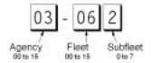
•Agency-Fleet-Subfleet – talkgroup ID’s for EDACS systems are assigned in a way that makes it easy to see at a glance the affiliation of the user. Each radio is assigned a 2-digit agency identifier from 00 – 15. For example, 01 might be used by the police, 02 by ambulance service, 03 by the fire department, and so on. Each agency is then subdivided up to 16 times to provide fleet identification, and then 8 more times to identify subfleets.
For example, the complete AFS for the Police Department West District’s dispatch channel might be 01-062. 01 identifies the agency as the police department, 06 identifies the fleet as the West district, and 02 identifies the subfleet as the dispatch channel. While these assignments are somewhat arbitrary and vary from system to system, there are many resources on the web for finding the assignments for most systems.
Because of the logical hierarchy of the AFS system, your BC796D lets you assign wildcard ID’s that let you, for example, use only one ID memory to identify all units in either an agency or a fleet.
•EDACS SCAT – EDACS SCAT (Single Channel Autonomous Trunking) systems operate on a single channel and alternate control data with analog voice traffic. While your BC796D cannot track ID’s in this system, it can eliminate the control data so that all you hear is the voice transmissions when you monitor this type of system.
8
LTR Trunking
LTR® (Logic Trunked Radio) systems are trunking systems used primarily by business or private communications service providers, such as taxicabs, delivery trucks, and repair services. These systems encode all control information as digital subaudible data that accompanies each transmission, so there is no separate control channel. Users on an LTR system are assigned to specific talkgroups, which are identified by the radio as six digit numbers. These numbers are in the form AHHUUU, where:
A= Area code (0 or 1)
H= Home repeater (01 through 20)
U= User ID (000 through 254)
When the scanner receives a transmission on a channel set to the LTR mode, it first decodes the LTR data included with the transmission. In the ID Search mode, the scanner stops on the transmission and displays the talkgroup ID on the display. In the ID Scan mode, the scanner only stops on the transmission if the LTR data matches a talkgroup ID that you have stored in the bank’s talkgroup ID list and have not locked out.
LTR systems are frequently programmed so that each radio has a unique User ID.
LTR systems also need to be programmed into your scanner in channel-order.
Since many LTR systems use only odd-numbered channel slots, you would program these systems using only the corresponding odd-numbered channels in a bank (for example, you would program a system with channels at 1, 3, 5, and 9 into Trunk 2 channels 101, 103, 105, and 109).
Understanding Banks and Channels
The memory in your scanner is organized into 10 banks of 100 channels each. Each bank can contain conventional channels as well as 1 trunking system. For each trunking system, each bank can also store 10 groups of 10 talkgroup ID’s (100 per bank).
9

Getting More Information
By itself, this manual really only provides part of what you need to know to have fun scanning – how to program and use the scanner. The two supplied Conventional and Trunking frequency guides will give you a good head start on the other part of what you need to know – what frequencies have interesting content. You can also find a wealth of information on the Internet...check out scanners.uniden.com for the latest frequency information in your area.
In addition, you can contact the following source of frequency information:
•Scanner Master
(800) 722-6701 (Hours are from 10:00 a.m. to 5:00 p.m. Eastern Time Monday through Friday.)
To purchase another copy of the conventional or trunking frequency guide, contact one of the following:
•Uniden Parts Department
(800) 554-3988 (Hours are from 8:00 a.m. to 5:00 p.m. Central Time Monday through Friday.)
•Your Local Dealer
10
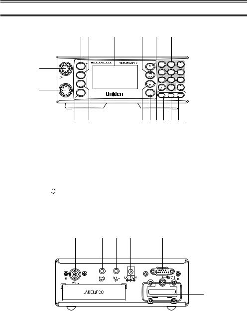
Front and Rear View
3 |
4 |
5 |
6 |
7 |
8 |
VOLUME
|
SCAN |
|
1 |
SRVC |
MODE |
|
||
|
SQUELCH |
|
|
CHAN/FREQ |
|
|
SRCH |
|
2 |
MENU |
BC796D |
|
BACK
VFO/SELECT PUSH
9 10
1.Volume/Squelch Control
2.VFO/Select Channel/Frequency Control
3.Scan Key (SCAN)
4.Service Key (SRVC)
5.Display
6.Resume Key ( RSM )
7.Hold/Up/Manual Key (▲/HOLD)
8.Numeric Keypad
9.Menu/Bank Key (MENU)
|
MANUAL |
1-100 |
101-200 |
201-300 |
|
2 |
|
3 |
|
|
1 |
|
||
|
HOLD |
301-400 |
401-500 |
501-600 |
|
4 |
5 |
|
6 |
|
RSM |
601-700 |
701-800 |
801-900 |
|
7 |
8 |
|
9 |
|
LIMIT |
RVRS |
901-1000 |
SELECT |
1000 |
|
0 |
|
E |
TRUNK |
PRI |
TRNFR |
||
CHANNEL |
L/O |
|||
MUTE
1112 13 14 15 16 17
10.Search Key (SRCH)
11.Limit/Down Key (LIMIT/▼)
12.Trunk Key (TRUNK)
13.Decimal/Reverse Key ( )
)
14.Lockout Key (L/O)
15.Priority Key (PRI)
16.Transfer/Mute Key (TRNFR)
17.Enter/Select Key (E)
18 |
19 |
20 |
21 |
22 |
|
|
|
EXPANSION SLOT |
23 |
|
|
|
|
|
18. |
Antenna Connector |
20. |
External Speaker Jack |
|
19. |
Tape Recorder Output Jack |
21. |
DC Power Jack |
|
|
|
22. |
Remote Control Terminal |
|
|
|
23. |
Expansion Slot |
|
11

Display Icons
ICON |
DESCRIPTION |
PPriority Channel Indicator
L/O |
Lock Out Mode Indicator |
|
Scan/Search Direction Indicator |
|
|
SRCH |
Chain Search Mode Indicator |
SRVC |
Service Search Mode Indicator |
|
|
SCAN |
Scan Mode Indicator |
|
|
ID SCAN |
ID Scan Mode Indicator |
ID SEARCH |
ID Search Mode Indicator |
C |
Channel Type |
|
Conventional Type |
|
Trunk Type |
MMotorola Tracking Type
LLTR Tracking Type
EEDACS Tracking Type
DAT |
Control Channel Data |
||||||
LNK |
Voice Channel Data |
||||||
|
|
|
|
|
|
|
|
P25 |
Digital Communications |
||||||
P25: APCO Project 25 |
|||||||
|
|
|
|
|
|
||
|
|
|
|
|
|
|
|
AM,FM |
Receiving Mode Indicators |
||||||
WFM,NFM |
|||||||
|
|||||||
|
|
|
|
|
|
|
|
|
|
|
|
|
|
Signal Meter |
|
|
|
|
|
|
|
||
12

Included With Your Scanner
If any of these items are missing or damaged, immediately contact your place of purchase or Uniden Customer Service at: (800) 297-1023, 8:00 a.m. to 5:00 p.m., Central Time, Monday through Friday.
•BC796D Scanner
•AC Adapter (AD 580D)
•Cigarette Cord
•DC Cord
•Mounting Bracket
•Telescopic Antenna
•Operating Guide
•Trunk Tracker Frequency Guide
•Other Printed Material
•BC796D SS CD-ROM
13

Setting Up Your Scanner
Connecting an Antenna
You must install an antenna before you can operate the scanner. You have been provided a standard telescopic antenna that works well with this scanner, but you may want to purchases another type to increase the range. To connect the telescopic antenna, simply connect it to the BNC type ANT. connector on the rear of the scanner. You can purchase a variety of scanner antennas for both mobile and base station available at a local electronics store. Choose the one that best meets your needs.
When deciding on a mobile or base station antenna and its location, consider these points.
•The antenna should be as high as possible on a vehicle or a house.
•The antenna and its cable should be as far as possible from sources of electrical noise (ignition systems, gauges, and so on).
•The antenna should be vertical for the best performance.
Mounting an Antenna
Once you choose an antenna, follow the mounting instructions supplied with the antenna. Then route the antenna cable to the scanner.
The antenna connector on your scanner makes it easy to use the scanner with a variety of antennas, such as an external mobile antenna or an outdoor base station antenna.
Always use 50 ohm coaxial cable, such as RG-58 or RG-8, to connect an outdoor antenna. For lengths over 50 feet, use RG-8 low-loss dielectric coaxial cable If your antenna’s cable does not have a BNC connector, you will also need a BNC adapter (available at a local electronics store).
Follow the Installation instructions supplied with the antenna, route the antenna cable to the scanner, then connect it to the ANT. jack.
Warning: Use extreme caution when you install or remove an outdoor antenna. If the antenna starts to fall, let it go! It could contact overhead power lines. If the antenna touches a power line, contact with the antenna, mast, cable, or guy wires can cause electrocution and death. Call the power company to remove the antenna. DO NOT attempt to do it yourself.
Optional Antenna
If you have chosen an optional mobile antenna, connect the antenna plug into the ANT. connector on the rear of the scanner. (For more information on antenna installation, please refer to the instruction guide that came with your antenna.)
14
Typical Mounting Methods
The BC796D can be conveniently mounted on a table, bulkhead, overhead, or any other desired location (refer to figure below for typical mounting methods).
Caution: Make sure there are no hidden electrical wires or other items behind the desired location before proceeding. Check that free access for mounting and cabling
is available.
• Table top mount |
• Bulkhead mount |
• Overhead mount |
Mounting the Scanner in Your Vehicle
Before you mount the scanner, make sure you have all the necessary materials. Then confirm that the scanner fits your vehicle’s mounting area. This unit requires a mounting area of 2-3/8 inch high by 6-15/16 inch wide by 6-9/16 inch deep (61 x 176.5 x 167 mm).
Caution: Be sure to avoid obstructions behind the mounting surface.
Follow these steps to mount the scanner in your vehicle.
1.Choose a mounting location, then use the supplied mounting bracket as a template to mark the positions for
the mounting screw holes.
2. In the marked positions, drill holes slightly smaller than the supplied screws.
3. Attach the mounting bracket to the mounting location using the supplied screws and lock washers.
4. Attach the scanner to the mounting bracket using the supplied mounting knobs.
5. Connect the antenna’s cable to the ANT. connector on the back of the scanner.
Note: If the antenna cable’s connector does not fit in the ANT. connector, you might also need a Motorola-to BNC antenna plug adapter (available at a local
electronics store).
15
Applying Power for Vehicle Installation
You can power your scanner using either the supplied DC power cord or your vehicle’s cigarette lighter socket using DC cigarette lighter power cord.
Caution: You must use a power source that supplies 13.8 V DC and delivers at least 700 mA. Your standard 12 V car battery should be sufficient. The cord connector’s center tip must be set to positive and its plug must fit the scanner’s
DC 13.8 V jack. The supplied DC power cord meets these specifications. Using a power cord that does not meet these specifications could damage the scanner or the adapter.
•Always connect the adapter or DC power cord to the scanner before you connect it to the power source. When you finish, disconnect the adapter or DC power cord from the power source before you disconnect it from the scanner.
•For added safety and to protect your scanner, disconnect the cable from your vehicle battery’s
negative (-) terminal before you begin.
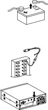
Follow these steps to connect the supplied DC power cord.
1.Connect the power cord’s black wire to a chassis ground, such
as a metal screw attached to a metal part of the vehicle’s frame. Be sure that the screw is not insulated from the frame by a plastic part.
2.Connect the power cord’s red wire (with in-line fuse) to a source
of voltage that turns on and off with the ignition switch, such as a spare accessory terminal in your vehicle’s fuse box.
3. Insert the power cord’s barrel plug into the DC 13.8 V jack on the back of the scanner.
4.Reconnect the cable to the vehicle battery’s negative (-) terminal.
To power the scanner from a vehicle’s 12 V power source (such as a cigarette-lighter socket), you need a cigarette-lighter adapter.
To connect an optional DC cigarette-lighter power cable, insert
its barrel plug into the DC 13.8 V jack on the back of the scanner, then plug the power cable into your vehicle’s cigarette lighter socket.
Note: If you use a cigarette-lighter power cable and your vehicle’s engine is running, you might hear electrical noise from the engine while scanning. This is normal.
16
Desktop Installation
You can place this scanner on a desk, shelf, or table to use it as a base station.
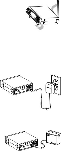
1. Flip up the feet for desk installation.
2. Extend the antenna to full vertical position. Adjust the angle for best reception.
Applying Power Using Standard AC Power
To power the scanner from an AC outlet, use the provided AC adapter with a 5.5 mm outer diameter/2.1mm inner diameter tip.
Caution: You must use a Class 2 power source that supplies 13.8 V DC and delivers at least 700 mA. The cord connector’s center tip must be set to positive and its plug must fit the scanner’s DC 13.8 V jack. Using an adapter that does not meet these specifications could damage the scanner or the adapter.
•Always connect the AC adapter to the scanner before you connect it to AC power. When you finish, disconnect the adapter from the AC power before you disconnect it from
the scanner.
1.Insert the adapter’s barrel plug into the DC 13.8 V jack on the back of the scanner.
2.Plug the adapter into a standard AC outlet.
Note: Use only the AC adapter supplied with your scanner.
1 |
3.8V |
|
Connecting an External Speaker
In a noisy area, an external speaker (available at a local electronics store) positioned in the right place might provide more comfortable listening.
Plug the speaker cable’s 1/8 inch (3.5 mm) plug into your scanner’s EXT. SP. jack.
Note: Connecting an external speaker disconnects the scanner’s internal speaker.
Connecting an Earphone
For private listening, you can connect an earphone with a 1/8 inch (3.5 mm) plug to the
EXT. SP. jack on the back of the scanner. Be very careful as damage to your hearing can result if the VOLUME control is not set to the lowest level first. See below for "Listening Safely" instructions. (Your local electronics store should carry a wide selection of earphones.) Once the earphone is connected, it will automatically disconnects the internal speaker.
17
Listening Safely
To protect your hearing, follow these guidelines when you use an earphone or headphones.
•Do not use the earphone to listen to the WX alert siren test or when in SAME Alert mode. The alert tone's volume is not adjustable and damage to your hearing could occur.
•Do not listen at extremely high volume levels. Extended high volume listening can lead to permanent hearing loss.
•Set the VOLUME to the lowest setting before you begin listening. After you begin listening, adjust the VOLUME to a comfortable level.
•Once you set the VOLUME, do not increase it. Over time, your ears adapt to the volume level, so a volume level that does not cause discomfort might still damage your hearing.
Connecting the Clone Cable
You can transfer the programmed data to and from another BC796D scanner using a RS232C Cable (9 pin to 9 pin) (not supplied). Connect the cable between each scanner’s REMOTE jacks. See "Clone Mode" on page 73. You can also upload or download the programmed data to or from a PC using an optional PC interface kit available through your local electronics store.
Connecting the Tape Recorder
You can use a standard tape recorder or a VOX (Voice Operated Control) recorder. To connect the recorder to the scanner, connect a cable with a 1/8 inch (3.5 mm) plug from the tape recorder’s remote jack to the TAPE OUT jack on the back of the scanner. (Your local electronics store should carry a wide selection of cables and tape recorders.)
Remember!
•You must mark a channel, ID, talkgroup, or bank for Recording in order for this feature to work.
•This feature does not work if your scanner is set with MUTE ON.
To set the record for the channel.
2:SCAN OPTION → 1:CONVENTIONAL → select the channel number, then press E.
→ 8:RECORD → 1:ON
To set the record for the search.
1:SERVICE OPTION → :CHAIN SEARCH → 6:RECORD → 1:ON
To set the record for talkgroup ID.
2:SCAN OPTION → 2:TRUNK → select the bank, then press E → 3:TALK GROUP
→ select ID LIST, then press E → 3:RECORD → 1:ON
To set the record for ID Searching (see “Searching for Active Talkgroups”),
2:SCAN OPTION → 2:TRUNK -> select the bank, then press E → 5:RECORD → 1:ON
18
Basic Operation
This section is your main reference for using the scanner once you have programmed conventional and trunked systems. Note that there are some slight differences to some functions depending on whether you are trying to affect conventional operation or trunked operation. Be sure to refer to the appropriate section depending on the mode you are using.
Turning On the Scanner
Turn the VOLUME control clockwise out of the detent position. The scanner automatically starts scanning. Since there are no frequencies programmed in your scanner initially, you may not receive any signals. Once you set the squelch and program some frequencies, you will begin hearing conversations regularly.
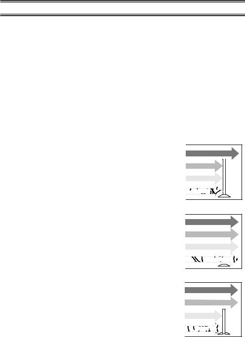
Setting the Squelch
To set the squelch, you must be in the hold mode, and you should not be receiving a signal on your scanner.
1.Press ▲/HOLD until you do not hear a signal.
2.Make sure that the VOLUME is set to a comfortable listening level.
3.Think of the Squelch Control as a gate. Turn the SQUELCH control fully counterclockwise. This raises the “Squelch Gate” so high that only very strong signals can get through.
4.Turn SQUELCH clockwise until you hear a hiss. This lowers the “Squelch Gate” so that everything gets through – noise, weak signals, medium signals and strong signals.
5.Turn SQUELCH back counter-clockwise just until the hiss stops. Now the “Squelch Gate” allows only clear signals through.
Note: For Trunk Scanning, a good squelch setting is critical. The recommended setting is midpoint. If you set the squelch too high, the scanner might not reliably stop on the control channel.
STRONG SIGNALS |
MEDIUM SIGNALS |
WEAK SIGNALS |
NOISE |
STRONG SIGNALS |
MEDIUM SIGNALS |
WEAK SIGNALS |
NOISE |
STRONG SIGNALS |
MEDIUM SIGNALS |
WEAK SIGNALS |
NOISE |
19
Using the Menu
Many of your scanner’s functions are accessed through its menu system. For complete information about a menu option, see the section referencing its use. A complete list of the menu structure is included in the back of this manual. To select a menu item, first press MENU to go to the first-level menu. Then, either press the number key corresponding to the option you want to select, or use the scroll bar to highlight the option then press E.
To back up a menu level, press MENU.
Notes: • To change a setting that affects either a specific bank or channel, first select a channel within the bank or the channel that you want to modify.
•To check the settings for a channel, press and hold MENU for 2 seconds.
In this manual, we represent navigation through the menu with the following notation:
MAIN MENU → SUB MENU 1 → SUB MENU 2
For example to access the DIMMER LIGHT option, the notation is:
3:SYSTEM OPTION → 1:DIMMER
To access this option, press MENU, then scroll to each menu option and press E. Or, press MENU, 3, 1.
•Some menu items are not numbered. To access these options, you must manually navigate to the selection using the scroll bar.
Manually Selecting a Channel
To manually select a channel, press ▲/HOLD, the channel number, then ▲/HOLD again. The scanner displays the information stored in that channel.
Notes: • If the channel contains trunked system information, frequency data is not displayed.
•If you are trunk scanning, you need to first press TRUNK to exit the trunking mode.
Scanning Programmed Channels
Before you can scan, you must first program channels. See the appropriate programming section for complete instructions.
To begin scanning, simply turn on your scanner or, if the scanner is not currently scanning, press SCAN. The scanner checks each system you have programmed that is not locked out and stops if there is activity. SCAN scrolls across the display, right to left.
When the scanner receives a signal on a programmed channel, it stops on that channel and displays the channel information (text tag, channel number, trunk mode).
Locking/Unlocking Banks
When you are scanning conventional banks, the scanner displays the digit corresponding to all unlocked banks. To lock out a bank so that the scanner does not scan its channels, press the number that corresponds to the bank. The scanner replaces that bank’s number with a dash.
20
 Loading...