


Model PAR-2-F / PAR-3-F Gas Fryer
Operation Instructions
302 Spencer Lane • P.O. Box 5369 |
San Antonio, Texas 78201 |
(800) 525-8130 • (210) 731-5000 • Fax: (210) 731-5099
PREFACE
This manual was rewritten and published by the Technical Publications Department, Ultrafryer Systems, for use by personnel who operate an Ultrafryer Model Gas Fryer equipped with an Ultrastat 21 or Ultrastat 25 Cooking Computer. This manual complements, and should be used in conjunction with the applicable Ultrafryer Cooking Computer Operations manual.
TECHNICAL PUBLICATIONS DEPARTMENT ULTRAFRYER SYSTEMS
302 SPENCER LANE SAN ANTONIO, TX 78201 1-800-545-9189 EXT. 5007
NOTE: This manual is applicable to “Standard” Gas Models Par-2-F / Par-3-F Gas Fryers. It can be used as a guide in operating special variations of a Par-2-F / Par-3-F Gas Fryer. Replaces Ultrafryer Gas Fryer M&R Manual PN 30A012 and Addendum PN 30A046.
30A067 REVISED APRIL 2003
i
TABLE OF CONTENTS |
Page |
|
GENERAL INFORMATION |
||
|
||
WARRANTY |
2 |
|
SAFETY |
3 |
|
DESCRIPTION / SPECIFICATION |
3 |
|
INSTALLATION, INITIAL CLEANING, SHORTENING INSTALLATION, |
|
|
AND FRYER TEST START-UP |
|
|
INSTALLATION |
5 |
|
GENERAL |
5 |
|
UNPACKING |
5 |
|
INSTALLING |
5 |
|
LEVELING |
7 |
|
INLET GAS REQUIREMENTS |
8 |
|
GAS CONNECTION |
9 |
|
ELECTRIC CONNECTION |
9 |
|
INITIAL CLEANING |
9 |
|
FRYER TEST START-UP |
10 |
|
SHORTENING INSTALLATION |
12 |
|
INLET GAS LINE SIZING TABLE |
13 |
|
PREVENTIVE MAINTENANCE AND TROUBLE SHOOTING |
|
|
PREVENTIVE MAINTENANCE |
16 |
|
TROUBLE SHOOTING |
16 |
|
FRYER OPERATION |
|
|
GENERAL |
19 |
|
FILTER TUB ASSEMBLY |
19 |
|
ULTRASTAT 21 COOKING COMPUTER OPERATION |
21 |
|
START-UP & COOKING |
21 |
|
FILTERING SHORTENING |
22 |
|
SHORTENING DISPOSAL & FRYER BOIL-OUT |
24 |
|
ULTRASTAT 25 COOKING COMPUTER OPERATION |
26 |
|
START-UP & COOKING |
26 |
|
FILTERING SHORTENING |
26 |
|
SHORTENING DISPOSAL & FRYER BOIL-OUT |
28 |
|
CLEANING |
32 |
|
MAINTENANCE |
36 |
|
SERVICE & PARTS |
|
|
TECHNICALASSISTANCE |
40 |
|
ORDERING INFORMATION |
40 |
|
PARTS IDENTIFICATION |
40 |
|
WIRING DIAGRAM |
50 |
i i
GENERAL INFORMATION
1

ULTRAFRYER® LIMITED WARRANTY
Ultrafryer Systems warrants to the original purchaser of a gas or electric Ultrafryer® sold within the United States, it’s territories and Canada, that it will be free of defects in material and workmanship for the periods listed below: STAINLESS STEEL FRYER VAT – Stainless Steel fryer vats are warranted for (10) ten years upon the terms hereinafter described. The (10) ten year warranty coverage applies ONLY to the Stainless Steel fryer vat and does not apply to the other
components such as controls, fire boxes, gaskets, mounting hardware, or the heat shield weldment. The (10) ten year limited warranty coverage for the Stainless Steel fryer vats are as follows: (1) Vats that fail due to faulty workmanship or materials within the first twelve (12) months from the date of initial start up will be exchanged at no cost. Standard delivery ground freight will be prepaid by Ultrafryer Systems for first year failures only. The cost of labor to install the replacement vat will be covered by Ultrafryer Systems for vats, which fail within twelve (12) months from the date of initial start up. Labor for vat replacements after the first year is the responsibility of the owner.
(2) Vats that fail within the first (18) months will be exchanged at a cost not to exceed $100.00 FOB San Antonio. (3) Vats that fail within the first (24) months will be exchanged at a cost not to exceed $150.00 FOB San Antonio. (4) Vats that fail within the next (8) years will be exchanged at a cost not to exceed $200.00 FOB San Antonio. (Subject to inflation adjusted in accordance with the C.P.I.). Proper credit issue for vat failures is contingent upon receipt, by Ultrafryer Systems, of the serial number identification tag for any failed vat.
ULTRAFRYER PARTS – All parts on the Ultrafryer® are covered for a period of one (1) year from the initial date of start up. This is to include computers, gas valves, switches, thermostats, etc. Ultrafryer Systems reserves the right to charge for certain parts such as computers, filter pumps and motors or any item over the amount of $100.00 until Ultrafryer Systems receives the defective part back. After inspection, credit for the part will be issued to the purchaser provided the part is deemed defective and that defect is not the result of neglect or abuse by the user. The shortening filtration system, (hoses) are warranted for ninety (90) days from the initial date of start up.
PROCESSING WARRANTY CLAIMS – The equipment owner must promptly notify Ultrafryer Systems Warranty
Department of any alleged defects as soon as they are discovered by calling 1-800-525-8130. After such notice, the Warranty Department will perform its obligation under this warranty within a commercially reasonable period of time. If alleged defects develop after normal business hours, on weekends or on holidays the owner must call Ultrafryer Systems first at the above number. This number is monitored 24 hours a day, 7 days a week. Ultrafryer Systems will notify an authorized service
agent to make repairs during normal hours or after hours. Any parts that need to be shipped back to Ultrafryer Systems will be shipped back prepaid by the customer marked with the processing number and to the attention of the WARRANTY DEPARTMENT.
NON WARRANTY COVERAGE – This warranty does not include coverage for any consequential cost of damages including, but not limited to, any loss in store sales, spoiled food products, transportation, duty or custom cost. This warranty does not cover the Ultrafryer® exported to countries outside the United States and its territories. This warranty does not cover original installation and adjustments such as leveling, calibrations, electrical and gas connections, or problems due to faulty or contaminated gas supply. This warranty does not cover travel over 100 miles or 2 hours driving time from the location of the Ultrafryer® or overtime or holiday charges unless the Warranty Department granted prior approval. This warranty does not cover damage due to misuse, abuse, alteration or accident. This Warranty does not cover improper or unauthorized repair or installation, damage in shipment, normal maintenance items such as gaskets, hoses, and exterior finishes. Ultrafryer
Systems reserves the right to void component part warranty on any Ultrafryer® that is stored more than 6 (six) months after shipment from Ultrafryer Systems and not put into service.
LABOR COVERAGE – The cost for labor to replace parts are covered for one (1) year after the initial start up. This warranty will include the labor involved in the six (6) month and the twelve (12) month fryer inspections recommended by the manufacturer for the first year after initial start up. The Warranty Department must be promptly notified of any defects within the first year of operation. The labor warranty does not include the cost to repair or clear dirty filter systems or perform any adjustments that would normally fall under the tasks associated with a proper start up and/or demonstration.
Labor is covered by Ultrafryer Systems for repairs by an AUTHORIZED service agent. Owner is responsible for all costs associated with fryer installation and start up unless prior arrangements have been made with Ultrafryer Systems.
DISCLAMIER OF WARRANTIES
Other than as stated herein ULTRAFRYER SYSTEMS makes no warranty of any kind, express or implied, including but not limited to any warranty of merchantability of fitness for a particular purpose, including trade usage. Ultrafryer Systems sole obligation, and purchaser’s sole remedy, under this warranty is repair or replacement, at the discretion of Ultrafryer Systems, of any part or component that proves to be defective in materials or workmanship. In no event shall Ultrafryer Systems be liable for consequential, incidental, or special loss or damages arising from the use of, or inability to use, the ULTRAFRYER®.
This limited warranty is the only and complete statement with respect to warranties of NEW Ultrafryer® PAR-2, PAR-3 Gas and Electric ULTRAFRYERS® sold after March 1st, 2001. There are no other documents or oral statements for which Ultrafryer Systems will be responsible.
2
SAFETY
The major safety factor associated with the Ultrafryer Par-2-F / Par-3-F Gas Fryer is burns from hot shortening. In order to prevent serious burns, good housekeeping habits are required. The floor in front of and the area around the fryer should be kept clean and dry. Whenever anything is placed in to a fryer vat, care should be used not to splash the hot shortening. Product should always be “PLACED” into the shortening, not thrown. Safety goggles, neoprene insulated gloves and an apron must be worn while filtering or boiling-out a fryer vat. Electrical controls on all Ultrafryer Fryers operate on 120 volts single phase electrical power. No adjustments or replacement of electrical controls should ever be attempted without first disconnecting electrical power. The fryer should never be operated with wet hands or while standing in water. To do so can result in serious electrical shock or death.
The Ultrafryer Model Par 2-F / Par-3-F Gas Fryer is equipped with the following safety features: 1) High Limit Thermostat to shut off gas to the burners by opening a solenoid=actuated safety valve in the combination gas control valve. 2) Combination gas control valve which includes a built-in pressure regulator and manual valve. 3) Par-2-F gas Fryers have a CENTRIFICAL switch and Model Par-3-F Gas Fryers have an AIR PRESSURE switch to open the 24 volt electrical circuit to the Combination Gas Control Valve to turn the gas to the fryer OFF, should the Blower Motor fail. 4) Sensing circuit within the Spark Ignitor Module to turn the fryer OFF if a burner FLAME-OUT occurs. 5) A Drain Valve Safety Switch that will DISABLE the fryer each time the shortening drain valve is OPENED.
DESCRIPTION/SPECIFICATIONS
The Ultrafryer Par-2-F / Par-3-F Gas Fryer is constructed from 16 and 18 gauge, type 304 polished satin finish stainless steel. Most Models Par-2-F / Par-3-F gas fryers are equipped with a Model Ultrastat 21 or 25 Cooking Computers; however customers may request the fryer be equipped with a Default-To-Manual-Restart (DTMR) Control or an Ultrastat 11 Cooking computer. In addition, the Par-2-F / Par-3-F fryer has a shortening filtration system that uses a Permafil Stainless Steel Filter Screen. The Customer has the option of ordering a Magnepad Filter System that uses a Paper Filter Pad in lieu of the S/S filter screen. The dimensions, specifications and gas rating of a model PAR-2-F / PAR-3-F Gas Fryer is as follows:
A. Par-2-F |
|
|
|
|
|
|
|
|
|
|
|
|
|
|
|
|
||||
ITEM DESCRIPTION |
|
|
|
PAR-2-18-F |
|
|
|
|
|
PAR-2-20-F |
|
|
|
|||||||
|
|
|
|
|
in. |
(mm) |
|
|
in. |
(mm) |
|
|
|
|||||||
|
|
|
|
|
|
|
|
|
|
|
||||||||||
|
|
Overall Width |
|
|
|
191⁄2” |
(495) |
|
|
|
|
211⁄2” |
(546) |
|
|
|||||
|
|
Overall Depth |
|
|
|
363⁄4” |
(933) |
|
|
|
|
383⁄4” |
|
(984) |
|
|
||||
|
|
Work Height |
|
|
|
36” |
(914) |
|
|
|
|
|
|
36” |
|
(914) |
|
|
||
|
|
Oil Capacity |
|
|
|
|
|
|
|
|
|
|
|
|
|
|
|
|
|
|
|
|
High Level |
|
|
110 lbs |
(55 liters) |
|
|
|
|
138 lbs |
(69 liters) |
|
|
||||||
|
|
Low Level |
|
|
|
70 lbs (35 liters) |
|
|
|
|
|
-- |
|
|
|
|
|
|||
|
|
Size Vat Container |
|
18” x 18” |
(457 x 457) |
|
|
20” x 20” (508 x 508 ) |
|
|
||||||||||
|
|
Gas Rating |
|
|
|
|
|
|
|
|
|
|
|
|
|
|
|
|
|
|
|
|
Butane Gas |
|
65,000 BTU/Hr (71.5 MJ/Hr.) |
|
75,000 BTU/Hr (82.5 MJ/Hr.) |
|
|
||||||||||||
|
|
Natural Gas |
|
65,000 BTU/Hr (71.5 MJ/Hr.) |
|
75,000 BTU/Hr (82.5 MJ/Hr.) |
|
|
||||||||||||
|
|
Propane Gas |
|
65,000 BTU/Hr (71.5 MJ/Hr.) |
|
75,000 BTU/Hr (82.5 MJ/Hr.) |
|
|
||||||||||||
|
|
Shipping Cube |
|
|
17.15 ft3 |
(.48 m3) |
|
|
|
19.89 ft3 |
(.56 m3) |
|
|
|||||||
|
|
Shipping Weight |
|
|
315 lbs |
(142 kgs) |
|
|
|
325 lbs |
(146 kgs) |
|
|
|||||||
|
|
Electrical Requirements |
|
|
|
120 VAC 6 Amps |
|
|
|
|
|
120 VAC 6 Amps |
|
|
||||||
|
|
|
|
|
60 Hz 1 Ø |
|
|
|
|
|
60 Hz 1 Ø |
|
|
|
||||||
|
|
|
|
|
|
|
|
|
|
|
|
|
|
|||||||
B. Par-3-F |
|
|
|
|
|
|
|
|
|
|
|
|
|
|
|
|
|
|
|
|
|
|
PAR-3-14-F |
|
|
|
|
|
PAR-3-18-F |
|
|
|
PAR-3-20-F |
||||||||
|
|
ITEM DESCRIPTION |
|
|
|
|
|
|
|
|
|
|||||||||
|
|
|
in. |
|
(mm) |
|
|
|
|
in. |
|
(mm) |
|
|
in. |
(mm) |
||||
|
|
|
|
|
|
|
|
|
|
|
|
|||||||||
|
|
Overall Width |
|
151⁄2” (394) |
|
|
|
|
191⁄2” |
(495) |
|
|
|
|
211⁄2” |
(546) |
||||
|
|
Overall Depth |
|
323⁄4” |
(832) |
|
|
|
|
363⁄4” |
|
(933) |
|
|
|
383⁄4” |
(984) |
|||
|
|
Work Height |
|
36” |
|
(914) |
|
|
|
|
36” |
|
(914) |
|
|
|
|
36” |
(914) |
|
|
|
Oil Capacity |
|
|
|
|
|
|
|
|
|
|
|
|
|
|
|
|
|
|
|
|
High Level |
45 lbs |
(22.5 liters) |
|
|
|
110 lbs |
(55 liters) |
|
|
|
138 lbs |
(69 liters) |
||||||
|
|
Low Level |
35 lbs |
(17.5 liters) |
|
|
|
70 lbs |
(35 liters) |
|
|
|
|
|
-- |
|||||
|
|
Size Vat Container |
14” x 14” (357 x 357) |
|
|
18” x 18” |
(457 x 457) |
|
20” x 20” (508 x 508 ) |
|||||||||||
|
Gas Rating |
|
|
|
|
|
|
|
|
|
|
|
|
|
|
|
|
|
|
|
|
|
Butane Gas |
90,000 BTU/Hr (99 MJ/Hr.) |
|
110,000 BTU/Hr (121 MJ/Hr.) |
|
120,000 BTU/Hr (132 MJ/Hr.) |
|||||||||||||
|
|
Natural Gas |
90,000 BTU/Hr (99 MJ/Hr.) |
|
110,000 BTU/Hr (121 MJ/Hr.) |
|
120,000 BTU/Hr (132 MJ/Hr.) |
|||||||||||||
|
|
Propane Gas |
90,000 BTU/Hr (99 MJ/Hr.) |
|
110,000 BTU/Hr (121 MJ/Hr.) |
|
120,000 BTU/Hr (132 MJ/Hr.) |
|||||||||||||
|
|
Shipping Cube |
12.11 ft3 |
(.34 m3) |
|
|
17.15 ft3 |
(.48 m3) |
|
|
19.89 ft3 (.56 m3) |
|||||||||
|
|
Shipping Weight |
275 lbs |
|
(124 kgs) |
|
|
315 lbs |
(142 kgs) |
|
|
325 lbs |
(146 kgs) |
|||||||
|
|
Electrical Requirements |
|
120 VAC 6 Amps |
|
|
|
120 VAC 6 Amps |
|
|
|
120 VAC 6 Amps |
||||||||
|
|
|
60 Hz 1 Ø |
|
|
|
|
|
60 Hz 1 Ø |
|
|
|
|
60 Hz 1 Ø |
||||||
|
|
|
|
|
|
|
|
|
|
|
|
|
||||||||
NOTE: TEST START-UP, OPERATION, COOKING, FILTERING AND BOIL-OUT PROCEDURES OFA MODEL PAR-2-F / PAR-3-F GAS FRYER IN THIS MANUAL ARE BASED ON ULTRASTAT 21 AND 25 COOKING COMPUTER PROCEDURES, REFER TO MANUAL PN 30A053, ULTRASTAT 11 COOKING COMPUTER OPERATION INSTRUCTION OR 30A066, DEFAULT-TO-MANUAL-RESTART (DTMR) CONTROL OPERATION INSTRUCTION TO PERFORM THESE FUNCTIONS IN A FRYER EQUIPPED WITH THESE CONTROLS.
3
INSTALLATION, INITIAL CLEANING, SHORTENING INSTALLATION AND FRYER TEST START-UP
4
INSTALLATION
GENERAL - Each Model Par-2-F / Par-3-F Gas Fryers should be installed as follows:
1.Properly unpacked and positioned at its operating location within the store.
2.Placed beneath a properly designed exhaust hood and protected by a Fire Suppression System
3.LEVELED using a spirit level to assure each vat contains the proper amount of shortening.
4.Installed by a licensed electrician and plumber.
5.Connected to the type gas for which the unit was fabricated as shown on the rating plate.
6.Connected to the proper size pressure regulator installed in the gas supply line and adjusted to the proper manifold pressure.
7.Connected to the main gas supply line with the proper size gas line.
8.Restrained by use of a restraining device to avoid splashing hot liquid and to ensure tension cannot be placed on electrical or gas connections.
UNPACKING - Check that the container is upright. Use an outward prying motion. DO NOT USE A HAMMER to remove the wood braces and carton. Check the fryer bank for visible damage; if damage has occured do not refuse shipment, but contact the carrier and file the appropriate freight claims. Remove the two shipping bolts in the front and rear legs and remove the two 2” x 6” (51mm x 152mm) wood supports.
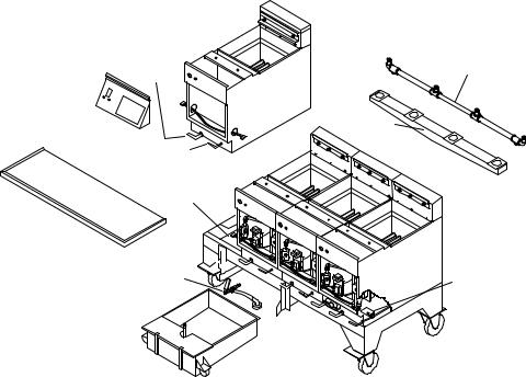
INSTALLING - If sufficient clearance is available to roll the assembled fryer bank into the building, proceed to the paragraph below. In the event entrance doors are too narrow to roll the assembled fryer into the building; disassemble and reassemble the fryer as follows:
|
|
|
|
|
|
|
|
||
|
||
|
||
|
|
|
|
|
|
|
|
|
|
|
|
|
||
|
||
|
||
|
|
DIS-ASSEMBLY
A.Perforrn the following steps facing the FRONT of the fryer:
1.Number each vat cabinet from LEFT to RIGHT and place these numbers on the front and rear panel of each cabinet.
2.Lower the Temperature Control access panel from each vat cabinet.
3.CAREFULLY remove the APRON from the fryer bank by removing the two (2) 1⁄4 - 20 wing nuts, 1⁄4” (6mm) split washers, and n” (18mm) flat washers from each 1⁄4 - 20 weld stud beneath each cabinet hat section.
NOTE: It may be necessary to cut the SILICONE SEAL between the apron and vat cabinets to separate the apron.
DO NOT DAMAGE THE GASKET.
4.Remove the JOINER STRIP located between each set of vats; then cut the SILICONE SEAL between the vats.
5.CAREFULLY separate the SHORTENING DRAIN TROUGH from each 2” (51mm) ball valve plate by removing the four (4) 1⁄4 - 20 hex head bolts and nuts; then remove the drain trough from the fryer.
5
6.CAREFULLY disconnect the 4 PIN WHITE connector from its mating receptacle located on the LOWER right hand end of each vat; then remove the BLACK wiring harness protector from the 2” (51mm) opening in each vat.
7.CAREFULLY disconnect the ELECTRICAL OUTLET BOX BLACK and WHITE electrical wires connected to wires by WIRE NUTS located on the LEFT HAND side of the “extreme” RIGHT HAND vat.
8.Remove the 10-24 truss head screw and nut on the right hand side of each vat used to secure adjoining vats and remove the 10-24 truss head screw and nut that secures the “extreme” left hand vat cabinet to the base frame.
B.Perforrn these steps facing the REAR of the fryer:
1.Remove the REAR panel from each vat by removing the four (4) pan head self-tapping screws.
2.Remove the two (2) 10-24 truss head screws and nuts on the right hand side of each vat used to secure adjoining vats.
3.CAREFULLY remove the two (2) philips head self-tapping screws along the BOTTOM flange of each cabinet.
4.CAREFULLY loosen and separate the flexible gas line from the gas manifold flare fitting on each vat, remove the 1⁄4 - 20 hex head bolts and nuts from each manifold “L” BRACKET; then set the GAS MANIFOLD aside.
5.CAREFULLY disconnect the SHORTENING LINE RED and WHITE heater tape electrical wires terminated in a 3 PIN WHITE connector from its mating receptacle located on the left hand side of the “extreme” LEFT HAND vat.
NOTE: BLACK and WHITE CABLETYES may have to be removed to separate connectors.
6.CAREFULLY disconnect the FILTER PUMP MOTOR RED, GREEN and WHITE electrical wires terminated in a 4 PIN WHITE connector from its mating receptacle located on the left hand side of the “extreme” LEFT HAND vat.
7.CAREFULLY disconnect the POWER LINE BLACK and WHITE electrical wires terminated in a 4 PIN WHITE connector from its mating receptacle located on the left hand side of the “extreme” LEFT HAND vat.
8.SECURE the SHORTENING LINE to the base frame on the LEFT HAND end of the fryer bank; then CAREFULLY loosen and separate the shortening line union attached to each 3⁄4” (19mm) ball valve.
9.CAREFULLY remove each cabinet from the base frame, carry each cabinet into the building; then place the base frame into position in the kitchen.
10.PRIOR to re-assembling the fryer bank:
a.Remove DRIED silicone used to seal the apron to vats, opening between each set of vats, front and rear of each cabinet, lower edge of the two (2) end vats, and perimeter of the base frame.
b.THOROUGHLY clean the TEFLON TAPE from all GAS and SHORTENING fittings and pipes; then wrap all male pipes and fittings with new teflon tape.
RE-ASSEMBLY
A.Place each vat cabinet in numerical order in FRONT of the base frame from LEFT to RIGHT.
B.Install each vat cabinet on the base frame as follows:
1.Place a bead of silicone around the perimeter of the base frame for the FIRST vat cabinet.
2.CAREFULLY place VAT CABINET #1 in position on the base frame; then secure the cabinet to the base frame by installing a 10-24 truss head screw and nut on the left hand flange to the base frame then install two (2) philips head selftapping screws in the two holes on the REAR bottom flange of the cabinet.
3.Repeat the above procedures to install remaining vat cabinets on the base frame.
C.When all vat cabinets are installed on the base frame, secure the cabinets as follows:
1. Place a bead of silicone along the FRONT, TOP and REAR space between vat cabinets #1 and #2.
2.Install a 10-24 truss head screw and nut in the 1⁄4” (6mm) holes on the FRONT right hand side of vat cabinet #1 and left hand side of vat cabinet #2.
6

3.Install two (2) 10-24 truss head screws and nuts in the two (2) x” (5mm) holes on the REAR left hand side of vat cabinet #1 used to secure it to cabinet #2.
4.Repeat the above procedures to secure remaining vat cabinets to adjoining vat cabinets.
D.Perform these steps facing the REAR of the fryer:
1.CAREFULLY connect each shortening line union HAND TIGHT, remove the device used to secure the SHORTENING LINE to the LEFT end of the base frame; then SECURELY tighten each shortening line union.
2.Place the GAS MANIFOLD in position, secure each manifold “L” BRACKET to the frame using the 1⁄4 -20 hex head bolts and nuts removed earlier; then SECURELY connect each manual gas valve flexible gas line to the male flare fitting on the manifold.
3.SECURELY connect the SHORTENING LINE RED and WHITE heater tape electrical wires terminated in a 3 PIN WHITE connector to its mating receptacle on the left-hand side of the “extreme” LEFT HAND vat. Install a small cabletye on the connection to assure these connectors cannot be separated.
4. SECURELY connect the FILTER PUMP MOTOR RED, GREEN and WHITE electrical wires terminated in a 4 PIN WHITE connector to its mating receptacle located on the left-hand side ofthe “extreme” LEFT HAND vat.
5.SECURELY connect the POWER LINE BLACK and WHITE electrical wires terminated in a 4 PIN WHITE connector to its mating receptacle located on the left hand side of the “extreme” LEFT HAND vat.
6.Install a large cabletye on the cable harness on the “extreme” LEFT and RIGHT vats; then replace the REAR PANEL on each vat cabinet using eight (8) pan head self-tapping screws in each cabinet panel and fan cover.
E. Perform these steps facing the FRONT of the fryer:
1.Install the BLACK wiring harness protector in the 2” (51mm) opening of each vat; then SECURELY connect the 4 PIN WHITE wiring harness connector to its mating receptacle on each vat.
2.CAREFULLY connect the ELECTRICAL OUTLET box BLACK and WHITE wires on the “extreme” right hand
vat to the POWER line BLACK and WHITE wires using the wire nuts previously removed.
3.CAREFULLY position the drain trough beneath the fryer; then SECURE the drain trough to each 2” (5mm) ball valve plate using four (4) 1⁄4 - 20 hex head bolts and nuts previously removed.
4.Remove any dried silicone from each JOINER STRIP, place a bead of silicone in each strip; then place the joiner strip over the edge of all adjoining fryer vats.
5.CAREFULLY replace the APRON as follows:
a. Remove any dried silicone from the front edge of each vat cabinet and
the bottom of the APRON.
b.Place a bead of silicone along the FRONT edge of each vat cabinet and fill the REAR corners of the apron with silicone so it will be flush with the top of the apron.
c.Place the apron in position with the REAR flange towards the FRONT inside edge of each vat and the FRONT of the apron, elevated approximately 45 degrees; seat the rear flange of the apron over the front inside edge of each vat; then CAREFULLY lower the front of the apron until each 1⁄4 - 20 weld stud is seated in the notches of the front and rear hat section of each cabinet. Slip the apron a little bit to the left and right to center it on the fryer.
d.When the apron is properly positioned, secure it to the hat sections of each cabinet using the wing nuts, split washers and the flat washers removed earlier.
e.After the apron has been secured to each fryer cabinet apply a small bead of multipurpose sealant to the areas shown to the right.
6.Replace the Temperature Control Access Panel.
LEVELING:
CAUTION: FAILURE TO SEALTHESE AREAS WILL PERMIT HOT SHORTENING TO BOIL UP INTO THE SPACE ALLOWING OILTO SEEP INTO THE FIREBOX AREA.
A.Roll the fryer to its operating location and check to be sure it is level at this location. If not, loosen the casters and insert the appropriate number of shim plates between leg and caster plates then retighten the caster bolts.
B.If the floor is smooth and level, adjust to the high corner and measure with a spirit level. If the floor is uneven or has a decided slope, level the unit with metal shims.
NOTE: A caster may not return exactly to the same position after being moved, which may require re-leveling after each move. C. Connect the gas manifold to the building gas supply line by means of a CSA International APPROVED flexible gas line as
shown in the figure below. |
7 |
|
NOTE: CONNECT-IT inc. 3⁄4” (19mm), 1” (25mm) and 1 1⁄4” (32mm) flexible gas hose 4 feet long (1219mm) with a quick disconnect coupling on one end is available from Ultrafryer Systems under part number 24-322 (3⁄4” (19mm) hose), 24-323 (1” (25mm) hose) and 24-456 (1 1⁄4” (32mm) hose). These hoses are euipped with a fusible link, which melts at 361°F (183ºC) that will SHUT OFF the gas supply when it melts. A restraining device 44” (1119mm) long is also available under part number 24-324.
CAUTION: THE BUILDING GAS SUPPLY LINE MUST BE SIZED TO PROVIDE THE VOLUME OF GAS REQUIRED FOR PROPER OPERATION AS EXPLAINED ON TABLE 1, page 13.
WARNING: |
THE RESTRAINT DEVICE (ITEM 9) MUST BE INSTALLED TO ASSURE TENSION CANNOT BE |
|||
|
|
PLACED ON THE FLEXIBLE GAS LINE OR FITTING. |
||
1. |
BUILDING GAS SERVICE LINE |
6. |
APPLIANCE MANIFOLD/NIPPLE |
|
2. |
MAIN GAS CUT-OFF VALVE |
7. |
EYELET FASTENERS |
|
3. |
CONNECT-IT QUICK-DISCONNECT |
8. |
SPRING HOOK |
|
4. |
FLEX-CON CONNECTOR |
9. |
RESTRAINING CHAIN |
|
5. |
ELBOW |
|
TYPICAL GAS CONNECITON |
|
|
|
|
||
|
|
|
FIGURE 1 |
|
INLET GAS REQUIREMENT
FRYER |
|
GAS VALVE H2O |
ORIFICE |
RATING |
INLET GAS |
||||
GAS TYPE |
HOLE |
REQUIRED |
|||||||
TYPE |
COLUMN SETTING |
BTU/HR |
(MJOULES) |
||||||
|
SIZE |
FT3/HR (M3/HR) |
|||||||
|
Butane Gas |
10.0” |
(254 mm) W.C. |
#43 |
65,000 |
(71.5) |
20.31 |
(.57) |
|
PAR-2-18 |
Natural Gas |
4.0” (102 mm) W.C. |
#25 |
65,000 |
(71.5) |
61.9 |
(1.75) |
||
|
Propane Gas |
10.0” |
(254 mm) W.C. |
#42 |
65,000 |
(71.5) |
26.00 |
(.74) |
|
|
Butane Gas |
10.0” |
(254 mm) W.C. |
#40 |
75,000 |
(82.5) |
23.44 |
(.80) |
|
PAR-2-20 |
Natural Gas |
4.0” |
(102 mm) W.C. |
#22 |
75,000 |
(82.5) |
71.43 |
(2.02) |
|
|
Propane Gas |
10.0” |
(254 mm) W.C. |
#39 |
75,000 |
(82.5) |
30.00 |
(.85) |
|
|
Butane Gas |
10.0” |
(254 mm) W.C. |
#36 |
90,000 |
(99.0) |
28.13 |
(.66) |
|
PAR-3-14 |
Natural Gas |
4.0” |
(102 mm) W.C. |
#16 |
90,000 |
(99.0) |
85.71 |
(2.43) |
|
|
Propane Gas |
10.0” |
(254 mm) W.C. |
#32 |
90,000 |
(99.0) |
36.00 |
(1.02) |
|
|
Butane Gas |
10.0” |
(254 mm) W.C. |
#36 |
110,000 |
(121.0) |
34.38 |
(.97) |
|
PAR-3-18 |
Natural Gas |
4.0” |
(102 mm) W.C. |
#10 |
110,000 |
(121.0) |
104.76 |
(2.96) |
|
|
Propane Gas |
10.0” |
(254 mm) W.C. |
#32 |
110,000 |
(121.0) |
44.00 |
(1.25) |
|
|
Butane Gas |
10.0” |
(254 mm) W.C. |
#30 |
120,000 |
(132.0) |
37.50 |
(1.06) |
|
PAR-3-20 |
Natural Gas |
4.0” |
(102 mm) W.C. |
#07 |
120,000 |
(132.0) |
114.29 |
(3.23) |
|
|
Propane Gas |
10.0” |
(254 mm) W.C. |
#28 |
120,000 |
(132.0) |
48.00 |
(1.36) |
|
FT3/ HR (M3/ HR) Values may vary due to heating value and specific gravity of gas supplied by local companies.
8
GAS CONNECTION: The gas supply (service) line must be the same size or greater than the inlet line of the appliance. THE
GAS SUPPLY LINES MUST BE SIZED TO ACCOMMODATE ALLTHE GAS FIRED EQUIPMENT THAT MAY BE CONNECTED TO THAT SUPPLY. Refer to Table 1 (page 13) and consult your contractor, gas company or supplier, or other cognizant authorities.
NOTE: Sealant used on all pipe joints must be resistive to butane and propane gas.
A.Manual shut off valve: This supplier-installed valve must be installed in the gas service line ahead of the appliance and in a position where it can be reached quickly in the event of an emergency.
B.Pressure regulator: All commercial cooking equipment must have a pressure regulator on the incoming service line for safe and efficient operation, because service pressure may fluctuate with local demand. External regulators are not required on this fryer, as that function is performed by a combination gas control valve, however if the incoming pressure is in excess of 1⁄2 psig, a step-down regulator will be required.
C.Natural gas: Natural gas fryers require 7” (178mm) water column (W.C.) “inlet” pressure to the fryer’s combination gas control valve for proper operation, when all gas units are operating simultaneously. Butane and Propane gas fryers require 14” (356mm)water column (W.C.) “inlet” pressure to the fryer’s combination gas control valve for proper operation, when all gas units are operating simultaneously. This “inlet” pressure MUST be checked with a manometer PROIR to placing the fryer in operation.
WARNING: IF THE “INLET” GAS PRESSURE AT THE FRYER’S COMBINATION GAS CONTROLVALVE “EXCEEDS” 1⁄2 lb/in2 (.035 kg/cm2) OR APPROXIMATELY 14” (356 mm) W.C., AN EXTERNAL REGULATOR MAY BE NEEDED TO PREVENT DAMAGE TO THE COMBINATION GAS VALVE, AND VOIDING OF WARRANTY. FAILURE TO ADDRESS THIS COULD RESULT IN EXPLOSION OR FIRE..
D.Combination gas control valve: The correct combination gas control valve and orifice is installed at the factory for BUTANE, NATURAL and PROPANE units based on each Purchase Order. This valve should be CHECKED/ADJUSTED by qualified service personnel using proper test equipment for the following “OUTLET” gas pressure PRIOR to start-up of a fryer.
NATURAL GAS FRYERS 4” (102mm) W.C. BUTANE/PROPANE FRYERS 10” (254mm) W.C.
E.Rigid connections: Check any installer-supplied intake pipe(s) visually and/or blow them out with compressed air to clear dirt particles, threading chips or any other foreign matter before connecting to the service line as these particles may clog the orifice when gas pressure is applied. All connections must be tested with a soapy solution before lighting the fryer.
DO NOT USE AN OPEN FLAME TO CHECK FOR LEAKS! Putting an open flame beside a new connection is not only dangerous, but will often miss small leaks that a soapy solution would find.
F.Flexible Couplings, Connectors: The installation is to be made with a connector that (1) complies with the Standard for Connectors for Movable Gas Appliances, ANSI Z21.69 (CAN/CGA-6.16), and a quick-disconnect device that complies with the Standard for Quick-Disconnect Devices for Use With Gas Fuel, ANSI Z21.41 (CAN1-6.9) (2) adequate means must be provided to limit the movement of the appliance without depending on the connector and the quick disconnect device or its associated piping to limit the appliance movement and (3) the location(s) where the restraining means may be attached to the appliance shall be specified. DOMESTIC CONNECTORS ARE NOT SUITABLE!!!
G.Fryer Service: The fryer is equipped with swivel casters. To service the fryer:
1.Turn “OFF” gas supply at the supply source.
2.Disconnect the flexible gas line quick-disconnect
3.Disconnect restraint means and roll fryer out for rear service access.
4.When the fryer is re-positioned, be sure to reconnect the restraint and level the fryer.
ELECTRICAL CONNECTION: The MAXIMUM current draw per vat at Initial Start-ip or during a Warm-up Cycle will be
3 Amperes at 120 Volts. When running the Filter System simultaneously allow for an additional 3 Amperes. Refer to the wiring diagram attached to the front door of the fryer for internal electrical connections.
INITIAL CLEANING
New Gas Fryers are wiped clean with solvents at the factory to remove any visible signs of dirt, oil, grease, etc., remaining from the manufacturing process; then given a light coat of oil. Each fryer and filter tub assembly should be THOROUGHLY washed with HOT sanitizer solution to remove film residue, installation dust or debris and then wiped d4ry prior to placing the fryer into operation.
9

FRYER TEST START-UP
A. TO TEST OPERATE an Ultrafryer Gas Fryer equipped with an Ultrastat 21 Cooking Computer:
NOTE: If a fryer is equipped with a Default-To-Manual-Restart (DTMR) Control refer to Manual 30A066 and if the fryer is equipped with an Ultrastat 11 Cooking Computer refer to Manual 30A053 provided with the fryer
PAR-2-F FRYER
1.Ensure the fryer’s power ON/OFF Switch is in the OFF position.
2.Fill the fryer vat with hot or cold water to the middle of the “E<--” in the word LEVEL of the applicable shortening level mark on the rear
of the vat.
3.Turn the MANUAL gas valve to the OFF position and wait FIVE (5) minutes for any accumulation of gas to disperse.
4.ENSURE the MAIN gas shut-off valve is in the ON position, and that the EXHAUST FAN
is ON.
5.Turn the MANUAL GAS VALVE to the ON position.
6.Perform the following steps, in the order listed:

PAR-3-F FRYER
STEP |
ACTION |
RESPONSE |
|
|
ENSURE the drain lever on the fryer is in the |
A. The AMBER Power lamp beside the TOGGLE ON/OFF |
|
1 |
CLOSED position, water is at the proper level, |
||
switch will LIGHT. |
|||
|
then turn the fryer TOGGLE ON/OFF switch to |
||
|
|
||
|
the ON position. |
|
CAUTION: PRIOR TO PROCEEDING TO STEP 2 VISUALLY CHECK THAT THE HEAT MECHANISM IS COVERED WITH AT LEAST 2” (51 mm) OF WATER.
|
Turn the Computer ON by depressing the computer |
A. BOILwill appear in the computer display. |
|
|
ON/OFF button; then place the computer in the |
B. The HEAT lamp on the computer and the RED heat mechanism |
|
2 |
indicator lamp on the fryer will cycle ON and OFF indicating |
||
BOIL MODE by pressing the computer keys in the |
|||
|
the heat mechanism is periodically being turned ON and OFF |
||
|
following order: PROG , 1 , 7 , 3 , 3 , ENTER. |
||
|
to gently heat the water to 190ºF (88ºC). |
||
|
|
||
|
When the water begins to BOIL, press the follow- |
A. LOwill appear in the computer display. |
|
3 |
ing tcomputer keys in the order shown to EXIT the |
B. The HEAT lamp on the computer will turn OFF. |
|
|
BOIL MODE: PROG , 1 , 7 , 3 , 3 , ENTER. |
C. The MELT lamp on the computer will LIGHT. |
|
4 |
Turn the computer OFF by depressing the ON/OFF |
A. The computer display will go BLANK. |
|
|
button; then turn the fryer Toggle ON/OFF switch |
B. The AMBER POWER lamp will turn OFF. |
|
|
to the OFF position. |
|
|
5 |
After the water in the vat and metal surfaces of the |
|
|
|
fryer has COOLED, drain the water into a floor |
|
|
|
drain. |
|
|
|
10 |
|
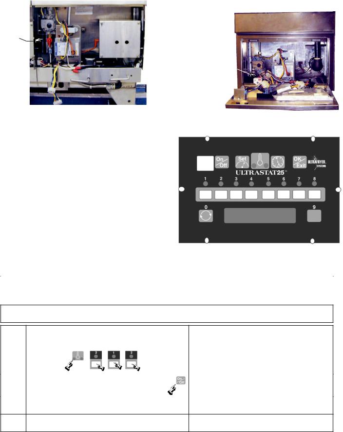
B. TO TEST OPERATE an Ultrafryer Gas Fryer equipped with an Ultrastat 25 Cooking Computer:
PAR-2-F FRYER
1.Ensure the fryer’s power ON/OFF Switch is in the OFF position.
2.Fill the fryer vat with hot or cold water to the middle of the “E<--” in the word LEVEL of the applicable shortening level mark on the rear
of the vat.
3.Turn the MANUAL gas valve to the OFF position and wait FIVE (5) minutes for any accumulation of gas to disperse.
4.ENSURE the MAIN gas shut-off valve is in the ON position, and that the EXHAUST FAN
is ON.
5.Turn the MANUAL GAS VALVE to the ON position.
6.Perform the following steps, in the order listed:

PAR-3-F FRYER
STEP |
ACTION |
RESPONSE |
1 |
Ensure the drain valve lever is in the closed position and |
The AMBER power lamp beside the Fryer Toggle |
that water is at the proper level; then turn the Toggle |
ON/OFF switch will LIGHT. |
|
|
ON/OFF switch to the ON position. |
|
|
|
CAUTION: PRIOR TO PROCEEDING TO STEP 2, VISUALLY CHECK THAT THE HEAT EXCHANGER TUBES ARE COVERED BYAT LEAST 2” (51mm) OF WATER.
|
Turn the computer ON by depressing the computer ON/ |
A. |
BOIL 30:00 will appear in the computer |
|
2 |
OFF key; then place the computer in the BOIL MODE |
|
display. |
|
|
by pressing the computer keys below in that order: |
B. The HEAT DEMAND LED on the computer |
||
|
|
|
and the RED indicator lamp on the |
|
|
|
|
fryer will cycle ON and OFF to heat the water |
|
|
|
|
to 192ºF (89ºC). |
|
3 |
When water begins to BOIL, press the computer |
A. |
The Computer Display will go BLANK. |
|
|
key to exit the Boil Mode. |
|
|
|
4 |
Turn the Fryer Toggle ON/OFF switch to the OFF |
A. |
The AMBER power lamp will turn OFF. |
|
position. |
||||
|
|
|
||
5After the water in the vat and metal surfaces of the fryer has COOLED, drain the water into a floor drain.
11
SHORTENING INSTALLATION
A. LIQUID SHORTENING: the middle line of the E < fryer.
When using liquid shortening (cooking oil) fill the fryer with shortening even with in the word LEVEL of the applicable shortening level mark on the rear wall of the
B.SOLID SHORTENING:
1)Cut a block of solid shortening into small pieces.
2)Place small pieces of solid shortening EVENLY on top of the HEATMECHANISM and THOROUGHLYPACK these pieces of solid shortening between, below and above the HEAT MECHANISM.
While packing solid shortening is messy and time consuming, it is the safest and fastest way to melt solid shortening.
3)Ultrastat 21 equipped Fryer
a)Turn the fryer Toggle ON/OFF switch ON; then place the computer in the SHORTENING MELT MODE by depressing the ON/OFF button. The MELT lamp will LIGHT to indicate the computer is in the SHORTENING MELT MODE; and the HEAT lamp and RED heat mechanism indicator lamp on the fryer will cycle ON and OFF indicating the heat mechanism is periodically being turned ON and OFF to gently heat the shortening.
b)When the heat mechanism is COMPLETELY covered with LIQUID shortening and the shortening is ABOVE the Melt Limit Temperature, replace the grill in the fryer vat; then push the EXIT MELT button on the computer. Proceed to Paragraph B 5) below.
4)Ultrastat 25 equipped Fryer
a)Turn the fryer Toggle ON/OFF switch ON; then place the computer in the SHORTENING MELT MODE by depressing the ON/OFF key. MELT E, G, or P will appear in the computer display indicating the computer is in the SHORTENING MELT MODE; and the HEAT DEMAND LED’S on the computer and the fryer’s RED INDICATOR LAMP will cycle ON and OFF indicating the heat mechanism is periodically being turned ON and OFF to gently heat the shortening.
b)When the heat mechanism is COMPLETELY covered with LIQUID shortening and the shortening is ABOVE the Melt Relaease Temperature, replace the grill in the fryer vat; then push the OK/EXIT key on the computer.
5)Continue adding solid shortening as follows:
a)Place small pieces of solid shortening into a fry basket.
b)CAREFULLY lower the basket into the fryer vat.
c)GENTLY turn the basket to allow these pieces of solid shortening to float away.
d)Repeat the above steps until liquid shortening is even with the middle line of the “ Eß” in the word LEVEL of the applicable shortening level mark on the rear wall of the fryer vat.
WARNING!!! TO AVIOD INJURY
IDO NOT MOVE A FRYER FILLED WITH HOT LIQUID.
IION GAS FRYERS -- DO NOT GO NEAR THE AREA DIRECTLY OVER THE FLUE OUTLET WHEN THE FRYER’S MAIN BURNERS ARE OPERATING.
IIIALWAYS WEAR OIL-PROOF, INSULATED GLOVES WHEN WORKING WITH A FRYER FILLED WITH HOT OIL.
IV ALWAYS DRAIN HOT OIL INTO A METALTUB, POT OR CAN ... HOT OIL CAN MELT PLASTIC BUCKETS OR SHATTER GLASS.
12

INLET GAS LINE SIZING - The Table below is to be utilized to calculate the size (diameter) of the inlet gas line from the building regulator to the fryer manifold.
INLET GAS LINE REQUIREMENTS
PIPE |
|
|
|
|
PIPE DIAMETERS (inches & (mm equivalents)) |
|
|
|
||||
LENGTH |
|
|
|
|
MaximumAllowable Flow (Shown in ft3/hr (M3/hr)) |
|
|
|
||||
|
|
|
|
|
|
|
|
|
|
|
|
|
Feet |
|
1⁄2” |
3⁄4” |
1” |
|
11⁄4” |
11⁄2” |
2” |
|
21⁄2” |
3” |
4” |
(Meters) |
|
(13 mm) |
(19mm) |
(25mm) |
|
(32mm) |
(38mm) |
(51mm) |
|
(64mm) |
(76mm) |
(102mm) |
|
|
|
|
|
|
|
|
|
|
|
|
|
|
|
|
|
|
|
|
|
|
|
|
|
|
15 |
|
62 |
108 |
350 |
|
620 |
960 |
2,000 |
|
3,500 |
5,400 |
11,200 |
(4.6) |
|
(1.7) |
(4.7) |
(9.8) |
|
(17.4) |
(26.9) |
(56.0) |
|
(98.0) |
(151.2) |
(313.6) |
30 |
|
43 |
120 |
245 |
|
430 |
680 |
1,400 |
|
2,450 |
3,800 |
7,900 |
(9.1) |
|
(1.2) |
(3.4) |
(6.9) |
|
(12.0) |
(19.0) |
(39.2) |
|
(68.6) |
(106.4) |
(221.2) |
45 |
|
35 |
98 |
200 |
|
355 |
530 |
1,150 |
|
2,000 |
3,200 |
7,900 |
(13.7) |
|
(1.0) |
(2.7) |
(5.6) |
|
(9.9) |
(14.8) |
(32.2) |
|
(56.0) |
(89.6) |
(182.0) |
60 |
|
30 |
84 |
175 |
|
310 |
480 |
1,000 |
|
1,760 |
2,700 |
5,600 |
(18.3) |
|
(0.8) |
(2.4) |
(4.9) |
|
(8.7) |
(13.4) |
(28.0) |
|
(49.3) |
(75.6) |
(156.8) |
75 |
|
27 |
76 |
155 |
|
275 |
430 |
890 |
|
1,560 |
2,450 |
5,000 |
(22.9) |
|
(0.8) |
(2.1) |
(4.3) |
|
(7.7) |
(12.0) |
(24.9) |
|
(43.7) |
(68.6) |
(140.0) |
90 |
|
25 |
70 |
145 |
|
250 |
395 |
810 |
|
1,430 |
2,260 |
4,550 |
(27.4) |
|
(0.7) |
(2.0) |
(4.1) |
|
(7.0) |
(11.1) |
(22.7) |
|
(40.0) |
(63.3) |
(127.4) |
105 |
|
23 |
64 |
132 |
|
232 |
370 |
(750 |
|
1,300 |
2,100 |
4,200 |
(32.0) |
|
(0.6) |
(1.8) |
(3.7) |
|
(6.5) |
(10.4) |
(21.0) |
|
(36.4) |
(58.8) |
(117.6) |
120 |
|
21 |
60 |
125 |
|
215 |
340 |
700 |
|
1,200 |
1,950 |
4,000 |
(36.6) |
|
(0.6) |
(1.7) |
(3.5) |
|
(6.0) |
(9.5) |
(19.6) |
|
(33.6) |
(54.6) |
(112.0) |
150 |
|
19 |
54 |
110 |
|
195 |
310 |
630 |
|
1,080 |
1,750 |
3,550 |
(45.7) |
|
(0.5) |
(1.5) |
(3.1) |
|
(5.5) |
(8.7) |
(17.6) |
|
(30.2) |
(49.0) |
(99.4) |
180 |
|
17 |
49 |
100 |
|
175 |
280 |
570 |
|
960 |
1,600 |
3,200 |
(54.9) |
|
(0.5) |
(1.4) |
(2.8) |
|
(4.9) |
(7.8) |
(16.0) |
|
(26.9) |
(44.8) |
(89.6) |
210 |
|
16 |
44 |
94 |
|
165 |
260 |
530 |
|
890 |
1,450 |
3,000 |
(64.0) |
|
(0.4) |
(1.2) |
(2.6) |
|
(4.6) |
(7.3) |
(14.8) |
|
(24.9) |
(40.6) |
(84.0) |
240 |
|
15 |
43 |
88 |
|
155 |
240 |
500 |
|
840 |
1,350 |
2,800 |
(73.2) |
|
(0.4) |
(1.2) |
(2.5) |
|
(4.3) |
(6.7) |
(14.0) |
|
(23.5) |
(37.8) |
(78.4) |
270 |
|
14 |
40 |
83 |
|
145 |
230 |
470 |
|
780 |
1,300 |
2,650 |
(82.3) |
|
(0.4) |
(1.1) |
(2.3) |
|
(4.1) |
(6.4) |
(13.2) |
|
(21.8) |
(36.4) |
(74.2) |
300 |
|
14 |
38 |
79 |
|
138 |
215 |
440 |
|
750 |
1,250 |
2,500 |
(91.4) |
|
(0.4) |
(1.1) |
(2.2) |
|
(3.9) |
(6.0) |
(12.3) |
|
(21.0) |
(35.0) |
(70.0) |
450 |
|
11 |
31 |
64 |
|
112 |
176 |
360 |
|
630 |
1,000 |
2,050 |
(137.2) |
|
(0.3) |
(0.9) |
(1.8) |
|
(3.1) |
(4.9) |
(10.1) |
|
(17.6) |
(28.0) |
(57.4) |
600 |
|
10 |
27 |
56 |
|
97 |
152 |
315 |
|
530 |
860 |
1,750 |
(182.9) |
|
(0.3) |
(0.8) |
(1.6) |
|
(2.7) |
(4.3) |
(8.8) |
|
(14.8) |
(24.1) |
(49.0) |
NOTE: 1) |
FT3/HR (M3/HR) values may vary due to heating value and specific gravity of gas supplied by local companies. |
|
|
|||||||||
2) To determine the inlet gas line diameter for the distance between the fryer and mian gas regulator, locate the FT3/HR (M3/HR) of gas required for the
fryer and pipe length and read the pipe diameter on the top row. For example: a bank of fryers containing three (3) Par-2-20 Fryers, one (1) Par-2-18 Fryer and one (1) Par-3-14 fryer operating on Natural gas requires 361.90 FT3/HR (10.24 M3/HR) ((3x71.43 (2.02))+61.90 (1.75)+85.71 (2.43)). If the fryer bank is located 60 feet from the building gas regulator, a 11⁄2” (38mm) diameter gas line MUST be installed between the manifold and regulator.
TABLE 1
INLET GAS LINE SIZING
13
 Loading...