

Page 1
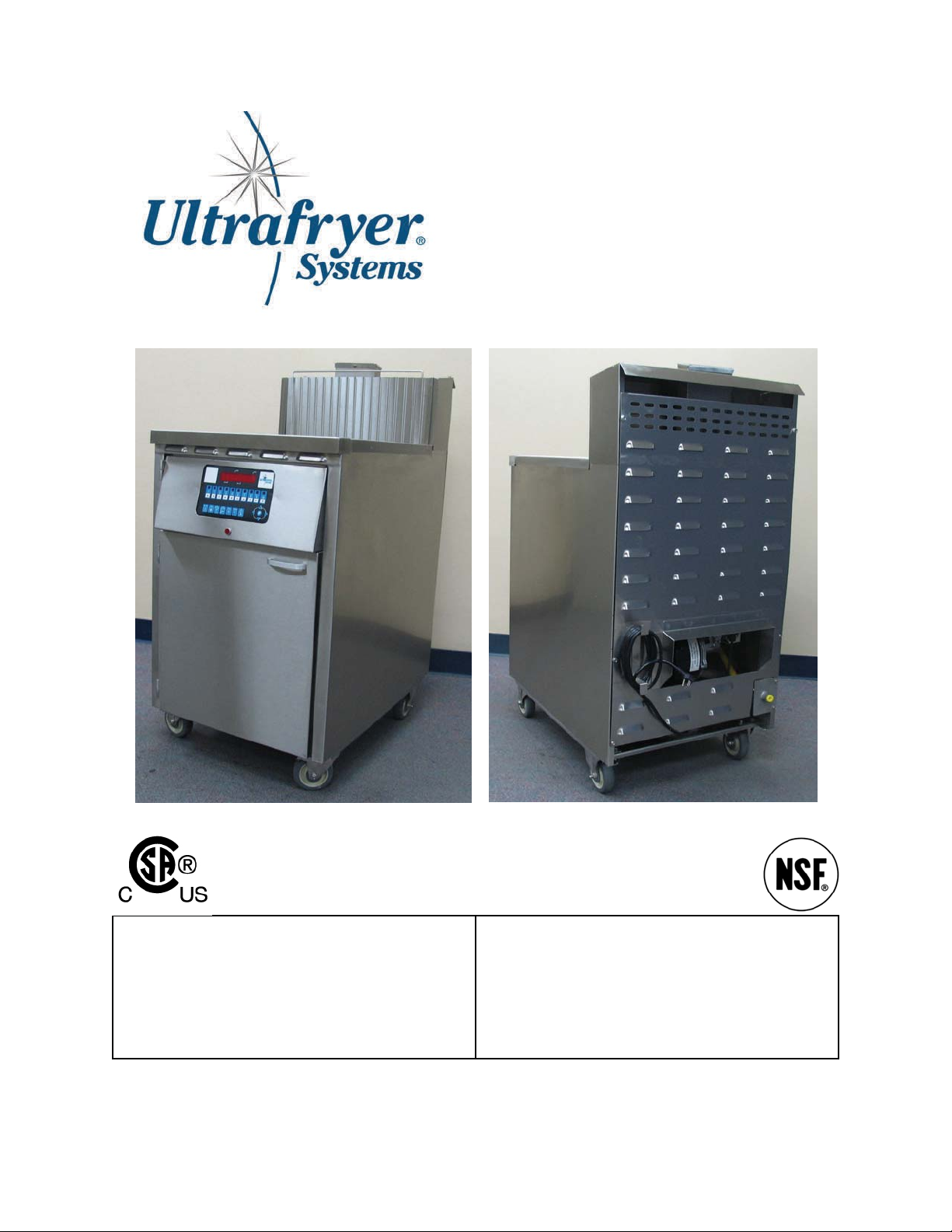
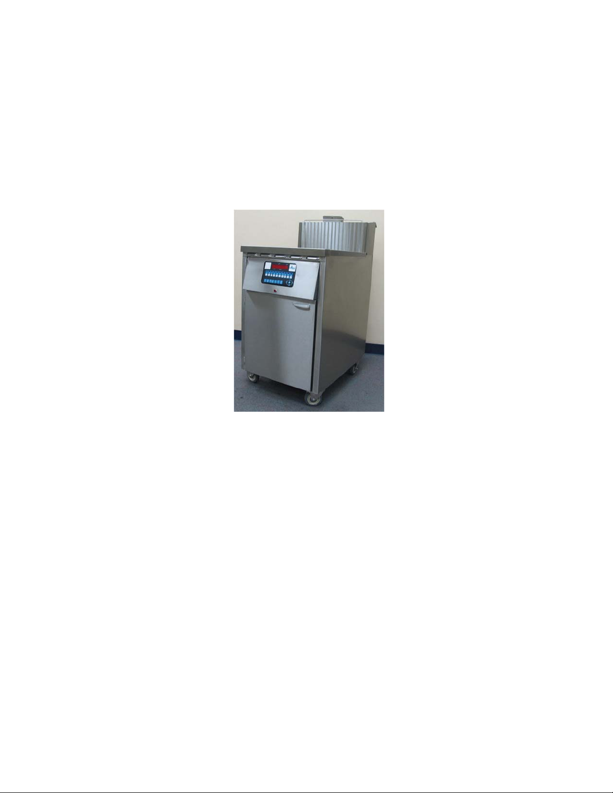
High Performance Series Fryer
Model F-ID-20x17
Operation Instructions
FOR YOUR SAFETY
Do not store or use gasoline or other flammable vapors or
liquids in the vicinity of this or any other appliance.
Purchaser to post in a prominent location instructions to be
followed in the event the user smell gas.
This information shall be obtained by consulting the local gas
supplier.
302 Spencer Lane • P.O. Box 5369 San Antonio, Texas 78201
(800) 525-8130 • (210) 731-5000 • Fax: (210) 731-5099
www.ultrafryer.com
WARNING
Improper installation, adjustment, alteration, service, or
maintenance can cause property damage, injury, or death.
Read the installation, operating, and maintenance instructions
thoroughly before installing or servicing this equipment.
1 30A268 May 2016 Rev A
Page 2

PREFACE
This manual was written and published by the Ultrafryer Systems Engineering Department for use by personnel who
will operate a Model F-ID-20x17 Premix Gas Fryer equipped with an Ultrastat 23 Computer in a commercial cooking
environment. Proper use of a manual will allow store employees to operate, clean, and maintain equipment properly,
thereby reducing service call expenses.
This appliance is intended for professional use and is to be operated by qualified personnel.
The manual is to be retained for future reference.
Throughout this manual, NOTE, NOTICE, WARNING, CAUTION and DANGER are used to alert the operator to items of
special circumstances. These items are identified as follows:
NOTE: Adequate clearances must be provided for servicing and proper operation.
NOTICE: Programming of an Ultrastat 23 Cooking Computer should only be preformed by a store manager or area
supervisor.
WARNING: DISCONNECT THE ELECTRICAL POWER TO THE FRYER.
CAUTION: DO NOT ALLOW ANY CLEANING SOLUTION OR WATER TO SPLASH INTO A VESSEL
OF HOT COOKING OIL, AS IT WILL CONTAMINATE THE OIL AND MAY CAUSE THE
OIL TO SPLATTER, CAUSING SEVERE BURNS.
DANGER: THE FRYER MUST BE CONNECTED TO THE TYPE OF GAS IDENTIFICATION ON THE
RATING PLATE
This manual is intended as a guide for all Model F-ID-20x17 Premix Gas Fryers, regardless of configuration and
2
30A268 May 2016 Rev A
Page 3

TABLE OF CONTENTS
GENERAL INFORMATION
Warranty ............................................................................................................................................ 5
Safety ................................................................................................................................................. 6
Description ......................................................................................................................................... 6
Specifications ..................................................................................................................................... 7
Operating Controls ............................................................................................................................. 7-8
Automatic Safety Features .................................................................................................................. 9
Rating Plate ........................................................................................................................................ 9
Inlet Gas Line Sizing .......................................................................................................................... 9-10
PRE-INSTALLATION
General ............................................................................................................................................... 11
Standards ............................................................................................................................................ 11
Air Supply and Ventilation ................................................................................................................. 11
RECEIVING AND INSTALLING
Unpacking .......................................................................................................................................... 14
Installing ............................................................................................................................................ 14
Leveling ............................................................................................................................................. 14
Gas Connection .................................................................................................................................. 15
Electrical Connection ........................................................................................................................ 15
ULTRASTAT 23
Computer Panel Key Descriptions ...................................................................................................... 16-17
Programming Guide ........................................................................................................................... 18
Start-up and Cooking Operation .......................................................................................................... 19-21
PREVENTIVE MAINTENANCE AND TROUBLESHOOTING
Preventive Maintenance ..................................................................................................................... 23
Troubleshooting .................................................................................................................................. 24
Troubleshooting Chart ........................................................................................................................ 24-25
CLEANING
Daily ................................................................................................................................................... 27
Weekly ............................................................................................................................................... 27
TECHNICAL ASSISTANCE & ORDERING INFORMATION
Technical Assistance .......................................................................................................................... 28
Ordering Information .......................................................................................................................... 28
RECOMMENDED SPARE PARTS
Spare Parts Listing ................................................................................................................................ 31
PARTS IDENTIFICATON
Parts Identification .............................................................................................................................. 33-36
SERVICE PROCEDURE AND ADJUSTMENTS
Harmonic Tone ................................................................................................................................... 38
Gas Valve ........................................................................................................................................... 38
Infrared Burner Spark Ignitor and Temperature Probe Settings.......................................................... 39
Ground Wire Connection .................................................................................................................... 39
Premix Gas Blower (PWM) Settings .................................................................................................. 40
Delay On Make Settings ..................................................................................................................... 40
Temperature Probe Settings ................................................................................................................ 41
Hi Limit Probe Settings ...................................................................................................................... 41
LADDER / SCHEMATIC DIAGRAM
Ladder Diagram .................................................................................................................................. 43
Schematic Diagram............................................................................................................................. 44
3
30A268 May 2016 Rev A
Page 4

GENERAL INFORMATION
4
30A268 May 2016 Rev A
Page 5
A. WARRANTY
5
30A268 May 2016 Rev A
Page 6
B. SAFETY
The major safety concern associated with the Ultrafryer Premix Gas fryer is burns from hot shortening.
In order to prevent serious burns, good housekeeping habits are required. The floor in front of and the area around the fryer
should be kept clean and dry. Whenever anything is placed into a fryer vat, care should be used not to splash the hot shortening.
Product should always be “PLACED” into the shortening, not thrown. Safety goggles, neoprene insulated gloves, and an apron
must be worn while boiling-out a fryer vat. Electrical controls used in the gas fryer operate on 120 volts single phase electrical
power, and no adjustments or replacement of electrical controls should ever be attempted without first disconnecting electrical
power. The fryer should never be operated with wet hands or while standing in water. To do so can result in serious electrical
shock or death.
C. DESCRIPTION
ULTRAFRYER ID 20x17 PREMIX GAS FRYER
The Ultrafryer 20"x17” (508mm x 432mm) ID premix gas fryer was designed by Ultrafryer Systems® to operate as an energyefficient, gas-fired fryer and is design-certified by the Canadian Standards Association (CSA) and the National Sanitation Foundation (NSF). It is manufactured to operate on either NATURAL or PROPANE gas according to the following Operational
Requirements. Each fryer is shipped completely assembled with the accessories packed inside the fryer vat, and each fryer has
been adjusted, tested and inspected prior to shipment. This gas fryer is designed to be used in a commercial food preparation
environment after it is properly installed as outlined in this manual.
6
30A268 May 2016 Rev A
Page 7
D. SPECIFICATIONS
SPECIFICATION ITEM 20”x17” ID
MODEL 20”x17” (508mm x 432mm) ID PREMIX GAS FRYER
OPERATIONAL REQUIREMENTS
Overall Width 21.375” (543mm)
Overall Depth 33.49” (850mm)
Work Height 34.95” (888mm)
Oil Capacity
High Level
Low Level
100 lbs (45.4 liters)
78 lbs (35.8 liters)
Vat Container Size 20.00” x 17.375” (508mm x 441mm)
Gas Pressure (inlet to fryer)
Natural Gas
Propane
Gas Rating
Natural Gas
Propane
7” (178mm) W.C.
14” (356mm) W.C.
150,000 BTU/hr (158.15 MJ/hr)
150,000 BTU/hr (158.15 MJ/hr)
Shipping Cube 29” x 42” x 45” (74mm x 107mm x 114mm)
Shipping Weight 412 lbs (186.9 kgs)
Power Input 120 Volt, 15 Amp, 60Hz, 1 Phase
FT3 / HR (M3 / HR) VALUES May vary due to heating value and specific gravity of gas supplied by local Gas Company
NOTE:
Test Start-Up, Operation, Cooking, Filtering and Boil Out Procedures of a 20”x17” Model ID Premix Gas Fryer in the
manual are based on the Ultrastat 23 Cooking Computer.
Refer to Manual P/N 30A216 to perform these functions in a fryer equipped with this controller.
E. OPERATING CONTROLS
The fryer is equipped with an Ultrastat 23 Cooking Computer as shown on the next page. Operating instructions for the
Ultrastat 23 Cooking Computer (P/N 30A216) will be provided with the fryer. Operating controls on the fryer include the
Ultrastat 23 Cooking Computer and the Red Heating Indicator Lamp, these controls are mounted on the Controller Door. The
Temperature Probe and Hi-Limit Switch, these controls are located inside the vat. The Drain Ball Valve and Red Hi-Limit
Reset Switch, these controls are located behind the Service Access Door. These controls were identified in the illustrations
shown on the next page.
7
30A268 May 2016 Rev A
Page 8
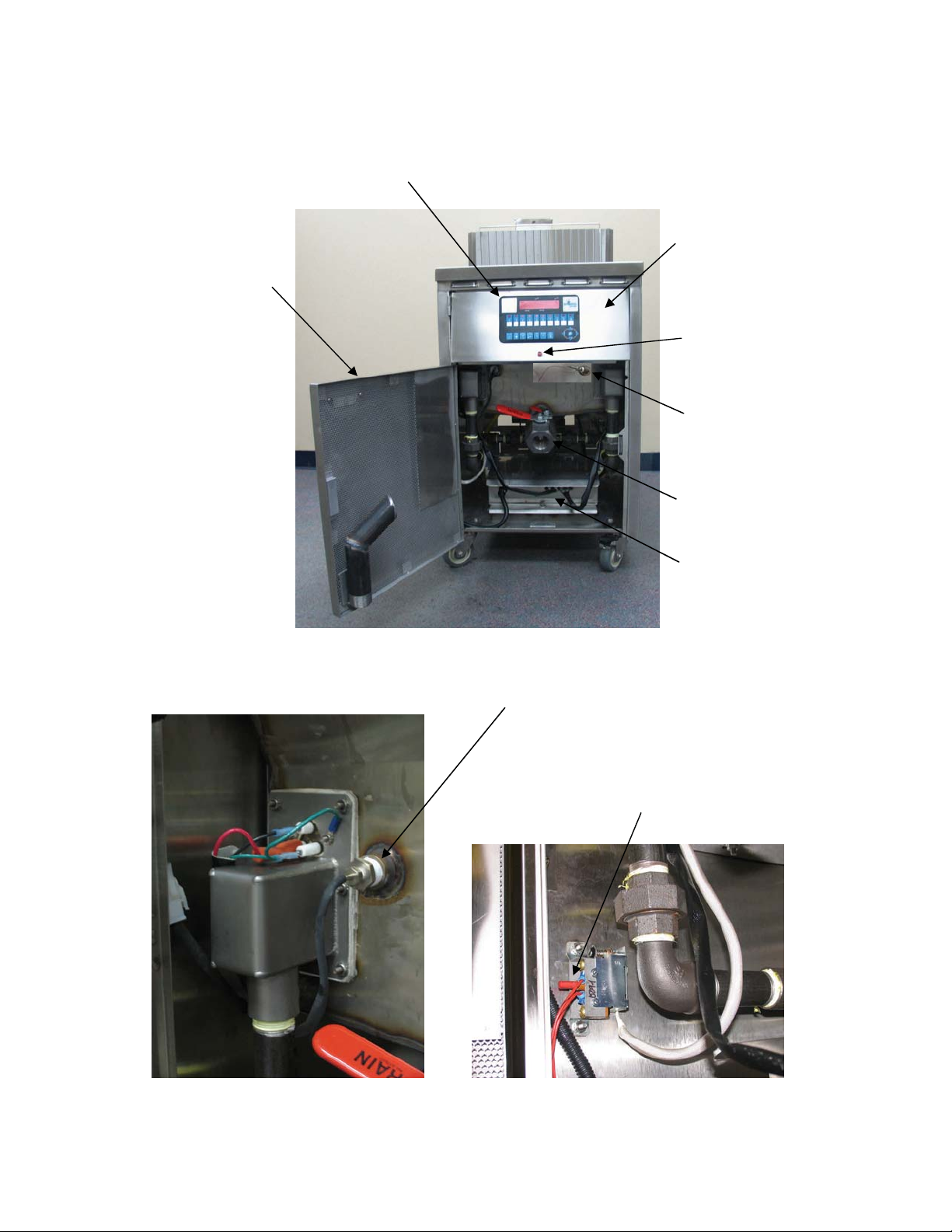
F. OPERATING CONTROLS LOCATION
Ultrastat 23
Cooking Computer
Service Access Door
Controller Door
Red Heating
Indicator Lamp
Hi Limit Probe
Drain Ball Valve
Electrical Control
Box Assembly
Temperature Probe
Hi Limit Reset Switch
8
30A268 May 2016 Rev A
Page 9
G. AUTOMATIC SAFTEY FEATURES
))
(
N
1. High Limit thermostat to shut off gas to the main burners by opening a solenoid –activated safety valve in the
combination gas control valve.
2. Combination gas control valve which includes a built-in pressure regulator.
3. Air pressure switch to open the 24 volt electrical circuit to th e gas control v alve, w hich turns off th e gas to the fryer OFF if a
Blower Motor becomes inoperable.
4. Sensing Circuit within the spark ignitor module to which turns gas to the fryer OFF if a burner FLAME OUT occurs.
5. A Current Sensor and Air Pressure Switch which, combined, provide an air Proof System for the fryer.
H. RATING PLATE
The Rating Plate is located on the inside of the Service Access door and contains the following information: the model and
serial numbers, BTU/HR input rating of the burners, gas manifold pressure in inches W.C. , minimum inlet gas required, and
gas type. This data is essential for proper identification when communicating with ULTRAFRYER SYSTEMS or requesting
special parts or information.
DANGER:
THE FRYER MUST BE CONNECTED ONLY TO THE TYPE OF GAS IDENTIFICATION
ON THE RATING PLATE !
I. INLET GAS LINE SIZING
The table below is to be utilized to calculate the size (diameter) of the inlet gas line from the building regulator to the fryer
manifold.
PIPE
LENGTH
Peet
(Meters) (13 mm) (19mm) (25mm) (32mm) (38mm) (51mm) (64 mm) (76mm) (102mm)
15 62 170 350 620 960 2,000 3,500 5,400 11,200
(4.6) (1.7) (4.7) (9.8) (17.4) (26.9) (56.0) (98.0) (151.2) (313.6)
30 43 120 245 430 680 1,400 2,450 3,800 7,900
(9.1) (1.2) (3.4) (6.9) (12.0) (19.0) (39.2) (68.6) (106.4) (221.2)
45 35 98 200 355 530 1,150 2,000 3,200 7,900
(13.7) (1.0) (2.7) (5.6) (9-9) (14.8) (32.2) (56.0) (89.6) (182.0)
60 30 84 175 310 480 1,000 1,760 2,700 5,600
(18.3) (0.8) (2.4) (4-9) (8.7) (13.4) (28.0) (49.3) (75.6) (156.8)
75 27 76 155 275 430 890 1,560 2,450 5,000
(22.9) (0.8) (2.1) (4.3) (7.7) (12.0) (24.9) (43.7) (68.6) (140.0)
90 25 70 145 250 395 810 1,430 2,260 4,550
(27.4) (0.7) (2.0) (4.1) (7.0) (11.1) (22.7) (40.0) (63.3) (127.4)
105 23 64 132 232 370
(32.0) (0.6) (1.8) (3.7) (6.5) (10.4) (21.0) (36.4) (58.8) (117.6)
120 21 60 125 215 340 700 1,200 1,950 4,000
(36.6) (0.6) (1*7) (3.5) (6.0) (9.5) (19.6) (33.6) (54.6) (112.0)
150 19 54 no 195 310 630 1,080 1,750 3,550
(45.7) (0.5) (1.5) (3.1) (5.5) (8.7) (17.6) (30.2) (49.0) (99.4)
180 17 49 100 175 280 570 960 1,600 3,200
(54.9) (0.5) (1.4) (2.8) (4-9) (7.8) (16.0) (26.9) (44.8) (89.6)
210 16 44 94 165 260 530 890 1,450 3,000
(64.0) (0.4) (1.2) (2.6) (4-6) (7.3) (14.8) (24.9) (40.6) (84.0)
240 15 43 88 155 240 500 840 1,350 2,800
(73.2) (0.4) (1.2) (2.5) (4.3) (6-7) (14.0) (23.5) (37.8) (78.4)
270 14 40 83 145 230 470 780 1,300 2,650
(82.3) (0.4) (1.1) (2.3) (4.1) (6.4) (13.2) (21.8) (36.4) (74.2)
300 14 38 79 138 215 440 750 1,250 2,500
(91.4) (0.4) (1.1) (2.2) (3.9) (6.0) (12.3) (21.0) (35.0) (70.0)
450 11 31 64 112 176 360 630 1,000 2,050
(137.2) (0.3) (0.9) (1.8) (3.1) (4-9) (10.1) (17.6) (28.0) (57.4)
600 10 27 56 97 152 315 530 860 1,750
(182.9) (0.3) (0.8) (1.6) (2.7) (4.3) (8.8) (14.8) (24.1) (49.0)
OTE: 1) FT3/HR (M
2) To determine the inlet gas line diameter for the distance between the fryer and main gas regulator, locate the FT3/HR (M3/HR) of gas required for the fryer and pipe length and read the
pipe diameter on the top row. For example, a 14” PD fryer operating on NATURAL GAS requires 105 FT3/HR (3.0 M3/HR) of gas at the fryer’s inlet gas manifold. If the fryer bank is
located 60 feet from the building gas regulator, a 1” (25mm) diameter gas line MUST be installed between the manifold and regulator.
3
/HR) values may vary due to heating value and specific gravity of gas supplied by local companies.
1/2”
INLET GAS LINE REQUIREMENTS
PIPE DIAMETERS (inches & (mm equivalents
Maximum Allowable Flow (Shown in ft3/hr (M3/hr))
1”
1¼”
1½”
2”
750 1,300 2,100 4,200
2½” 3” 4”
10
30A268 May 2016 Rev A
Page 10
J. FLEXIBLE GAS LINE LENGTHS
The Flexible Gas Line used to connect the gas manifold to the building gas supply line must be rated for the BTU/Hr (MJ/Hr)
designated for the Fryer. Flexible gas lines and their ratings stocked by Ultrafryer Systems are listed below:
FLEXIBLE GAS LINES STOCKED BY ULTRAFRYER SYSTEMS
NUMBER DESCRIPTION
24322
24323
24456
¾“ (19mm) Diameter Flexible Gas Line (w/quick connect couplings)
48” (1219mm) long. Connect-It SSGC75-48-UCQ
1” (25mm) Diameter Flexible Gas Line (w/quick connect couplings) 48”
(1219mm) long. Connect-It SSGC100-48-UCQ
1V” (32mm) Diameter Flexible Gas Line (w/quick connect couplings)
48” (1219mm) long. Connect-It SSGC125-48-UCQ
RATING BTU/HR (MJ/HR)
225,000 (238)
435,000 (459)
875,000 (924)
10
30A268 May 2016 Rev A
Page 11

PRE-INSTALLATION
11
30A268 May 2016 Rev A
Page 12

A. GENERAL:
Safe and satisfactory operation of a Model F-ID 20x17 premix gas fryer depends on its proper installation. Installation must
conform to local codes or, in the absence of local codes, with the current National Fuel Gas Code ANSI Z223.1/NFPA 54
(latest edition). In Canada, gas installation shall be in accordance with the current CSA B 149.1 and .2 installation codes and/or
local codes. Each Model F-ID 20x17 premix gas fryer should be installed as follows:
1. Placed beneath a properly designed exhaust hood
2. Installed by a licensed plumber.
3. Connected to the type gas for which the unit was fabricated as shown on the rating plate.
4. Connected to the proper size pressure regulator installed in the gas supply line and adjusted to the proper manifold
pressure.
5. Connected to the main gas supply line with the proper size supply line.
6. Restrained by use of a restraining device to avoid splashing of hot liquid and to assure tension cannot be placed on the
flexible gas line or fittings. CLEARANCES: The appliance must be kept free and clear of all combustibles. The minimum clearance from combustible and non-combustible construction is 6" (152 mm) from the sides, and 6" (152 mm)
from rear. The fryer may be installed on combustible floors.
NOTE: Adequate clearances must be provided for servicing and proper operation.
B. STANDARDS: Installation must be planned in accordance with all applicable state and local codes, taking into account
the following standards:
1. The fryer and its individual shut-off valve must be disconnected from the gas supply piping system during any pressure
testing of that system at pressures in excess of 1⁄2 psi (3.45kPa). In Canada, gas installation shall be in accordance with the
current CSA B 149.1 and .2 installation codes and/or local codes.
2. The fryer must be isolated from the gas supply piping system by closing its individ ual manual shut- off valve during an y
pressure testing of the gas supply piping system at pressures equal to or less than 1⁄2 psig (3.45kPA).
3. When installed the fryer must be electrically grounded in accordance with local codes, or in the absence of local codes, in
accordance with the current National Electrical code ANSI/NFPA 70 (latest edition). In Canada electrical installation must
be in accordance with the current CSA C22.1 Canadian Electrical Code and/or local codes.
4. Other applicable nationally recognized inst allation s tandards such as:
a. National Fuel Gas Code ANSI Z223.1/NFPA 54 (latest edition)
American Gas Association
1515 Wilson Blvd.
Arlington, VA 22209
b. NFPA Standards #54, #94 and #221 (latest edition)
National Fire Protection Association
470 Atlantic Avenue
Boston, MA 02110
c. ANSI Z21.69/CSA-6.16 AND ANSI Z21.41/CSA 6.9
5. Exhaust vent hood, when installed must conform to the current NFPA 54-1 and Canadian Standards (latest edition).
NOTE: Local building codes will usually not permit a fryer with its open tank of hot oil to be installed immediately next to an
open flame of any type, whether a broiler or an open burner or range. Check local codes before beginning installation.
C. AIR SUPPLY AND VENTILATION: The area around the appliance must be kept clear of any combustible or flammable
products and avoid any obstruction to the flow of ventilation air as well as for ease of maintenance and service. NOTHING
is to be stored in the interior of the fryer’s cabinet.
1. A means must be provided for any commercial, heavy duty-cooking appliance to exhaust combustion wastes outside of
the building. It is essential that a fryer be set under a powered exhaust vent hood or that an exhaust fan be provided in the
wall above the unit, as exhaust temperatures are in the vicinity of 400˚F (204˚C).
NOTE: Strong exhaust fans in a hood or in the overall air conditioning system can produce slight air drafts in the room, which
can interfere with burner performance and be hard to diagnose. Air movement should be checked during installation and if
burner problems persist, make-up air openings or baffles may have to be provided in the room.
2. Exhaust temperature, in addition to the open tank of hot oil, make the storage of anything on shelving over or behind the
fryer unsafe.
3. Filters and drip troughs should be part of any industrial hood, but consult local codes before constructing and installing
any hood.
4. Provisions must be made for an adequate supply of fresh air and adequate clearance must be maintained for air openings
into the combustion chamber.
12
30A268 May 2016 Rev A
Page 13

RECEIVING AND INSTALLING
13
30A268 May 2016 Rev A
Page 14
A. UNPACKING: Check that the container is upright. Use an outward prying motion – DO NOT USE A HAMMER - to
remove the carton. Check the fryer for visible damage; if such damage has occurred do not refuse shipment, but contact the
carrier and file the appropriate freight claims.
B. INSTALLING: Roll the assembled fryer into the building, to its operating location.
WARNING: IMPROPER INSTALLATION, ADJUSTMENT, ALTERATION, SERVICE, OR MAINTENANCE CAN
CAUSE PROPERTY DAMAGE, INJURY, OR DEATH. READ THE INSTALLATION, OPERATING
AND MAINTENANCE INSTRUCTIONS THOROUGHLY BEFORE INSTALLING OR SERVICING
THIS EQUIPMENT.
C. LEVELING:
1. When the fryer is placed in its operating location, check to be sure it is l evel. If not, loosen the cast er s and insert the a pp ro-
priate number of shim plates between leg and caster plates then retighten the caster bolts.
2. If the floor is smooth and level, adjust to the high corner and measure with a spirit level. If the floor is uneven or has a
decided slope, level the unit with metal shims.
NOTE: A caster may not return exactly to the same position after being moved, which may require re-leveling after each move.
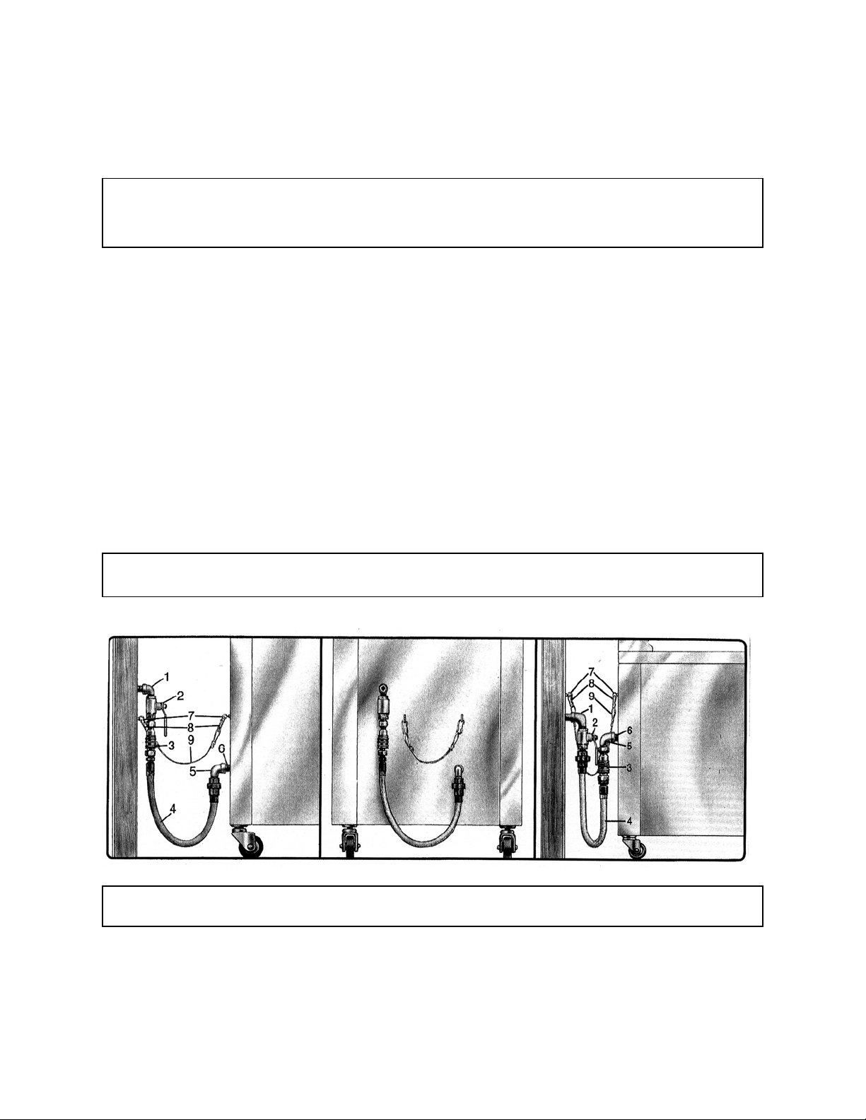
3. Connect the gas manifold to the building gas supply line by means of a CSA Group APPROVED flexible gas line as
shown in the figure below.
NOTE: CONNECT-IT Inc. 3⁄4" (19mm), 1" (25mm) and 1 1⁄4" (32mm) flexible gas hose 4 feet long (1219mm) with a quick
disconnect coupling on one end is available from Ultrafryer Systems under PN 24322 (3⁄4" (19mm) hose), PN 24323
(1" (25mm) hose) and PN 24456 (1 1⁄4" (32mm) hose). These hoses are equipped with a fusible link, which melts at
361°F (183ºC) that will SHUT OFF the gas supply when it melts. Reference Installation Instructions sheet provided
with hose for additional information. A 44" (1119mm) long restraining device is also available under PN 24324. Install
as shown below between the wall and the fryer using existing mounted hardware or add hardware to the wall and fryer
making a secure connection at each ends.
CAUTION: THE BUILDING GAS SUPPLY LINE MUST BE SIZED TO PROVIDE THE VOLUME OF GAS
REQUIRED FOR PROPER OPERATION AS EXPLAINED ON THE PREVIOUS PAGE.
TYPICAL GAS CONNECTION
1. BUILDING GAS SERVICE LINE 6. APPLIANCE MANIFOLD/
WARNING: THE RESTRAINT DEVICE (ITEM 9) MUST BE INSTALLED TO ASSURE TENSION CANNOT BE
PLACED ON THE FLEXIBLE GAS LINE OR FITTING.
NIPPLE
2. MAIN GAS CUT-OFF VALVE 7. EYELET FASTENERS
3. CONNECT-IT QUICK-DISCONNECT 8. SPRING HOOK
4. FLEX-CON CONNECTOR 9. RESTRAINING CHAIN
5. ELBOW
14
30A268 May 2016 Rev A
Page 15

D. GAS CONNECTION: The gas supply (service) line must be the same size or greater than the inlet line of the appliance.
THE GAS SUPPLY LINES MUST BE SIZED TO ACCOMMODATE ALL THE GAS FIRED EQUIPMENT
THAT MAY BE CONNECTED TO THAT SUPPLY. Refer to the Inlet Gas Line Sizing Table and inlet gas require-
ments.
NOTE: Sealant used on all pipe joints must be resistive to natural and propane gas.
1. Manual shut off valve: This supplier-installed valve must be installed in the gas service line ahead of the appliance and in
a position where it can be reached quickly in the event of an emergency.
2. Pressure regulator: All commercial cooking equipment must have a pressure regulator on the incoming service line for
safe and efficient operation, because service pressure may fluctuate with local demand. External regulators are not required on this fryer, as that function is performed by a combination gas control valve, however if the incoming pressure is
in excess of 1⁄2 psig, a step-down regulator will be required.
3. Natural gas: Natural gas fryers require 7” (178mm) water column (W.C.) “inlet” pressure to the fryer’s combination gas
control valve for proper operation, when all gas units are operating simultaneously. Propane gas fryers require
14" (356 mm) water column (W.C.) “inlet” pressure to the fryer’s combination gas control valve for proper operation,
when all gas units are operating simultaneously. This “inlet” pressure MUST be checked with a manometer PRIOR to
WARNING: IF THE “INLET” GAS PRESSURE AT THE FRYER’S COMBINATION GAS CONTROL VALVE
“EXCEEDS” 1⁄2 lb/in2 (.035 kg/cm2) OR APPROXIMATELY 11” (280mm) W.C., AN EXTERNAL
REGULATOR MAY BE NEEDED TO PREVENT DAMAGE TO THE COMBINATION GAS VALVE
AND VOIDING OF WARRANTY. FAILURE TO ADDRESS THIS COULD RESULT IN AN EXPLOSION OR A FIRE.
placing the fryer in operation.
4. Combination gas control valve: The correct combination gas control valve and orifice is installed at the factory for
NATURAL and PROPANE units based on each Purchase Order. This valve should be CHECKED/ADJUSTED by
qualified service personnel using proper test equipment for the following “OUTLET” gas pressure PRIOR to start-up of
a fryer. NATURAL GAS FRYERS 7" (178mm) W.C. PROPANE FRYERS 14" (356mm) W.C.
5. Rigid connections: Check any installer-supplied intake pipe(s) visually and/or blow them out with compressed air to clear
dirt particles, threading chips or any other foreign matter before connecting to the service line as these particles may clog
the orifice when gas pressure is applied. All connections must be tested with a soapy solution before lighting the fryer.
DO NOT USE AN OPEN FLAME TO CHECK FOR LEAKS! Putting an open flame beside a new connection is not
only dangerous, but will often miss small leaks that a soapy solution would find.
6. Flexible Couplings and Connectors: The installation is to be made with a connector that (1) complies with the Standard
for Connectors for Movable Gas Appliances, ANSI Z21.69 (CSA 6.16), and a quick-disconnect device that complies
with the Standard for Quick-Disconnect Devices for Use With Gas Fuel, ANSI Z21.41 (CSA 6.9) (2) adequate means
must be provided to limit the movement of the appliance without depending on the connector and the quick dis- connect
device or its associated piping to limit the appliance movement and (3) the location(s) where the restraining means may
be attached to the appliance shall be specified. DOMESTIC CONNECTORS ARE NOT SUITABLE!!!
7. Fryer Service: The fryer is equipped with swivel casters. To service th e fr yer:
a) Remove / unplug power supply from fryer
b) Turn “OFF” gas supply at the supply source.
b) Disconnect the flexible gas line quick-disconnect
c) Disconnect restraint means and roll fryer out for rear service access.
d) When the fryer is re-positioned, be sure to reconnect the restraint and level the fryer.
E. ELECTRICAL CONNECTION: The MAXIMUM current draw per vat at Initial Start-up or during a Warm-up Cycle will
be 3 Amperes at 120 Volts. When running the Filter System simultaneously allow for an additional 3 Amperes. Refer to the
wiring diagram attached to the inside of the Service Access door for internal electrical connections.
WARNING: (ELECTRICAL GROUNDING INSTRUCTIONS)
THIS APPLIANCE IS EQUIPPED WITH A THREE-PRONG (GROUNDING) PLUG FOR YOUR PROTECTION
AGAINST SHOCK HAZARD AND SHOULD BE PLUGGED DIRECTLY INTO A PROPERLY GROUNDED
THREE-PRONG RECEPTACLE. DO NOT CUT, REMOVE, OR OTHERWISE BYPASS THE GROUNDING
PRONG ON THIS PLUG!
15
30A268 May 2016 Rev A
Page 16

F. Ultrastat 23 Cooking Computer
The Ultrastat 23 Cooking Computer is a high performance, microprocessor-based electronic controller designed for use in
commercial appliance temperature and timing control applications. Utilizing a microcontroller board, membrane switch front
panel with a digital LED readout and display board, the Ultrastat 23 Cooking Computer has been customized for Ultrafryer
Systems applications by the addition of up to 10 stage cooking profiles for each of the 10 product keys; features can be
programmed to cook products under “Flex” or “Straight” timing modes. Operation of the Ultrastat 23 Cooking Computer is
covered in its Instruction Manual PN 30A216 provided with the Fryer.
1 2 3 4 5
15 14
6 8 9 10
11 12
13
7
16
30A268 May 2016 Rev A
Page 17

COMPUTER PANEL KEY DESCRIPTIONS
1. HOLD LAMP
When lit (bright) indicates a product hold time is being tracked.
2. HEAT LAMP
When lit (bright) indicates the computer is calling for heat.
3. DISPLAY
Displays modes, functions and operations of the computer.
4. MELT LAMP
When lit (bright) indicates the computer is in the melt cycle.
5. PROGRAM LAMP
When lit (bright) indicates the computer is in the program mode.
6. ON/OFF KEY
Turns the computer ON and OFF when the fryer power switch is in the ON position and the drain valve lever is in the
closed UP position.
7. PROGRAM KEY
a. In “operating” mode, allows access to the programming mode.
b. In “programming” mode, allows access to the operating mode and general navigation function.
8. SCAN KEY
a. In “operating” mode, displays the remaining cook time on every product currently in a cook cycle and lights the re-
spective products “LED” for 2 seconds.
b. In “programming” mode, steps to the next function to be programmed.
9. ENTER EXIT FILTER KEY
This key will force the fryer into the filter mode. This key is an optional feature.
10. TEMP/TOGGLE CLEAR KEY
a. In “operating” mode, displays the actual temperature followed by the programmed “set” tem perature.
b. In “programming” mode, will “clear” values from a data field.
11. HOLD KEY
a. In “operating” mode, used to view remaining hold times.
12. SET BACK
a. In operating mode forces setback . Display will show “setback” and appliance will be controlled to setback tempera-
ture instead of set point temperature.
13. EXIT/MELT KEY
a. In “operating” mode, used to manually exit the shortening melt cycle.
14. PRODUCT LED
a. When lit (bright) in the “operating” mode, identifies the product data being displayed.
b. When lit (bright) in the “programming” mode, identifies the product being programmed.
15. PROGRAMMING AND PRODUCT COOK KEY
a. In “operating” mode, used to start and stop a product’s cook cycle.
b. In “programming” mode, used to enter numerical values 1 to 10.
17
30A268 May 2016 Rev A
Page 18

y
Ultrastat 23 Programming Guide
Turn Toggle ON/OFF switch to ON position and
amber power indicator lamp will illuminate.
Then press power ON/OFF key.
Push and hold the "P" key for 3 seconds to enter PROGRAMMING MODE.
PROGRAM will appear in display.
Push “P" key the second time to display CODE. Enter
“1724" and push the "P" key. RECIPE will display.
Push °P" key and “PRODUCT” will
display. Hit product key you want to
Display shows ‘‘ALL”. Push “P” key to program
each function and "NAME" appears. To change
hit the “DOWN ARROW’ and scroll to find the
word you want in the library. Then push the “P”
ke
to enter it and go to the next item.
'TIME 1" will display. To change the time hit "TOGGLE CLEAR”
index the time you want on the number pad and press the “P*
"
"
"TEMP 1" will display. To change hit “TOGGLE CLEAR”
and key in the amount you v/ant and hit the “P” key.
"FLEX" or "STRAIGHT'1 time will appear. To change from one to
the other, hit the left arrow key. Then hit the “P" key to save it.
Display shows “TIME 2". Repeat steps 6, 7, and 8 for
each profile. After the last profile, display will show
“
To change "ALARM TIME 1" hit “TOGGLE CLEAR" and
index what you want on the number keys and hit the “P”
To change “ALARM NAME” hit “DOWN ARROW’ and
scroll until you find the name you want. Then hit the “P"
Display will show “HOLD TIME 1”. For most applications this
is not used so exit at this point. To exit press the “DOWN
ARROW' key repeatedly until "EXIT'' shows on the display.
Then hit the "P" key. “PRC DUCT" will show on the display.
Then hit the “UP ARROW* key and display will show “EXIT".
Hit the “P" key and display shows “RECIPE”. Hit the "UP
ARROW again then hit "P” key and "PREHEAT'* or “READY”
should appear. You are now out of program mode and ready
to operate with the latest changes.
"
"
”
18
30A268 May 2016 Rev A
Page 19

ULTRASTAT 23 START-UP AND COOKING COMPUTER OPERATION
NOTICE:
1) The computer will keep the fryer in the MELT CYCLE until the EXIT MELT button is manually depressed.
2) The computer CANNOT be taken out of the SHORTENING MELT MODE until the shortening temperature
reaches the MELT LIMIT TEMPERATURE. The Melt Limit Temperature is factory set for a HIGH exit
temperature (135˚F / 57˚C) or a LOW exit temperature (100º F/38ºC).
The following are abbreviated operating procedures for a fryer equipped with an Ultrastat 23 Cooking Computer. The attached
Ultrastat 23 Ultrafryer Computer Operating Instructions, Manual PN 30A216, contains DETAILED Operating, Filtering, BoilOut, and Programming Instructions.
START-UP and COOKING
ULTRASTAT 23 START-UP - Safely start-up an gas fryer equipped with an Ultrastat 23 Cooking computer as follows:
STEP ACTION RESPONSE
1 ENSURE the drain valve lever on the fryer
is in the CLOSED position, shortening is at
A. The fryer heat exchanger will power up and begin to heat the
shortening.
the proper level, then turn the computer ON
by depressing the computer ON/OFF
button.
CAUTION:
PRIOR TO PROCEEDING TO NEXT STEP, VISUALLY CHECK THAT THE HEAT
EXCHANGER IS COVERED WITH AT LEAST 2” (51mm) OF SHORTENING
2 Turn the Computer ON by depressing the
computer ON/OFF button.
3 Once the Melt Limit Temperature is
reached depress the EXIT MELT BUTTON on the computer to cancel the
SHORTENING MELT MODE.
4 When “READY” appears in the Computer
display indicating the SET-POINT TEMPERATURE of the shortening has been
reached, a COOK cycle can be initiated.
ULTRASTAT 23 COOKING COMPUTER PROGRAMMING
Program the Ultrastat 23 Cooking Computer according to the Computer Operating Instructions Manual
(PN 30A216) provided with the Fryer.
Programming of an Ultrastat 23 Cooking Computer should only be preformed by a store manager or
area supervisor.
A. The MELT lamp will LIGHT to indicate the computer is in
the SHORTENING MELT MODE.
B. The HEAT lamp on the computer and the RED heat mechanism
indicator lamp on the fryer will cycle ON and OFF indicating
the heat mechanism is periodically being turned ON and OFF to
gen- tly heat the shortening.
A. “HEATING” will appear in the computer display indicating
shortening temperature is more than 10˚F (5˚C) below the setpoint temperature.
B. The HEAT lamp on the computer and the RED heat mechanism
indicator lamp will remain ON until the set-point temperature is
reached.
A. Stir the shortening several times to ensure that all the shortening
has reached the set point temperature.
NOTICE:
19
30A268 May 2016 Rev A
Page 20

GENERAL COOKING
Most products should be cooked with a shortening temperature about 350˚F (177˚C); however, each product should be
cooked at the LOWEST temperature that produces a high quality product while obtaining maximum usage of the shortening.
WARNING:
I – DO USE A HIGH QUALITY SHORTENING TO ACHIEVE A CONSISTENT
QUALITY PRODUCT AND LONG TERM SAVINGS
II – DO NOT SALT PRODUCTS OVER THE FRYER AS SALT QUICKLY DETERIORATES
THE SHORTEN ING AND FLAVORS OTHER PRODUCTS COOKED IN THE SAME
SHORTENING
III – DO FILTER SHORTENING AFTER THE LUNCH AND DINNER RUSH AND MORE OF-
TEN IN A HIGH SALE VOLUME STORE; AND BOIL-OUT THE FRYER EVERY 7 DAYS
NOTICE:
Startup steps 1, 2, 3, and 4 will have to be repeated each time any of the following occurs:
DRAIN VALVE IS OPEN. FRYER ON/OFF SWITCH IS TURNED OFF TO FILTER
SHORTENING OR BOIL-OUT A FRYER. FRYER ON/OFF SWITCH IS TURNED OFF AT
CLOSING OR ANY OTHER REASON.
POWER FAILURE
This fryer cannot be operated during power failures. DO NOT attempt to bypass safety and manually operate fryer.
CAUTION:
THE FRYER HAS A RESTRAINT ATTACHED TO THE WALL TO LIMIT MOVEMENT AND
TIPPING IN ORDER TO AVOID SPLASHING OF HOT LIQUID.
MOVING THE FRYER WITH HOT COOKING OIL IN THE VESSEL MAY CAUSE SPLASHING OF
THE HOT LIQUID CAUSING SEVERE BURNS.
IF MOVING THE FRYER IS REQUIRED FOR CLEANING OR SERVICING.
TAKE THE REQUIRED STEPS OF REMOVING THE RESTRAINT, POWER AND GAS
CONNECTIONS BEFORE MOVING THE FRYER AND MAKE SURE THE COOKING OIL IN THE
VESSEL IS COLD OR HAS BEEN REMOVED FROM THE VESSEL TO LIMIT ACCIDENTAL
BURNS OR DAMAGE TO THE FRYER.
20
30A268 May 2016 Rev A
Page 21

When the Computer is taken out of the SHORTENING MELT MODE each morning, shortening in the fryer vat will be
heated to its SETPOINT temperature, “HEATING” will appear in the display to indicate the shortening temperature is
MORE than 20˚F (-6.6˚C) BELOW the set point temperature. When shortening temperature rises to the SETPOINT temperature, “READY” will appear in the display indicating a COOK CYCLE can be started.
STARTING A COOK CYCLE
To start a cook cycle simply press the product key for the product you wish to cook. Cooking time will be displayed
“3:00” (example) and this time will immediately start to count down in minutes and seconds. It will count down to “ :00”
followed by a beeping signal. To turn this signal OFF and reset the Computer, press the same product key used to start the
COOK CYCLE.
CANCELLING A COOK CYCLE
If a cook cycle was inadvertently started it may be cancelled two (2) ways:
1) Press and hold the same product key used to start the cook cycle for 4 SECONDS. This prevents an accidental start of a
cook cycle while a product is being cooked.
2) A cook cycle can be CANCELLED at any time by turning the fryer ON/OFF Switch to the OFF position.
Press and Hold
Product Key
ON/OFF Switch
21
30A268 May 2016 Rev A
Page 22

PREVENTIVE MAINTENANCE AND TROUBLESHOOTING
22
30A268 May2016 Rev A
Page 23

PREVENTIVE MAINTENANCE
Minimal maintenance is required on the fryer because of its design and materials used in the manufacturing process.
However some preventive maintenance and inspection must be performed periodically to prevent breakdowns which could
curtail food sales. Any preventive maintenance or inspection should be accomplished with CAUTION while the fryer is in
operation since HOT liquid shortening could cause severe burns. If service or repairs are required, all electrical power and gas
MUST BE TURNED OFF PRIOR TO preforming that service or repair.
PREVENTIVE MAINTENANCE SCHEDULE
DAILY
ITEM INSPECT FOR
Grease Filters Clean grease filters in the exhaust vent hood every evening and
allow them to dry overnight.
WEEKLY
ITEM INSPECT FOR
Drain Valve Handle Determine if the Drain Valve Handle is securely attached to the
drain valve and that the valve can be easily opened and closed.
Temperature Sensing Probes During boil-out of the fryer, inspect the temperature and hi limit
sensing probes for any visible damage.
23
30A268 May2016 Rev A
Page 24

TROUBLESHOOTING
A. GENERAL: The problems and possible solutions listed in the troubleshooting chart below are typical problems that are
frequently encountered. ONLY qualified repairmen are to use the troubleshooting chart to repair this fryer. In the event a main
burner malfunction occurs, perform the following checks PRIOR to contacting a repairman:
1. Check that the fryer electrical plug is connected to an electrical receptacle.
2. Ensure the applicable Circuit Breaker is in the ON position and that the fryer ON/OFF switch is in the ON position.
3. Ensure the applicable fryer control has been placed in the EXIT MELT mode.
4. Ensure the gas supply line quick-disconnect coupling is SEATED on the gas manifold fitting.
5. Determine that the blower is operating.
B. TROUBLESHOOTING CHART: Should a problem occur that cannot be corrected after performing the above CHECKS,
contact an AUTHORIZED repairman and/or Ultrafryer Systems Customer Service 1-800-525-8130 and provide the information acquired while performing these checks.
ITEM PROBLEMS POSSIBLE SOLUTIONS
1 Ignition Lockout 1.) Harness connection to gas valve
2.) Gas valve or gas pressure
3.) All harness connections
4.) Electrode
5.) Interconnecting wiring malfunction
6.) Ignition module malfunction
8.) Grounding Status
2 No spark, No blower 1.) Harness connections
2.) Probe lead wires
3.) Open probe
4.) Controller
3 “Puffing” during normal start up 1.) Incorrect gas pressure
2.) Cracked electrode
3.) Electrode gap exceeded
4 Burner lights but will not maintain flame 1.) Igniter / flame sense misalignment
2.) Insufficient gas pressure
5 Excessive Heat 1.) Incorrect temperature offset selected
2.) Set Temperature exceeding 400 deg F
3.) Temperature probe malfunction
4.) Cooking control malfunction
5.) Interface board malfunction
6.) Gas pressure incorrect
6 Low heat 1.) Incorrect temperature offset selected
2.) Cooking control malfunction
3.) Temperature probe malfunction
4.) High limit tripped
5.) Interface board malfunction
6.) Gas pressure incorrect
7 Intermittent problems 1.) High ambient temperatures
2.) Wiring connections loose
8 No power to cooking control,
fryer does not heat
1.) Should display “OFF” when powered
2.) Main circuit breaker off
3.)Transformer inoperative
4.) Interconnecting wiring malfunction
24
30A268 May2016 Rev A
Page 25

TROUBLESHOOTING CHART CONTINUED:
Should a problem occur that cannot be corrected after performing the above CHECKS, contact an AUTHORIZED repairman
and/or Ultrafryer Systems Customer Service 1-800-525-8130 and provide the information acquired while performing these
checks.
ITEM PROBLEMS POSSIBLE SOLUTIONS
9 High limit thermostat shutting down sys-
tem
10 Excessive time to melt shortening 1.) Melt cycle timing incorrect
11 Dry fire fry tank 1.) No shortening in vat
1.) Shortening level below minimum fill line
2.) Probe malfunction
3.) Controller malfunction
2.) Insufficient gas pressure
3.) Probe malfunction
4.) Control malfunction
2.) Control malfunction
3.) Probe malfunction
CAUTION: ENSURE REPAIRMEN ARE ADVISED THAT FRYER RESTRAINTS MUST BE DISCONNECTED/
RECONNECTED. IF A FRYER IS TO BE MOVED DURING MAINTENANCE OR REPAIR, AND
THAT ELECTRICAL POWER AND GAS MUST BE TURNED OFF PRIOR TO PERFORMING ANY
MAINTENANCE OR REPAIR.
25
30A268 May2016 Rev A
Page 26

CLEANING
26
30A268 May 2016 Rev A
Page 27

GENERAL CLEANING
Any item of equipment operates and lasts longer when kept clean and properly maintained, and the Ultrafryer is no exception.
In order for this fryer to provide years of trouble-free service, it must be CLEANED and MAINTAINED according to the
instructions listed below.
DAILY
1) Clean the fryer surfaces periodically during operating hours with a solution of sanitizer and hot water, and at closing with
stainless steel cleaner. If necessary, use a dampened type 7447 RED or 7440 BROWN (heavy duty) Scotch brite pad to
remove encrusted material. DO NOT use steel wool, abrasive cloths, cleaners, powders, metal knife, spatula or any metal
object to scrape stainless steel! Scratches on stainless steel are almost impossible to remove.
2) Filter the shortening in each fryer once a day or according to Company Policy.
CAUTION:
DO NOT ALLOW ANY CLEANING SOLUTION / WATER TO SPLASH INTO THE VESSEL OF HOT COOKING
OIL AS IT WILL CONTAMINATE THE OIL AND MAY CAUSE THE OIL TO SPLATTER, CAUSING SEVERE
BURNS
WEEKLY
1) BOIL-OUT the fryer vat using Boil Out Compound according to procedures in the cleaning manual provided by the
chemical provider.
2) Perform steps 1 and 2 listed above under the Daily Cleaning.
27
30A268 May 2016 Rev A
Page 28

TECHNICAL ASSISTANCE, ORDERING INFORMATION
28
30A268 May 2016 Rev A
Page 29

A. TECHNICAL ASSISTANCE - Contact an authorized service agent or the Customer Service Department,
Ultrafryer Systems at 1-800-525-8130 for technical assistance.
E-Mail technical assistance at: techserv@ultrafryer.com
B. ORDERING INFORMATION:
1. REPLACEMENT PARTS - Provide the following information when ordering replacement parts by phone, fax or mail:
Your company name and phone number
Your company purchase order number
Bill-to address
Ship-to address
Quantity desired
Part number and description of the desired-item Your name or signature of authorized-buyer
Phone in order to: 1-800-525-8130
FAX order to: 1-210-731-5061
Mail order to: Ultrafryer Systems
Order Entry Office
P.O. Box 5369
San Antonio, TX 78201
E-Mail your order to: custserv@ultrafryer.com
2. TERMS - Net 30 days for customers on approved accounts. Past due balances will be charged 1% per month (12% per an-
num) until full balance is paid.
3. DAMAGES - Ultrafryer Systems is not responsible for damage occurring in transit. All deliveries must be inspected for
damage to shipping containers prior to departure of the delivering carrier. Any damage must be notated on the receiving document to facilitate filing of freight claims. Carriers must be notified immediately and freight inspections must be requested
from the carrier. Ultrafryer Systems can and will gladly assist you in preparing and processing of the necessary claims only if
proper notification has been accomplished on the carrier delivery document. Damaged equipment and or containers must be
available for the claims inspector to inspect.
4. RETURNS - Ultrafryer Systems cannot guarantee credit for items returned without proper authorization. All returns must
have prior Ultrafryer Systems Customer Service or Warranty department approval. An assigned number will be issued by the
approval authority. Please print the assigned number on all returned packages and corresponding paperwork. Returned goods
are subject to a l5% restocking charge. Ultrafryer Systems is not responsible for freight charges on returned goods unless
authorized by Customer Service and or Warranty personnel. Ultrafryer Systems does not receive freight collect or C.O.D.
shipments.
28
30A268 May 2016 Rev A
Page 30

RECOMMENDED SPARE PARTS
30
30A268 May 2016 Rev A
Page 31

A. RECOMMENDED SPARE PARTS
To minimize downtime on the premix gas fryer upon failure of a component part, at least one (1) of the following items should
be kept as a spare part in a local area:
PREMIX GAS FRYER
RECOMMENDED SPARE PARTS LISTING
DESCRIPTION PN
Computer, Cook U23 22A651
Blower Premix 5.0 Power Burner and Gas Valve 17A031
Gasket, Blower Motor / Manifold IDE 22A810
Burner Infrared 1x3x8 W/ Mounting Plate 22A807
Rod, Ignitor Infrared Burner F/ 22A807 18610
Gasket, Mount Infrared Burner IDE 20in 22A811
Module, Ignitor Spark Dual Infrared 18A384
Transformer, Step Down 110V to 24V
18180
Transformer, FAST Wiring Harness 18A047
Relay, 24V DC 10 AMP SPDT Computer 23A023
Relay, 24V AC Flange Mounted 18A034
Relay, 24V AC DELAY ON MAKE 18A102
Control, 24VAC Universal Gas Blower (PWM) 23A462
Switch, Air Pressure 18A291
Switch, HI Limit 19B782
Probe, Temp Thermistor 18A006
Snap Light, Red Neon 125V 1/3 Watt 23043
31
30A268 May 2016 Rev A
Page 32

PARTS IDENTIFICATION
32
30A268 May 2016 Rev A
Page 33

MODEL F-ID-20X17 PREMIX GAS FRYER
CONTROL PANEL
1
2
ITEM DESCRIPTION PN
1
Computer, Cook U23 22A651
2
Snap Light, Red Neon 125V 1/3 Watt 23043
33
30A268 May 2016 Rev A
Page 34

MODEL F-ID-20X17 PREMIX GAS FRYER
FRONT VIEW
123
10
4
5
6
7
8
4
5
6
7
8
9
ITEM DESCRIPTION PN
1
Probe, Temp Thermistor 18A006
2
Fitting, Compression Male 3/8 NPT 24A270
3
Switch, HI Limit 19B782
4
Box Mount, Infrared Burner 19C991
5
Burner Infrared 1x3x8 W/ Mounting Plate 22A807
6 Rod, Ignitor Infrared Burner
7
Gasket, Blower / Box IDE 22A803
8 Baffle, Agitator 20in IDE Front
9 Valve, Ball 1 1/2in Full W/ Lock Mech
10
Box, Assy IDE Electrical Control 12D111
34
30A268 May 2016 Rev A
22A807
19C993
24A204
Page 35

MODEL F-ID-20X17 PREMIX GAS FRYER
REAR VIEW
1
2
3
4
5
6
ITEM DESCRIPTION PN
1
Box, W/ Flue F/ 20in IDE 19C992
2
Gasket, Blower / Box IDE 20in 22A803
3
Baffle, Agaitor 20in IDE Rear 19C994
4
Blower, Premix 5.0 Power Burner and Gas Valve 17A031
5
Gasket, Blower Motor / Manifold IDE 22A810
6 Switch, Air Pressure
18A291
35
30A268 May 2016 Rev A
Page 36

BOX ASSEMBLY, IDE ELECTRICAL CONTROL
5
1
2
3
4
7
ITEM DESCRIPTION PN
6
1
Control, 24VAC Universal Gas Blower (PWM) 23A462
2
Relay, 24V AC Flange Mounted 18A034
3
Relay, 24V DC 10 AMP SPDT Computer 23A023
4
Relay, 24V AC DELAY ON MAKE 18A102
5
Transformer, FAST Wiring Harness 18A047
6 Module, Ignitor Spark Dual Infrared
7
Transformer, Step Down 110V to 24V 18180
18A384
36
30A268 May 2016 Rev A
Page 37

SERVICE PROCEDURES AND ADJUSTMENTS
37
30A268 May 2016 Rev A
Page 38

HARMONIC TONE
Harmonic Tone (hum) at First Start, fryer will begin heating in low fire and a few seconds later go to high fire. There will be a
harmonic tone that is NORMAL to hear. As fryer continues to heat, harmonic tone will dissipate and become less noticeable.
GAS VALVE
WARNING:
DISCONNECT THE ELECTRICAL POWER TO THE FRYER.
WARNING:
SHUT OFF THE GAS BEFORE SERVICING THE FRYER.
WARNING:
ALL GAS JOINTS DISTURBED DURING SERVICING MUST BE CHECKED FOR LEAKS.
CHECK WITH A SOAP AND WATER SOLUTION (BUBBLES).
DO NOT USE AN OPEN FLAME
The gas valve is considered part of the Blower Premix 5.0 Power Burner and Gas Valve assembly. If the gas valve fails and
needs to be replaced, you must order a complete blower / gas valve assembly (burner). The reason for this is every blower / gas
valve assembly (burner) is set up at the factory to operate at the most efficient level possible. This set up procedure can not be
duplicated inn the field.
MODULATING GAS VALVE ADJUSTMENTS
WARNING:
DISCONNECT THE ELECTRICAL POWER TO THE FRYER.
WARNING:
SHUT OFF THE GAS BEFORE SERVICING THE FRYER.
WARNING:
ALL GAS JOINTS DISTURBED DURING SERVICING MUST BE CHECKED FOR LEAKS.
CHECK WITH A SOAP AND WATER SOLUTION (BUBBLES).
DO NOT USE AN OPEN FLAME
The modulating gas valve is adjustable at the factory and requires no adjustments. If the modulating gas valve needs to be
replaced, the new gas valve from the factory will be adjusted properly and will only need to have the gas pressure verified
coming into the gas valve.
38
30A268 May 2016 Rev A
Page 39

INFRARED BURNER SPARK IGNITOR AND TEMP PROBE SETTINGS
SENSOR ROD
.158 GAP
SPARK AND GROUND ROD
.275 GAP
GROUND ROD
GROUND WIRE CONNECTION
Ground Wire Connection
39
30A268 May 2016 Rev A
Page 40

CONTROL, 24VAC UNIVERSAL GAS BLOWER (PWM) SETTINGS
Dip Switch Settings
#1 = OFF
#2 = OFF
#3 = OFF
#4 = ON
Low Fire Setting = A
High Fire Setting = D
DELAY ON MAKE SETTING
Setting = 2 Second
40
30A268 May 2016 Rev A
Page 41

TEMPERATURE PROBE SETTING
Vat
Temp Probe
HI LIMIT PROBE SETTING
Heat Exchanger
Heat Exchanger
Vat
Hi Limit Probe
41
30A268 May 2016 Rev A
Page 42

WIRING DIAGRAM
42
30A268 May 2016 Rev A
Page 43

43
30A268 May 2016 Rev A
Page 44

44
30A268 May 2016 Rev A
 Loading...