

Page 1
1
30A276 Dec 2016 Rev B
Model B-IR-18/20
Operation Instructions
FOR YOUR SAFETY
Do not store or use gasoline or other flammable vapors or
liquids in the vicinity of this or any other appliance.
Purchaser to post in a prominent location instructions to be
followed in the event the user smell gas.
This information shall be obtained by consulting the local gas
supplier.
WARNING
Improper installation, adjustment, alteration, service, or
maintenance can cause property damage, injury, or death.
Read the installation, operating, and maintenance instructions
thoroughly before installing or servicing this equipment.
302 Spencer Lane • P.O. Box 5369 San Antonio, Texas 78201
(800) 525-8130 • (210) 731-5000 • Fax: (210) 731-5099
www.ultrafryer.com
Page 2
2
30A276 Dec 2016 Rev B
PREFACE
This manual was written and published by the Ultrafryer Systems Engineering Department for use by personnel who will
operate a Model B-IR-18/20 Premix Gas Fryer equipped with an Ultrastat 23 Computer in a commercial cooking
environment. Proper use of a manual will allow store employees to operate, clean and maintain equipment properly, thereby
reducing service call expenses.
This appliance is intended for professional use and is to be operated by qualified personnel.
The manual is to be retained for future reference
Throughout this manual, NOTES, CAUTIONS and WARNINGS are used to alert the operator to items of special circumstances.
These items are identified as follows:
NOTES:
These items will be indented from the main text, the word “NOTE” will be in capital letters. These items alert the operator to
items of special concern to achieve a desired result.
Examples:
NOTE
CAUTIONS: These items will be indented from the main body of text, the word “CAUTION” will be in bold, capitalized print
and the entire text will be enclosed by a border. These items identify steps or procedures that if not adhered to could result in
product, equipment malfunction or failure and the entire text will be enclosed by a bold border. These items identify steps or
procedures that if not adhered to could result in property damage, injury or death.
CAUTION
WARNINGS: These items will be indented from the main body of text, the word “WARNING” as well as the text will be in
bold, capitalized print.
WARNING
DANGER: These items will be indented from the main body of the text, the word “DANGER” as well as the text will be in
bold, capitalized print.
DANGER
This manual is intended as a guide for all model B-IR-18/20 Premix Gas Fryers, regardless of configuration and controllers.
It is to be used in conjunction with the applicable controller manual that is included with the fryer.
THE FRYER MUST BE CONNECTED TO THE TYPE OF GAS IDENTIFICATION ON THE RATING PLATE!
!
Adequate clearances must be provided for servicing and proper operation.
CAUTION
PRIOR TO PROCEEDING TO THE NEXT STEP, DON SAFETY GOGGLES, NEOPRENE-INSULATED GLOVES
AND AN APRON.
WARNING
DISCONNECT THE ELECTRICAL POWER TO THE FRYER.
Page 3

3
30A276 Dec 2016 Rev B
TABLE OF CONTENTS
GENERAL INFORMATION
Preface ............................................................................................................................................... 2
Safety ................................................................................................................................................. 5
Description ........................................................................................................................................ 5
Automatic Safety Features ................................................................................................................. 5
Rating Plate ....................................................................................................................................... 5
Inlet Gas Line Sizing ......................................................................................................................... 5
Specifications .................................................................................................................................... 6
Flexible Gas Line Lengths… ............................................................................................................. 7
PRE-INSTALLATION
General .............................................................................................................................................. 10
Standards ........................................................................................................................................... 10
Air Supply and Ventilation ................................................................................................................ 10
RECEIVING AND INSTALLING
Unpacking ......................................................................................................................................... 12
Installing ............................................................................................................................................ 12
Leveling ............................................................................................................................................. 12
Gas Connection ................................................................................................................................. 13
Electrical Connection......................................................................................................................... 13
ULTRASTAT 23
Computer Panel Key Descriptions ..................................................................................................... 15
Programming Guide .......................................................................................................................... 16
Start-up and Cooking operation ......................................................................................................... 17-19
SHORTENING FILTRATION PROCEDURE & WASH WAND OPERATION
Shortening Filter Procedure ............................................................................................................... 21
Cooking Computer Control Panel. ..................................................................................................... 22-23
Wash Wand Operation. ...................................................................................................................... 24-25
CLEANING
General Cleaning. .............................................................................................................................. 27
TECHNICAL ASSISTANCE & ORDERING INFORMATION
Technical Assistance ......................................................................................................................... 28
Ordering Information ......................................................................................................................... 28
PREVENTIVE MAINTENANCE & TROUBLESHOOTING
Preventive Maintenance…................................................................................................................. 29
Troubleshooting ................................................................................................................................. 30-31
TECHNICAL ASSISTANCE , WARRANTY PARTS & REPLACEMENT PARTS ASSISTANCE
Technical Assistance, Warranty Parts, Replacement Parts… ............................................................ 33
RECOMMENDED SPARE PARTS
Recommended Spare Parts. ............................................................................................................... 35
PARTS IDENTIFICATON
Parts Identification ............................................................................................................................. 37-41
SERVICE PROCEDURE AND ADJUSTMENTS
Harmonic Tone ................................ ................................................................ .................................. 43
Gas Valve ................................................................ .......................................................................... 43
Spark Ignitor and Flame Sensor Settings ........................................................................................... 45
Ground Wire Connection ................................................................................................................... 46
Universal Gas Blower (PWM) Settings ............................................................................................. 47
Delay On make Setting. ..................................................................................................................... 47
LADDER / SCHEMATIC DIAGRAM
Ladder Diagram ................................................................................................................................. 50-51
Schematic Diagram............................................................................................................................ 52-54
Page 4

4
30A276 Dec 2016 Rev B
GENERAL INFORMATION
Page 5
5
30A276 Dec 2016 Rev B
B. DESCRIPTION
The Ultrafryer 18"/20” (457mm /508mm) IR premix gas fryer was designed by Ultrafryer Systems® to operate as an energy-
efficient, gas-fired fryer and is design-certified by the Canadian Standards Association (CSA) and the National Sanitation
Foundation (NSF). It is manufactured to operate on either NATURAL or PROPANE gas according to the followingOperational
Requirements. Each fryer is shipped completely assembled with the accessories packed inside the fryer vat, and each fryer has
been adjusted, tested and inspected prior to shipment. This gas fryer is designed to be used in a commercial food preparation
environment after it is properly installed as outlined in this manual.
C. SAFETY
The major safety concern associated with the Ultrafryer Premix Gas fryer is burns from hot shortening.
In order to prevent serious burns, good housekeeping habits are required. The floor in front of and the area around the fryer
should be kept clean and dry. Whenever anything is placed into a fryer vat, care should be used not to splash the hot shortening.
Product should always be “PLACED” into the shortening, not thrown. Safety goggles, neoprene insulated gloves, and an apron
must be worn while boiling-out a fryer vat. Electrical controls used in the gas fryer operate on 120 volts single phase electrical
power, and no adjustments or replacement of electrical controls should ever be attempted without first disconnecting electrical
power. The fryer should never be operated with wet hands or while standing in water. To do so can result in serious electrical
shock or death.
D. AUTOMATIC SAFETY FEATURES
1. High Limit thermostat to shut off gas to the main burners by opening a solenoid –activated safety valve in the
combination gas control valve.
2. Combination gas control valve which includes a built-in pressure regulator.
3. Air pressure switch to open the 24 volt electrical circuit to the gas control valve, which turns gas to the fryer OFF if a
Blower Motor becomes inoperable.
4. Sensing Circuit within the spark ignitor module to turn gas OFF if a burner FLAME OUT occurs.
5. A Current Sensor and Air Pressure Switch which, combined, provide an air Proof System for the fryer.
6. A drain valve safety switch and a default to OFF circuit that will disable the fryer each time the drain valve is opened.
E. RATING PLATE
The Rating Plate is located on the inside of the Service Access door and contains the following information: the model and
serial numbers, BTU/HR input rating of the burners, gas manifold pressure in inches W.C. , minimum inlet gas required and gas
type. This data is essential for proper identification when communicating with ULTRAFRYER SYSTEMS or requesting
special parts or information.
DANGER:
!
THE FRYER MUST BE CONNECTED ONLY TO THE TYPE OF GAS IDENTIFICATION ON THE RATING
PLATE !
Page 6
30A276 Dec 2016 Rev B
6
F. SPECIFICATIONS
MODEL 18”/20” (457mm/508mm) IR PREMIX GAS FRYER
OPERATIONAL REQUIREMENTS
SPECIFICATION ITEM
IR-18”
IR-20”
Overall Width
19.375” (492mm)
Each vat
21.375” (543mm)
Each vat
Overall Depth
42.73” (1085mm)
48.73” (1085mm)
Work Height
36.40” (924mm)
36.40” (924mm)
Oil Capacity
High Level
Low Level
100 lbs (45.4 liters)
70 lbs (31.75 liters)
125 lbs. (63.7 liters)
Vat Container Size
18.00” x 18.00” (457mm x 457mm)
20.00”x20.00” (508mmx508mm)
Gas Pressure (inlet to fryer)
Natural Gas
Propane
7” (178mm) W.C.
14” (355mm) W.C.
7” (178mm) W.C.
14” (355mm) W.C.
Gas Rating
Natural Gas
Propane
Natural Gas
Propane
80,000 BTU/hr (84.35 MJ/hr)
80,000 BTU/hr (84.35 MJ/hr)
110,000 BTU/hr (116.06 MJ/hr)
110,000 BTU/hr (116.06 MJ/hr)
80,000 BTU/hr (84.35 MJ/hr)
80,000 BTU/hr (84.35 MJ/hr)
Power Input
120 Volt, 1.2 Amps, each vat + 3.1
Amps with pump motor,
60Hz, 1 Phase
120 Volt, 1.2 Amps, each vat + 3.1 Amps
with pump motor,
60Hz, 1 Phase
FT3/HR (M3/HR) VALUES May vary due to heating value and specific gravity of gas supplied by local Gas Company
NOTE:
Test start-up, operation, cooking, filtering and boil-out procedures of a 18”/20” model IR Premix gas fryer
in the manual are based on the Ultrastat 23 cooking computer.
Page 7
7
30A276 Dec 2016 Rev B
G. INLET GAS LINE SIZING - The Table below is to be utilized to calculate the size (diameter) of the
inlet gas line from the building regulator to the fryer manifold.
Feet
(Meters)
½”
(13mm)
¾”
(19mm)
1”
(25mm)
1¼”
(32mm)
1½”
(38mm)
2”
(51mm)
2½”
(64mm)
3”
(76mm)
4”
(102mm)
15
(4.6)
62
(1.7)
108
(4.7)
350
(9.8)
620
(17.4)
960
(26.9)
2,000
(56.0)
3,500
(98.0)
5,400
(151.2)
11,200
(313.6)
30
(9.1)
43
(1.2)
120
(3.4)
245
(6.9)
430
(12.0)
680
(19.0)
1,400
(39.2)
2,450
(68.6)
3,800
(106.4)
7,900
(221.2)
45
(13.7)
35
(1.0)
98
(2.7)
200
(5.6)
355
(9.9)
530
(14.8)
1,150
(32.2)
2,00
(56.0)
3,200
(89.6)
7,900
(182.0)
60
(18.3)
30
(0.8)
84
(2.4)
175
(4.9)
310
(8.7)
480
(13.4)
1,000
(28.0)
1,760
(49.3)
2,700
(75.6)
5,600
(156.8)
75
(22.9)
27
(0.8)
76
(2.1)
155
(4.3)
275
(7.7)
430
(12.0)
890
(24.9)
1,560
(43.7)
2,450
(68.6)
5,000
(140.0)
90
(27.4)
25
(0.7)
70
(2.0)
145
(4.1)
250
(7.0)
395
(11.1)
810
(22.7)
1,430
(40.0)
2.260
(63.3)
4,550
(127.4)
105
(32.0)
23
(0.6)
64
(1.8)
132
(3.7)
232
(6.5)
370
(10.4)
750
(21.0)
1,300
(36.4)
2,100
(58.8)
4,200
(117.6)
120
(36.6)
21
(0.6)
60
(1.7)
125
(3.5)
215
(6.0)
340
(9.5)
700
(19.6)
1,200
(33.6)
1,950
(54.6)
4,000
(112.0)
150
(45.7)
19
(0.5)
54
(1.5)
110
(3.1)
195
(5.5)
310
(8.7)
630
(17.6)
1,080
(30.2)
1,750
(49.0)
3,550
(99.4)
180
(54.9)
17
(0.5)
49
(1.4)
100
(2.8)
175
(4.9)
280
(7.8)
570
(16.0)
960
(26.9)
1,600
(44.8)
3,200
(89.6)
210
(64.0)
16
(0.4)
44
(1.2)
94
(2.6)
165
(4.6)
260
(7.3)
530
(14.8)
890
(24.9)
1,450
(40.6)
3,000
(84.0)
240
(73.2)
15
(0.4)
43
(1.2)
88
(2.5)
155
(4.3)
240
(6.7)
500
(14.0)
840
(23.5)
1,350
(37.8)
2,800
(78.4)
270
(82.3)
14
(0.4)
40
(1.1)
83
(2.3)
145
(4.1)
230
(6.4)
470
(13.2)
780
(21.8)
1,300
(36.4)
2,650
(74.2)
300
(91.4)
14
(0.4)
38
(1.1)
79
(2.2)
138
(3.9)
215
(6.0)
440
(12.3)
750
(21.0)
1,250
(35.0)
2,500
(70.0)
450
(137.2)
11
(0.3)
31
(0.9)
64
(1.8)
112
(3.1)
176
(4.9)
360
(10.1)
630
(17.6)
1,000
(28.0)
2,050
(57.4)
600
(182.9)
10
(0.3)
27
(0.8)
56
(1.6)
97
(2.7)
152
(4.3)
315
(8.8)
530
(14.8)
860
(24.1)
1,750
(49.0)
PIPE
LENGTH
PIPE DIAMETERS (inches & (mm equivalents))
Maximum Allowable Flow (Shown in ft3/hr (M3/hr))
INLET GAS LINE REQUIREMENTS
NOTE: 1) FT3/HR (M3/HR) values may vary due to heating value and specific gravity of gas supplied by local companies.
2) To determine the inlet gas line diameter for the distance between the fryer and main gas regulator, locate the
FT3/HR (M3/HR) of gas required for the fryer and pipe length and read the pipe diameter on the top row. For
example: a bank of fryers containing three (3) Par-3-14 fryer operating on Natural gas requires
257.13 FT3/HR (7.29 M3/HR) <3x85.71 (2.43)>. If the fryer bank is located 60 feet from the building gas
regulator, a 1¼” (32mm) diameter gas line MUST be installed between the fryer gas manifold and the building
Page 8
8
30A276 Dec 2016 Rev B
H. FLEXIBLE GAS LINE LENGTHS
FLEXIBLE GAS LINES STOCKED BY ULTRAFRYER SYSTEMS
NUMBER
DESCRIPTION
RATING
BTU/HR (MJ/HR)
24322
3/4” (19mm) Diameter Flexible Gas Line (w/quick connect
couplings) 48” (1219mm) long. Connect-It SSGC75-48-UCQ
225,000
(238)
24323
1” (25mm) Diameter Flexible Gas Line (w/quick connect
couplings) 48” (1219mm) long. Connect-It SSGC100-48-UCQ
435,000
(459)
24456
1 (32mm) Diameter Flexible Gas Line (w/quick connect
couplings) 48” (1219mm) long. Connect-It SSGC125-48-UCQ
875,000
(924)
The Flexible Gas Line used to connect the gas manifold to the building gas supply line must be rated for the BTU/Hr (MJ/Hr)
designated for the Fryer. Flexible gas lines and their ratings stocked by Ultrafryer Systems are listed below:
Page 9

9
30A276 Dec 2016 Rev B
PRE-INSTALLATION
Page 10
10
30A276 Dec 2016 Rev B
A.GENERAL:
Safe and satisfactory operation of a Model B-IR-18”/20” premix gas fryer depends on its proper installation. Installation must
conform to local codes or, in the absence of local codes, with the current National Fuel Gas Code ANSI Z223.1/NFPA 54
(latest edition). In Canada, gas installation shall be in accordance with the current CSA B 149.1 and .2 installation codes and/or
local codes. Each Model B-IR-18”/20” premix gas fryer should be installed as follows:
1. Placed beneath a properly designed exhaust hood
2. Installed by a licensed electrician and plumber.
3. Connected to the type gas for which the unit was fabricated as shown on the rating plate.
4. Connected to the proper size pressure regulator installed in the gas supply line and adjusted to the proper manifold
pressure.
5. Connected to the main gas supply line with the proper size supply line.
6. Restrained by use of a restraining device to avoid splashing of hot liquid and to assure tension cannot be placed on the
flexible gas line or electrical line fittings. CLEARANCES: The appliance must be kept free and clear of all combustibles. The minimum clearance from combustible and non-combustible construction is 6" (152 mm) from the sides, and
6" (152 mm) from rear. The fryer may be installed on combustible floors.
NOTE:
B. STANDARDS: Installation must be planned in accordance with all applicable state and local codes, taking into account the
following standards:
1. The fryer and its individual shut-off valve must be disconnected from the gas supply piping system during any pressure
testing of that system at pressures in excess of 1⁄2 psig (3.45kPa). In Canada, gas installation shall be in accordance with
the current CSA B 149.1 and .2 installation codes and/or local codes.
2. The fryer must be isolated from the gas supply piping system by closing its individual manual shut-off valve during any
pressure testing of the gas supply piping system at pressures equal to or less than 1⁄2 psig (3.45kPA).
3. When installed the fryer must be electrically grounded in accordance with local codes, or in the absence of local codes, in
accordance with the current National Electrical code ANSI/NFPA 70 (latest edition). In Canada electrical installation must
be in accordance with the current CSA C22.1 Canadian Electrical Code and/or local codes.
4. Other applicable nationally recognized installation standards such as:
a. National Fuel Gas Code ANSI Z223.1/NFPA 54 (latest edition)
American Gas Association
b. NFPA Standards #54, #94 and #221 (latest edition)
National Fire Protection Association
c. ANSI Z21.69/CSA-6.16 AND ANSI Z21.41/CSA 6.9
5. Exhaust vent hood, when installed must conform to the current NFPA 54-1 and Canadian Standards (latest edition)
NOTE:
Local building codes will usually not permit a fryer with its open tank of hot oil to be installed immediately next to an
open flame of any type, whether a broiler or an open burner or range. Check local codes before beginning installation.
C. AIR SUPPLY AND VENTILATION: The area around the appliance must be kept clear of any combustible or flammable
products and avoid any obstruction to the flow of ventilation air as well as for ease of maintenance and service. NOTHING
is to be stored in the interior of the fryer’s cabinet.
1. A means must be provided for any commercial, heavy duty-cooking appliance to exhaust combustion wastes outside of
the building. It is essential that a fryer be set under a powered exhaust vent hood or that an exhaust fan be provided in the
wall above the unit, as exhaust temperatures are in the vicinity of 400˚F (204˚C).
NOTE:
Strong exhaust fans in a hood or in the overall air conditioning system can produce slight air drafts in the room, which
can interfere with burner performance and be hard to diagnose. Air movement should be checked during installation
and if burner problems persist, make-up air openings or baffles may have to be provided in the room.
2. Exhaust temperature, in addition to the open tank of hot oil, make the storage of anything on shelving over or behind the
fryer unsafe.
3. Filters and drip troughs should be part of any industrial hood, but consult local codes before constructing and installing
any hood.
4. Provisions must be made for an adequate supply of fresh air and adequate clearance must be maintained for air openings
into the combustion chamber.
Adequate clearances must be provided for servicing and proper operation.
Page 11

11
30A276 Dec 2016 Rev B
RECEIVING AND INSTALLING
Page 12
12
30A276 Dec 2016 Rev B
A. UNPACKING: Check that the container is upright. Use an outward prying motion – DO NOT USE A HAMMER - to
THE RESTRAINT DEVICE (ITEM 9) MUST BE INSTALLED TO ASSURE TENSION CANNOT BE PLACED ON
THE FLEXIBLE GAS LINE OR FITTING.
WARNING
IMPROPER INSTALLATION, ADJUSTMENT, ALTERATION, SERVICE, OR MAINTENANCE CAN CAUSE
PROPERTY DAMAGE, INJURY, OR DEATH. READ THE INSTALLATION, OPERATING AND MAINTENANCE
WARNING
A caster may not return exactly to the same position after being moved, which may require re-leveling after each move.
THE BUILDING GAS SUPPLY LINE MUST BE SIZED TO PROVIDE THE VOLUME OF GAS
REQUIRED FOR PROPER OPERATION AS EXPLAINED ON THE PREVIOUS PAGE.
CAUTION
remove the carton. Check the fryer for visible damage; if such damage has occurred do not refuse shipment, but contact
the carrier and file the appropriate freight claims.
B. INSTALLING: Roll the assembled fryer into the building, to its operating location.
WARNING:
C. LEVELING:
1. When the fryer is placed in its operating location, check to be sure it is level. If not, loosen the casters and insert the
appropriate number of shim plates between leg and caster plates then retighten the caster bolts.
2. If the floor is smooth and level, adjust to the high corner and measure with a spirit level. If the floor is uneven or has a
decided slope, level the unit with metal shims.
NOTE:
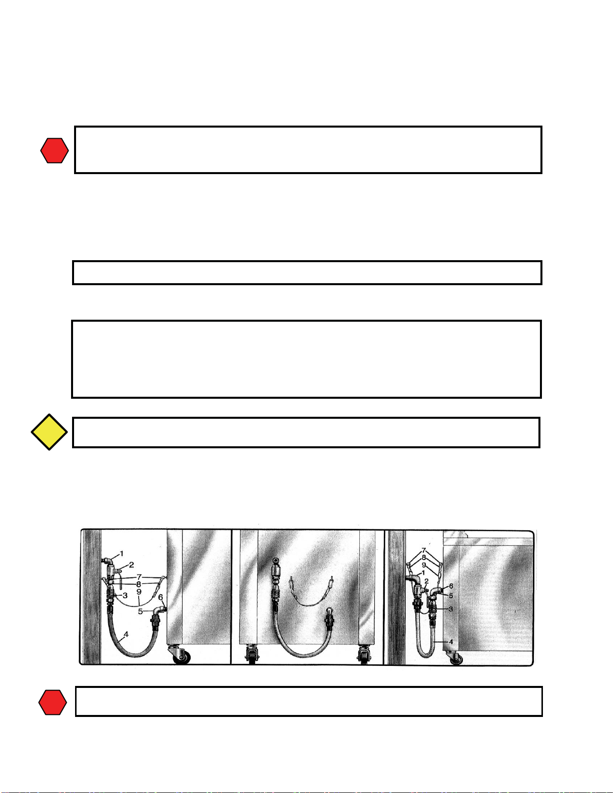
3. Connect the gas manifold to the building gas supply line by means of a CSA Group APPROVED flexible gas line as
shown in the figure below.
CONNECT-IT Inc. 3⁄4" (19mm), 1" (25mm) and 1 1⁄4" (32mm) flexible gas hose 4 feet long (1219mm) with a quick disconnect coupling on one end is available from Ultrafryer Systems under PN 24322 (3⁄4" (19mm) hose), PN 24323
(1" (25mm) hose) and PN 24456 (1 1⁄4" (32mm) hose). These hoses are equipped with a fusible link, which melts at 361°F
(183ºC) that will SHUT OFF the gas supply when it melts. Reference Installation Instructions sheet provided with hose
for additional information. A 44" (1119mm) long restraining device is also available under PN 24324. Install as shown
below between the wall and the fryer using existing mounted hardware or add hardware to the wall and fryer making a
secure connection at each ends.
NOTE:
TYPICAL GAS CONNECTION
1. BUILDING GAS SERVICE LINE 6. APPLIANCE MANIFOLD/NIPPLE
2. MAIN GAS CUT-OFF VALVE 7. EYELET FASTENERS
3. CONNECT-IT QUICK-DISCONNECT 8. SPRING HOOK
4. FLEX-CON CONNECTOR 9. RESTRAINING CHAIN
5. ELBOW
CAUTION:
WARNING:
Page 13
13
30A276 Dec 2016 Rev B
D. GAS CONNECTION: The gas supply (service) line must be the same size or greater than the inlet line of the appliance.
THE GAS SUPPLY LINES MUST BE SIZED TO ACCOMMODATE ALL THE GAS FIRED EQUIPMENT
THAT MAY BE CONNECTED TO THAT SUPPLY. Refer to the Inlet Gas Line Sizing Table and inlet gas require-
ments.
NOTE:
1. Manual shut off valve: This supplier-installed valve must be installed in the gas service line ahead of the appliance and in
a position where it can be reached quickly in the event of an emergency.
2. Pressure regulator: All commercial cooking equipment must have a pressure regulator on the incoming service line for
safe and efficient operation, because service pressure may fluctuate with local demand. External regulators are not required on this fryer, as that function is performed by a combination gas control valve, however if the incoming pressure is
in excess of 1⁄2 psig, a step-down regulator will be required.
3. Natural gas: Natural gas fryers require 7” (178mm) water column (W.C.) “inlet” pressure to the fryer’s combination gas
control valve for proper operation, when all gas units are operating simultaneously. Propane gas fryers require
14" (355mm) water column (W.C.) “inlet” pressure to the fryer’s combination gas control valve for proper operation,
when all gas units are operating simultaneously. This “inlet” pressure MUST be checked with a manometer PRIOR to
placing the fryer in operation.
WARNING:
4. Combination gas control valve: The correct combination gas control valve and orifice is installed at the factory for
NATURAL and PROPANE units based on each Purchase Order. This valve should be CHECKED/ADJUSTED by
qualified service personnel using proper test equipment for the following “OUTLET” gas pressure PRIOR to start-up of
a fryer. NATURAL GAS FRYERS 7" (178mm) W.C. PROPANE FRYERS 14" (355mm) W.C.
5. Rigid connections: Check any installer-supplied intake pipe(s) visually and/or blow them out with compressed air to clear
dirt particles, threading chips or any other foreign matter before connecting to the service line as these particles may clog
the orifice when gas pressure is applied. All connections must be tested with a soapy solution before lighting the fryer.
DO NOT USE AN OPEN FLAME TO CHECK FOR LEAKS! Putting an open flame beside a new connection is not
only dangerous, but will often miss small leaks that a soapy solution would find.
6. Flexible Couplings and Connectors: The installation is to be made with a connector that (1) complies with the Standard
for Connectors for Movable Gas Appliances, ANSI Z21.69 (CSA 6.16), and a quick-disconnect device that complies
with the Standard for Quick-Disconnect Devices for Use With Gas Fuel, ANSI Z21.41 (CSA 6.9) (2) adequate
means must be provided to limit the movement of the appliance without depending on the connector and the quick disconnect device or its associated piping to limit the appliance movement and (3) the location(s) where the restraining
means may be attached to the appliance shall be specified. DOMESTIC CONNECTORS ARE NOT SUITABLE!!!
7. Fryer Service: The fryer is equipped with swivel casters. To service the fryer:
a) Remove / unplug power supply from fryer
b) Turn “OFF” gas supply at the supply source.
b) Disconnect the flexible gas line quick-disconnect
c) Disconnect restraint means and roll fryer out for rear service access.
d) When the fryer is re-positioned, be sure to reconnect the restraint and level the fryer.
E. ELECTRICAL CONNECTION: The MAXIMUM current draw per vat at Initial Start-up or during a
Warm-up Cycle will be 3 Amperes at 120 Volts. When running the Filter System simultaneously allow for an additional 3
Amperes. Refer to the wiring diagram attached to the inside of the Service Access door for internal electrical connections.
WARNING:
Sealant used on all pipe joints must be resistive to natural and propane gas.
WARNING
IF THE “INLET” GAS PRESSURE AT THE FRYER’S COMBINATION GAS CONTROL VALVE “EXCEEDS”
1⁄2 lb/in2 (.035 kg/cm2) OR APPROXIMATELY 11” (280mm) W.C., AN EXTERNAL REGULATOR MAY BE
NEEDED TO PREVENT DAMAGE TO THE COMBINATION GAS VALVE, AND VOIDING OF WARRANTY.
WARNING
(ELECTRICAL GROUNDING INSTRUCTIONS)
THIS APPLIANCE IS EQUIPPED WITH A THREE-PRONG (GROUNDING) PLUG FOR YOUR PROTECTION
AGAINST SHOCK HAZARD AND SHOULD BE PLUGGED DIRECTLY INTO A PROPERLY GROUNDED
THREE-PRONG RECEPTACLE. DO NOT CUT, REMOVE OR OTHERWISE BYPASS THE GROUNDING
PRONG ON THIS PLUG!
Page 14
14
30A276 Dec 2016 Rev B
F. Ultrastat 23 Cooking Computer
The Ultrastat 23 Cooking Computer is a high performance, microprocessor-based electronic controller designed for use in
commercial appliance temperature and timing control applications. Utilizing a microcontroller board, membrane switch front
panel with a digital LED readout and display board, the Ultrastat 23 Cooking Computer has been customized for Ultrafryer
Systems applications by the addition of up to 10 stage cooking profiles for each of the 10 product keys; features can be
programmed to cook products under “Flex” or “Straight” timing modes. Operation of the Ultrastat 23 Cooking Computer is
covered in its Instruction Manual PN 30A216 provided with the Fryer.
15
1 2 3
4
5
14
6
8
9
10
11
12
13
7
Page 15

15
30A276 Dec 2016 Rev B
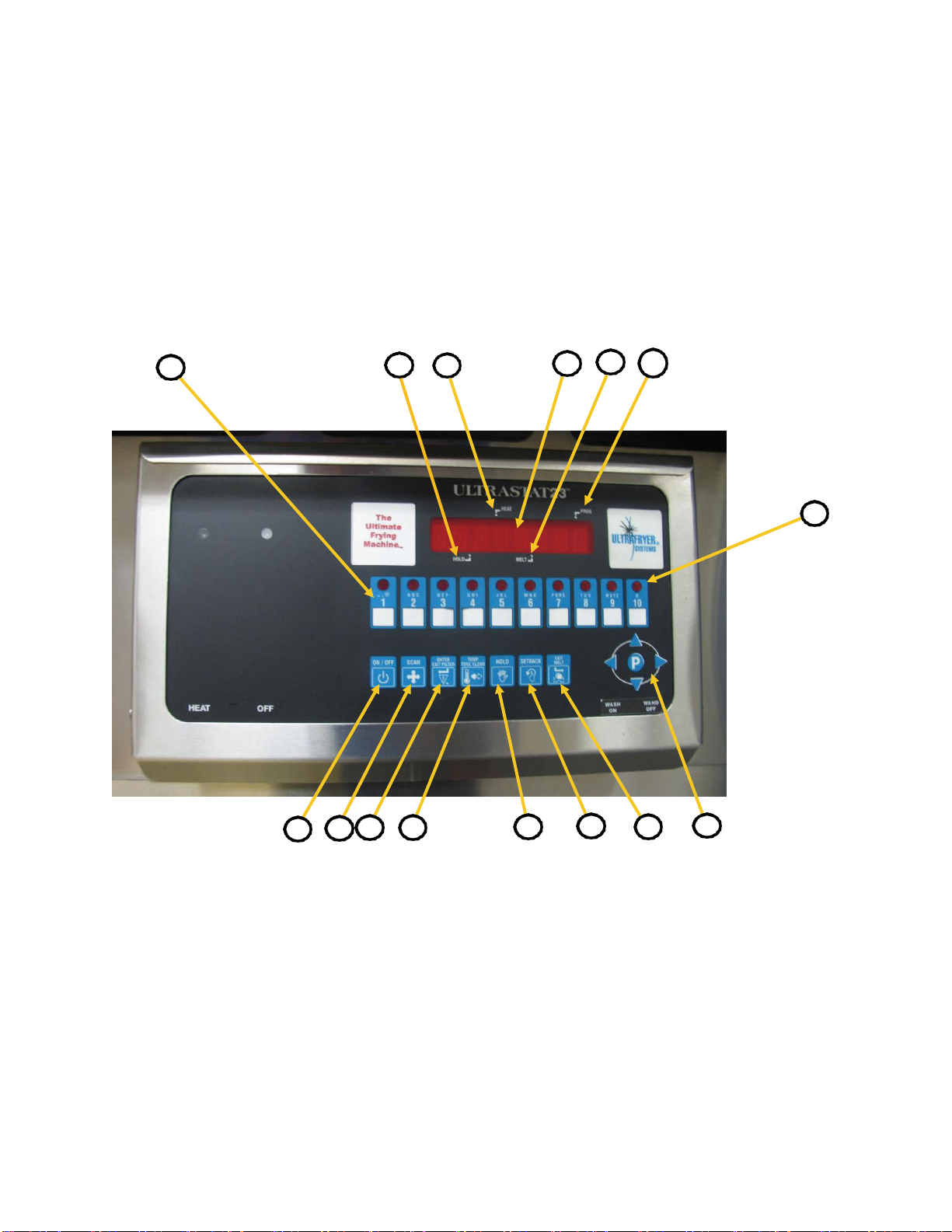
COMPUTER PANEL KEY DESCRIPTIONS
1. HOLD LAMP
When lit (bright) indicates a product hold time is being tracked.
2. HEAT LAMP
When lit (bright) indicates the computer is calling for heat.
3. DISPLAY
Displays modes, functions and operations of the computer.
4. MELT LAMP
When lit (bright) indicates the computer is in the melt cycle.
5. PROGRAM LAMP
When lit (bright) indicates the computer is in the program mode.
6. ON/OFF KEY
Turns the computer ON and OFF when the fryer power switch is in the ON position and the drain valve
lever is in the closed UP position.
7. PROGRAM KEY
a. In “operating” mode, allows access to the programming mode.
b. In “programming” mode, allows access to the operating mode and general navigation function.
8. SCAN KEY
a. In “operating” mode, displays the remaining cook time on every product currently in a cook cycle and
lights the respective products “LED” for 2 seconds.
b. In “programming” mode, steps to the next function to be programmed.
9. ENTER EXIT FILTER KEY
This key will force the fryer into the filter mode. This key is an optional feature.
10. TEMP/TOGGLE CLEAR KEY
a. In “operating” mode, displays the actual temperature followed by the programmed “set” temperature.
b. In “programming” mode, will “clear” values from a data field.
11. HOLD KEY
a. In “operating” mode, used to view remaining hold times.
12. SET BACK
a. In operating mode forces setback . Display will show “setback” and appliance will be controlled to set
back temperature instead of set point temperature.
13. EXIT/MELT KEY
a. In “operating” mode, used to manually exit the shortening melt cycle.
14. PRODUCT LED
a. When lit (bright) in the “operating” mode, identifies the product data being displayed.
b. When lit (bright) in the “programming” mode, identifies the product being programmed.
15. PROGRAMMING AND PRODUCT COOK KEY
a. In “operating” mode, used to start and stop a product’s cook cycle.
b. In “programming” mode, used to enter numerical values 1 to 10.
Page 16
16
30A276 Dec 2016 Rev B
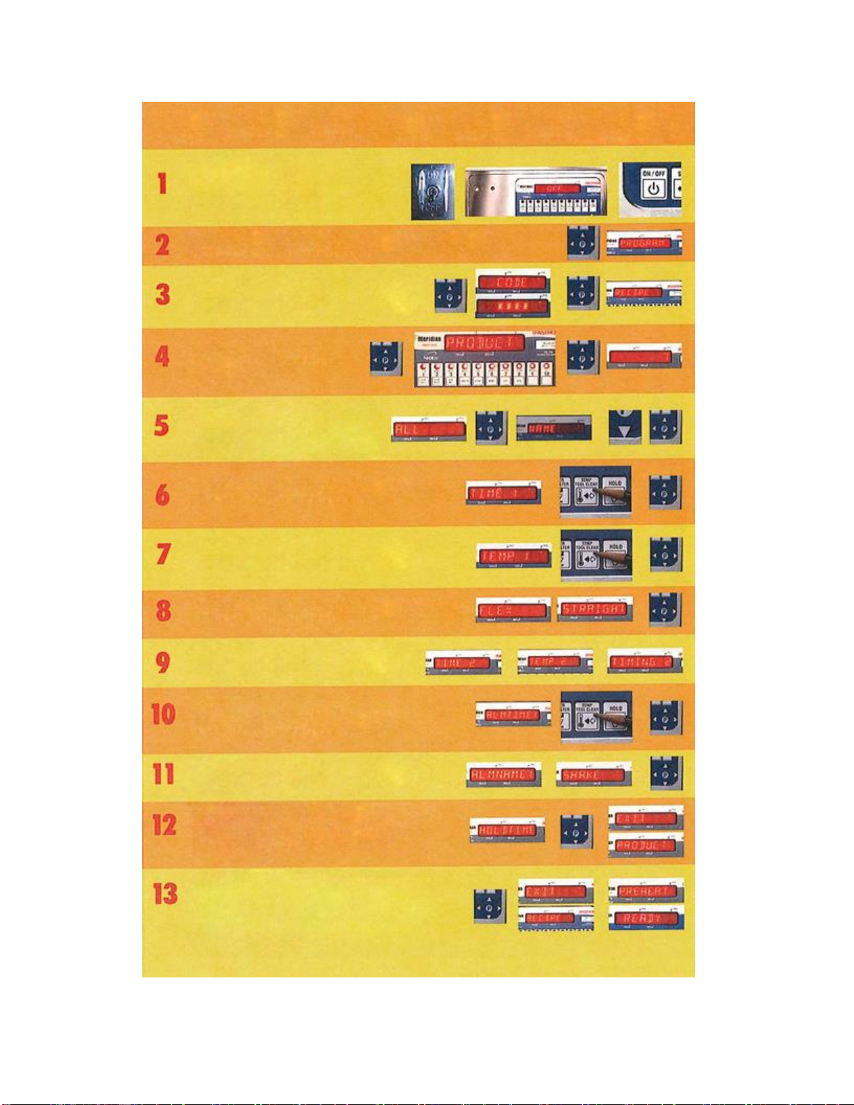
Ultrastat 23 Programming Guide
Turn Toggle ON/OFF switch to ON position and
amber power indicator lamp will illuminate.
Then press power ON/OFF key.
Push and hold the "P" key for 3 seconds to enter PROGRAMMING MODE.
PROGRAM will appear in display.
Push “P" key the second time to display CODE. Enter
“1724" and push the "P" key. RECIPE will display.
Push °P" key and “PRODUCT” will
display. Hit product key you want to
Display shows ‘‘ALL”. Push “P” key to program
each function and "NAME" appears. To change
hit the “DOWN ARROW’ and scroll to find the
word you want in the library. Then push the “P”
key to enter it and go to the next item.
'TIME 1" will display. To change the time hit "TOGGLE CLEAR”
index the time you want on the number pad and press the “P*
"TEMP 1" will display. To change hit “TOGGLE CLEAR”
and key in the amount you v/ant and hit the “P” key.
"FLEX" or "STRAIGHT'1 time will appear. To change from one to
the other, hit the left arrow key. Then hit the “P" key to save it.
Display shows “TIME 2". Repeat steps 6, 7, and 8 for
each profile. After the last profile, display will show
To change "ALARM TIME 1" hit “TOGGLE CLEAR" and
index what you want on the number keys and hit the “P”
To change “ALARM NAME” hit “DOWN ARROW’ and
scroll until you find the name you want. Then hit the “P"
Display will show “HOLD TIME 1”. For most applications this
is not used so exit at this point. To exit press the “DOWN
ARROW' key repeatedly until "EXIT'' shows on the display.
Then hit the "P" key. “PRC DUCT" will show on the display.
Then hit the “UP ARROW* key and display will show “EXIT".
Hit the “P" key and display shows “RECIPE”. Hit the "UP
ARROW again then hit "P” key and "PREHEAT'* or “READY”
should appear. You are now out of program mode and ready
to operate with the latest changes.
Page 17
17
30A276 Dec 2016 Rev B
ULTRASTAT 23 START-UP AND COOKING COMPUTER OPERATION
NOTE:
The following are abbreviated operating procedures for a fryer equipped with an Ultrastat 23 Cooking Computer. The attached
Ultrastat 23 Ultrafryer Computer Operating Instructions, Manual PN 30A216, contains DETAILED Operating, Filtering, BoilOut and Programming Instructions.
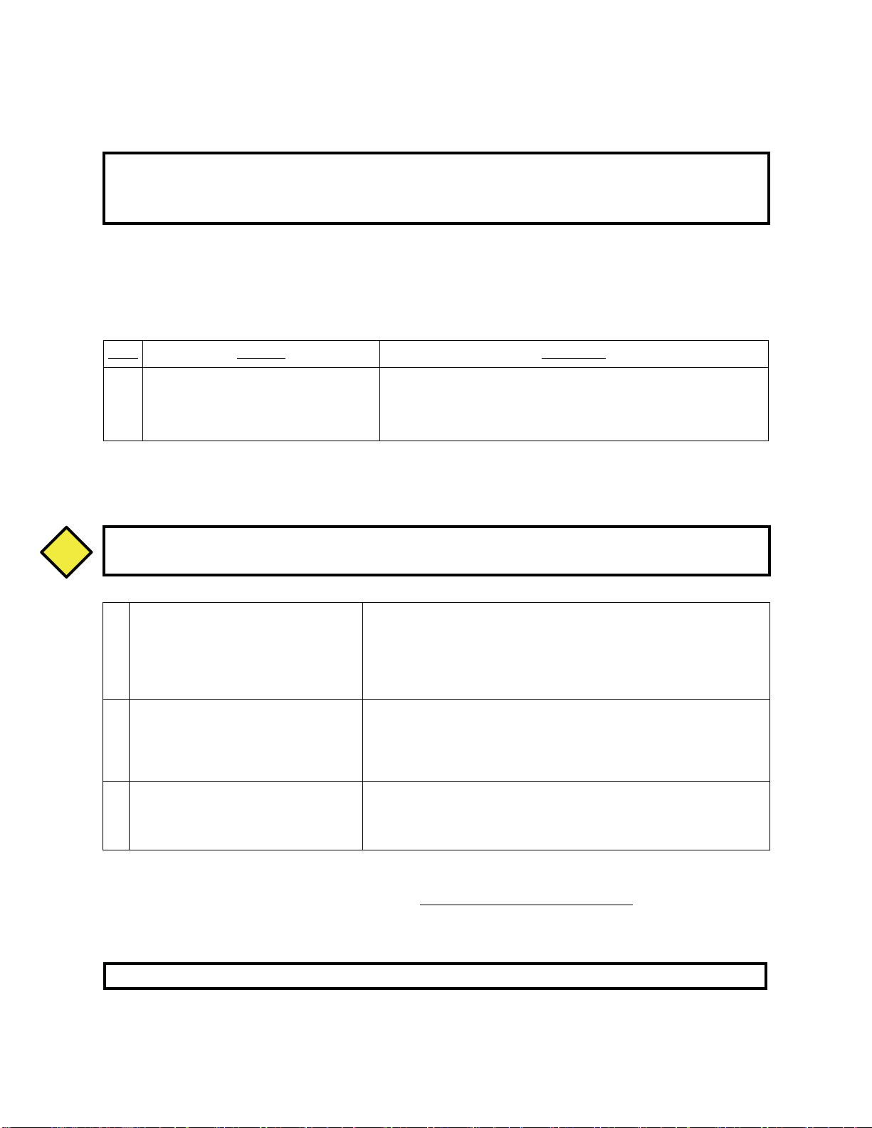
START-UP and COOKING
ULTRASTAT 23 START-UP - Safely start-up an gas fryer equipped with an Ultrastat 23 Cooking computer as follows:
STEP
ACTION
RESPONSE
1
ENSURE the drain valve lever on the fryer
is in the CLOSED position, shortening is at
the proper level, then turn the fryer ON/OFF
switch to the on position.
A. The AMBER Power lamp beside the ON/OFF switch will LIGHT.
B. The fryer heat exchanger will power up and begin to heat the
shortening.
CAUTION:
2
Turn the Computer ON by depressing the
computer ON/OFF button.
A. The MELT lamp will LIGHT to indicate the computer is in the SHORT-
ENING MELT MODE.
B. The HEAT lamp on the computer and the RED heat mechanism indicator
lamp on the fryer will cycle ON and OFF indicating the heat mechanism
is periodically being turned ON and OFF to gently heat the shortening.
3
Once the Melt Limit Temperature is
reached depress the EXIT MELT BUTTON on the computer to cancel the
SHORTENING MELT MODE.
A. “HEATING” will appear in the computer display indicating shortening
temperature is more than 10˚F (5˚C) below the set-point temperature.
B. The HEAT lamp on the computer and the RED heat mechanism indica-
tor lamp will remain ON until the set-point temperature is reached.
4
When “READY” appears in the Computer
display indicating the SET-POINT TEMPERATURE of the shortening has been
reached, a COOK cycle can be initiated.
A. Stir the shortening several times to ensure that all the shortening has
reached the set point temperature.
ULTRASTAT 23 COOKING COMPUTER PROGRAMMING
Program the Ultrastat 23 Cooking Computer according to the Computer Operating Instructions Manual
(PN 30A216) provided with the Fryer.
NOTE
1) The computer will keep the fryer in the melt cycle until the exit melt button is manually depressed.
2) The computer cannot be taken out of the shortening melt mode until the shortening temperature reaches the melt
limit temperature. The melt limit temperature is factory set for a high exit temperature (135˚F/57˚C) or a low
exit temperature (100˚F/38˚C).
CAUTION
PRIOR TO PROCEEDING TO NEXT STEP, VISUALLY CHECK THAT THE HEAT EXCHANGER IS
COVERED WITH AT LEAST 2” (51mm) OF SHORTENING.
Programming of an Ultrastat 23 cooking computer should only be performed by a store manager or area supervisor.
Page 18

18
30A276 Dec 2016 Rev B
GENERAL COOKING
Most products should be cooked with a shortening temperature about 350˚F (177˚C); however, each product should be
cooked at the LOWEST temperature that produces a high quality product while obtaining maximum usage of the shortening.
WARNING:
NOTE:
POWER FAILURE
This fryer cannot be operated during power failures. DO NOT attempt to bypass safety and manually operate fryer.
CAUTION:
THE FRYER HAS A RESTRAINT ATTACHED TO THE WALL TO LIMIT MOVEMENT AND TIPPING IN
ORDER TO AVOID SPLASHING OF HOT LIQUID.
MOVING THE FRYER WITH HOT COOKING OIL IN THE VESSEL MAY CAUSE SPLASHING OF THE HOT
LIQUID CAUSING SEVERE BURNS.
IF MOVING THE FRYER IS REQUIRED FOR CLEANING OR SERVICING. TAKE THE REQUIRED STEPS OF
REMOVING THE RESTRAINT, POWER AND GAS CONNECTIONS BEFORE MOVING THE FRYER AND
MAKE SURE THE COOKING OIL IN THE VESSEL IS COLD OR HAS BEEN REMOVED FROM THE VESSEL
TO LIMIT ACCIDENTAL BURNS OR DAMAGE TO THE FRYER.
CAUTION
Startup steps 1, 2, 3 and 4 will have to be repeated each time any of the following occurs:
Drain valve is open, fryer ON/OFF swith is turned OFF to filter shortening or boil-out a fryer. Fryer ON/OFF swith is
turned OFF at closing or any other reason.
I – DO USE A HIGH QUALITY SHORTENING TO ACHIEVE A CONSISTENT QUALITY PRODUCT AND
LONG TERM SAVINGS
II – DO NOT SALT PRODUCTS OVER THE FRYER AS SALT QUICKLY DETERIORATES THE
SHORTEN ING AND FLAVORS OTHER PRODUCTS COOKED IN THE SAME SHORTENING
III – DO FILTER SHORTENING AFTER THE LUNCH AND DINNER RUSH AND MORE OFTEN IN A
HIGH SALE VOLUME STORE; AND BOIL-OUT THE FRYER EVERY 7 DAYS
WARNING
Page 19

19
30A276 Dec 2016 Rev B
When the Computer is taken out of the SHORTENING MELT MODE each morning, shortening in the fryer vat will be
heated to its SETPOINT temperature, “HEATING” will appear in the display to indicate the shortening temperature is
MORE than 20˚F (-6.6˚C) BELOW the set point temperature. When shortening temperature rises to the SETPOINT tempera-
ture, “READY” will appear in the display indicating a COOK CYCLE can be started.
STARTING A COOK CYCLE
To start a cook cycle simply press the product key for the product you wish to cook. Cook time will be displayed
“3:00” (example) and this time will immediately start to count down in minutes and seconds. It will count down to “ :00”
followed by a beeping signal. To turn this signal OFF and reset the Computer, press the same product key used to start the
COOK CYCLE.
CANCELLING A COOK CYCLE
If a cook cycle was inadvertently started it may be cancelled two (2) ways:
1) Press and hold the same product key used to start the cook cycle for 4 SECONDS. This prevents an accidental start of a
cook cycle while a product is being cooked.
2) A cook cycle can be CANCELLED at any time by turning the fryer ON/OFF Switch to the OFF position.
Press and Hold
Product Key
ON/OFF Switch
Page 20

20
30A276 Dec 2016 Rev B
SHORTENING FILTRATION PROCEDURE &
WASH WAND OPERATION
Page 21

21
30A276 Dec 2016 Rev B
SHORTENING FILTRATION PROCEDURE
Fryer Filtration with Filter Tub and Suction Line Assembly
1
Service access Door
2
Suction Line Connection for Filter Pump (on bulkhead)
3
Shortening Drain Lever (one per vat)
4
Vat Return Lever (one per vat)
5
Wash Wand Connection
6
Red-Handled Lever for Wash Wand (one lever per fryer)
7
Filter Tub Guide
8
Suction Line Assembly
9
Filter Tub
1 3 4 6 7 2 8
5
9
Page 22

30A276 Dec 2016 Rev B
22
COOK COMPUTER CONTROL PANEL
Effective and safe filtration is accomplished as follows:
1. Turn on the computer on the vat that is to be filtered.
2. Turn the “HEAT/OFF” Switch (labeled “Cook/Filter” on earlier models) on the fryer vat to “OFF”
(or to “Filter” on earlier models) and skim the shortening to remove any floating crumbs. Consult
company’s operational procedure on the recommended amount of FILTER AGENT in the fryer vat
and then thoroughly stir the filter agent into the shortening using the skimmer.
CAUTION:
3. Carefully open the drain valve on the vat to be filtered by turning the Drain Lever slightly
Counterclockwise. When the bottom of the filter tub is covered
4. When all shortening in the vat has drained into the filter tub, use the Drain Rod to stand the wire rack
on one side of the vat.
5. Use the drain rod to break up the sediment caked on the inside of the vat and to pull the sediment
Toward and into the drain valve opening.
6. Use a scraper to remove encrusted material from the sides of the vat and a stropping pad to remove
Carbon buildup from the top and sides of the heat mechanism.
NOTE
7. Once all shortening and debris are drained, turn on the vat pump by turning the Vat Return Lever
(previously “pump lever”) counterclockwise. The pump will begin to return shortening into the vat.
PRIOR TO PROCEEDING TO THE NEXT STEP, DON SAFETY GOGGLES, NEOPRENE-INSULATED GLOVES
AND AN APRON.
CAUTION
1
Amber “Power” Indicator
Lamp
2
Red “Burner” Indicator Lamp
3
“Heat/Off” Toggle Switch
4
Cook Computer (Ultrastat 23
Computer shown)
1 2 4
3
In the event that the wash wand is required, make sure that the vat return lever is turned on to the
“CLOSED” position before activating the wash wand, refer to the “Wash Wand Operation” section for
further instructions.
Page 23

23
30A276 Dec 2016 Rev B
8. Once the vat is filled, turn the Vat Return Pump Lever clockwise to the “closed” position to turn the pump off.
9. Repeat the above procedure for each vat.
NOTE:
If the return flow to the vat is decreased, scrape sediment from the filter screen or pad.
CAUTION:
CAUTION
NEVER USE THE SUCTION HOSE OR ANY OTHER DEVICE TO DRAW THE SHORTENING INTO
THE PUMP AND FRYER PLUMBING WITHOUT FIRST GOING THROUGH THE FILTER MEDIA
(FILTER SCREEN OR FILTER PAD OR FILTER PAPER). SUSPENDED PARTICLES THAT ARE
NOT FILTERED OUT BEFORE ENTERING THE PUMP CAN DAMAGE THE PUMP AND CAUSE
BLOCKAGES IN THE FRYER FILTER PLUMBING.
Page 24

24
30A276 Dec 2016 Rev B
WASH WAND OPERATION
For fryers with “R” style filtration
Wash Wand and Filtration Controls
CAUTION:
1
“Heat/Off” Toggle Switch (labeled “Cook/
Filter” on older models
Must be switched to “off” (or to “filter” on older
models) during wash wand operation.
2
Drain Lever
Operates the main drain valve, which drains the
shortening from the vat to the drain trough to the filter tub.
3
Wash Wand (Red) Handle
(Shown in the “on” position) Causes shortening to
flow into the Wash Wand.
NOTE: The Pump Activation Switch
(T&R Switch) must also be turned on for
Wash Wand operation.
CAUTION
CAUTION: Wash Wand and shortening
are HOT!
4
Vat Return Pump Lever
Turns on the pump to the Wash Wand.
5
Pump Activation Switch (T&R Switch)
Activates the pump to the Wash Wand.
NOTE: On a 6-Vat fryer, the Pump Activation
Switches (T&R Switch) are located underVat #2 and
Vat#5. On a 5-Vat fryer, the switches are located
under Vat#2 and Vat#4. Each Pump Activation
Switch (T&R Switch) operates independently from
any other Pump Activation Switch (T&R Switch) that
mat be present on the fryer.
NOTE: The Wash Wand (Red) handle must also be
in the “open” position (handle pointing downward)
for Wash Wand operation.
6
Wash Wand Connection
(Shown with Wash Wand installed)
NOTE: The Wash Wand must be installed prior
to turning the Wash Wand (Red) Handle and activating the Pump Activation Switch (T&R Switch).
2 3 4
1
5
6
Page 25

25
30A276 Dec 2016 Rev B
Wash Wand Operation Procedure
1. Turn off the computer on the vat that is to be filtered.
2. Turn “Heat/Off” toggle switch to “Off” (if using an older model fryer, then switch the “Cook/Filter” toggle to
“Filter”). This is the left-hand switch if the controller box has two switches.
3. Open the drain valve on the vat by turning the drain lever counterclockwise. Allow shortening to enter the drain
trough.
4. Insert the wash wand hose end into the wash wand connection fitting. (This is the fitting that does not have the
Suction line hose connected to the filter tub).
5. Place the wash wand hose nozzle into the fryer and hold the nozzle firmly against an inner wall. This will prevent
the hose from recoiling upward when the filter pump is turned on.
6. Turn the wash wand (red) handle counterclockwise and then switch the Pump Activation Switch (T&R Switch)
to the “on” position. Shortening will begin to flow into the wash wand.
NOTE:
NOTE:
7. Once sediment is removed, turn the drain lever clockwise to the “closed” position. This will allow the vat to refill.
8. When the vat is filled, switch the Pump Activation Switch (T&R Switch) to “off”.
CAUTION:
9. Turn the wash wand (red) lever clockwise to the “closed” position.
10. Disconnect the wash wand from the wash from the wash wand connection fitting.
NOTE:
11. Repeat the above steps for each vat.
NOTE:
ALWAYS POINT THE WASH WAND TOWARDS THE INNER SIDE WALL OF THE VAT AND AWAY FROM
YOURSELF AND CO-WORKERS.
A drain rod may be required to force sediment through the drain valve.
If the wash wand handle is closed prior to the pump on, the pump motor’s thermal reset sensor will trip and disable the
motor. Once this happens, it will be necessary to wait for the motor to cool and then to press the “Reset” switch on the
end of the motor before the motor will be operational again.
When disconnected, let oil in the wash wand hose drain back into the filter tub.
If the return flow to the vat is decreased, scrape sediment from the filter screen or pad.
CAUTION
Page 26

30A276 Dec 2016 Rev B
26
CLEANING
Page 27

30A276 Dec 2016 Rev B
27
GENERAL CLEANING
Any item of equipment operates and lasts longer when kept clean and properly maintained, and the Ultrafryer is no exception.
In order for this fryer to provide years of trouble-free service, it must be CLEANED and MAINTAINED according to the
instructions listed below.
DAILY
1) Clean the fryer surfaces periodically during operating hours with a solution of sanitizer and hot water, and at closing with
stainless steel cleaner. If necessary, use a dampened type 7447 RED or 7440 BROWN (heavy duty) Scotch brite pad to
remove encrusted material. DO NOT use steel wool, abrasive cloths, cleaners, powders, metal knife, spatula or any metal
object to scrape stainless steel! Scratches on stainless steel are almost impossible to remove.
2) Filter the shortening in each fryer once a day or according to Company Policy.
CAUTION:
WEEKLY
1) BOIL-OUT the fryer vat using Boil Out Compound according to procedures in the cleaning manual provided by the
chemical provider.
2) Perform steps 1 and 2 listed above under the Daily Cleaning.
CAUTION
DO NOT ALLOW ANY CLEANING SOLUTION / WATER TO SPLASH INTO THE VESSEL OF HOT COOKING
OIL AS IT WILL CONTAMINATE THE OIL AND MAY CAUSE THE OIL TO SPLATTER, CAUSING SEVERE
BURNS.
Page 28

30A276 Dec 2016 Rev B
28
PREVENTIVE MAINTENANCE AND TROUBLESHOOTING
Page 29

30A276 Dec 2016 Rev B
29
Preventive Maintenance
Minimal maintenance is required on the fryer because of its design and the materials used in the manufacturing process. However, some preventive maintenance and inspection must be performed periodically to prevent break downs which could curtail
food sales. Any preventive maintenance or inspection should be accomplished with CAUTION while the fryer is in operation
since HOT liquid shortening could cause severe burns. If service or repair is required, all gas and electric power MUST BE
TURNED OFF PRIOR to performing any service or repair. The following chart describes the minimum items to be inspected
and the inspection interval:
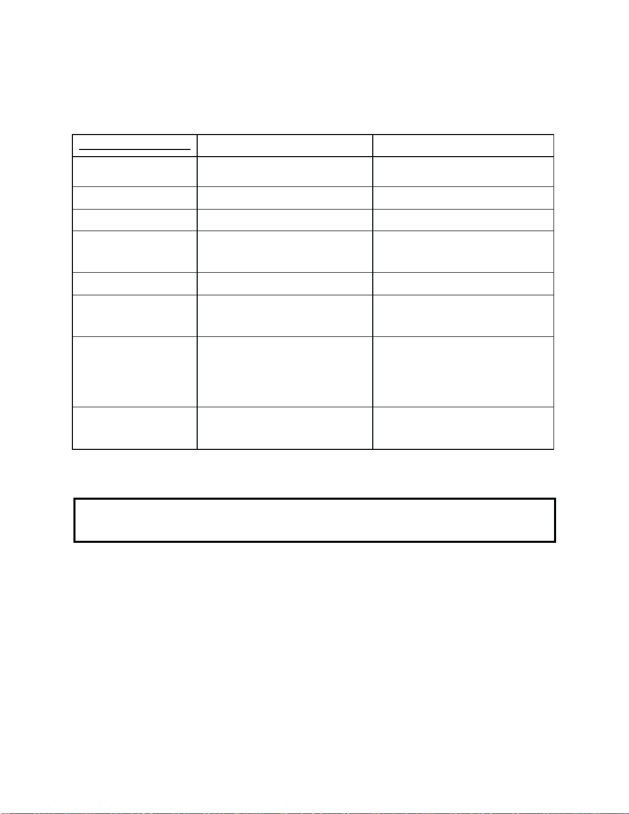
Table 1. Daily Preventive Maintenance Inspection Schedule.
Item
Inspection Description
Grease Filters
Clean grease filters in the exhaust hood evening and allow them to dry overnight
Filter Tube
Thoroughly clean the filter tub assembly prior to leaving the store at closing.
Note: Ensure the wash down hose is hung in an upright position (by one end) so shortening can drain into a container.
Table 2. Weekly Preventive Maintenance Inspection Schedule.
Item
Inspection Description
Drain Valve & Shortening
return levers
Determine that all levers are securely attached and that they can be easily operated.
Drain Hoses
Inspect the suction line, wash down and if applicable, the shortening disposal hose
for any evidence of deterioration.
Plumbing Heat Tape
Ensure that the insulation and electric heat tape that wrapped around the plumbing
directly behind the drain through has not been damaged.
Temperature Sensing Probes
During boil-out of the fryer, inspect the temperature and high limit sensing probes
for any visual damage.
Page 30

30
30A276 Dec 2016 Rev B
TROUBLESHOOTING
A. GENERAL: The problems and possible solutions listed in the troubleshooting chart below are typical problems that are
frequently encountered. ONLY qualified repairmen are to use the troubleshooting chart to repair this fryer. In the event a main
burner malfunction occurs, perform the following checks PRIOR to contacting a repairman:
1. Check that the fryer electrical plug is connected to an electrical receptacle.
2. Ensure the applicable Circuit Breaker is in the ON position and that the fryer ON/OFF switch is in the ON position.
3. Ensure the applicable fryer control has been placed in the EXIT MELT mode.
4. Ensure the gas supply line quick-disconnect coupling is SEATED on the gas manifold fitting.
5. Determine that the blower is operating.
B. TROUBLESHOOTING CHART: Should a problem occur that cannot be corrected after performing the above CHECKS,
contact an AUTHORIZED repairman and/or Ultrafryer Systems Customer Service 1-800-525-8130 and provide the information acquired while performing these checks.
ITEM
PROBLEMS
POSSIBLE SOLUTIONS
1
Ignition Lockout
1.) Harness connection to gas valve
2.) Gas valve or gas pressure
3.) All harness connections
4.) Electrode
5.) Interconnecting wiring malfunction
6.) Ignition module malfunction
8.) Grounding Status
2
No spark, No blower
1.) Harness connections
2.) Probe lead wires
3.) Open probe
4.) Controller
3
“Puffing” during normal start up
1.) Incorrect gas pressure
2.) Cracked electrode
3.) Electrode gap exceeded
4
Burner lights but will not maintain flame
1.) Igniter / flame sense misalignment
2.) Insufficient gas pressure
5
Excessive Heat
1.) Incorrect temperature offset selected
2.) Set Temperature exceeding 400 deg F
3.) Temperature probe malfunction
4.) Cooking control malfunction
5.) Interface board malfunction
6.) Gas pressure incorrect
6
Low heat
1.) Incorrect temperature offset selected
2.) Cooking control malfunction
3.) Temperature probe malfunction
4.) High limit tripped
5.) Interface board malfunction
6.) Gas pressure incorrect
7
Intermittent problems
1.) High ambient temperatures
2.) Wiring connections loose
8
No power to cooking control,
fryer does not heat
1.) Is display “OFF” when powered
2.) Main circuit breaker off
3.)Transformer inoperative
4.) Interconnecting wiring malfunction
Page 31

31
30A276 Dec 2016 Rev B
TROUBLESHOOTING CHART CONTINUED:
Should a problem occur that cannot be corrected after performing the above CHECKS, contact an AUTHORIZED repairman
and/or Ultrafryer Systems Customer Service 1-800-525-8130 and provide the information acquired while performing these
checks.
ITEM
PROBLEMS
POSSIBLE SOLUTIONS
9
High limit thermostat shutting down system
1.) Shortening level below minimum fill line
2.) Probe malfunction
3.) Controller malfunction
10
Excessive time to melt shortening
1.) Melt cycle timing incorrect
2.) Insufficient gas pressure
3.) Probe malfunction
4.) Control malfunction
11
Dry fire fry tank
1.) No shortening in vat
2.) Control malfunction
3.) Probe malfunction
CAUTION:
CAUTION
ENSURE REPAIRMEN ARE ADVISED THAT FRYER RESTRAINTS MUST BE DISCONNECTED/CONNECTED.
IF A FRYER IS TO BE MOVED DURING MAINTENANCE OR REPAIR, AND THAT ELECTRICAL POWER AND
GAS MUST BE TURNED OFF PRIOR TO PERFORMING ANY MAINTENANCE OR REPAIR.
Page 32

32
30A276 Dec 2016 Rev B
TECHNICAL ASSISTANCE, WARRANTY PARTS &
REPLACEMENT PARTS ASSISTANCE
Page 33

33
30A276 Dec 2016 Rev B
TECHNICAL ASSISTANCE - Contact an authorized service agent or the Customer Service Department, Ultrafryer
Systems at 1-800-525-8130 for Technical Assistance.
E-Mail technical assistance at: techserv@ultrafryer.com
WARRANTY PARTS - Contact the Customer Service Department, Ultrafryer Systems at 1-800-525-8130 for
Parts Assistance.
E-Mail Customer Service at: techserv@ultrafryer.com
REPLACEMENT PARTS - Contact the Customer Service Department, Ultrafryer Systems at 1-800-525-8130 for
Replacement Parts Assistance.
Page 34

34
30A276 Dec 2016 Rev B
RECOMMENDED SPARE PARTS
Page 35

35
30A276 Dec 2016 Rev B
A. RECOMMENDED SPARE PARTS
PREMIX GAS FRYER
RECOMMENDED SPARE PARTS LISTING
DESCRIPTION
PN
Blower Premix 5.0 Power Burner and Gas Valve (80,000 BTU/hr (84.35 MJ/hr))
17A033
Blower Premix 5.0 Power Burner and Gas Valve (110,000 BTU/hr (116.06 MJ/hr))
17A031
Gasket, Blower Motor / Manifold IDE
22A810
Burner Infrared
22A818
Rod, Ignitor Infrared Burner F/22A818
18610
Gasket, Mount Infrared Burner
22A817
Module, Ignitor Spark Single
18A385
Relay, 24V AC Flange Mounted
18A034
Relay, 24V AC DELAY ON MAKE
18A102
Control, 24VAC Universal Gas Blower (PWM)
23A462
Switch, Air Pressure
18A291
Switch, HI Limit
19B783
Probe, Temp Thermistor
18A006
To minimize downtime on the premix gas fryer upon failure of a component part, at least one (1) of the following items should
be kept as a spare part in a local area:
Page 36

36
30A276 Dec 2016 Rev B
PARTS IDENTIFICATION
Page 37

37
30A276 Dec 2016 Rev B
1
22A342
Board, Interface 24 pin CON PNP
2
18A102
Relay, 24 VAC Delay ON MAKE
3
23A462
Control, 24 VAC Universal Gas Blower (PWM)
4
18A034
Relay, 24 VAC Flange-mounted
5
18A081
Switch Toggle DPST 15A 125V
1 2 3
4
5
Inside Controller Box
Page 38

38
30A276 Dec 2016 Rev B
1
19D042
Box Mount, Infrared Burner
2
22A818
Burner Infrared
3
18611
Rod, Ignitor Infrared Burner
4
22A817
Gasket, Mount Burner Box
5
18A313
Box, Power Distribution No ACC PNP
6
12D132
Box Assembly, Pump Control
7
18A385
Module, Ignitor Spark Single
7
1 2
3 4
5
6
Cabinet Front View
Page 39

30A276 Dec 2016 Rev B
39
1
18A006
Probe, Temp Thermistor
2
19B783
Switch, Hi Limit
3
24A270
Fitting, Compression Male 3/8 NPT
1
2 3
Cabinet Side View
Page 40

30A276 Dec 2016 Rev B
40
1
19D059
Box, Blower w/Flue
2
22A819
Gasket, Blower Box
3
19D079
Baffle, Agitator Rear
4
17A033
Blower Premix 5.0 Power Burner/Gas Valve (80,000 BTU/hr (84.35 MJ/hr))
4
17A031
Blower Premix 5.0 Power Burner/Gas Valve (110,000 BTU/hr (116.06 MJ/hr))
5
22A810
Gasket, Blower Motor/Manifold
6
18A291
Switch, Air Pressure SMD 1204
7
18A034
Relay, 24 VAC Flange Mounted
8
18A034
Relay, 24 VAC Flange Mounted
1 2
3
4 5
Cabinet Rear View
Page 41

30A276 Dec 2016 Rev B
41
1
18A291
Switch, Air Pressure SMD 1204
2
18A034
Relay, 24 VAC Flange Mounted
3
18A034
Relay, 24 VAC Flange Mounted
2
1
3
Cabinet Rear View
Without Relay Cover
Page 42

42
30A276 Dec 2016 Rev B
SERVICE PROCEDURES AND ADJUSTMENTS
Page 43

43
30A276 Dec 2016 Rev B
HARMONIC TONE
Harmonic Tone (hum) at First Start, fryer will begin heating in low fire and a few seconds later go to high fire. There will be a
harmonic tone that is NORMAL to hear. As fryer continues to heat, harmonic tone will dissipate and become less noticeable.
GAS VALVE
WARNING:
WARNING:
The gas valve is considered part of the Blower
WARNING:
Premix 5.0 Power Burner and Gas Valve assembly. If
the gas valve fails and needs to be replaced, you must order a complete blower / gas valve assembly (burner). The reason for
this is every blower / gas valve assembly (burner) is set up at the factory to operate at the most efficient level possible. This set
up procedure can not be duplicated inn the field.
MODULATING GAS VALVE ADJUSTMENTS
WARNING:
WARNING:
The modulating gas valve is adjustable at the factory and requires no adjustments. If the modulating
gas valve needs to be
WARNING:
replaced, the new gas valve from the factory will be adjusted properly and will only need to have the gas pressure verified
coming into the gas valve
ALL GAS JOINTS DISTURBED DURING SERVICING MUST BE CHECKED FOR
LEAKS. CHECK WITH A SOAP AND WATER SOLUTION (BUBBLES).
DO NOT USE AN OPEN FLAME
WARNING
SHUT OFF THE GAS BEFORE SERVICING THE FRYER.
WARNING
DISCONNECT THE ELECTRICAL POWER TO THE FRYER.
WARNING
ALL GAS JOINTS DISTURBED DURING SERVICING MUST BE CHECKED FOR LEAKS.
CHECK WITH A SOAP AND WATER SOLUTION (BUBBLES).
DO NOT USE AN OPEN FLAME
WARNING
DISCONNECT THE ELECTRICAL POWER TO THE FRYER.
SHUT OFF THE GAS BEFORE SERVICING THE FRYER.
WARNING
WARNING
Page 44

30A276 Dec 2016 Rev B
44
Temperature Probe & Hi Limit
2.75 ± .125
BOTH
Page 45

45
30A276 Dec 2016 Rev B
Infrared Burner Spark Ignitor and Flame Sensor Settings
.219 Spark Ignitor
.189 Flame Sensor & GND
Page 46

30A276 Dec 2016 Rev B
46
Ground Rod
Ground Wire Connection
Ground
Wire
Connection
Page 47

47
30A276 Dec 2016 Rev B
Control, 24 VAC Universal Gas Blower
(PWM) Settings
Gas Blower Dip Switch Settings
#1 OFF
#2 OFF
#3 OFF
#4 ON
80,000 BTU
Natural Gas High Fire = 3 (Shown)
Propane High Fire = Ø
110,000 BTU
Natural Gas High Fire = 9
Propane High Fire = B
80,000 BTU
Natural Gas Low Fire = 8 (Shown)
Propane Low Fire = 8
110,000 BTU
Natural Gas Low Fire = 8
Propane Low Fire = 8
Page 48

48
30A276 Dec 2016 Rev B
Delay on Make Setting
Setting = 2 Second
Page 49

30A276 Dec 2016 Rev B
49
LADDER AND SCHEMATIC DIAGRAM
Page 50

30A276 Dec 2016 Rev B
50
IR-18/20 80,000 BTU (84.35 MJ/hr)
Page 51

30A276 Dec 2016 Rev B
51
IR-18 110,000 BTU (116 MJ/hr)
Page 52

52
30A276 Dec 2016 Rev B
IR-18/20
Page 53

53
30A276 Dec 2016 Rev B
Page 54

54
30A276 Dec 2016 Rev B
 Loading...