

USER GUIDE & SERVICE MANUAL
SAFETY • INSTALLATION & INTEGRATION • OPERATING INSTRUCTIONS • MAINTENANCE • SERVICE
RIGHT PRODUCT. RIGHT PLACE. RIGHT TEMPERATURE. SINCE 1962.
1000 Series • 1215WC • 15" Single Zone Wine Captain® Model
USER GUIDE
u-line.com
Contents
SAFETY • INSTALLATION & INTEGRATION • OPERATING INSTRUCTIONS • MAINTENANCE • SERVICE
Intro
Safety
Safety and Warning
Disposal and Recycling
Installation
Environmental Requirements
Electrical
Cutout Dimensions
Product Dimensions
Side by Side Installation
Anti-Tip Bracket
General Installation
Grille / Plinth Installation
Door Swing
Wine Rack Installation
Extended Non-Use
Service
Troubleshooting
Warranty
Service Extended
Wire Diagram
Product Liability
Warranty Claims
Parts
Ordering Replacement Parts
System Diagnosis Guide
Compressor Specifications
Troubleshooting Extended
Door Stop
Door Adjust
Wood Trim Finishing
Operating Instructions
First Use
Control Operation
Sabbath Mode
Airflow and Product Loading
U-Line Wine Guide
Recommended Wine Storage
Maintenance
Cleaning
Cleaning Condenser
Control Quick Guide
Thermistor
Defrost
USER GUIDE
u-line.com
WELCOME TO U-LINE
Congratulations on your U-Line purchase. Your product comes from a company with over five decades of premium modular
ice making, refrigeration, and wine preservation experience. U-Line continues to be the American leader, delivering versatility
and flexibility for multiple applications including residential, light commercial, outdoor and marine use. U-Line’s complete
product collection includes Wine Captain
Door Refrigerators, Drawer Models, Freezers, Combo® Models, and more.
U-Line has captivated those with an appreciation for the finer things with exceptional functionality, style, inspired innovations
and attention to even the smallest details. We are known and respected for our unwavering dedication to product design,
quality and selection. U-Line is headquartered in Milwaukee, Wisconsin and has shipped product to five continents for over
two decades and is proud to have the opportunity to ship to you.
PRODUCT INFORMATION
Looking for additional information on your product? User Guides, Spec Sheets, CAD Drawings, Compliance Documentation,
and Product Warranty information are all available for reference and download at u-line.com.
®
Models, Beverage Centers, Clear Ice Machines, Crescent Ice Makers, Glass & Solid
PROPERTY DAMAGE / INJURY CONCERNS
In the unlikely event property damage or personal injury is suspected related to a U-Line product, please take the following
steps:
1. U-Line Customer Care must be contacted immediately at +1.800.779.2547.
2. Service or repairs performed on the unit without prior written approval from U-Line is not permitted. If the unit has been
altered or repaired in the field without prior written approval from U-Line, claims will not be eligible.
GENERAL INQUIRIES
U-Line Corporation
8900 N. 55th Street
Milwaukee, Wisconsin 53223 USA
Monday - Friday 8:00 am to 4:30 pm CST
T: +1.414.354.0300
F: +1.414.354.7905
Email: sales@u-line.com
u-line.com
SERVICE & PARTS ASSISTANCE
Monday - Friday 8:00 am to 4:30 pm CST
T: +1.800.779.2547
F: +1.414.354.5696
Service Email: onlineservice@u-line.com
Parts Email: onlineparts@u-line.com
CONNECT WITH US
Designed, engineered and assembled in WI, USA
Introduction 1
USER GUIDE
NOTICE
u-line.com
SAFETY • INSTALLATION & INTEGRATION • OPERATING INSTRUCTIONS • MAINTENANCE • SERVICE
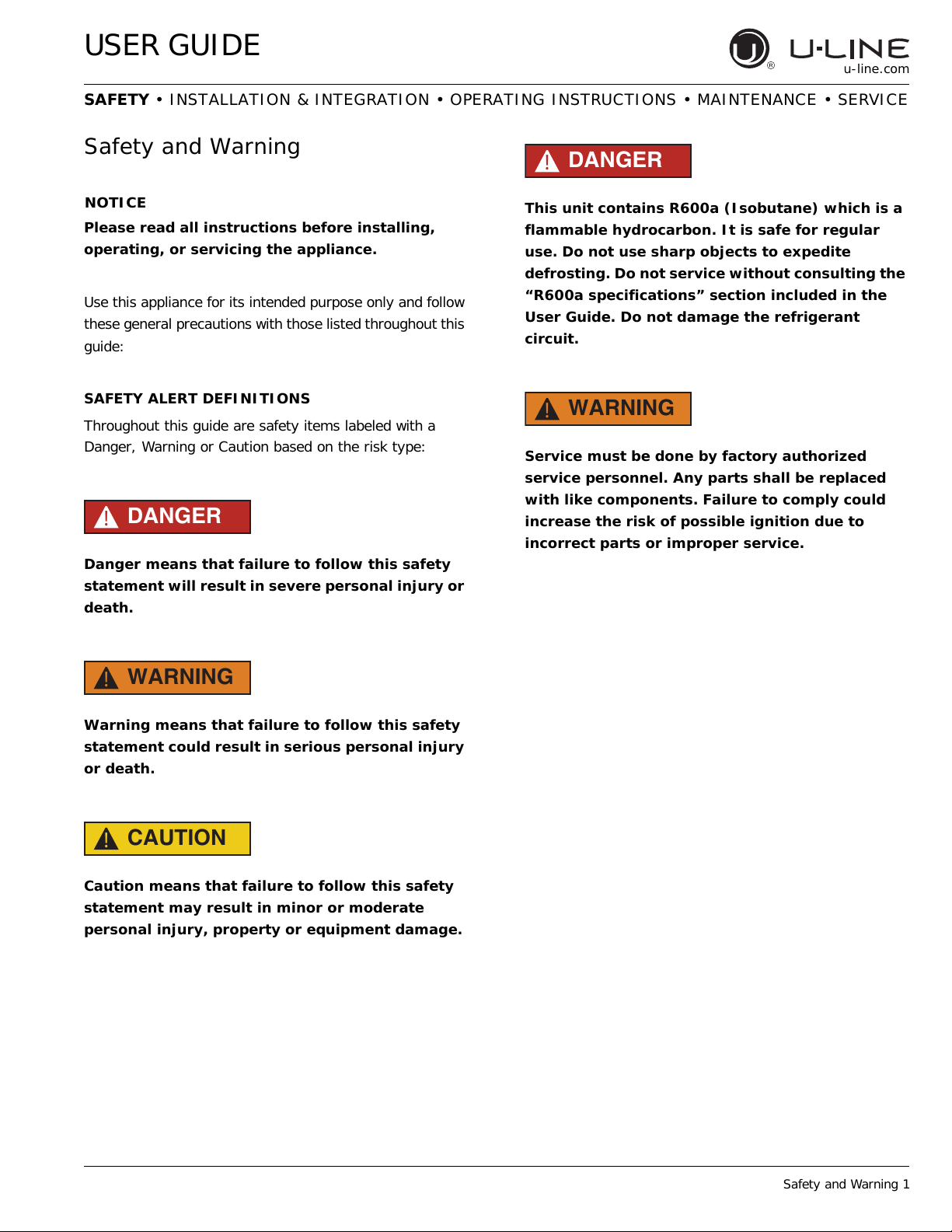
Safety and Warning
Please read all instructions before installing,
operating, or servicing the appliance.
Use this appliance for its intended purpose only and follow
these general precautions with those listed throughout this
guide:
SAFETY ALERT DEFINITIONS
Throughout this guide are safety items labeled with a
Danger, Warning or Caution based on the risk type:
DANGER
!
Danger means that failure to follow this safety
statement will result in severe personal injury or
death.
DANGER
!
This unit contains R600a (Isobutane) which is a
flammable hydrocarbon. It is safe for regular
use. Do not use sharp objects to expedite
defrosting. Do not service without consulting the
“R600a specifications” section included in the
User Guide. Do not damage the refrigerant
circuit.
WARNING
!
Service must be done by factory authorized
service personnel. Any parts shall be replaced
with like components. Failure to comply could
increase the risk of possible ignition due to
incorrect parts or improper service.
WARNING
!
Warning means that failure to follow this safety
statement could result in serious personal injury
or death.
CAUTION
!
Caution means that failure to follow this safety
statement may result in minor or moderate
personal injury, property or equipment damage.
Safety and Warning 1
USER GUIDE
u-line.com
SAFETY • INSTALLATION & INTEGRATION • OPERATING INSTRUCTIONS • MAINTENANCE • SERVICE
Disposal and Recycling
DANGER
!
RISK OF CHILD ENTRAPMENT. Before you throw
away your old refrigerator or freezer, take off
the doors and leave shelves in place so children
may not easily climb inside.
If the unit is being removed from service for disposal,
check and obey all federal, state and local regulations
regarding the disposal and recycling of refrigeration
appliances, and follow these steps completely:
1. Remove all consumable contents from the unit.
2. Unplug the electrical cord from its socket.
3. Remove the door(s)/drawer(s).
Disposal and Recycling 1
USER GUIDE
u-line.com
SAFETY • INSTALLATION & INTEGRATION • OPERATING INSTRUCTIONS • MAINTENANCE • SERVICE
Environmental Requirements
This model is intended for indoor/interior applications only
and is not to be used in installations that are open/
exposed to natural elements.
This unit is designed to operate between 50°F (10°C) and
100°F (38°C). Higher ambient temperatures may reduce
the unit’s ability to reach low temperatures and/or reduce
ice production on applicable models.
For best performance, keep the unit out of direct sunlight
and away from heat generating equipment.
In climates where high humidity and dew points are
present, condensation may appear on outside surfaces.
This is considered normal. The condensation will
evaporate when the humidity drops.
CAUTION
!
Damages caused by ambient temperatures of
40°F (4°C) or below are not covered by the
warranty.
Environmental Requirements 1
USER GUIDE
NOTICE
u-line.com
SAFETY • INSTALLATION & INTEGRATION • OPERATING INSTRUCTIONS • MAINTENANCE • SERVICE
Electrical
WARNING
!
SHOCK HAZARD — Electrical Grounding
Required. Never attempt to repair or perform
maintenance on the unit until the electricity has
been disconnected.
Never remove the round grounding prong from
the plug and never use a two-prong grounding
adapter.
Altering, cutting or removing power cord,
removing power plug, or direct wiring can cause
serious injury, fire, loss of property and/or life,
and will void the warranty.
Never use an extension cord to connect power to
the unit.
Always keep your working area dry.
Electrical installation must observe all state and
local codes. This unit requires connection to a
grounded (three-prong), polarized receptacle
that has been placed by a qualified electrician.
The unit requires a grounded and polarized 115 VAC,
60 Hz, 15A power supply (normal household current). An
individual, properly grounded branch circuit or circuit
breaker is recommended. A GFCI (ground fault circuit
interrupter) is usually not required for fixed location
appliances and is not recommended for your unit because
it could be prone to nuisance tripping. However, be sure
to consult your local codes.
See CUTOUT DIMENSIONS for recommended receptacle
location.
Electrical 1
USER GUIDE
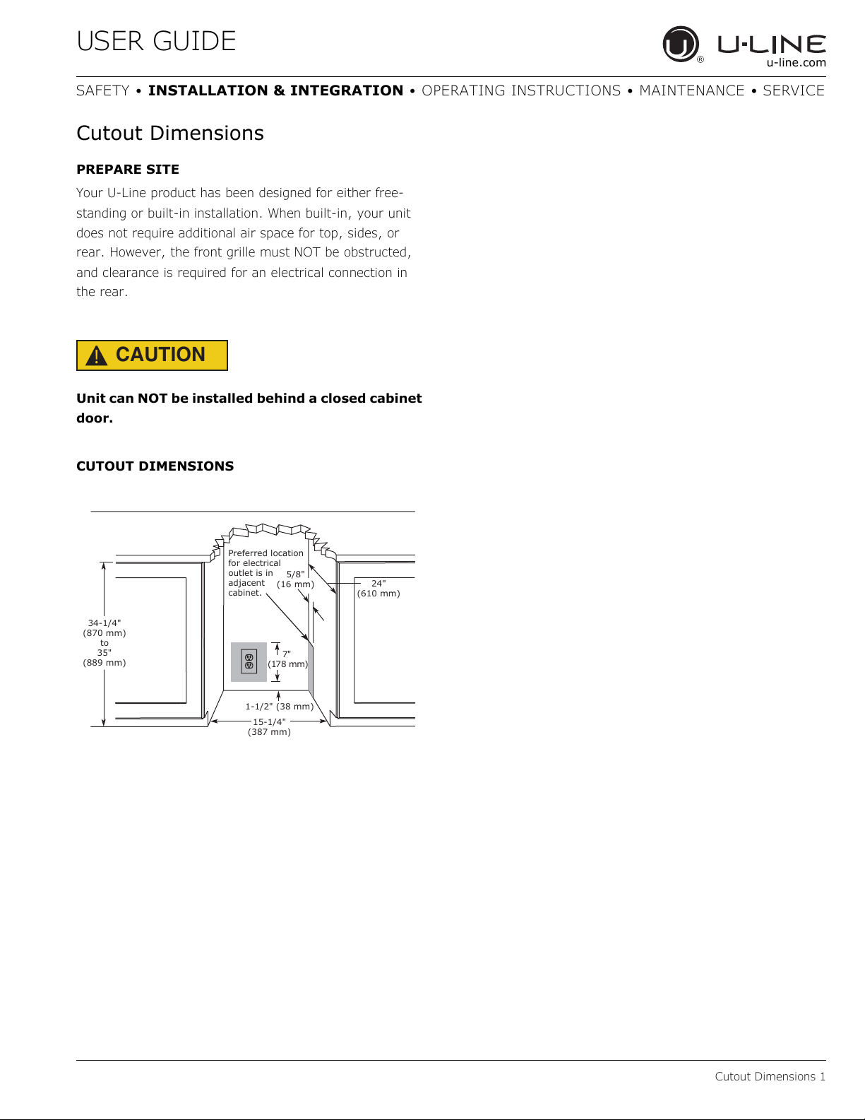
24"
(610 mm)
1-1/2" (38 mm)
15-1/4"
(387 mm)
34-1/4"
(870 mm)
to
35"
(889 mm)
Preferred location
for electrical
outlet is in
adjacent
cabinet.
7"
(178 mm)
5/8"
(16 mm)
u-line.com
SAFETY • INSTALLATION & INTEGRATION • OPERATING INSTRUCTIONS • MAINTENANCE • SERVICE
Cutout Dimensions
PREPARE SITE
Your U-Line product has been designed for either free-
standing or built-in installation. When built-in, your unit
does not require additional air space for top, sides, or
rear. However, the front grille must NOT be obstructed,
and clearance is required for an electrical connection in
the rear.
CAUTION
!
Unit can NOT be installed behind a closed cabinet
door.
CUTOUT DIMENSIONS
Cutout Dimensions 1
USER GUIDE
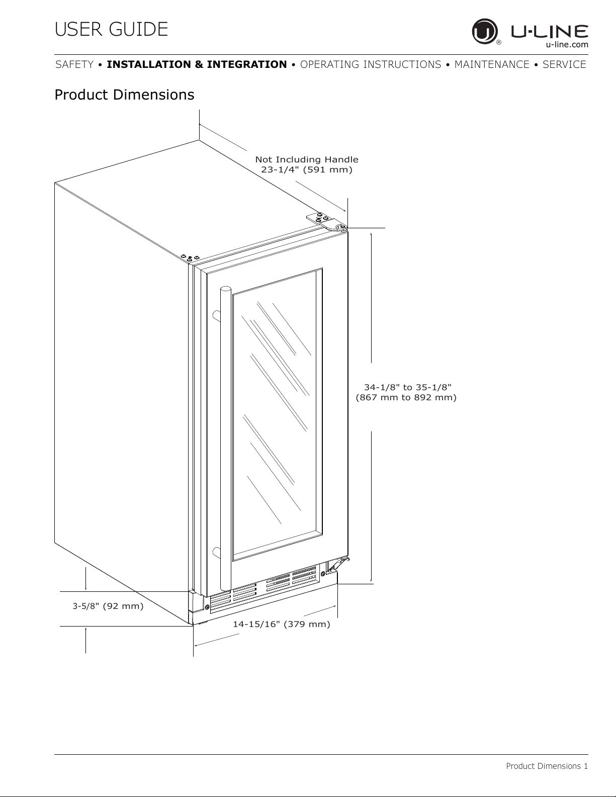
34-1/8" to 35-1/8"
(867 mm to 892 mm)
14-15/16" (379 mm)
3-5/8
" (92 mm)
Not Including Handle
23-1/4" (591 mm)
u-line.com
SAFETY • INSTALLATION & INTEGRATION • OPERATING INSTRUCTIONS • MAINTENANCE • SERVICE
Product Dimensions
Product Dimensions 1
USER GUIDE
u-line.com
SAFETY • INSTALLATION & INTEGRATION • OPERATING INSTRUCTIONS • MAINTENANCE • SERVICE
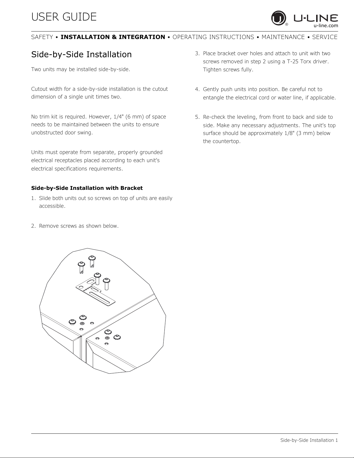
Side-by-Side Installation
Two units may be installed side-by-side.
Cutout width for a side-by-side installation is the cutout
dimension of a single unit times two.
No trim kit is required. However, 1/4" (6 mm) of space
needs to be maintained between the units to ensure
unobstructed door swing.
Units must operate from separate, properly grounded
electrical receptacles placed according to each unit’s
electrical specifications requirements.
Side-by-Side Installation with Bracket
1. Slide both units out so screws on top of units are easily
accessible.
3. Place bracket over holes and attach to unit with two
screws removed in step 2 using a T-25 Torx driver.
Tighten screws fully.
4. Gently push units into position. Be careful not to
entangle the electrical cord or water line, if applicable.
5. Re-check the leveling, from front to back and side to
side. Make any necessary adjustments. The unit’s top
surface should be approximately 1/8" (3 mm) below
the countertop.
2. Remove screws as shown below.
Side-by-Side Installation 1
USER GUIDE
u-line.com
SAFETY • INSTALLATION & INTEGRATION • OPERATING INSTRUCTIONS • MAINTENANCE • SERVICE
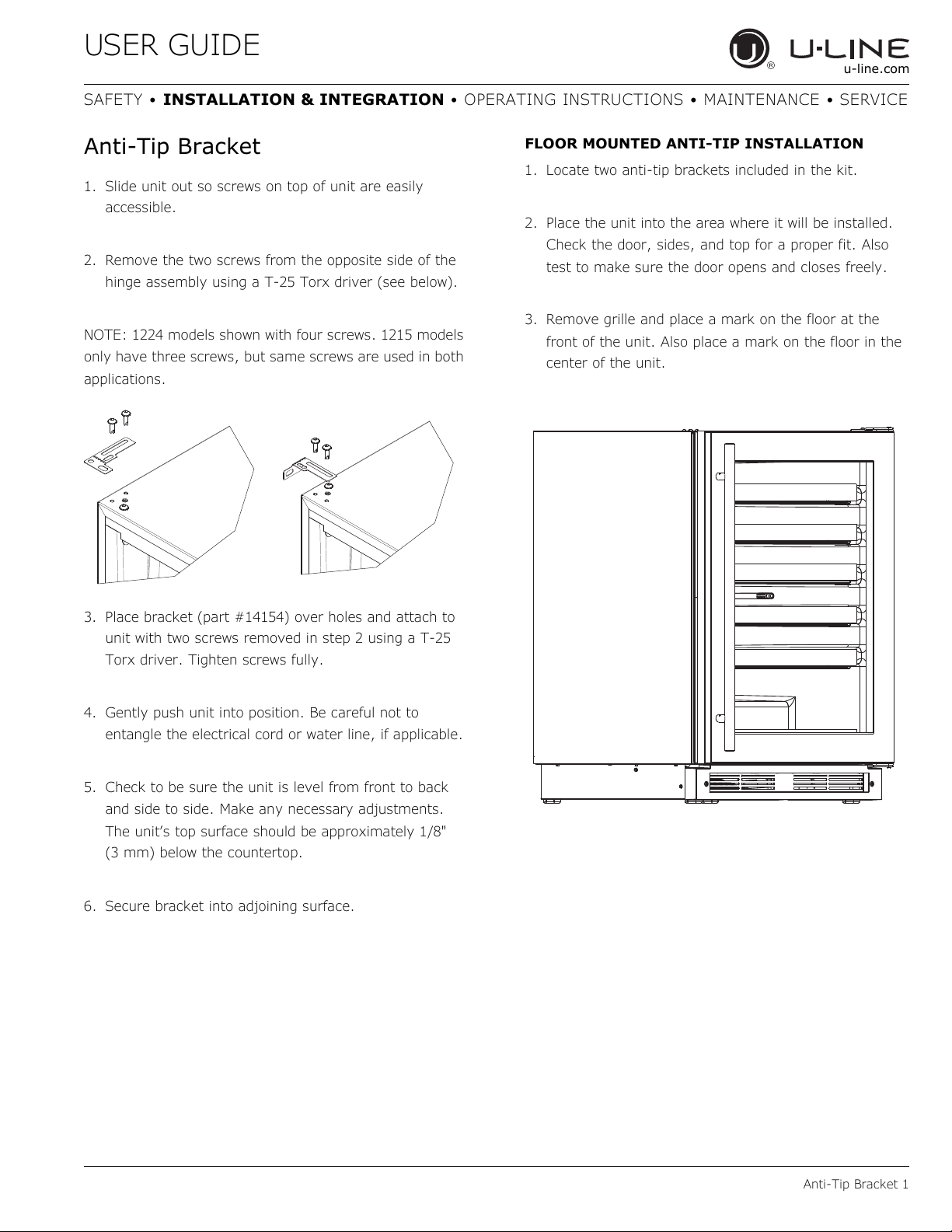
Anti-Tip Bracket
1. Slide unit out so screws on top of unit are easily
accessible.
2. Remove the two screws from the opposite side of the
hinge assembly using a T-25 Torx driver (see below).
NOTE: 1224 models shown with four screws. 1215 models
only have three screws, but same screws are used in both
applications.
FLOOR MOUNTED ANTI-TIP INSTALLATION
1. Locate two anti-tip brackets included in the kit.
2. Place the unit into the area where it will be installed.
Check the door, sides, and top for a proper fit. Also
test to make sure the door opens and closes freely.
3. Remove grille and place a mark on the floor at the
front of the unit. Also place a mark on the floor in the
center of the unit.
3. Place bracket (part #14154) over holes and attach to
unit with two screws removed in step 2 using a T-25
Torx driver. Tighten screws fully.
4. Gently push unit into position. Be careful not to
entangle the electrical cord or water line, if applicable.
5. Check to be sure the unit is level from front to back
and side to side. Make any necessary adjustments.
The unit’s top surface should be approximately 1/8"
(3 mm) below the countertop.
6. Secure bracket into adjoining surface.
Anti-Tip Bracket 1
USER GUIDE
C
L
Back wall
Back of unit
Front of unit
Surrounding
area (Top view)
A
A
B
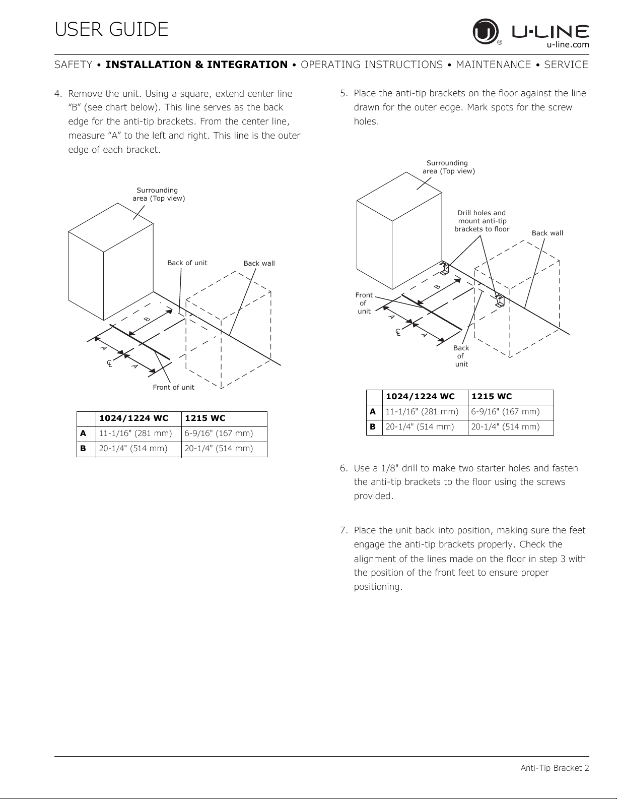
1024/1224 WC 1215 WC
A 11-1/16" (281 mm) 6-9/16" (167 mm)
B 20-1/4" (514 mm) 20-1/4" (514 mm)
1024/1224 WC 1215 WC
A 11-1/16" (281 mm) 6-9/16" (167 mm)
B 20-1/4" (514 mm) 20-1/4" (514 mm)
u-line.com
SAFETY • INSTALLATION & INTEGRATION • OPERATING INSTRUCTIONS • MAINTENANCE • SERVICE
4. Remove the unit. Using a square, extend center line
“B” (see chart below). This line serves as the back
edge for the anti-tip brackets. From the center line,
measure “A” to the left and right. This line is the outer
edge of each bracket.
5. Place the anti-tip brackets on the floor against the line
drawn for the outer edge. Mark spots for the screw
holes.
Surrounding
area (Top view)
Drill holes and
mount anti-tip
Front
of
unit
brackets to floor
B
A
C
A
L
Back
of
unit
Back wall
6. Use a 1/8" drill to make two starter holes and fasten
the anti-tip brackets to the floor using the screws
provided.
7. Place the unit back into position, making sure the feet
engage the anti-tip brackets properly. Check the
alignment of the lines made on the floor in step 3 with
the position of the front feet to ensure proper
positioning.
Anti-Tip Bracket 2
USER GUIDE
1
Turn to Adjust
u-line.com
SAFETY • INSTALLATION & INTEGRATION • OPERATING INSTRUCTIONS • MAINTENANCE • SERVICE
General Installation
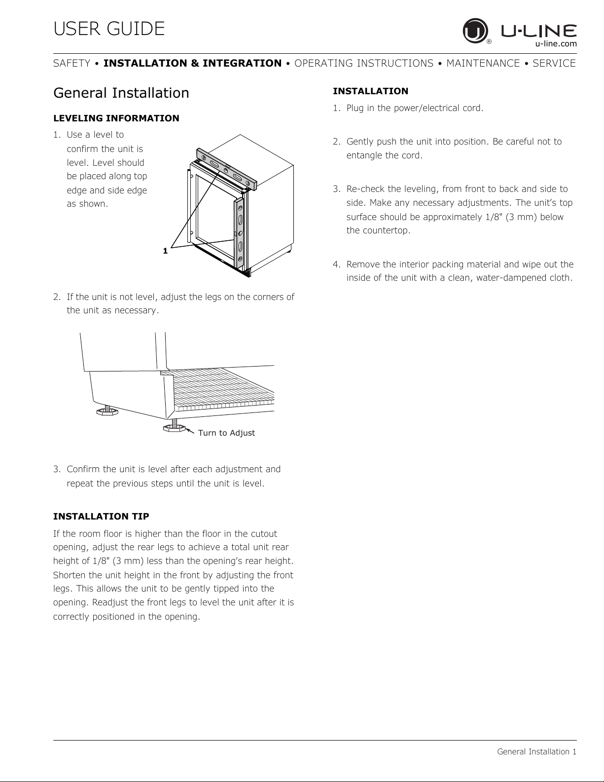
LEVELING INFORMATION
1. Use a level to
confirm the unit is
level. Level should
be placed along top
edge and side edge
as shown.
2. If the unit is not level, adjust the legs on the corners of
the unit as necessary.
INSTALLATION
1. Plug in the power/electrical cord.
2. Gently push the unit into position. Be careful not to
entangle the cord.
3. Re-check the leveling, from front to back and side to
side. Make any necessary adjustments. The unit’s top
surface should be approximately 1/8" (3 mm) below
the countertop.
4. Remove the interior packing material and wipe out the
inside of the unit with a clean, water-dampened cloth.
3. Confirm the unit is level after each adjustment and
repeat the previous steps until the unit is level.
INSTALLATION TIP
If the room floor is higher than the floor in the cutout
opening, adjust the rear legs to achieve a total unit rear
height of 1/8" (3 mm) less than the opening’s rear height.
Shorten the unit height in the front by adjusting the front
legs. This allows the unit to be gently tipped into the
opening. Readjust the front legs to level the unit after it is
correctly positioned in the opening.
General Installation 1
USER GUIDE
2
1
3
4
u-line.com
SAFETY • INSTALLATION & INTEGRATION • OPERATING INSTRUCTIONS • MAINTENANCE • SERVICE
Grille - Plinth Installation
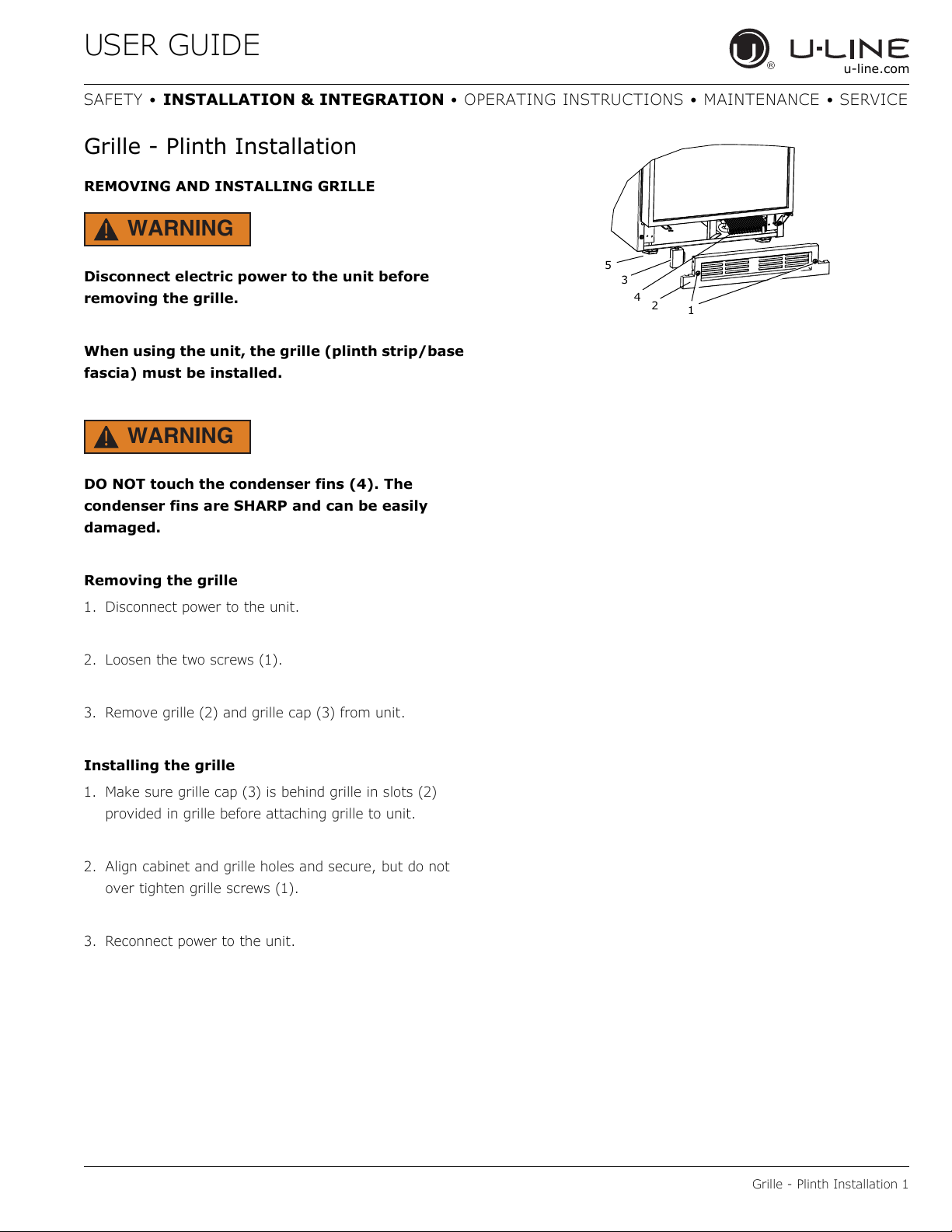
REMOVING AND INSTALLING GRILLE
WARNING
!
Disconnect electric power to the unit before
removing the grille.
When using the unit, the grille (plinth strip/base
fascia) must be installed.
WARNING
!
DO NOT touch the condenser fins (4). The
condenser fins are SHARP and can be easily
damaged.
Removing the grille
1. Disconnect power to the unit.
2. Loosen the two screws (1).
3. Remove grille (2) and grille cap (3) from unit.
5
Installing the grille
1. Make sure grille cap (3) is behind grille in slots (2)
provided in grille before attaching grille to unit.
2. Align cabinet and grille holes and secure, but do not
over tighten grille screws (1).
3. Reconnect power to the unit.
Grille - Plinth Installation 1
USER GUIDE
Wall Wall
90
Door Swing
90
Door Swing
2-1/8" Min.
(54 mm)
1/4" Min.
(6 mm)
u-line.com
SAFETY • INSTALLATION & INTEGRATION • OPERATING INSTRUCTIONS • MAINTENANCE • SERVICE
Door Swing
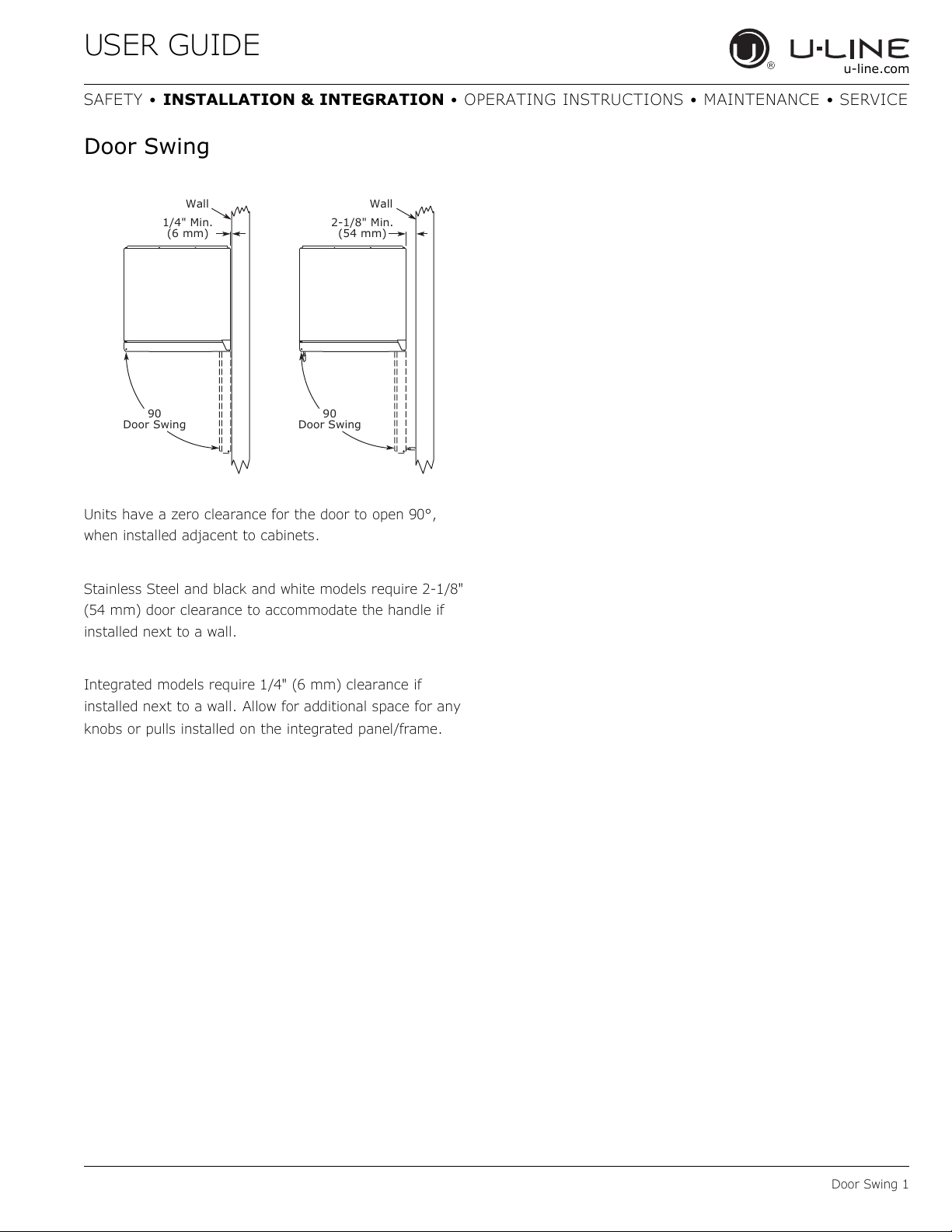
Units have a zero clearance for the door to open 90°,
when installed adjacent to cabinets.
Stainless Steel and black and white models require 2-1/8"
(54 mm) door clearance to accommodate the handle if
installed next to a wall.
Integrated models require 1/4" (6 mm) clearance if
installed next to a wall. Allow for additional space for any
knobs or pulls installed on the integrated panel/frame.
Door Swing 1
USER GUIDE
NOTICE
NOTICE
u-line.com
SAFETY • INSTALLATION & INTEGRATION • OPERATING INSTRUCTIONS • MAINTENANCE • SERVICE
Door Stop
Your U-Line unit was shipped to you with the optional
90° pin(s). (Models that are 15" wide include 1 pin. Models
that are 24" wide include 2 pins.) The unit’s door will open
freely without a fixed opening angle limitation. If you
would like the door stop at 90° follow these instructions.
The pin is designed to stop the door at 90° under
normal operating conditions. It is not designed
for excessive force. Do not use the door to move
the unit in/out of the cutout during installation.
If your unit is already undercounter, it might
need to be moved out/forward to access the
hinge.
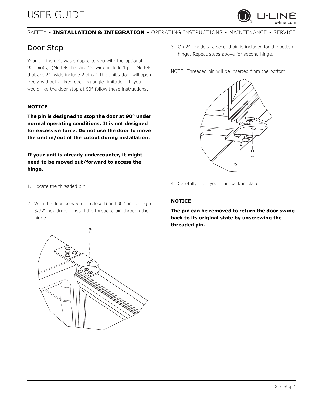
1. Locate the threaded pin.
3. On 24" models, a second pin is included for the bottom
hinge. Repeat steps above for second hinge.
NOTE: Threaded pin will be inserted from the bottom.
4. Carefully slide your unit back in place.
2. With the door between 0° (closed) and 90° and using a
3/32" hex driver, install the threaded pin through the
hinge.
The pin can be removed to return the door swing
back to its original state by unscrewing the
threaded pin.
Door Stop 1
USER GUIDE
NOTICE
u-line.com
SAFETY • INSTALLATION & INTEGRATION • OPERATING INSTRUCTIONS • MAINTENANCE • SERVICE
Door Adjustments
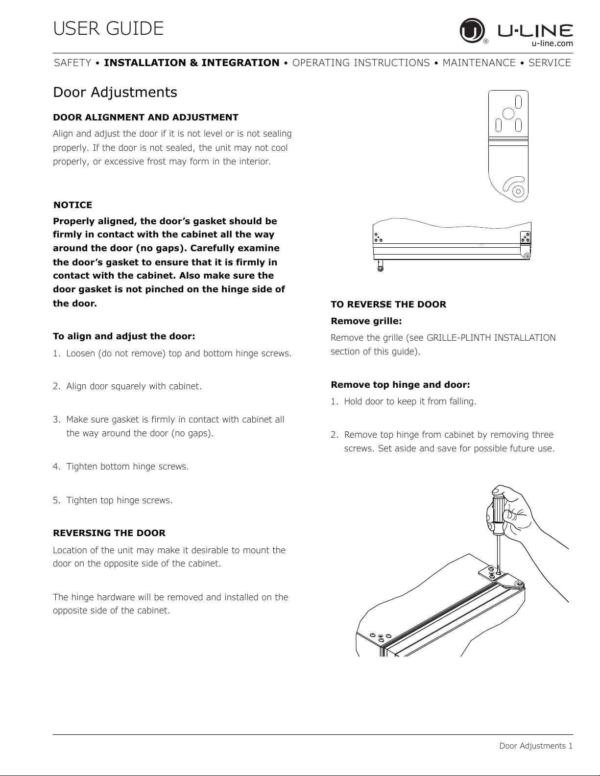
DOOR ALIGNMENT AND ADJUSTMENT
Align and adjust the door if it is not level or is not sealing
properly. If the door is not sealed, the unit may not cool
properly, or excessive frost may form in the interior.
Properly aligned, the door’s gasket should be
firmly in contact with the cabinet all the way
around the door (no gaps). Carefully examine
the door’s gasket to ensure that it is firmly in
contact with the cabinet. Also make sure the
door gasket is not pinched on the hinge side of
the door.
To align and adjust the door:
1. Loosen (do not remove) top and bottom hinge screws.
TO REVERSE THE DOOR
Remove grille:
Remove the grille (see GRILLE-PLINTH INSTALLATION
section of this guide).
2. Align door squarely with cabinet.
3. Make sure gasket is firmly in contact with cabinet all
the way around the door (no gaps).
4. Tighten bottom hinge screws.
5. Tighten top hinge screws.
REVERSING THE DOOR
Location of the unit may make it desirable to mount the
door on the opposite side of the cabinet.
The hinge hardware will be removed and installed on the
opposite side of the cabinet.
Remove top hinge and door:
1. Hold door to keep it from falling.
2. Remove top hinge from cabinet by removing three
screws. Set aside and save for possible future use.
Door Adjustments 1
 Loading...