

Page 1
Page 2

Page 3
User Guide
Ulead Systems, Inc.
September 2005
Page 4

First edition for Ulead® VideoGraphics Lab, September 2005.
2005 Ulead Systems, Inc.
All rights reserved. No part of this publication may be reproduced or transmitted in any form or by
any means, electronic or mechanical, including photocopying, recording, or storing in a retrieval
system, or translated into any language in any form without the express written permission of Ulead
Systems, Inc.
Software license
The software described in this document is furnished under a License Agreement which is included
with the product. This Agreement specifies the permitted and prohibited uses of the product.
Licenses and trademarks
All rights reserved. Ulead and the Ulead Systems logo are registered trademarks of Ulead Systems, Inc.
Intel, Pentium and MMX are registered trademarks and/or trademarks of Intel Corporation. Microsoft,
Windows, DirectX and/or other Microsoft products referenced herein are either trademarks or
registered trademarks of Microsoft Corporation. Adobe, the Adobe logo, and Acrobat are trademarks
of Adobe Systems Incorporated. QuickTime and the QuickTime logo are trademarks used under
license. QuickTime is registered in the U.S. and other countries. All other product names and any
registered and unregistered trademarks mentioned in this manual are used for identification purposes
only and remain the exclusive property of their respective owners.
Sample files
Files provided as samples on the program CD can be used for personal demonstrations, productions
and presentations. No rights are granted for commercial reproduction or redistribution of any sample
files.
North & South America
Ulead Systems Inc.
http://www.ulead.com
Support: http://www.ulead.com/tech
Japan
Ulead Systems Inc.
http://www.ulead.co.jp
Support: http://www.ulead.co.jp/tech
http://www.ulead.co.jp
E-mail: info@ulead.co.jp
Germany
Ulead Systems GmbH
http://www.ulead.de
Support: http://www.ulead.de/tech
International
Ulead Systems, Inc.
http://www.ulead.com
http://www.asiapac.ulead.com
http://www.ulead.com.tw
Support:
http://www.ulead.com/tech
http://www.asiapac.ulead.com/tech
http://www.ulead.com.tw/tech
China
Ulead Systems, Inc.
http://www.ulead.com.cn
Support: http://www.ulead.com.cn/tech
France
http://www.ulead.fr
Support: http://www.ulead.fr/tech
Page 5
Page 6

2
Contents
Chapter 1: Getting started ................................................. 3
Understanding the basics .................................................................................... 4
Working with the Filmstrip panel ......................................................................... 6
Viewing edit windows ......................................................................................... 15
Working with frames in a project ....................................................................... 17
Customizing Video Paint .................................................................................... 21
Chapter 2: Painting........................................................... 27
Working in different display modes .................................................................. 28
Making selections ............................................................................................... 32
Working with color .............................................................................................. 37
Using the Painting tools ..................................................................................... 41
Transforming selections .................................................................................... 46
Using the Clone tool........................................................................................... 47
Using the Retouch tool ...................................................................................... 48
Recording macros............................................................................................... 50
Applying filters .................................................................................................... 52
Previewing your work......................................................................................... 53
Shortcuts .......................................................................... 57
Index .................................................................................. 61
Page 7

3
Getting started
Video Paint is a powerful rotoscoping program that allows you to
paint directly over any frame in a video sequence. With Video
Paint, you can quickly and easily create special effects such as
lightning bolts, lasers beams, virtual sets and mattes. You can also
use the wide range of natural and particle-based painting tools to
work on single images for use in other projects, such as Web pages
and presentations.
Chapter 1
Page 8
VIDEOGRAPHICS LAB USER GUIDE
4
Understanding the basics
Video Paint allows you to select, draw, paint, and enhance each image that
makes up the frames of a video sequence. Each of the frames appears as a
clip in the Filmstrip panel. You can scroll through this panel to view the clip
or select a specific frame to work on. When you select a frame, it opens
automatically as an image in an edit window. Once an image is displayed in
an edit window, you can begin to work on it, paint or enhance it using
various Video Paint tools.
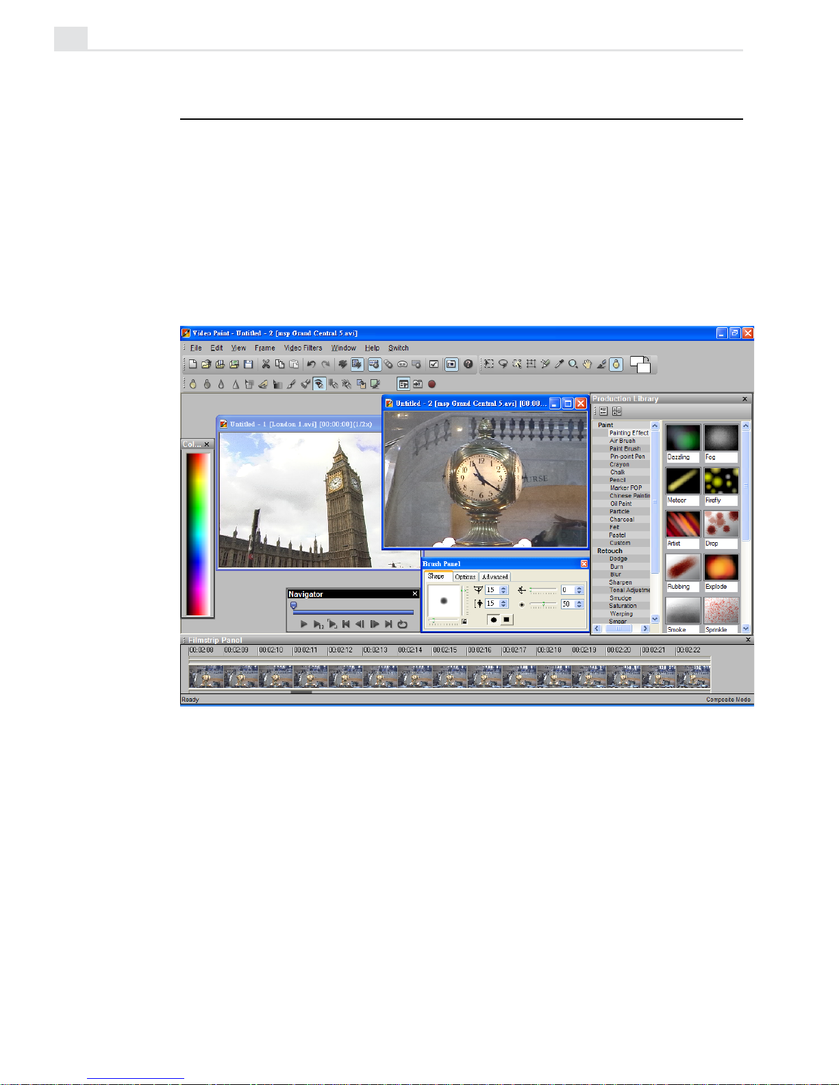
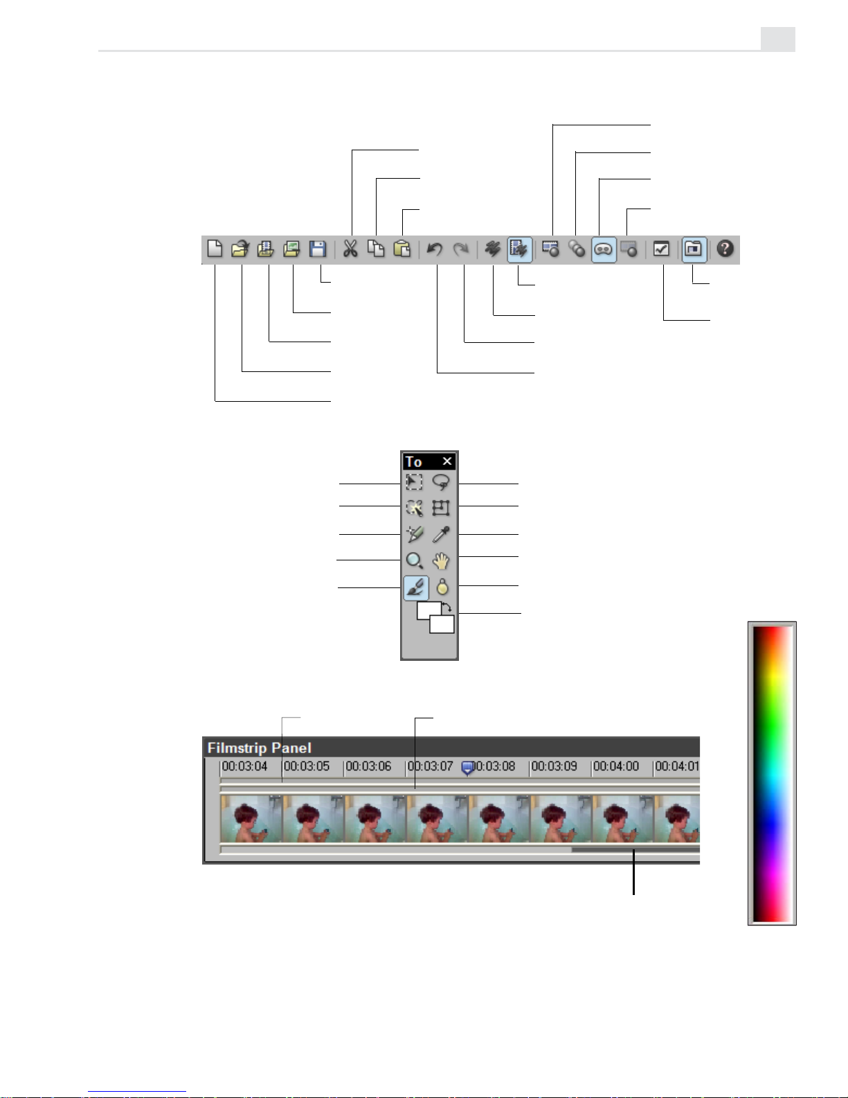
Video Paint's program window
Page 9
VIDEO PAINT: CHAPTER ONE
5
Standard toolbar
Filmstrip panel
Tool panel
Color palette
Save a Video
Paint project
Open an image
file
Open a video
file
Open a Video
Paint project
Create a new
Video Paint
project
Cut an
image
Copy an
image
Paste an
image
View in
Composite mode
View in Paint
Layer mode
Redo an undone
action
Undo a previous
action
View in Normal
mode
View in Onionskin
mode
View in Ruby Mask
mode
View in No Source
Video mode
Production
Library
Shape Selection tool
Magic Wand tool
Clone tool
Zoom tool
Painting tool
Foreground &
background color
Transform tool
Lasso tool
Grabber tool
Retouch tool
Eyedropper tool
Preview bar Cue bar
Preview options
Scroll bar
Page 10
VIDEOGRAPHICS LAB USER GUIDE
6
Working with the Filmstrip panel
The Filmstrip panel displays each frame of a clip in the Video Paint
workspace. At the bottom of the Filmstrip panel, there is a thin gray scroll
bar which indicates the current frames in view. By dragging on this gray
bar, you can scroll through these frames to see the entire contents of the
clip. When you have found a frame you are interested in, click on it to
display it in an edit window.
Note: You can also switch to the next or previous frame by using the Navigator or
pressing the [
CTRL+RIGHT] and [LEFT] arrow keys. To go to any cues, or the first or last
frames, press the [
CTRL+HOME] and [CTRL+END] keys.
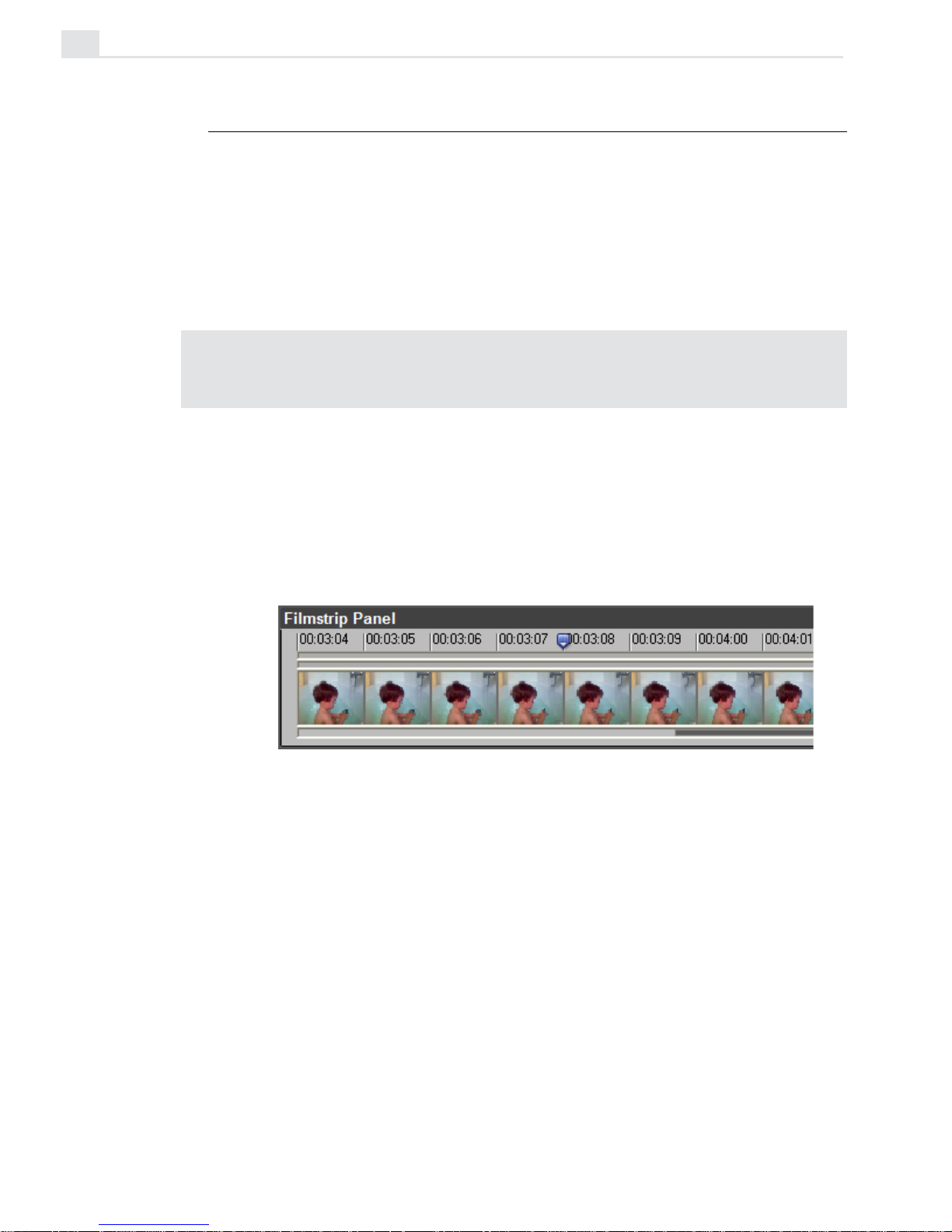
When you select a frame, blue place markers appear above and below the
Filmstrip panel indicating the frame’s position. (The markers are placed to
the left edge of the active frame.) The top marker indicates the frame’s
position (timecode) in the current view while the scroll bar indicates the
frame’s position relative to the entire clip.
Markers indicating the position of the current frame in view (top) and its
position relative to the entire clip (bottom)
Adjusting the view of the Filmstrip panel
You can change the frames currently displayed in the Filmstrip panel by
dragging the bottom scroll bar. Th length of the scroll bar differs depending on the number of frames in the clip and the current display unit. (The
display unit refers to how many frames appear within each division. For
example, at 5x each division represents five frames.) To change the display
unit, right-click over a frame in the Filmstrip panel and select a size from
Page 11
VIDEO PAINT: CHAPTER ONE
7
the Display Unit submenu. In the same menu, you can also define the size
of the thumbnails shown in the Filmstrip panel. Use a larger size if you are
at a higher resolution or have trouble seeing the frames clearly. (To view
more frames, float the panel and drag its borders to stretch it.)
Working with edit windows
When you work on an image in an edit window, you can choose to operate
in one of two modes: Composite or Paint Layer. Composite mode
allows you to select portions of an image (the source video) and then move
or manipulate them. Once moved or manipulated, the selection becomes a
floating selection area and moves up to the paint layer. By switching to the
Paint Layer mode, you can then work on these new selection areas just
as you would work on the video source image in Composite mode. Generally, you want to stay in Composite mode unless you need to edit specific
portions of the paint layer, such as removing areas of paint no longer
required in a frame.
Note: You can have any number of edit windows open at the same time, but only one
per clip in the Filmstrip panel.
Saving your work
In Video Paint, the video clip you are working on is referred to as a
project which you save as a special Ulead Video Paint file (UVP). UVP
files do not save the source video file, just the clip information which
contains a pointer to the original video file as well as a list of all the edits
performed on each frame in the video sequence. This serves to keep the
file size down and doesn’t force you to have to duplicate existing video
files. (When you open a UVP file, you need to ensure that the source file is
still present and in the same location. If not, a message box appears asking
you to browse for the file.)
Page 12
VIDEOGRAPHICS LAB USER GUIDE
8
Packaging a Video Paint project
While you can save your work as a UVP file, you may also want to occasionally package it with the File: Package command. This backs up the
original files, making them easier to transport as well as archive. Packaging
a file saves a project as a UVP file as well as the original video or image file
it references, moving or copying that file to a new location. This is
especially helpful if you plan on editing the project on another machine,
such as a laptop.
Note: To transfer a Video Paint project file and its source files to another PC, use
the same directory structure as the original to ensure the clips are correctly loaded.
Opening files into Video Paint
To get started in Video Paint, you need to open a file into the workspace.
You can open existing Video Paint, video or image files. When you open a
file, Video Paint allows you to select which frames in the file to open. This
ability to "partially edit" your work speeds up processing time, particularly
for larger files, as you don’t have to load the many hundreds of frames
that make up a video sequence. (The maximum duration for any file you
open is 30 seconds.)
Note: Video Paint automatically converts any file you open into its workspace to
True Color. If you want to constrain your editing to an indexed-color palette, then load
the palette into the Custom tab of the Color panel, see page 38.
Page 13

VIDEO PAINT: CHAPTER ONE
9
To open a video file:
1. Click the Open Video File button on the Standard toolbar or File:
Open - Video File to open the Open Video File dialog box.
2. Click the Duration button to open the Duration dialog box. In this dialog
box, you can preview the file as well as select which frames to open.
3. If you know the timecode for the frames you want to open, enter them in
the Mark-in and Mark-out spin boxes. If you do not know them, use
the Preview window’s control bar to play back the video; you can then
click the Mark-in and Mark-out buttons respectively to select the beginning and ending frames for the sequence you want to open.
4. Click OK. The dialog box closes and you return to the Open Video File
dialog box.
5. Click Open to place the file or selected frames into the workspace. The
first frame of the sequence automatically appears in an edit window.
Adjusting the number of open frames
If you have already opened a video or Video Paint project file and decided
that you only want to work on a specific number of frames within the clip,
click File: Edit Duration to select the frames you are interested in. Video
Paint saves the project (if changes have been made) and then reloads it, so
only the selected frames appear. (To edit frames outside of the current
project, use the File: Open command and select the frames in the Duration
dialog box.)
Note: If you want to work on each frame in a large video file, such as 30 seconds,
first open the entire file into Video Paint and then save it as a UVP file. You can then
use the Edit Duration dialog box to open specific frames without having to reopen
the original video file.
Page 14
VIDEOGRAPHICS LAB USER GUIDE
10
Starting a new Video Paint project
In Video Paint, you are not restricted to working only on existing video and
image files. You can create a new "empty" project which you can paint on
to create your own virtual set or background matte. Once finished, you
can insert the UVP file into Video Editor as part of a larger project.
To create a new Video Paint project:
1. Click the New button on the Standard toolbar or File: New [CTRL+N] to
open the New dialog box.
2. Specify the duration of the project in the Duration spin boxes as well
as its frame rate in the Frame rate combo box. You can choose from
the list in the drop-down menu or enter your own.
If the project is intended to be placed into Video Editor, make sure your
frame rate is equal to the frame rate of your Video Editor project.
Otherwise, you may get dropped or duplicated frames.
3. Select the frame size for the project using the options in the Frame
size group box. Again, if the project is destined for Video Editor then
the frame size should be identical to the Video Editor project.
4. Click OK. The dialog box closes and a new clip is created in the
workspace, with the first frame appearing in an edit window. The color
of these frames is determined by the current background color. To
change their color after creation, click Frame: Film Color.
Creating a video or image file
Once you have finished working on a Video Paint project, you can create a
new video or image file which merges your edits with the original source
file. To create a video file, click File: Create Video File. This opens the
standard Create Video File dialog box which has the same options as those
in Video Editor. If you plan on using your work in a Video Editor project,
insert the UVP file directly by selecting the UVP file type from the Files of
type combo box in the Insert Video File dialog box. If you first create a
video file and then insert it into Video Editor, you run the risk of reducing
Page 15
VIDEO PAINT: CHAPTER ONE
11
quality as the file undergoes compression twice, once in Video Paint and
once more when you create the final video sequence in Video Editor.
To create an image file, click File: Create Image File. This opens the
Create Image File dialog box which allows you to select the data type, file
format, resolution, and size of the image. If you plan on using the image in
other projects you are working on, make sure that the size is the same and,
if you have to compress the file, use a format with a lossless compression
scheme such as (TIF). Otherwise, use a standard format such as the
Windows bitmap (BMP).
Performing Cut and Copy operations
When working on your project, you will often want to copy changes you
have made in one frame to others in the video sequence. To do this, you
use the Cut and Copy buttons on the Standard toolbar or the Edit: Cut
and Copy commands. Copy duplicates a selected area or floating selection
while Cut removes it from the image. Once cut or copied, you can paste it
into the current frame or into another. When there is no selection area or
floating selection, Cut and Copy works over the entire image (in Composite
mode), or only edits (in Paint Layer mode.) If there are no edits, then the
commands work over the entire image.
Note: You can paste image data to and from Video Paint to any other image editor
such as Ulead PhotoImpact. If pasting to PhotoImpact, any mask information is
retained.
Page 16
VIDEOGRAPHICS LAB USER GUIDE
12
Performing a paste operation
Once the Clipboard contains an image, either from Video Paint or any other
image editor, you can paste it into an edit window. To do this, click the
Paste button on the Standard toolbar or Edit: Paste
[CTRL+V]. Images are
pasted at the same location they were cut or copied from. If the pasted
image was from a frame or other image larger than the active frame, then
the image is pasted at the top left corner of the current view.
Another option for pasting is the Edit: Paste - Selection Under Pointer
command. This pastes the image with the center of the image anchored to
your mouse pointer. Clicking anywhere within the edit window anchors the
image on that particular spot. The advantage of this command is that you
can position the pasted image without having to keep your finger on the
mouse button, providing greater freedom of movement.
Pasting masks
When you paste an image, it contains a selection area (mask) plus the
contents of the area itself (the image data). In Video Paint, you can choose
to paste only the mask without any image data by clicking Edit: Paste - As
Mask or Mask Under Pointer. After pasting, all you will see is the
selection marquee which now selects a portion of the active image. This is
useful if you wish to copy a selection area over multiple frames so that it
selects the same area each time.
Duplicating changes over frames
The Cut and Copy are useful for duplicating changes from one frame to
another. Often, however, you will want to duplicate changes over several
frames, even over several seconds. To do this, Video Paint provides the
Duplicate commands which work by duplicating your last edits. To
duplicate your edits to a new frame, first select the frame containing the
edits from the Filmstrip panel and then click either the Edit: Duplicate
Last Floating Selection [
CTRL+K] or Duplicate Last Paint Layer
[
CTRL+L]. Duplicate Last Floating Selection places a copy of the last
Page 17

VIDEO PAINT: CHAPTER ONE
13
active floating selection, while Duplicate Last Paint Layer copies every-
thing present in the last active paint layer.
To duplicate an action over several frames, you need to perform a power
duplication. Power duplication is much more flexible than the other
Duplicate commands as it allows you to not only specify how many frames
to duplicate over, but also the transparency for each duplication and
whether or not to add an effect to each duplicated portion. You can also
choose different start and end positions to have the duplicated portions
move over the entire sequence.
To perform a Power Duplication:
1. If not already selected, select the frame in the Filmstrip Panel with the
edits you want to duplicate.
2. Click Edit: Power Duplicate to open the Power Duplicate dialog box.
3. Select the source you want to duplicate from the Source group box.
The Selection option duplicates the currently active floating selection
or, if the selection is not floating, its mask, while Paint layer dupli-
cates the entire contents of the paint layer. (If you do not have a
floating selection active, then only Paint layer is enabled.)
4. Specify where you want the duplication to take place in the Apply
group box. You can choose to perform the duplication over frames
appearing before or after the active frame. In the Duration spin box,
indicate how many frames to duplicate over.
5. Set the Start and End frame transparency in the Start and End tabs.
(Default is 0, or no transparency.) You can also specify the X and Y
coordinates from where to place each duplicated edits. By having
different start and end coordinates, you can have the duplicated edits
appear to move linearly over time.
6. Specify an effect to apply to the duplicated edits in the Effect group
box. (Setting the duration of the duplication to one frame disables the
Effect options.)
Note: Effects are previously saved mask files that allow you to control which
areas of each frame are affected by the duplication as well as their intensity.
Page 18
VIDEOGRAPHICS LAB USER GUIDE
14
7. Click OK. The dialog box closes and the active floating selection or
paint layer is duplicated over the specified number of frames. If you
power duplicate over a number of frames, a message box may appear
indicating that the operation has exceeded the number of frames
specified in the Clear undo history for multiple frame actions
option in the General tab of the Preferences dialog box (see page 21).
If you select to continue, the duplication is performed but you will be
unable to undo its effect. If you want to retain Undo, increase the
number of frames in the Clear Undo history for multiple frame actions
option or decrease the number of frames to duplicate over.
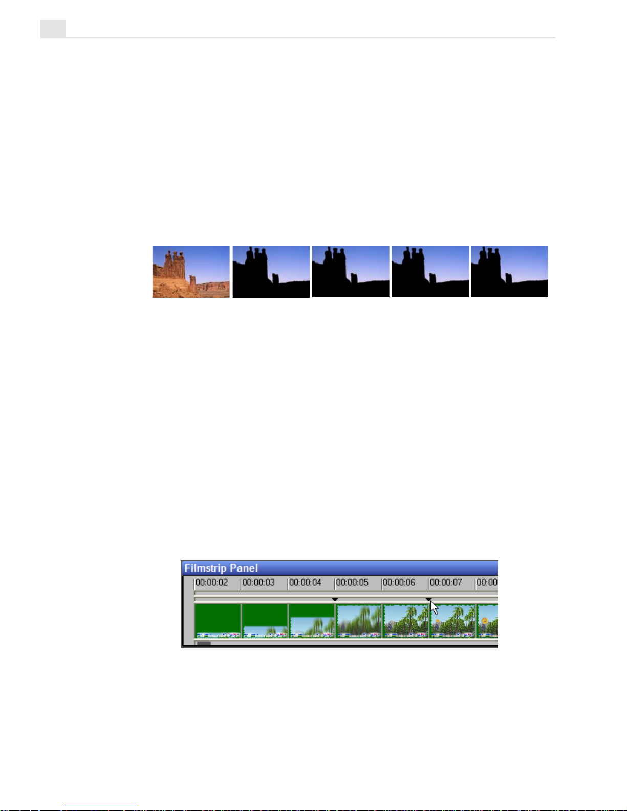
Creating a matte (frame 2) and then power duplicating it across the others
Placing cues
In Video Paint, you can place cues at any frame in a project to mark it for
later editing or identification. To place a cue, click the Cue bar (located
under the Preview bar of the ruler) at the appropriate location in the
Filmstrip panel; a black cue marker appears. The default name of the clip,
‘ &p’, uses the timecode of the cue’s location. For example, the default
name of a cue at the 12th frame would be ‘00:00:12’. To view a cue’s
name once it has been placed, double-click on it. If you wish to move a
cue, drag it along the Cue bar to a new location; to remove a cue drag it
off the edges of the Cue bar.
Cues placed at the 5th and 7th frames on the Filmstrip panel
Page 19
VIDEO PAINT: CHAPTER ONE
15
Managing project cues
To change the name of a cue, click View: Cue Manager. This opens the
Cue Manager dialog box which allows you to delete cues, rename them or
select specific ones to jump to. For renaming a cue, the Rename Cue dialog
box appears for you to type a name and description. To select a cue in the
Cue Manager dialog box, click the timecode displayed under the Frame
position button.
Note: To quickly rename a cue, double-click it to open the Rename Cue dialog box.
Viewing edit windows
Whenever you open a file, the first frame of the sequence appears in an
edit window at its original size (1x). Video Paint allows you to control the
size of this edit window as well as zoom in or out from the image. This
helps you to see more easily the areas you are editing as well as identify
areas for further enhancement.
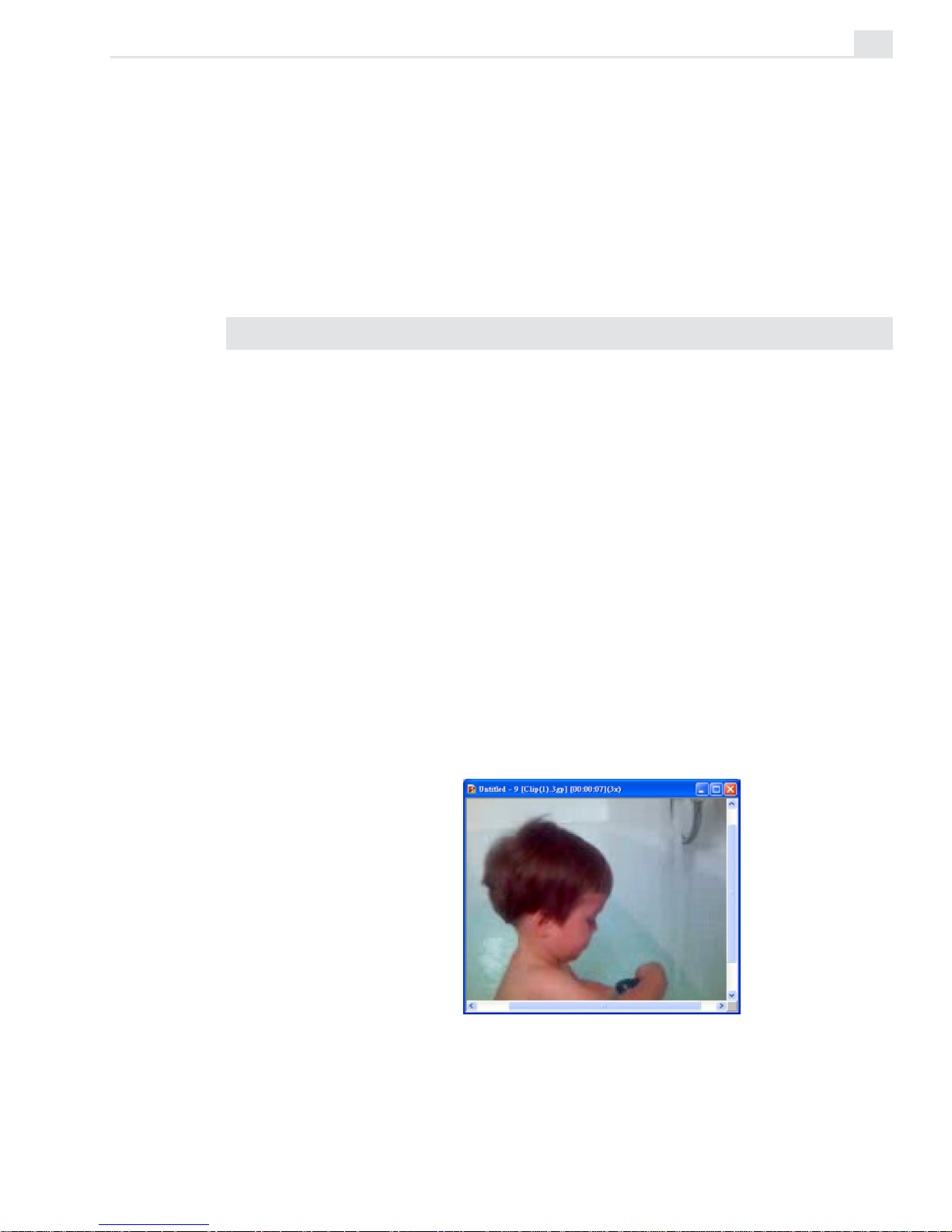
Zooming on an image
When you edit an image, you may want to see part of it in greater detail or
more of the image at a smaller size. You can do this using the View: Zoom
In and Zoom Out commands, the Zoom tool, and/or the Zoom quick
buttons on the Tool panel. You can view frames at any size from 1/16x to
16x the actual size.
Zooming in on an image to 3x
Page 20
VIDEOGRAPHICS LAB USER GUIDE
16
Using the Zoom tool
Use the Zoom tool when you want to zoom in on an image while at the
same time controlling which part of the image is displayed in the edit
window. To use the Zoom tool, select it and then click the area of the
image you want to see better. The image zooms in beneath your pointer’s
position. To zoom out, hold the
SHIFT key as you click. (You can also use
the Zoom slider on the Attribute toolbar to quickly zoom in and out on the
center of the image.) To focus on a specific area, you can drag over the
image, creating a rectangular viewing marquee, and when you release your
mouse, the image automatically zooms in on the area selected. (If the
viewing area is too large or the image is already at 16x magnification, the
view is not adjusted.)
Notes:
• You can also press the [+] and [-] keys to zoom in and out on images, regardless
of the current tool selected.
• Pressing the [
Z] key while using another tool automatically switches that tool to
the Zoom tool. Releasing the [
Z] key then switches the tool back.
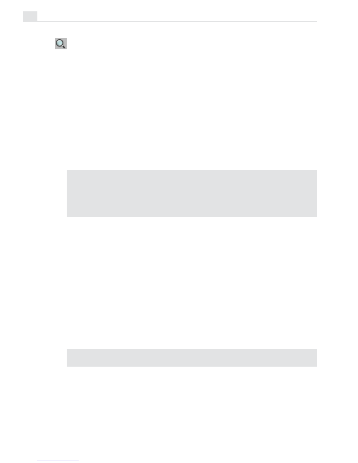
Using the Global Viewer
When an entire image cannot be displayed within the edit window, scroll
bars appear allowing you to navigate around the expanded image. The
Global Viewer provides an alternative to scrolling as it displays a thumbnail view of the entire active image. This thumbnail image contains a
floating frame that can be moved independently around the viewer. Moving
the frame automatically repositions the view of the image in the edit
window. To open the Global Viewer, click the box that appears at the
intersection of the scroll bars at the lower right corner of the edit window.
When you release your mouse, the Global Viewer disappears.
Note: To return the image to its original view (1x), click the 1:1 button on the
Attribute toolbar or View: Actual View.
Page 21
VIDEO PAINT: CHAPTER ONE
17
Using the Global Viewer to change views
Fitting an image in the edit window
When you use the Zoom commands, the image window does not change to
fit the new image size. Therefore, after zooming, the entire image may not
be displayed in the edit window and scroll bars appear along the window’s
edge. If you wish to display the complete image within the edit window,
choose one of the available Zoom commands from the View: Fit in
Window By submenu. (The maximum zoom level available is determined
by the size of the image and your current display mode.) An alternative to
the Fit in Window By command is the Fit in Window button on the
Attribute toolbar or View: Fit in Window. This automatically resizes the
image to fit within the edit window at the largest possible size without
introducing scroll bars.
Working with frames in a project
When you work on a project in Video Paint, you often need to control the
number of frames present as well as their content. The Frame menu
offers you several commands that allow you to manage frames as well as
control how frames are displayed in edit windows.
Page 22

VIDEOGRAPHICS LAB USER GUIDE
18
Inserting frames
There may be times when you need to extend the length of a video or
insert a new sequence into the middle of existing frames. Video Paint
allows you to do this by inserting frames. When you insert frames, you
increase the duration of the project by the number of frames you add. If
the project becomes too large, you may find that it slows down processing time. To avoid this, insert fewer frames or use the File: Edit Duration
command (see page 9) to make the project shorter.
To insert frames:
1. Select the frame in the Filmstrip panel where you want to begin insert-
ing the additional frames.
2. Click Frame: Insert to open the Insert Frame dialog box.
3. Specify the number of frames to insert in the Insert duration spin
box and then select either the Before current frame or After current
frame options to determine whether the inserted frames precede or
follow the active frame.
4. Specify the content of the new frames in the Link with group box.
The Empty frame option fills new frames with the film color while the
Source video option uses the frames from the source video file,
starting from the position specified in the Timecode spin box. (To
define this position, you can enter the timecode directly or move the
slider in the Preview group box; as you move, the timecode changes
accordingly.)
5. Click OK. The dialog box closes and the new frames are inserted at the
specified location.
Page 23

VIDEO PAINT: CHAPTER ONE
19
Duplicating frames
The Frame: Duplicate command is similar to the Insert command in that
it adds new frames to the clip in the Filmstrip panel. The difference is that
it fills the new frames with the same content of the frame currently
displayed in the edit window. When you click this command, the Duplicate
Frame dialog box opens allowing you to specify the number of frames you
want to duplicate. Once you click OK, the frames are duplicated after the
active frame, pushing any following frames to the right.
Deleting frames
The Frame: Delete command removes a frame or frames from your
project, shortening the duration accordingly. (This does not remove them
from the actual source file.) When you click this command, the Delete
Frame dialog box opens allowing you to specify which frames in the
sequence to remove. You can enter the timecode of the frames in the Start
and End spin boxes or use the Mark-In and Mark-Out buttons on the
Preview control bar.
Replacing frames
The Frame: Replace Source Video command allows you to replace the
content of a frame with that of another frame from the same source video,
or with an empty frame. For example, you could replace the image in frame
6 with the image in frame 32. This is particularly useful if you have
inserted a number of empty frames and wish to fill those frames with
others from the same clip, or replace the source video with an empty frame
before opening it in a Video Editor project.
Page 24

VIDEOGRAPHICS LAB USER GUIDE
20
To replace frames:
1. Select the frame in the Filmstrip panel where you want to begin your
replacement.
2. Click Frame: Replace Source Video to open the Replace Source Video
dialog box.
3. Specify the number of frames to replace in the Duration spin box and
then specify what to replace the frames with in the Link with group
box. The Empty frame option replaces the frames with the current
film color while the Source video option uses frames from the source
video file, starting from the position specified in the Timecode spin
box. Select the Only preview source video option if you do not want
the preview video to display any edits currently in the Paint layer.
4. Click OK. The dialog box closes and the following frames are replaced
with the specified content.
Page 25
VIDEO PAINT: CHAPTER ONE
21
Customizing Video Paint
The Preferences dialog box (opened by double-clicking the Status bar or
File: Preferences
[F6]) provides options for customizing certain aspects
of the program’s behavior. This is always a good place to start before you
do any editing as it helps optimize Video Paint for each project and adapts
the program to more closely match your work habits.
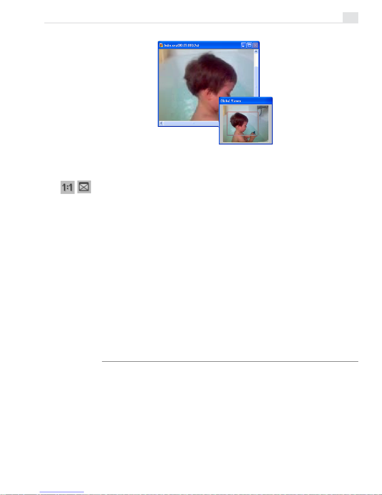
PREFERENCES DIALOG BOX: VIDEO PAINT TAB
1. Apply color filter controls how colors are displayed in Video Paint, based on the
NTSC or PAL color models. Select the appropriate option if you plan on having your
video played back over an NTSC or PAL device, such as a television. If you are
designing for monitor display only, leave this option clear.
2. Levels of undo/redo specifies the maximum levels of undo/redo allowed by
Video Paint (up to 99). As Video Paint allocates more memory for each level of
undo/redo, you may find that too high a level adversely affects performance. In
such cases, restrict the level to 3-4 only. You can, of course, choose not to have
undo/redo to maximize performance, but any editing performed is final.
3. Clear undo history for multiple frame actions clears the Undo history
whenever you attempt to perform an action that exceeds the number of frames in
the following Number of frames spin box. By clearing the Undo history, your
operations are carried out more quickly as memory does not need to be reserved
for undoing. However, if you clear the Undo history, you will be unable to undo any
previous actions. Leave this clear if you have enough system resources to handle
the memory demand for multiple actions.
1
2
3
4
5
6
7
Page 26
VIDEOGRAPHICS LAB USER GUIDE
22
4. Number of recently opened files specifies how many file names are stored in
the Recent History list found in the File menu.
5. Title safe area margin specifies the margin percentage for displaying any titles
in a video project. This is useful if you intend on sending your video out to video
tape or for broadcasting, as television has a different resolution than a computer
monitor and edges which are viewable on screen may disappear. As a guideline,
for NTSC devices choose 12%, PAL 10%. To view the title safe area marquee,
click View: Title Safe Area.
6. Return to original frame after playing returns any sequence to the first frame
after it has been played (like a CD player). When clear, the sequence stops on the
last frame after playing (like coming to the end of a tape in the VCR).
7. Play macro after recording plays a macro immediately after recording it. Leave
this clear if you are content with your macro recording or if you want to test it
yourself on another frame.
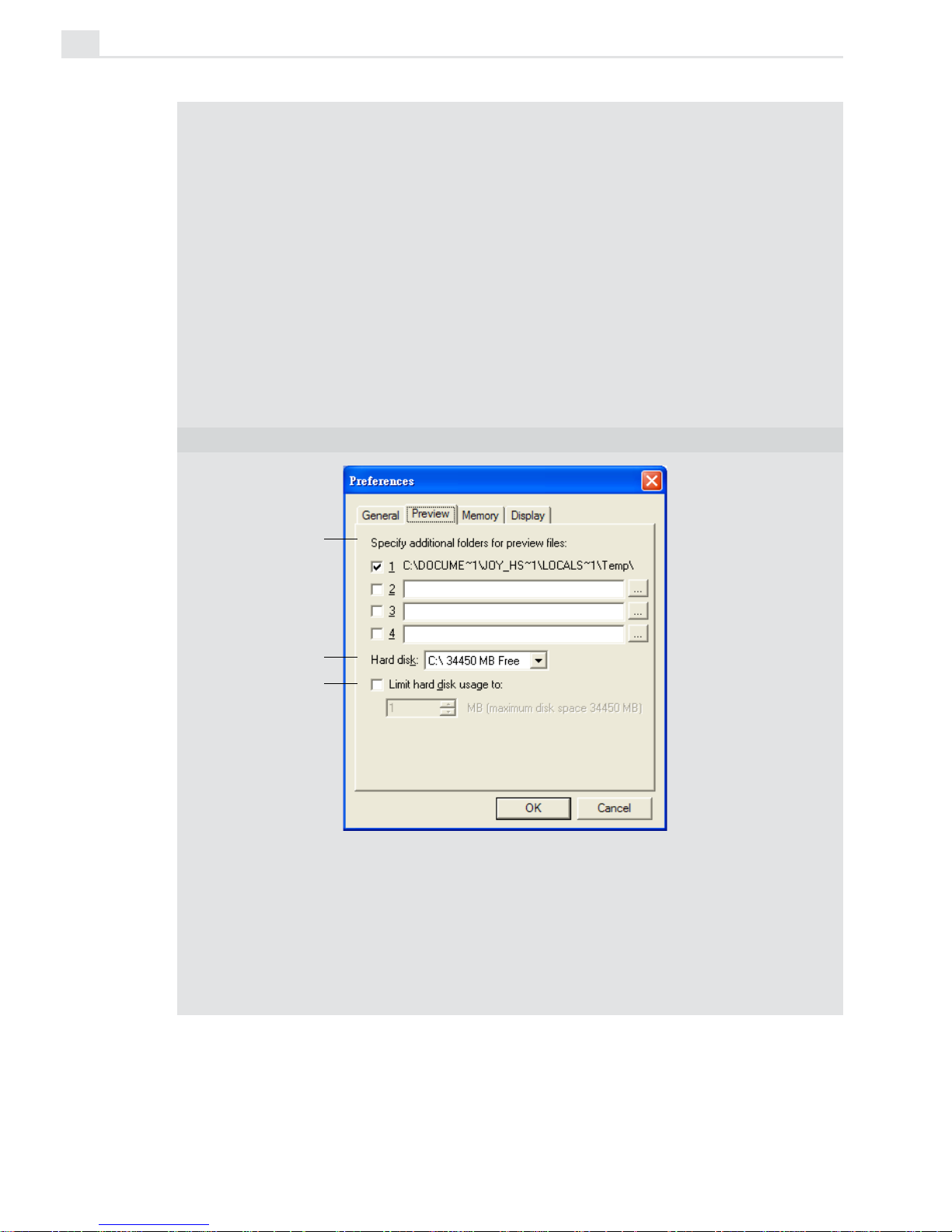
PREFERENCES DIALOG BOX: PREVIEW TAB
The Preview tab allows you to define additional memory space for creating preview
files only.
1. Specify additional folders for preview files indicates which folder Video Paint
can use to save preview files. The folder shown above is the folder specified in the
SET TEMP statement of your AUTOEXEC.BAT file. Specify other folders if you
have additional drives or a partitioned drive. If you only have one drive, leave the
other boxes empty.
1
2
3
Page 27
VIDEO PAINT: CHAPTER ONE
23
2. Hard disk displays how much free space you have on your hard drive.
3. Limit hard disk usage to specifies how much memory you want to allocate just
for Video Paint’s purposes. If you are only using Video Paint and want to optimize
performance, select the maximum amount possible. If you are using other
programs in the background you may want to limit this to about half. If left clear,
Video Paint uses your system’s memory management to control the use and
distribution of memory.
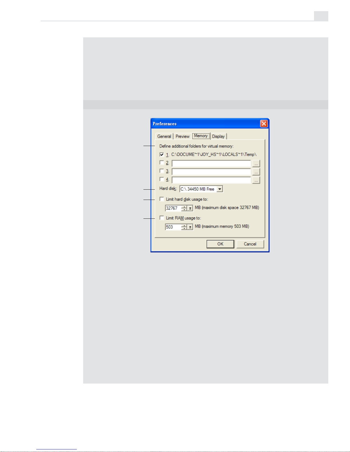
PREFERENCES DIALOG BOX: MEMORY TAB
The Memory tab gives you the opportunity to specify folders to provide additional
virtual memory when working with files. You can also determine how much total disk
space is allocated for virtual memory as well as how much space is allocated in RAM
for use by all programs.
1. Define additional folders for virtual memory allows you to specify the folder
used by the programs as additional working space. For example, when you don’t
have enough RAM, the programs can use extra memory from the hard disk (virtual
memory) as temporary RAM. The first folder shown in the Memory tab is the TEMP
folder defined by the SET TEMP statement in your AUTOEXEC.BAT file. If you
have more than one drive on your system, you can specify more than one temporary folder in the available entry boxes. If not, leave the entry boxes empty.
2. Hard disk indicates the space available on your hard disk. (The folder specified
in the Define additional folders for virtual memory section must be located
on this hard disk.)
3. Limit hard disk usage to allows you to specify how much memory you want to
1
2
3
4
Page 28
VIDEOGRAPHICS LAB USER GUIDE
24
allocate to the programs for use as virtual memory. If you want to run other
programs in the background, then choose about ½ the maximum amount. To use
Video Paint defaults, leave this option unchecked.
4. Limit RAM usage to allows you to specify how much memory you want to allocate
to the programs for use in RAM. If you want to run other programs in the background, then choose about ½ the maximum amount. To use Video Paint defaults,
leave this option unchecked.
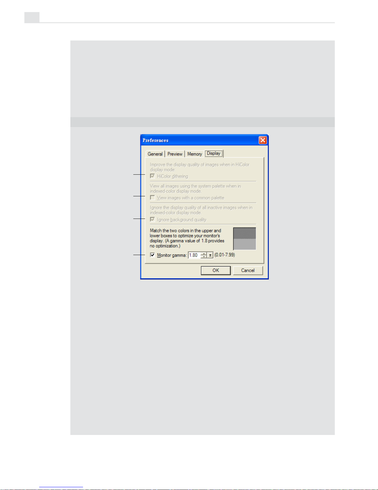
PREFERENCES DIALOG BOX: DISPLAY TAB
The Display tab allows you to modify the way images are displayed as well as
calibrate (adjust) your monitor. You should calibrate whenever you change monitor,
display adapters or the environment in which you work as lighting and temperature can
also affect a monitor’s performance.
1. Hi-Color dithering allows you to improve the display of True Color images when
you are in Hi-Color display mode.
2. View images with a common palette displays all images using the system
palette. This is only enabled when you are in 256-Color display mode and makes
your work more efficient as there is no need to repaint any of the images with a new
palette. This option is particularly useful when preparing CD-ROM based titles and
you need to see how images appear in 256-Color display modes.
3. Ignore background quality is enabled when in 256-Color display mode and
improves performance by not repainting any background images when you change
views. (Do not check this option if you need to identify background images.)
4. Monitor gamma allows you to calibrate your monitor for the optimum display of
images. Follow the procedure over to correctly calibrate your monitor.
1
2
3
4
Page 29

VIDEO PAINT: CHAPTER ONE
25
To calibrate your display:
1. Click File: Preferences to open the Preferences dialog box and click
on the Display tab.
At the bottom of the tab are two Grayscale squares. The top square is a
checkered pattern of black and white pixels, which when viewed from
a distance, looks 50% gray. The bottom square is 50% gray as your
monitor currently shows it. In a well calibrated monitor, both of these
squares should look approximately the same.
2. Examine the two color squares and if the two squares look different,
adjust the Monitor gamma spin box until the bottom square looks
similar to the top square.
The monitor gamma value can be any number from 0.01 to 7.99. If
none of the squares exactly match, try and estimate the best match. In
general, your value should fall within 0.8 – 2.4; if not, try adjusting the
brightness and contrast controls on your monitor.
3. Click OK. The dialog box closes and your monitor is now optimized for
displaying images in the program.
Page 30

VIDEOGRAPHICS LAB USER GUIDE
26
Page 31

27
Painting
Video Paint’s painting tools enable you to easily touch-up and
enhance any frame in your video project. The painting tools them-
selves present a variety of functions, from the advanced Retouch
and Clone tools to the more common Paintbrush and Transform
tools.
Chapter 2
Page 32

VIDEOGRAPHICS LAB USER GUIDE
28
Working in different display modes
In Video Paint, you can choose to view edit windows in a number of
different display modes. These modes make identifying your edits easier.
They also provide a means for creating mattes and animations. There are
four display modes to select from: Normal, Onionskin, Ruby Mask, and
No Source Video, each of which can be selected by clicking their respective buttons on the Standard toolbar or choosing their corresponding
commands in the View: Display Mode submenu.
Normal mode
Normal mode displays the contents of the active frame in the Filmstrip
panel. This mode is best when you wish to see the actual frame and select
parts of it, or to use it as a reference for performing various painting and
retouching tasks.
Ruby Mask mode
The Ruby Mask mode is useful when you want to create a video or image
matte that protects certain areas of an underlying video from any edits you
may perform. Mattes are often used in conjunction with Video Editor. A
good example of this is a "hold-out" matte that is used to remove the
matte-lines that often occur around objects which have been filmed on a
blue screen background.
Note: To apply the video matte, you must load it into Video Editor.
A Ruby Mask works by placing a semitransparent ruby colored layer over
an image. Whenever you paint on the image, you are actually removing the
mask, therefore revealing the underlying image. The advantage here is that
you do not see the color of the paint as you go, which makes it easier to
identify elements in the image to either cover or remove. When you change
modes, the removed area of the mask is filled with the current foreground
color.
Page 33

VIDEO PAINT: CHAPTER TWO
29
To create a video matte in Ruby Mask mode:
1. Select the first frame of the video you want to apply the matte over.
The frame appears as an image in the edit window.
2. Click the Ruby Mask mode button on the Standard toolbar or View:
Display Mode - Ruby Mask. A ruby film appears over the image.
3. Select a paint tool and define its attributes in the Brush panel (see page
42).
4. Start painting over the mask. The areas affected are removed from the
mask revealing the underlying image. If your painting removes too
much of the ruby mask, click the Erase button in the Shape tab of the
Brush panel. Now when you paint, the ruby mask is applied.
5. Select the next frame and click Edit: Duplicate Last Paint Layer.
(The paint layer from the previous frame is copied to the current
frame.) Once duplicated, you can start painting on it as in the previous
step.
6. Repeat steps 4 and 5 until the matte is complete. (If the object you are
creating the matte over does not move, then you only need to paint one
frame.)
7. Change display modes to see your changes and click the Save button
on the Standard toolbar or File: Save to save the project as a UVP file.
If you are going to apply the matte in Video Editor, you need to replace
the source video with a solid color so that you can better key out the
background and foreground.
Painting over an image in Ruby Mask mode
Page 34

VIDEOGRAPHICS LAB USER GUIDE
30
Onionskin mode
Onionskin mode is extremely useful when you are creating animations
and want to be able to see how your edits are progressing from frame to
frame. It works by placing transparent layers of each successive frame
you edit over its predecessors, allowing you to easily see your changes
from the previous frame as you work in the current frame.
To work in Onionskin mode:
1. Select the first frame of the video you want to paint over. The frame
appears as an image in the edit window.
2. Select a paint tool and define its attributes in the Brush Panel (see page
42).
3. Click the Onionskin mode button on the Standard toolbar or View:
Display Mode - Onionskin.
4. Click View: Onionskin Options to open the Onionskin Options dialog
box.
5. Select on which frames to apply the onionskin in the Overlay combo
box. Use Succeeding frames if you are editing frames to the right of the
active frame (toward the last frame), or Preceding frames if you are
editing frames to the left (toward the first frame).
6. Specify a value in the Number of frames spin box. The value you
enter here determines how many frames the onionskin layers appear
over. In most cases a value of 3-4 is sufficient to allow you to see the
path of your animation. If you lose your reference, you may want to
increase this or increase the Skin transparency to make your edits more
clear.
7. Define a transparency for each skin layer in the Skin transparency
spin box. This value indicates the transparency of the skin layer, and
not the edits you are performing. For example, a skin transparency of
30% produces a light result as it only allows 30% of the edit to show
through. The higher the value the more of the edit you can see. (Click
the Preview button to test how your changes affect any existing
onionskin layers.)
Page 35

VIDEO PAINT: CHAPTER TWO
31
8. Select the Show only paint layer option to have the onionskin applied
just to the paint layer. This speeds up processing time because only the
edited portions have a transparency applied. If left clear, the transparency is applied to the source video plus the paint layer. (Depending on
the type of video, this may produce no noticeable effect.)
9. Click OK. The dialog box closes and the settings take effect immedi-
ately.
Painting over frames in Onionskin mode
No Source Video mode
When working on an image, it can often get confusing trying to determine
where the image starts and the edits end. In such cases, you can remove the
image from view by selecting the No Source Video mode. No Source Video
mode removes the image from the edit window and replaces it with the
current background color. This allows you to easily see your edits in the
paint layer only. To view the frame’s image, change back to Normal mode.
Viewing an edit window with source video (left)
and without (right)
Page 36

VIDEOGRAPHICS LAB USER GUIDE
32
Making selections
In Video Paint, whenever you apply a command or use one of the painting
tools, it is applied over the entire image in the edit window. To restrict the
command or painting tool to a certain area of an image, you first need to
create a selection. To do this, Video Paint has three selection tools that
offer a wide range of options for creating both simple and more complex
selection areas. Once created, a selection marquee appears outlining the
selected area.
Note: In Paint Layer mode, the selection tools work by selecting the content of the
paint layer and not areas on the original image. (To do this, you need to be in
Composite mode.)
Understanding the selection marquee
When you create a selection, a dotted line appears around the edges of the
selected area. This dotted line is called the selection marquee. The
marquee can either be floating (containing image data) or non-floating,
(selecting the source video). Floating selections appear in the paint layer of
an image and are created whenever you:
• move a selection area,
• perform a transformation on a selection area,
• paste a selection into an image,
• click Edit: Select - Make Floating. (This command can also be
selected from the right-click pop-up menu.)
Hiding the selection marquee
Whenever you create a selection or make a floating selection, an animated
marquee appears indicating the selection border. This makes selections
easier to identify as well as move. If you find the marquee distracting, or
you prefer to see the entire selection as is, deselect the View: Show
Marquee command. The next time you create a selection or make a
floating selection, the marquee is not displayed.
Page 37

VIDEO PAINT: CHAPTER TWO
33
Selecting in the Composite and Paint Layer modes
If you are in Composite mode, any selection area you create selects
elements of the actual image. Moving this selection or manipulating it in any
way makes it a floating selection and moves it to the paint layer. Every
time you create a new floating selection, any pre-existing floating selections are merged with the paint layer. In Paint Layer mode, the selection
tools behave similarly to the way they do in Composite mode, except that
they allow you to select the content of the paint layer only. In this way,
you can more easily distinguish your edits from the underlying image and
then select them for copying to another frame for further editing.
Note: To make selection areas smoother, click the Anti-alias button on the
Attribute toolbar. The next time you make a selection area, the edges blend in
slightly with the surrounding background.
An added feature of selecting in the paint layer is the Shrink button on the
Attribute toolbar. When you select this button, any selection you make
‘snaps to’ the edges of your edits (as long as the edits are included in the
selection).
Selecting regularly shaped areas
The Shape tool allows you to select areas of an image based on a preset
size and/or shape, such as a square, rectangle, circle or an ellipse. To
determine the shape, click either the Rectangle or Ellipse buttons on the
Attribute toolbar. (To create a square or circular selection, make sure that
the Constraint button is selected.) To create a selection, drag your mouse
over the image. If you want the selection to always appear the same size,
click the Fixed Size button and enter the appropriate values in the neighboring spin boxes. The next time you click the image, a selection is made
based on the size you defined. Using a fixed size is useful when you need
to select same-size areas of an image, such as for a credit or title.
Page 38

VIDEOGRAPHICS LAB USER GUIDE
34
When you create a selection, it starts from where you first click your
mouse. This is fine in most cases, but sometimes you may want it to start
from the center, particularly if you are creating circular or square shapes.
To do this, first click the Draw From Center button on the Attribute
toolbar and then drag your mouse over the image starting from where you
want the center of the selection to be.
Selecting irregularly shaped areas
The Lasso tool allows you to select an area by drawing a freehand shape.
This is especially useful for selecting difficult areas, such as a person’s
head or objects with a number of different angles. It operates in two ways:
Dragging your mouse allows you to draw precise curved segments;
clicking your mouse allows you to define straight line segments. By
combining both drawing techniques, you can quickly outline selection
areas that contain both irregular and straight segments. When you have
finished outlining the selection area, double-click to release the Lasso and
Video Paint automatically selects all image data within the bounds of the
drawn selection area.
By checking the AutoSnap option on the Attribute toolbar, and then
entering a value into the Sensitivity entry box (up to 10), Video Paint can
help you quickly trace around irregularly shaped objects. The Sensitivity
attribute works by specifying the range of contrast values that are used to
define an object’s edge and AutoSnap pulls the selection area to that edge
as you draw. This works best when you are tracing a bright foreground
Creating a regular selection area
Page 39
VIDEO PAINT: CHAPTER TWO
35
object against a dull background. (If you find the selection "pulls" to
include unwanted areas, deselect the AutoSnap option or decrease the
sensitivity.)
Note: If you make a mistake while drawing a selection area or wish to start again,
press the [
ESC] key.
Selecting an area containing similar colors
The Magic Wand tool is useful when you want to select specific colors in
an image. When you click on an image, any colors that fall within the
values specified in the Similarity entry box are included in the selection
area. This is an effective way to select large solid colored portions of an
image, such as a blue screen or patches of skin and clothing.
When you use the Magic Wand tool, it operates in one of two modes,
Sample by Path or Sample by Area. In Sample by Path mode, dragging
your mouse over an image creates a line that calculates the largest and
smallest color values of the pixels under the line (any values entered in the
Similarity spin box are also included). Releasing your mouse then creates
the selection based on that range. Sample by Area mode works in much
the same way except that instead of taking the values of pixels under a line
it includes all pixels within a selected area. This mode works best for
irregular areas containing similar colors, such as backgrounds and gradients.
Creating an irregular selection area
Page 40

VIDEOGRAPHICS LAB USER GUIDE
36
Determining color similarity
When using the Similarity entry box, enter a value that you feel closely
reflects the range of colors you wish to select. To help determine the color
similarity range, move the Magic Wand over target pixels in the image and
notice the RGB color values displayed on the Status bar. Below is a
guideline on what to expect when choosing particular color ranges, (you
can only select a color range between 0 and 255):
• A value of 0 selects neighboring pixels with exactly the same color
value, such as all white.
• A value of 255 selects pixels of all colors, thereby selecting the entire
image.
• A value of 50 selects neighboring pixels that have values that differ from
the pixel you click on by 50. For example, if you click on a pixel with
values R25, G60, B190, neighboring pixels with values between R0,
G10, B140, and R75, G110, B240 are selected.
Adding to or subtracting from a selection area
Once you’ve created a selection area, you may discover that you left out a
portion of the image you wanted to include. To add to an already existing
selection area, press the [
A] key and use the selection tool as you would to
create a new selection area. The area you select is added to the rest of the
selection area. To subtract from a selection area, press the [
S] key and
select the part of the selection area you want to remove.
Creating a selection containing
similar colors
Page 41

VIDEO PAINT: CHAPTER TWO
37
Moving a selection area marquee (mask)
Sometimes you will want to use a selection area without moving the image
data it contains. For example, you may want to move a selection area to
expose certain portions of an image, or to protect other portions from any
effects or changes you may apply to the image. To do this, click the Move
Mask button on the Attribute toolbar or use the Grabber tool on the Tool
panel. Now, you can safely drag on the selection area without affecting the
composite image. (The Move Mask is only active if the selection is not
floating.)
Notes:
• Use the arrow keys on your keyboard to move a selection pixel by pixel.
• To move a selection marquee to another frame, first copy it and then click Edit:
Paste - As Mask, see page 12.
Working with color
Before you start painting on images, you need to select the color you wish
to apply. In Video Paint, you can do this in a number of ways, from
picking colors out of a palette to selecting colors directly from an image.
At any time, two colors are active – the foreground and background. You
can see these colors as color squares at the bottom of the Tool panel with
the lower right square representing the foreground color. This is the color
that is applied whenever you use a paint tool. The background color acts
as the default color which is used each time you create a new project. You
can quickly switch between the two by clicking the Switch arrow at the
top right of the two color squares.
Adding additional areas to a selection
Page 42

VIDEOGRAPHICS LAB USER GUIDE
38
Using the Color palette
The Color palette contains colors that you can apply to any image in the
edit window. The way colors are displayed in the palette varies according
to your selection in the View: Color palette submenu. You can display
palette colors in one of four methods: Map, Wash, Swatch, and Custom.
Which method you choose depends on the type of color you want as well
as which color picker you are more familiar with. To select a color, click it
with your mouse. The color then replaces the current foreground color. (If
you already know the RGB values of the color you want, you can enter
them directly in the appropriate RGB spin boxes.)
Note: When you run Video Paint for the first time, the Color palette is docked to the
program window in Compact mode and shows the colors of the default method. To
see all methods at the one time, deselect the View: Color Palette - Compact
command. The Color palette is floated and shows each of the methods as tabs in the
panel window. (This command can also be performed by holding down the [
CTRL] key
and right-clicking the Color Palette.)
Map Color Palette (left) and Wash Color Palette (right)
Swatch Color Palette (left) and Custom Color Palette (right)
Page 43
VIDEO PAINT: CHAPTER TWO
39
Selecting colors from the Color Picker pop-up menu
The Color Picker pop-up menu allows you to select a new color to
replace the selected color square, or to choose from a range of Color
Pickers. Each Color Picker provides a different method for selecting
colors, and each is suitable for particular situations. (You can open the
Color Picker menu by right-clicking over any color square in Video
Paint.)
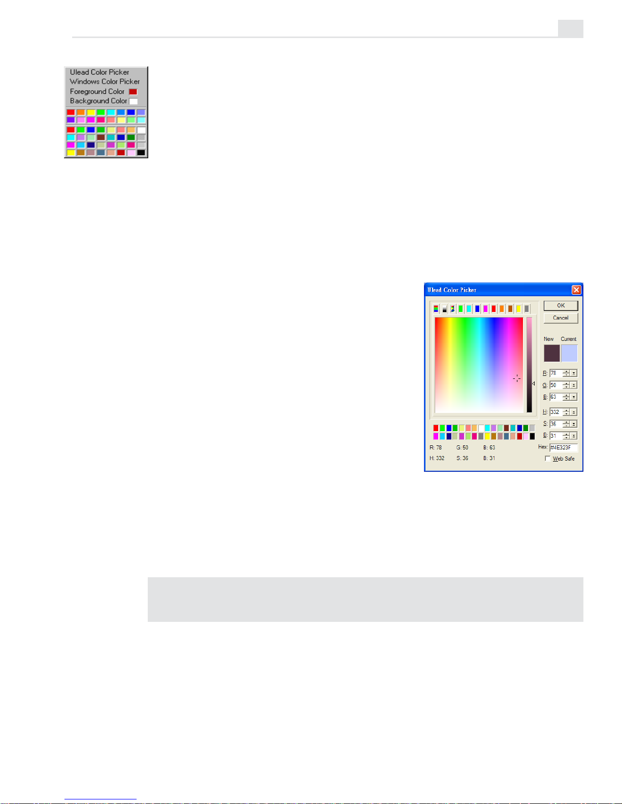
Using the Ulead Color Picker
Selecting the Ulead Color Picker command opens a dialog box which
displays a continuous color spectrum. The color spectrum shows hue, or
color, from top to bottom and luminance,
or the amount of brightness, from left to
right. When you move your mouse over
any colors, their respective RGB color
values are displayed at the bottom of the
dialog box and the color itself appears in the
left color square. If you click and hold
your mouse button over a color, a saturation bar appears and allows you to select a
specific color. Releasing your mouse
selects the color, subsequently displaying it
in the right color square.
For a more precise color selection, you can choose your color by clicking
one of the colored tabs above the color spectrum. This displays a range of
colors similar to the color on the selected tab. From here, you can select
the exact color by clicking the desired color cell.
Note: To select a particular color, enter its RGB values in the RGB spin boxes to
the right of the Color Picker window.
Page 44

VIDEOGRAPHICS LAB USER GUIDE
40
Using the Windows Color Picker
When you select the Windows Color Picker command, the standard
Windows Color dialog box appears from which you can select a basic or
custom color.
Selecting colors with the Eyedropper tool
The Eyedropper tool enables you to select a foreground color from colors
already in an image. As you move the Eyedropper over an image, the RGB
color values of the image are displayed in the Status bar and eventually
change to reflect the color changes from one pixel to the next. Clicking
your mouse selects the color under the pointer as the foreground color.
Note: To change which color square is active, click beneath either the foreground
and background squares on the Attribute toolbar. The next time you select a color,
the active color square changes.
Attribute toolbar of the Eyedropper tool
Loading and saving color tables
There may be times during your work that you find yourself continually
using the same colors with which to paint. You can store these colors as
color squares on the Attribute toolbar of the Eyedropper tool, or save
them as a color palette file (PAL) using the Custom tab of the Color
Palette. To do this, first change the color squares in the Custom tab to
those of the colors you regularly use and then click the Save button to
save the palette to its own file. (To change a color square, right-click it
and choose a color from the available color pickers or palette.) Once a
palette has been saved, you can bring it back into the Custom tab of the
Color Palette by clicking the Open button.
Page 45

VIDEO PAINT: CHAPTER TWO
41
Using the Painting tools
The Painting tools in Video Paint offer an extensive variety which allow
you to paint over an image using anything from a felt-tip pen to an oil
brush. When you use a paint tool, the paint is applied directly to the paint
layer and not the actual image itself. As such, you can work without fear
of damaging the original image as well as easily copy your work over
several frames.
To view the painting tools, click the Paint tool button on the Tool panel.
The Brush panel opens and all the various brushes are displayed along the
Attribute toolbar. To apply a paint tool, select the brush to use and then
click and drag over the areas of the image where you want the paint to
appear. For greater control over which areas are affected, select the area
and/or zoom into the image for a better view. (To paint over several
frames, see the "Duplicating changes over frames" section, page 12.)
Original image Paintbrush Airbrush Crayon
Charcoal Chalk Pencil Marker
Oil Paint Particle Drop Water Bristle
Page 46

VIDEOGRAPHICS LAB USER GUIDE
42
Specifying Brush panel attributes
When you choose a painting tool, the Brush panel displays the attributes
for that tool in four folders: Shape, Options, Color, and Advanced. The
current settings of these attributes are the same as they were when last
selected. If you change them, you can save the new settings to the Production Library by clicking the Save button on the Attribute toolbar. The Paint
Gallery of the Production Library also has a large number of paint brush
presets, such as specific types of art-pencils (2B, 6H), felt-tip pens and
effect brushes like fog and light. To use them as the current brush, doubleclick the thumbnail of the one you want or drag-and-drop it into an edit
window.
Note: The attributes explained below indicate all possible tool options. These vary
depending on the type of tool you are using.
BRUSH PANEL: SHAPE TAB
1. Height specifies the height of a brush. (You can also drag the vertical slider to the
right of the preview. To keep aspect ratio, click the Lock button.)
2. Width specifies the width of a brush. (You can also drag the horizontal slider at
the bottom of the preview. To keep aspect ratio, click the Lock button.)
3. Eraser Mode removes previously applied paint from the paint layer.
4. Elliptical Brush defines the shape of the brush head as elliptical. To use a
circular head, lock the width and height sliders.
5. Rectangular Brush defines the shape of the brush head as rectangular. To use a
square head, lock the width and height sliders.
Brush Angle defines the angle of the brush tip, from 0 (perpendicular to the image
surface) to 359 (the most extreme angle).
Soft edge adjusts the color blending along the brush’s edge, from 0 (no blending) to 100 (complete blending). The greater the soft edges, the slower your
painting takes effect because Video Paint has to calculate the appropriate amount
of blend with the underlying image.
1
2
3
4
5
Page 47

VIDEO PAINT: CHAPTER TWO
43
Weight defines how heavy the paint color is. The heavier the weight, the stronger
the impression it leaves.
Distribution defines the placement of the brush bristles. The higher the value,
the narrower the placement, while a lower value means a wider placement.
Random creates a random (although proportional) size variation among the
bristles of a brush. The value entered here defines the percentage of variance.
Bristle Thickness defines the thickness of each bristle in the paint brush. The
higher the number, the thicker each bristle and, as a consequence, the more paint
it can hold.
Density defines the number of bristles the paint brush contains. The more
bristles it contains, the more paint it can retain and thus the stronger the applied
color.
BRUSH PANEL: OPTIONS TAB
1. Apply method determines how paint is applied to an image. Depending on the
tool, you can choose one of the following:
• Always replaces the original colors with the painted color.
• Hue and Saturation applies only the hue and saturation values of the painted
color.
• Hue Only applies only the hue value of the painted color.
• Saturation Only applies only the saturation values of the painted color.
• Luminosity Only applies only the brightness and contrast values of the
painted color.
• If Lighter applies the painted color only if the painted color is lighter than the
background.
• If Darker applies the painted color only if the painted color is darker than the
background.
• Difference applies the color that is produced from the difference between the
values of the original colors and the painted color. For example, if the
underlying clip is R:10 G:210 B:125 and the overlaying clip is R:30 G:100
B:100 the resulting colors when merged are R:20 G:110 B:25 – (R:30-10 G:
210-100 B: 125-100.) (Values outside of 255 are taken as absolute values.)
1
2
3
4
Page 48

VIDEOGRAPHICS LAB USER GUIDE
44
• Addition applies the color that is produced from adding the color values of the
original colors with that of the painted color. For example, if the overlying frame
is R:10 G:210 B:125 and the underlaying clip is R:30 G:100 B:100 then the
resulting color will be R:40 G:255 B:225 – (R=10+30 G=210+100 B=125+100).
(Values greater than 255 are rounded down to 255.)
• Subtraction applies the color that is produced from subtracting the color
values of the original colors with that of the painted color. As in the above
example, R:10 G:210 B:125 and R:30 G:100 B:100 would result in the color R:0
G:110 B:25 – (R=10-30 G=210-100 B=125-100) (Color values less than 0 are
rounded down to 0.)
• Multiply applies the color that is produced from multiplying the color values
of the original colors with those of the painted color and then divides the result
by 255; rounding to the closest integer value for each color channel. For
example, if the overlying clip color is R:10 G:210 B:125 and the underlying clip
is R:30 G:100 B:100 the resulting color will be R:1 G:82 B:49 – (R=10*30/255
G:210*100/255 B:125*100/255.)
• Inverse of Multiply works in the same way as above except it inverts the
resulting color. For example, if the resulting color is black, the inverse will be
white.
• Pigment applies the color which is produced from blending the painted color
with the original colors, much in the same way an artist creates new colors by
mixing paints.
2. Freehand defines the drawing mode as Freehand. Freehand mode mimics
painting by hand, applying paint as you move your mouse.
3. Straight Line defines the drawing mode as Straight Line. Straight Line mode is
for painting straight lines. To paint a straight line, first click the point where you
want the line to start and drag to the point where you want it to end and release your
mouse. (Pressing the [
SHIFT] key constrains the line to an angle of 0º, 45º, or
90º.)
4. Connected Line defines the drawing mode as Single Line. This mode functions
much like the Straight Line mode except that after a line is painted, you can select
a new line segment and continue painting. Double-clicking then paints a straight
line connecting the ending point to the starting point.
Note: If you make a mistake while drawing a single or connected line, or wish to
start again, press the [
ESC] key.
Transparency defines how pure a color is. A transparency of 0 is pure color while
a transparency of 100 produces no color.
Wet Control defines how wet paint is when it’s applied, from 0 (the wettest) to
100 (the driest). The wetter the paint, the greater the amount of overflow.
Page 49

VIDEO PAINT: CHAPTER TWO
45
BRUSH PANEL: COLOR TAB
1. Single Color applies a single color as the brush paint.
2. Multiple Colors applies multiple colors as the brush paint. You choose which
colors from the neighboring Delta Hue, Delta Saturation, and Delta Brightness options. By controlling the value of these options, you determine how much
color is applied. For example, more hue introduces more color while an increase
in the saturation makes the colors appear stronger. When you paint, all the various
colors are then applied producing a rainbow-like effect.
BRUSH PANEL: ADVANCED TAB
1. Pressure options determine how paint is applied for tablet devices. If you do not
have a tablet device installed, these options are disabled.
2. Spacing determines how close each drop of color is applied as a percentage to
the current brush size. The higher the value, the farther away drops are applied.
Likewise, a lower value applies color closer together. For example, a value of 100
places each drop of color next to each other, creating a dotted line effect, whereas
a value of 300 places each drop of color at a distance 3 times the size of the
brush.
3. Fade-in/out mimics the consistency of paint on the specified brush type by
defining how quickly it fades out or in when a stroke is made. A higher number
equals a longer fade.
1
2
1
2
3
Note: The Brush Panel also shows the Texture tab when any of the painting tools
(except for the Particle and Drop Water tools) is selected. You can choose a preset
texture or load an image pattern and use it to paint over the frames in your clip.
Page 50

VIDEOGRAPHICS LAB USER GUIDE
46
Filling an area with color
Apart from painting over an image with a paint tool, you can also fill a
selection or the entire image with a solid color. To do this, click Edit: Fill
[CTRL+F]. This opens the Fill dialog box from which you can select the
color to use as the fill, the degree of transparency and the way the color is
applied, such as the hue only or just the difference. (For more on these,
see the description of the Options tab in the Brush panel, page 50). Once
you have applied the fill, you can perform many interesting effects, such as
filling an entire frame with white and then painting over it with a paintbrush
in the Erase mode. This removes the white from the paint layer, revealing
the underlying image. (This is a good technique for creating quick video
mattes.)
Transforming selections
After you’ve made a selection area, you can change its shape, size and
orientation using the Transform tool. When you click the Transform tool
button on the Tool panel, the Attribute toolbar changes to show each of the
possible transformation options. The first, Resize, allows you to drag
control points on the bounding box to distort the selection in several
directions. To spin the selection, click the Rotate Freely button or use
one of the other fixed rotation buttons like Rotate Counterclockwise or
Clockwise. You can also flip the selection horizontally or vertically using
the Flip Horizontally and Flip Vertically buttons.
Page 51

VIDEO PAINT: CHAPTER TWO
47
Using the Clone tool
The Clone tool is similar to the Paint tools except that it uses the image
for its color palette. For example, you can paint onto an image with another
part of the same image, or even from a second image in another edit
window. This is useful when you wish to replicate an object in an image,
such as creating dozens of fighter planes using one as the template, or if
you want to remove areas from the foreground and replace them with the
background, such as wires or props that were used during filming. When
using the Clone tool, you can also choose the type of paintbrush you want
to use from the Attribute toolbar. (To learn about cloning over several
frames, see the "Duplicating changes over frames" section, page 12.)
To use the Clone tool:
1. Click the Clone tool on the Tool panel to select it. The Attribute toolbar
displays the available tools you can use to paint with and the Brush
panel changes to show the available attributes for the selected tool.
2. Hold down the [SHIFT] key and click your mouse over the area you
wish to clone. This area is marked with a crosshair and the mouse
pointer changes to the clone pointer. (You can clone from the same
image or from another edit window.)
3. Move to the area on the image where you want the clone to appear and
start dragging your mouse. The crosshair changes to indicate the area
you are cloning and as you paint you replace the area with whatever the
crosshair passes over. (The size and shape of the area painted are
determined by the current attributes in the Brush panel.)
In the Options tab of the brush panel, you can specify how the cloning
point behaves as you paint with the Absolute, Frame, and Relative
options. Absolute is the default mode and paints whatever the clone
crosshair passes over. Whenever you release your mouse the crosshair
returns to its original position allowing you to clone the same feature
again. Relative allows you to clone continuously, retaining a relationship with the clone crosshair regardless of where you place your
mouse. (The clone crosshair does not return to the original location
Page 52

VIDEOGRAPHICS LAB USER GUIDE
48
when you release the mouse.) This is useful if you are cloning large
areas and often release your mouse and do not want to start from the
beginning point. Frame is for cloning between different frames on the
same clip. (To do this, first insert the file again so you now have two
copies in the workspace.) Whenever you paint the contents on the
target frame, these portions are replaced with whatever is in the edit
window you are cloning from and is most useful for cloning areas
successively over several frames. (When you choose Frame, the clone
crosshair appears in the top left corner of the image and as you clone
the crosshair moves to the exact same location to ensure you are
cloning accurately between both the active and target frames.)
Cloning an image from a second edit window to another
Using the Retouch tool
The Retouch tools are not strictly painting tools in the sense that they do
not paint over an image with a selected color. Instead, they are used to
touch-up areas of an image to either enhance them, remove errors or
perform special effects, such as smudging and warping. When you apply a
Retouch tool, the tool uses the shape and size of the current brush each
time you click your mouse. To perform the effect over a larger area, drag
your mouse or increase the size of your brush. To reapply and increase the
effect on a specific area, click repeatedly. (Smudging requires you to drag
the tool as it smudges color from one area into another.)
To view the retouching tools, click the Retouch tool button on the Tool
panel. The Brush panel opens and all the retouch tools are displayed along
the Attribute toolbar. The attributes for these tools are identical to the Paint
tools (see page 41) except the Options tab, which changes to display
controls for refining the degree of retouching.
Page 53

VIDEO PAINT: CHAPTER TWO
49
(To learn about cloning over several frames, see the "Duplicating changes
over frames" section, page 12.)
Notes:
• Confine the area to retouch by first creating a selection area.
• You need to be in Composite mode before you can start using a Retouch tool.
Once you have edited an image, you can switch to Paint Layer mode to work on
just that area.
Original Colorize Pen Dodge Burn
Blur Sharpen Tonal Adjustment Smudge
Saturation Warping Smear Remove Scratch
Remove Noise Color Transform Pen Remove Red Eye
Page 54

VIDEOGRAPHICS LAB USER GUIDE
50
BRUSH PANEL: OPTIONS TAB (RETOUCH TOOL)
Dodge increases the amount of luminosity in an image, making areas lighter.
Burn reduces the amount of luminosity in an image, making areas darker.
Blur blurs the edges of an image making them less distinct.
Sharpen sharpens the edges of an image thereby making them more distinct.
Tonal adjustment controls the amount of highlight, midtone, and shadow in an
image. Highlight works by adjusting the whitest or brightest parts of an image,
while Midtone adjusts the colors that fall between the dark and light areas of an
image. Shadow works by adjusting the blackest or darkest parts of an image.
Smudge smears the colors in an image as you drag your mouse.
Saturation adds more intensity to colors, making them appear stronger. Clicking
the Desaturation button removes intensity from colors, making them lighter.
Warping distorts an image as you drag your mouse.
Transparency determines the transparency of the paint as it is applied.
Wet adds water to the paint, making it blend more smoothly with the colors of an
image.
Dry removes water from the paint, making it appear more distinct from the colors
of an image.
Smear controls the amount of paint overrun.
Note: The available attributes for each brush that can be modified in the Options tab
vary depending on the currently selected Retouch tool.
Recording macros
Macros give you the ability to record specific brush strokes made with
either the Paint or Retouch tools and use the exact same stroke order again
on future frames. Macros can make common, repetitive editing tasks go
much faster and far more easily as well as create "on-the-fly" animations.
When you create a macro, it is stored in the Production Library and when
you apply it, you have a number of options to control how it plays itself
back over each frame in a video sequence.
Page 55

VIDEO PAINT: CHAPTER TWO
51
To record a macro:
1. Click the Macro button on the Attribute toolbar (for Paint and Retouch
tools only). A message box appears preparing for recording.
Note: When you record a macro, Video Paint clears the previous Undo history to
help free up system resources. If you want to retain any previous edits, first save
the file before recording.
2. Click OK. Video Paint centers the edit window and you can start
painting on the image.
You can paint as slowly as you like, changing tools and attributes as you
go. You can also undo any actions which are ignored when you play the
macro back.
3. When finished, click the Macro button again to end the recording. The
Add To Library dialog box opens.
4. Select the folder in the Macro gallery where you want to store the
macro and then enter a name for the macro in the entry line below the
thumbnail image as well as a brief description in the Annotation box.
5. Click OK. The macro is now saved to the Production Library and the
edits removed from the edit window. (For applying a macro, see the
following procedure.) If you have selected the Play macro after
recording option in the Preferences dialog box (see page 21, the Macro
Playing Options dialog box opens allowing you to specify how you
want the macro to be applied.
Page 56

VIDEOGRAPHICS LAB USER GUIDE
52
To play back a macro:
1. Select the frame from where you want the macro to begin its playback.
2. Click the Production Library button on the Standard toolbar and locate
the macro in the Macro gallery that you want to play back.
3. Double-click on the thumbnail of the macro you want to play back or
drag-and-drop it into the edit window to open the Macro Playing
Options dialog box.
4. Specify how many frames to play the macro back over in the Number of
frames spin box.
5. Specify how the macro should play back in the Playing method group
box. Select Entire image if you want the macro to appear the same on
each frame. To have the macro animate sequentially over each frame,
click either the Progressive or Regressive options. Progressive starts
the playback of the macro from the first stroke of the macro to the last,
while Regressive starts from the last stroke to the first. If you want to
determine where the macro should start playing back from (other than
the top left corner of the edit window), select the Manually place top
left corner in frame option.
6. Click OK. The macro begins playing back according to your settings. If
you selected the Manually place top left corner in frame option, you
need to click in the edit window image from where you want to start
play back.
Playing back a macro progressively
Applying filters
The video filters in Video Paint are the same as those found in Video Editor
and can be used from the Menu bar or from the Video Filter gallery in the
Production Library. While they are the same in design, they do, however,
Page 57

VIDEO PAINT: CHAPTER TWO
53
differ in application. For example, in Video Paint, the filters are applied
immediately to the frames in the clip, or to any frames included in the
preview area, and the rendered result appears in the Paint Layer which you
can then edit or paint over accordingly. (In Video Editor, they are applied to
the clip only and are not rendered until you create or preview the file.)
Because filters in Video Paint are rendered, you may find that they take
longer to apply, depending on your system resources or the type of filter.
To apply a video filter:
1. Drag over the Preview bar in the Filmstrip panel to select the frames
you want to apply the filter to. (If you want to apply the filter to the
entire clip, make no selection.)
2. Select the Video Filter gallery from the Production Library and locate
the filter you want to apply from one of the available folders. (You can
also select the filter by going directly to its command in the Video
Filters menu.)
3. Drag-and-drop the filter you want to apply onto the edit window to
open the filter’s dialog box. (By double-clicking on the filter’s thumbnail, you can see a preview of the type of filter and its options.)
4. Adjust the settings of the filter as well as define any key frames and
click OK. The filter is then applied to the active clip.
Applying a Whirlpool video filter
Previewing your work
When working in Video Paint, it is a good idea to regularly preview your
work to see how your project is developing. You can do this in one of two
ways – by creating a preview file or by flicking through a series of
frames. Previewing works in much the same way as in Video Editor while
flicking works by displaying a series of frames quickly, much like flipping
through the pages of an animation.
Page 58

VIDEOGRAPHICS LAB USER GUIDE
54
Performing a flick preview
Performing a flick preview is a simple process of selecting the frame
from where you want the preview to begin and then clicking the Flick
Preview button on the Navigator or View: Flick
[SHIFT+F]. The preview is
then performed on the image in the edit window. Before you perform the
preview, however, you need to set your flick options to determine which
area of the image is previewed as well as how many frames to flick
through.
Performing a flick preview
To set your flick options:
1. Click View: Flick Options to open the Flick Options dialog box.
2. Specify the number of frames to flick through in the Backward and
Forward spin boxes. The number you specify determines how many
frames are previewed when you perform a flick. Backward frames are
flicked first followed by forward frames. You may want to have a few
backward frames included in the flick to give you a reference as to
what occurs before the flick reaches your edited frames.
3. Select the speed to perform the flick at using the Speed group box.
4. Specify the area on the frame you want to flick through using the Flick
area spin boxes or by dragging the control points in the bounding box
in the preview image. (To move the bounding box on the Preview
image, place your pointer in the center and drag.)
When flicking through a specific area on the frame, it is a good idea to
select the Show border option because it places a thin red border over
the area being flicked making it easier to identify. If you want to flick
through the entire frame, select the Entire frame option below the
preview image.
Page 59

VIDEO PAINT: CHAPTER TWO
55
5. Click OK. The dialog box closes and the settings will be apparent the
next time you perform a flick preview.
Performing a preview
Apart from performing flick previews, you can also perform standard
previews which create a preview file. To do this, first define your preview
options by clicking the Preview Options button on the Standard toolbar or
View: Preview Options. Once the Preview options have been defined,
drag over the Preview bar on the Filmstrip panel, a blue selection line
appears, and select the frames you want to preview. When ready, click the
Preview Selection button or View: Preview
[ENTER] to create the pre-
view.
Note: Using the Navigator, you can also step through each frame in the sequence
as well as preview the entire clip by clicking the Preview button.
Managing preview files
You can quickly check on how much space your preview files occupy by
clicking File: Preview Files Manager. This opens the Preview Files
Manager dialog box which displays every preview file for each project you
have created previews from. You can see how much disk space your
preview files occupy and choose whether or not to delete them. You
should delete them if they reference a project you have already deleted or
no longer use.
Page 60

VIDEOGRAPHICS LAB USER GUIDE
56
Page 61

57
Shortcuts
Video Paint has many shortcuts that allow you to access commands
and open dialog boxes without having to go through the menus.
Page 62

VIDEOGRAPHICS LAB USER GUIDE
58
File Menu
Ctrl + N Opens the New dialog box
Ctrl + O Opens the Open dialog box
Ctrl + W Closes the current window
Ctrl + S Saves an existing file
Ctrl + P Opens the Print dialog box
Alt + Enter Displays properties of the current file
F6 Displays the Preferences dialog box
Ctrl + Q Exits Video Paint
Edit Menu
Ctrl + Z Undo the last command
Ctrl + Y Redo the last command
Ctrl + X Cuts the current selection
Ctrl + C Copies the current selection to the clipboard
Ctrl + V Pastes the contents of the clipboard as a selec-
tion
Del Deletes the current selection
Ctrl + K Duplicates the last floating selection
Ctrl + L Duplicates the last Paint Layer
Ctrl + F Opens the Fill dialog box
Ctrl + A Selects the entire contents of the current frame
Page 63

SHORTCUTS
59
View Menu
Enter Preview current project
Shift + F Begins flicking the current video
+ Zoom in
- Zoom out
Ctrl + 1 Fit in window by 1 x
Ctrl + 2 Fit in window by 1/2 x
Frame Menu
Ctrl + Home Go to previous cue
Ctrl + Left arrow Go to previous frame
Ctrl + Right arrow Go to next frame
Ctrl + End Go to next cue
Ctrl + G Opens the Go To dialog box
Esc Stops the current video from playing or flicking
Window Menu
Shift + F5 Cascade
Shift + F4 Tile vertically
Help Menu
F1 Displays the contents for Video Paint Help
Page 64

VIDEOGRAPHICS LAB USER GUIDE
60
Miscellaneous
F11 Displays the current active frame on the filmstrip
Shift + F1 Activates help button on menu bar
Shift + F10/Right mouse
click on workspace Displays the Edit menu as a floating menu
Double click on file
Title Bar Maximizes or restores current window
Double click on Toolbar
or Tool Panel title bar Closes window
Double click on
Status Bar Displays Preferences dialog box
Shift + click on Filmstrip
Scroll Bar Displays the next or previous frame in the Strip View.
Ctrl + click on Filmstrip
Scroll Bar Displays the next or previous set of frames in the
Strip View.
Page 65

INDEX
61
Index
A
Autosnap ................................................ 34
B
Brush panel ........................................... 42
advanced tab ..................................... 45
color tab ............................................. 45
options tab ......................................... 43
shape tab ........................................... 42
C
Color fill .................................................. 46
Color palettes ........................................ 38
picking colors .................................... 39
saving ................................................ 40
Composite mode .................................... 7
selection areas .................................. 33
Copying
selections .......................................... 11
Creating
image sequences ............................. 11
videos ................................................ 10
Cues ...................................................... 14
managing ........................................... 15
Customizing Video Paint ....................... 21
Cutting
selections .......................................... 11
D
Deleting
frames ................................................ 19
Display modes ...................................... 28
No Source Video ............................... 31
normal ............................................... 28
onionskin ........................................... 30
Ruby Mask ......................................... 28
Duplicating ............................................ 12
frames ................................................ 19
E
Edit windows ......................................... 17
Eyedropper tool ..................................... 40
F
Files
creating .............................................. 10
saving .................................................. 7
Filling an area with color ....................... 46
Filmstrip panel ......................................... 6
settings ................................................ 6
Filters
applying .............................................. 52
Flicking .................................................. 54
Frames
deleting .............................................. 19
duplicating ......................................... 19
inserting ............................................. 18
replacing ............................................ 19
G
Global viewer ......................................... 16
I
Inserting
frames ................................................ 18
L
Lasso tool .............................................. 34
M
Macros ................................................... 50
Magic Wand tool .................................... 35
determining color similarity ............... 36
Moving
selection marquees .......................... 37
Page 66

VIDEOGRAPHICS LAB USER GUIDE
62
N
No Source Video mode ......................... 31
Normal mode ........................................ 28
O
Onionskin mode .................................... 30
P
Packaging ................................................ 8
Paint layer
selection areas .................................. 33
Paint Layer mode .................................... 7
Paint tools .............................................. 41
brush panel........................................ 42
advanced tab ................................. 45
color tab ......................................... 45
options tab ..................................... 43
shape tab ....................................... 42
Painting .................................................. 27
brush panel........................................ 42
advanced tab ................................. 45
color tab ......................................... 45
options tab ..................................... 43
shape tab ....................................... 42
paint tools .......................................... 41
Palettes
Video Paint ........................................ 37
Pasting
masks ................................................ 12
selections .......................................... 12
Power Duplicate .................................... 13
Preferences ........................................... 21
Previewing ............................................. 53
flicking ................................................ 54
managing preview files ..................... 55
Projects
new .................................................... 10
packaging ............................................ 8
rendering ........................................... 10
R
Recording macros ................................. 50
Replacing
frames ................................................ 19
Retouch tool .......................................... 48
Ruby Mask mode ................................... 28
S
Saving ...................................................... 7
Selecting colors ..................................... 39
with the eyedropper ........................... 40
Selection area
marquee
hiding ............................................. 32
Selection areas
adding or subtracting to ..................... 36
color fill .............................................. 46
color similarity ................................... 35
determining ................................... 36
composite mode ............................... 33
irregular shapes ................................ 34
marquee ............................................ 32
moving marquee only ........................ 37
paint layer .......................................... 33
shapes ............................................... 33
fixed size ........................................ 33
shrink mode ...................................... 33
transforming ...................................... 46
Shape tool .............................................. 33
Shortcuts ............................................... 57
Shrink mode .......................................... 33
T
Transform tool ....................................... 46
Transforming
selections .......................................... 46
U
Ulead color picker ................................. 39
Page 67

INDEX
63
V
Video filters ............................................ 52
Video Paint program ................................ 3
basics .................................................. 4
brush panel........................................ 42
advanced tab ................................. 45
color tab ......................................... 45
options tab ..................................... 43
shape tab ....................................... 42
color fill .............................................. 46
color palettes ..................................... 38
picking colors ................................ 39
saving ............................................ 40
copying .............................................. 11
cues ................................................... 14
managing....................................... 15
customizing ....................................... 21
memory usage .............................. 23
preview options ............................. 22
video display .................................. 24
cutting ................................................ 11
deleting
frames ............................................ 19
display modes ................................... 28
duplicating ......................................... 12
frames ............................................ 19
edit window .......................................... 7
modes ............................................. 7
viewing ........................................... 15
eyedropper tool .................................. 40
filmstrip panel ...................................... 6
adjusting .......................................... 6
global viewer ..................................... 16
inserting frames ................................ 18
lasso tool ........................................... 34
macros............................................... 50
Magic Wand tool ................................ 35
opening videos .................................... 9
specific duration .............................. 9
packaging components ....................... 8
paint tools .......................................... 41
painting .............................................. 27
pasting ............................................... 12
masks ............................................ 12
power duplicate ................................. 13
preferences ....................................... 21
previewing ......................................... 53
flicking ............................................ 54
projects
new ................................................ 10
rendering ....................................... 10
replacing
frames ............................................ 19
retouch tool ........................................ 48
saving .................................................. 7
selection areas
color fill .......................................... 46
color similarity ............................... 35
composite mode ........................... 33
irregular shapes ............................ 34
marquee ........................................ 32
moving marquee only .................... 37
paint layer ...................................... 33
shapes ........................................... 33
shrink mode .................................. 33
transforming .................................. 46
shape tool .......................................... 33
transform tool ..................................... 46
zoom tool ........................................... 16
zooming ............................................. 15
Video projects ........................................ 10
new .................................................... 10
Viewing ............................................. 7, 15
W
Windows color picker ............................ 39
Working with color ................................. 37
Z
Zoom tool ............................................... 16
Zooming ................................................ 15
Page 68

VIDEOGRAPHICS LAB USER GUIDE
64
Page 69

Page 70

2
Contents
Chapter 1: Getting started ................................................. 3
Understanding the basics .................................................................................... 4
Controlling the alignment of objects ................................................................ 11
Customizing CG Infinity ..................................................................................... 13
Chapter 2: Working with objects .................................... 15
Defining an object’s style ................................................................................. 16
Setting your default object style ....................................................................... 19
Creating text and shape objects ....................................................................... 19
Using the Text tool ............................................................................................. 20
Using the Shape tool .......................................................................................... 21
Using the Freehand tool .................................................................................... 22
Using the Path tool ............................................................................................. 23
Selecting and transforming objects .................................................................. 24
Selecting multiple objects ................................................................................. 25
Grouping objects ................................................................................................ 25
Layering objects ................................................................................................. 25
Moving objects ................................................................................................... 26
Transforming objects.......................................................................................... 26
Using the Envelope tool .................................................................................... 27
Adjusting shapes ................................................................................................. 28
Creating a moving path ...................................................................................... 30
Changing the shape of a moving path .............................................................. 31
Changing the size and style of an object over time ........................................ 32
Changing the speed of an object ...................................................................... 33
Timing the movement of objects ...................................................................... 34
Shortcuts .......................................................................... 37
Index .................................................................................. 41
Page 71

3
Getting started
CG Infinity is a specialized drawing program that allows you to
create impressive titles and motion graphics that you can use in
Video Editor projects or as standalone video and image files. With
CG Infinity, you can easily produce television and film quality
opening and ending credits as well as an extensive range of both
regular and freehand graphical objects.
Chapter 1
Page 72

VIDEOGRAPHICS LAB USER GUIDE
4
Understanding the basics
CG Infinity is a vector-based drawing program dedicated to creating
impressive titles and motion graphics. Once you have created a title or
graphic, it becomes an object which can be resized, reshaped and redesigned without any loss in quality. A comprehensive range of drawing tools
also gives you complete flexibility over your work and makes editing
objects as easy as moving your mouse.
To get started in CG Infinity, you first need to create a new edit window.
At the center of the edit window is a frame indicating the size of the video
frames for your CG project. Everything outside the frame is part of the
pasteboard area which can be used for storing objects or for placing
objects outside of the frame before moving them into view. (You control
the size of the pasteboard in the Preferences dialog box, see page 13.)
While a CG project is video-based, the edit window displays only one view
from where you perform all your work and effects. When the time to
create a final video sequence comes, CG Infinity applies your edits over the
appropriate number of frames to build the video file.
CG Infinity program window
Page 73
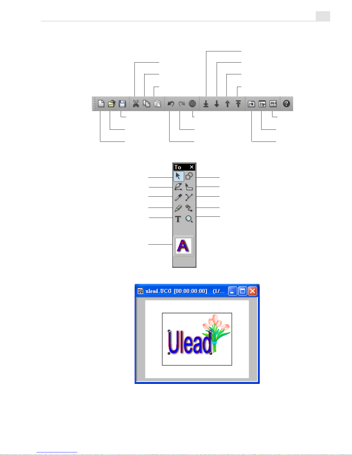
CG INFINITY: CHAPTER ONE
5
Standard toolbar
Tool panel
Edit window
Save a
CG project
Open a
CG project
Create a new
CG project
Cut an
object
Copy an
object
Paste an
object
View in wireframe
mode
Redo an undone
action
Undo a previous
action
Bring an object to
the front
Bring an object
forward
Send an object
backward
Send an object to
the back
Show the Time
Control Panel
Show the Object
Style Panel
Show the
Production Library
Object tool
Shape tool
Freehand tool
Envelope tool
Eyedropper tool
Default object style
Adjust tool
Path tool
Moving Path tool
Text tool
Zoom tool
Page 74

VIDEOGRAPHICS LAB USER GUIDE
6
Understanding objects
Objects form the basis of your work in CG Infinity. They can be anything
from text to regular squares and circles as well as freehand drawn shapes.
Each object is a vector-based graphic which is created from a series of
lines that form an outlined path to represent the object’s shape.
When you work on an object, you can add, move, and remove points
anywhere along a line in the path. These points are referred to as nodes
which, when selected, contain handles that you can drag to reshape the
path. Once you have finished creating a path, you can then specify the
object’s style attributes such as its color, whether or not it has a shadow
and how well it blends into the background.
Starting a new CG Infinity project
Every CG Infinity project begins with defining the frame size and video
properties of the project. Once created, you can begin adding text and
objects, and then manipulate them with various drawing tools. When you
are finished, you can create a video file of your work or insert the CG
Infinity project into Video Editor as part of a larger project.
To create a new CG Infinity project:
1. Click the New button on the Standard toolbar or File: New [CTRL+N] to
open the New dialog box.
2. Specify the duration of the project in the Duration spin boxes and the
frame rate in the Frame rate combo box. You can choose from the list
in the drop-down menu or enter your own.
If the project is intended to be part of a Video Editor project, make sure
that both projects have the same frame rate. If different, you may get
dropped or duplicated frames.
3. Select the frame size of the project using the options in the Frame size
group box. Again, if the project is intended to be part of a Video Editor
project, make sure that both projects have the same frame size to
prevent resampling.
Page 75

CG INFINITY: CHAPTER ONE
7
4. Click OK. The dialog box closes and a new edit window appears in the
CG Infinity workspace.
Changing the background of an edit window
Once created, an edit window displays a solid white background. When
you create a video or image file, this is the color of the background that
will appear behind any objects. You can change this background by choosing a new color or by replacing it with the contents of a video or image
file.
To change an edit window’s background:
1. Click View: Background to open the Background dialog box.
2. Select the type of background you want from the Background source
group box. You can select a general background color by right-clicking
on the color square and selecting a color from the pop-up menu that
appears. (You can also enter the RGB values for a color directly into the
RGB spin boxes.) To use an existing image or video file, click on the
appropriate option and then click the Select button. (When choosing a
video file, you can select a specific frame to insert.) You can also
choose to resize the image or video to fit the frame, or have it centered.
(If you choose to resize, the image or video may appear distorted.)
3. Click OK. The dialog box closes and the background changes accordingly. To view any changes, switch to Preview mode.
Page 76

VIDEOGRAPHICS LAB USER GUIDE
8
Changing the view of an edit window
CG Infinity offers the same controls for viewing edit windows as Video
Paint: these are the View commands and the Zoom tool. CG Infinity,
however, adds two extra commands to help you work at full screen: the
View: Full Screen
[CTRL+U] and View: Hide Menu Bar commands.
Clicking View: Full Screen displays the edit window at the current zoom
level occupying the entire screen; in its default mode, the program window
and all docked toolbars and panels are hidden, leaving only your objects
and any floating toolbars and panels in view. Full screen mode is very
useful when you want to edit an object in as much space as possible
without the distractions of the program window. Any floating toolbars or
panels remain visible in this mode, allowing you to continue working on
your object. (To return to the Normal screen mode press the [
ESC] key.)
If you prefer to have all the toolbars and panels present, click View: Hide
Menu Bar. This removes the title and menu bars of the CG Infinity screen
only, leaving all other screen elements present. (You can still use the menu
commands with their keyboard shortcut keys. To return to the Normal
screen mode press the [
ESC] key.)
Viewing objects
In CG Infinity, you can view objects in one of two modes: Preview or
Wireframe. Preview mode displays objects complete with all their object
attributes, such as fill color, shadow and transparency. While this provides
the most accurate view of an object, it can slow down editing and processing time as CG Infinity has to continually refresh these attributes whenever
you change the view of an edit window or create new objects. To speed
up editing, switch to Wireframe mode by clicking the Wireframe button
on the Standard toolbar or View: Wireframe
[CTRL+D]. This displays only
the path of each object and reduces processing time considerably as there
is less information to handle. (To return to Preview mode, deselect the
Wireframe option.)
Note: To move an object in Wireframe mode, you can only click on its path and not
the area within its shape.
Page 77

CG INFINITY: CHAPTER ONE
9
Saving your work
In CG Infinity, the edit window you are working on is referred to as a
project. You save this project as a special Ulead CG Infinity file (UCG) by
clicking the Save button on the Standard toolbar or File: Save
[CTRL+S].
UCG files contain all the attributes of the objects in the edit window as
well as the video properties of the project. Once saved, you can load the
UCG file back into the CG Infinity workspace by clicking the Open button
on the Standard toolbar or File: Open
[CTRL+O]. You can also open the file
in Video Editor by selecting the UCG format from the Files of type
combo box in the Insert Video File dialog box. The file opens as a clip in
the Timeline displaying the same object attributes as in CG Infinity. (Any
background image or video file specified in CG Infinity is not displayed.)
Creating video and image files
Once you have finished working on a CG Infinity project, you can create a
new video or image file that combines the project’s objects with the
current background. To create a video file, click File: Create Video File.
This opens the Create Video File dialog box, which has the same options as
Video Editor. To create an image file, click File: Create Image File. This
opens the Create Image File dialog box, which allows you to select the
data type, file format, resolution and size of the image.
Performing Cut and Copy operations
In CG Infinity, you can copy objects in a number of ways, such as using
the Cut and Copy buttons on the Standard toolbar or clicking Edit: Cut
and/or Copy. These allow you to duplicate objects from an edit window
and then paste them into the same or another edit window. (Copy duplicates a selected object while Cut removes it from the edit window.)
Note: You can also paste the object into an image editor such as Ulead PhotoImpact.
If pasting into PhotoImpact, the mask information is retained.
Page 78

VIDEOGRAPHICS LAB USER GUIDE
10
Another method to cut and copy is the Edit: Duplicate command which
copies the currently selected object and makes a duplicate at the same
time. The advantage of the Duplicate command is that you do not have to
paste the object, therefore allowing you to quickly create copies of objects
as you work. (This is ideal if you are creating temporary objects to
experiment on and do not want to affect the original.)
Note: You can add an object or its style to the Production Library by clicking the
appropriate command from the right mouse button pop-up menu. Once added, you
can copy it to another object by dragging-and-dropping its thumbnail onto the object.
Performing a paste operation
When pasting an object, CG Infinity gives you a variety of options for
controlling which attributes of the object to paste. For example, to paste
the object as is, click the Paste Object button on the Standard toolbar or
Edit: Paste
[CTRL+V]. This places the object in the center of the current
view. To paste only certain attributes, such as the fill color or shadow,
click Edit: Paste - Object Style. This opens the Paste Object Style dialog
box which allows you to select which attributes to paste. Once you click
OK, the attributes are pasted to all selected objects. (If no objects are
selected, this command is disabled.)
Two other paste commands, Moving Path and Object as Moving Path,
enable you to paste the moving path attributes of an object or use the path
of an object as a moving path. To apply an object’s moving path to another
object, click Edit: Paste: Moving Path. This opens the Paste Moving Path
dialog box which allows you to select between pasting the path and/or
keyframe information to the currently active object.
The Object as Moving Path command allows you to use the shape of an
object as a moving path for the currently active object. For example, you
could draw around a background image in the edit window frame and then
paste the shape of the resulting object as a moving path for another object
to follow. (For more on moving paths see ‘Creating a moving path’, page
30.)
Page 79

CG INFINITY: CHAPTER ONE
11
Controlling the alignment of objects
When you move objects around in CG Infinity, you often want to place
them in particular areas within the frame of the edit window. This is
especially the case when trying to match an object with a background video
or image file, such as a car or a corporate logo. To do this, CG Infinity
provides guides and rulers that help you accurately place and move objects.
Displaying rulers
Rulers provide you with a consistent reference point in the edit window
that identifies the location of objects. To display the rulers, click View:
Rulers. Horizontal and vertical rulers appear along the top and left side of
the edit window. They take their measurement in pixels with the base
reference point (X=0, Y=0) at the top left corner of the frame in the edit
window. You can reset this reference point by dragging the intersecting
ruler lines from the Base Point button at the corner of the rulers to any
position in the edit window. This is especially helpful if you have zoomed in
on an object and want to reset your ruler at a new view.
Note: Double-clicking the Base Point button repositions the base point to the top
left corner of the edit window frame.
Displaying grid and guides
To better position objects, it is a good idea to display the grid as well as use
guidelines within the edit window. The grid is a pattern of points that
appear whenever you click View: Grid. The grid points make it easier to
align objects and position them. You can also change the color of grid
points as well as the distance between each for greater flexibility and
control.
Page 80

VIDEOGRAPHICS LAB USER GUIDE
12
Guides are reference lines that you pull out from either the horizontal or
vertical rulers. When you pull out a guide, it appears as a dotted line which
you can use to mark certain areas within the edit window. You can have
any number of guides which can be easily repositioned by dragging on
them. To remove a guide, drag it off the edge of the edit window using the
Object tool.
Customizing the grid and guides
The default color for grid points and guides are red and blue respectively.
Depending on your background, as well as the color of your objects, you
may want to change these to make them easier to identify. To do this, click
View: Grid & Guide Options to open the Grid & Guide Options dialog
box. Here you can specify the color for both the grid points and guidelines
as well as control the horizontal and vertical spacing between each point in
the grid. If you want your objects to "snap to" grid points or guides, select
the Snap to distance option and specify the range within which a snap
should occur. For example, a range of 5 pixels pulls an object to a grid
point whenever it is placed within 5 pixels of that grid point’s position.
Notes:
• "Snap to" works on the rectangular area of an object’s bounding box and not the
path of the object itself.
• For objects to snap to grid points and guides, you need to first select the Edit:
Snap to Guides and Snap to grid commands.
Aligning objects
While the above methods allow you to accurately place objects within an
edit window, you may also want to align a group of objects so that they
appear along the same horizontal or vertical plane. To do this, CG Infinity
provides the Edit: Align command which opens the Align dialog box. Here
you can select to position objects vertically in columns or horizontally in
rows. You can also specify to have the objects appear to the left, center or
right of each other.
Page 81

CG INFINITY: CHAPTER ONE
13
Customizing CG Infinity
To better work with CG Infinity, it is important to customize the
program’s behavior with the Preferences dialog box (opened by doubleclicking the Status bar or clicking File: Preferences
[F6]). This dialog box
has three tabs: CG Infinity, Memory, and Display.
PREFERENCES DIALOG BOX: CG INFINITY TAB
1. Apply color filter allows you to control how colors are displayed in CG Infinity,
based on the NTSC or PAL color models. Select the appropriate option if you plan
on having your video played back on an NTSC or PAL device such as a television.
If you are designing for monitor display only, leave this option clear.
2. Levels of undo/redo specifies the maximum levels of undo/redo allowed by CG
Infinity (up to 99). As CG Infinity allocates more memory for each level of undo/
redo, you may find that too high a level adversely affects performance. In such
cases, restrict the level to 3-4 only. You can of course choose not to have undo/
redo to maximize performance, but any editing done is final.
3. Number of recently opened files specifies how many file names are stored in
the Recent History list found in the File menu.
1
2
3
4
5
6
Page 82

VIDEOGRAPHICS LAB USER GUIDE
14
4. Title safe area margin specifies the margin percentage for displaying any titles
in a video project. This is useful if you intend on sending your video back out to
video tape or for broadcasting as television has a different resolution than computer monitors, and edges which are viewable on screen may disappear. As a
guideline, for NTSC devices choose 12%, PAL 10%. To view the title safe area
marquee, click View: Title Safe Area.
5. Object movement defines how far an object moves when you use the arrow keys
to adjust its position.
6. Object selection method defines how objects are selected with the Object tool.
Inside selects objects that fall within the marquee of a new selection and Touch
selects objects that are touched by the marquee of a selection area. In most
cases, use Touch as it allows you to quickly select objects without having to draw
a selection over its entirety. Inside is useful if you have a lot of overlapping
objects and only want to select a specific one without affecting any others.
Page 83

15
Working with objects
The power of CG Infinity lies in its ability to create and manipulate
objects. Using a wide range of drawing tools, you can easily create
these objects by tracing over existing images, drawing your own
shapes or using the Text tool to create impressive titles and text
effects.
Chapter 2
Page 84

VIDEOGRAPHICS LAB USER GUIDE
16
Defining an object’s style
When you create an object, it takes its form from the path or shape you
draw and its appearance from a number of attributes which make up its
style. These attributes are defined in the Object Style Panel which you
can view by clicking the Object Style Panel button on the Attribute
toolbar or by right-clicking over a toolbar and selecting the Object Style
Panel command. The panel has three tabs: General, Color, and Shadow.
By experimenting with the various options available, you can quickly learn
the types of effects and results you can create using CG Infinity.
OBJECT STYLE PANEL: GENERAL TAB
1. Line Width defines the thickness of a line when applied to an object. You can
enter sub-pixel values up to 1/10
th
of a pixel. The line is centered over the path,
with half appearing on the outside, half on the inside.
2. Anti-aliasing smoothens the edges of non-rectangular objects by blending the
areas with the background. This is particularly useful for text objects. Leave this
clear if you want a sharp edge such as with square or rectangular objects.
3. Transparency controls how transparent an object appears. The first option,
Normal Transparency, provides an even transparency over the entire object
based on the value entered in the neighboring Transparency spin box. A value of 0
has no transparency and 100 full transparency. The second option, Gradient
Transparency, controls an object’s transparency based on the pattern indicated
in the neighboring gradient square. The darker the area, the less transparent the
object while the lighter the area, the more transparent the object. To change the
gradient pattern, click on the gradient square to display the Gradient Transparency
dialog box. Here you can control the start and end values of the gradient as well as
the pattern, either linear or bidirectional. (A value of 0 is white, full transparency
and 100 is black, no transparency.) To toggle between applying a linear or
bidirectional gradient, click the Gradient Style button at the bottom of the dialog
box. You can also change the direction and extent of the gradient by dragging on
the sample image.
1
2
3
4
5
6
Page 85

CG INFINITY: CHAPTER TWO
17
4. Soft Edge blends the edges of an object with the background. This option is
useful if anti-aliasing does not create a smooth enough edge for some objects.
5. Line Caps defines how the ends of lines are drawn; you can choose between
Round, Square or Flat. (Depending on the size of your object, you may not be
able to see any obvious change.)
6. Line Joints defines how lines meet; you can choose Round, Bevel, or Miter
joining. (Depending on the size of your object you may not be able to see any
obvious change.)
OBJECT STYLE PANEL: COLOR TAB
1. Fill color determines how an object is filled. The first option, None, applies no fill
to an object making it clear. The second option, Color, fills an object with a solid
color which you choose by right-clicking the color square or by selecting it from
the Color Palette, or with the Eyedropper tool. The third option, Gradient, fills an
object with a special gradient pattern. To choose the gradient, click the color
square to open the Magic Gradient dialog box and select a gradient from one of
the available methods. The final option, Texture, fills an object with a special
texture pattern. To choose this texture, click on the color square to open the
Magic Textures dialog box and select a texture from one of the displayed thumbnails.
2. Fill type specifies how to apply the fill. The first option, Even-Odd Fill, toggles
between filling the entire object or only areas which do not overlap. When not
selected, the fill is applied to the entire object, otherwise the fill is only applied to
areas where there is no overlap. (If the object does not have any overlap, then the
fill is applied to the entire object.) The second option, Fill Precedence, toggles
between applying a fill to overlapping areas or entire areas of an object. When not
selected, the entire object is filled, otherwise any areas of objects which overlap
are filled, leaving exposed areas untouched.
1
3
2
Page 86

VIDEOGRAPHICS LAB USER GUIDE
18
3. Line color determines how the line of an object is filled. The first option, None,
applies no fill to an object’s line making it clear. (If you do not select a color or
style, then the line width specified in the General tab has no affect.) The second
option, Color, selects a solid color to fill the line with. To choose the color, rightclick the color square or select the color using the Eyedropper tool or the Color
palette, keeping the [
CTRL] key held down as you click. (If you don’t hold down the
[
CTRL] key, you will be changing the Fill color instead.) The third option, Gradi-
ent, fills the line with a special gradient pattern. To choose the gradient, click the
color square to open the Palette Ramp Editor dialog box and select a pattern from
one of the available methods. Once you have selected a pattern, you can determine its direction with the neighboring three directional buttons, Along, Out-
ward, and Symmetrical. Along applies the fill evenly along the line while
Outward applies the fill from the inside out. Symmetrical applies the color from
both the inside and outside edges towards the center.
OBJECT STYLE PANEL: SHADOW TAB
1. Shadow options determine the type of shadow to apply to an object. The first
option, None, does not apply any shadow while the second option, Drop, applies a
drop shadow. You can specify the position of the shadow in the X and Y spin boxes
as well as control its transparency and the amount of soft edge in the Transpar-
ency and Soft edge spin boxes. The third option, Glow, applies a shadow to an
object so that it appears evenly on all sides. You can specify the color of the
shadow as well as its intensity in the Options group box. (The greater the intensity,
the farther out the shadow extends.) You can also set the transparency and the
amount of soft edge in the Transparency and Soft edge spin boxes. The final
option, Extrude, applies a shadow so that it comes out from an object. You can
specify the position of the shadow in the X and Y spin boxes as well as choose
between a solid or gradient color. If you choose a gradient color, you can change it
by clicking the color square to open the Palette Ramp Editor dialog box. You can
also choose to have the shadow extrude away in horizontal layers or along in
vertical layers.
Note: To change the color of a shadow, right-click on the color square or select the
color using the Eyedropper tool or the Color palette, keeping the [
SHIFT] key held
down as you click.
1
Page 87

CG INFINITY: CHAPTER TWO
19
Setting your default object style
Whenever you create an object, it takes its initial style from the current
default as indicated by the graphic at the bottom of the Tool panel. You can
change this default at any time by right-clicking it and choosing the Prop-
erties command. In the Properties dialog box that opens, you can specify
the new defaults. To use an existing object’s style as the default, first
select it and then click the Set As Default Object Style command from
the right mouse pop-up menu. The graphic in the Tool panel changes
accordingly to reflect the new style. (You can also change the default style
by dragging-and-dropping a style directly from the Style gallery in the
Production Library to the graphic on the Tool panel.) If you wish to apply
the default style to another object, first select the object and then choose
the Use Default Style command from the right mouse pop-up menu.
Creating text and shape objects
CG Infinity is designed specifically for creating various text and shape
objects. The Text tool is ideal for producing impressive opening and
ending credits as well as flashy text effects. The Shape tool creates
regular shapes such as squares and polygons while the Path and Freehand
tools enable you to draw your own objects and even trace over existing
images.
Page 88

VIDEOGRAPHICS LAB USER GUIDE
20
Using the Text tool
The Text tool in CG Infinity allows you to use any font currently installed
on your system to create a text object. Once created, you can control the
spacing between letters in a word as well as the spacing between lines of
text. You can also edit the text at a later time, even after changing its shape
and style.
Note: If you want to edit a text object on another machine, that machine must have
the same font installed. If not, the text uses your system’s default.
To create a text object:
1. Click the Text tool from the Tool panel. The Attribute toolbar changes
to display the various font characteristics you can choose from.
2. Select the font you want to use as well as any other font characteristics
such as size, bold and italics. You can also specify the alignment of the
text as well as the kerning and leading.
Note: Kerning decreases the amount of space between letters in a word making
it appear tighter while leading affects the spacing between words on different
lines. The default 100% uses the font’s own leading with lower values decreasing the space and higher values increasing the space.
3. Click the edit window where you want the text to appear and start
typing in your text. (To add a line, press the [ENTER] key.)
If you are including a lot of text, such as credits, drag your mouse to
create a text bounding box. When you type your text, it wraps to the
edges of this bounding box.
4. Change to the Object tool or click outside the text area to place the
text as an object.
Creating a text object
Page 89

CG INFINITY: CHAPTER TWO
21
Using the Shape tool
In CG Infinity, you can create both regular symmetrical shapes, such as
squares and circles, as well as more complex polygons and stars. You can
use these shapes to block out sections of a background image or video, as
a background for text, or to create a variety of special effects.
To create a shape object:
1. Select the Shape tool from the Tool panel. The Attribute toolbar
changes to indicate the various shapes you can choose from as well as
how the shape is created.
2. Select the shape you want to use from the Attribute toolbar and then
select the drawing options for creating that shape.
There are three options you can choose from to control the way a
shape is drawn. The first, From Center, creates the shape from the
center moving out. If not selected, the shape is created from the top
left corner down as you draw. The second option, Equal Sides ensures
that the sides of the shape are all of equal length. If not selected, you
can draw a shape with variable width and height. The final option,
Fixed Size, allows you to specify the exact width and height of an
object in the neighboring Width and Height spin boxes. (Selecting this
option disables the Equal Sides option.)
Another option, Sides, is only available for the Polygon and Star
shapes and controls the number of sides present in these shapes. Star
also has an additional option, Pointiness, which controls the length of
each star cone in relation to the core of the star. For example, a value
of 0 would produce no star cones, only the star core. A value of 50%
would produce half star cones and half star core while 100% would
produce only star cones with no star core.
Note: You can change the pointiness of a star object by holding down the
CTRL+ALT keys as you drag. Dragging inward increases the pointiness while
dragging outward decreases it. (The size of the star remains unchanged.)
Page 90

VIDEOGRAPHICS LAB USER GUIDE
22
3. Click on the area of the image where you want the shape to appear and
drag. As you drag, the shape takes its form based on the specified
attributes. (If you choose a fixed size, the shape is drawn immediately.)
Once you release your mouse, the shape is created as an object.
Note: If you draw an object and then hold down the [SHIFT] key, you can adjust the
object equilaterally. If you hold down the [
CTRL] key, you can adjust the object in
one direction only.
Creating a variety of shapes
with the Shape tool
Using the Freehand tool
The Freehand tool allows you to create any kind of shape you want by
allowing you to draw it with your mouse. This is particularly useful for
tracing over elements in a background video or image file, such as a
person’s head or a corporate logo. Once you have finished drawing your
path, CG Infinity then places nodes in positions on the path, where necessary, to maintain the accuracy of the shape you have drawn.
To create a freehand object:
1. Select the Freehand tool from the Tool panel. The Attribute toolbar
changes to display the options for drawing a path.
2. Move to the edit window and begin drawing the shape you want to
create or trace.
Page 91

CG INFINITY: CHAPTER TWO
23
As you draw, a line appears in the edit window which follows your
movements. To draw continuously, keep your mouse button down as
you drag. If you release the mouse button, you end a segment. You can
then choose to end the path or create a new segment by clicking in
another area of the edit window. When you create a new segment, it
automatically connects to the end of the previous segment.
Note: If you make a mistake while drawing, press the [ESC] key to start again.
3. Click the Close or Open Path button on the Attribute toolbar to end
your shape. (Close Path draws a line connecting the ending and
starting points of your path, while Open Path leaves it as is.) A red
line appears following the path you have drawn. CG Infinity uses this
line to determine how many nodes to place on the resulting path. To
have the line more closely follow your own, increase the value in the
Accuracy spin box on the Attribute toolbar.
4. When you are satisfied with the accuracy of your path, switch to the
Object tool or click outside the area to place the shape as an object. (If
you chose an Open Path, you need to specify a line width and fill color
in the Object Style Options panel to see the path clearly.)
Using the Path tool
The Path tool is similar to the Freehand tool with the exception that it
allows you to create shapes based on a series of straight or curved lines.
You can manipulate these lines as you draw them or come back to them at
a later time for further adjustments.
To create a path object:
1. Select the Path tool from the Tool panel. The Attribute toolbar changes
to display the options for drawing a path.
2. Select the type of path you want to draw from the Attribute toolbar.
You can choose between drawing in straight lines or curved line
segments by clicking the appropriate button on the Attribute toolbar.
(You can switch between linear or curved segments as you draw
depending on the type of path you are trying to create.)
Page 92

VIDEOGRAPHICS LAB USER GUIDE
24
3. Move to the edit window and begin drawing the shape you want to
create. Each time you click your mouse, a node is placed in the edit
window and a line segment is automatically drawn connecting the two
nodes. If you selected the Add Curve option, two handles appear on
either side of the node allowing you to stretch, pull and turn the curve.
(You can come back later to edit these nodes and handles using the
Adjust tool, see page 28.)
Note: If drawing in straight line segments, you can hold down the SHIFT key to
restrict the line to movements of 15º intervals.
4. Click the Close Path button on the Attribute toolbar to end your shape.
CG Infinity automatically draws a line connecting the end of the last
segment to the beginning of the shape, filling it with the currently
specified fill color. If you want to leave the shape open, such as for
creating lines, click the Open Path button on the Attribute toolbar. This
fills the line of the shape only, leaving the contents clear. (To view an
open path, you need to specify a line width in the Object Style Options
panel.)
Selecting and transforming objects
Once you have created an object, you can move and manipulate it in a
variety of ways. The easiest is with the Object tool which allows you to
select objects and then move and resize them anywhere within the edit
window. In CG Infinity, you can select a single object or multiple objects,
group them, or place them on top of, or behind, others. To select an
object, click the Object tool on the Tool panel and then click the object
you want to select. (You need to click a portion of the shape, such as the
line or filled area. This may not be so easy for open shapes with small line
widths. In such instances, increase your magnification or the line width.)
Notes: You can also select an object by dragging a selection marquee over it.
Depending on your settings in the Preferences dialog box (see page 13), you have
to drag over the entire object or simply touch one of its edges.
Page 93

CG INFINITY: CHAPTER TWO
25
Selecting multiple objects
You can select multiple objects by holding down the [SHIFT] key as you
click each object. The bounding box changes each time to encase all the
selected objects. Once selected, you can move them as one or resize them
equally. If you change an object style, the new style is adopted by all the
objects, regardless of their original settings. (You can also select multiple
objects by dragging a selection marquee over each one.) To remove an
object after selecting it, hold down the [
SHIFT] key and click again. (You
can only deselect objects in the reverse order that they were selected.)
Grouping objects
If you selected multiple objects, you can group them together so they act
as one. Once grouped, you can move the objects together as well as
duplicate them to make additional copies. Grouping objects is especially
useful at the end of a project when you have layered them in their final
positions. To group objects, select them and then click Edit: Group. To
ungroup them, select the grouped object and then click Edit: Ungroup.
Layering objects
An important part of working with objects is being able to layer them on
top of and behind one another to create a variety of effects such as
shading and transparency. To control the layering of objects, CG Infinity
provides several commands in the Edit menu as well as options on the
Standard toolbar. For example, you can send an object behind another by
clicking the Send Backward command or, if there are several objects,
send the object to the bottom of the others by clicking the Send to Back
command. To place objects in front of others, click either the Bring
Forward or Bring to Front commands.
Notes:
• To move an object quickly through the layers, use the direction arrows on the
Standard toolbar.
• All new objects are placed above existing objects.
Page 94
VIDEOGRAPHICS LAB USER GUIDE
26
Moving objects
Once an object is selected, you can move it by dragging it with the Object
tool. Apart from moving an object with your mouse, you can also move it
using the Position spin boxes on the Attribute toolbar. When you view the
Position spin boxes, they show the current horizontal and vertical position
of the selected object respectively (All measurements are in pixels). You
can enter in new values to move the object accordingly. This is very useful
if you are working with various layers of objects and you want to move
one by a fraction of a pixel, such as when creating shading effects.
Transforming objects
In CG Infinity, you can transform an object using the Object and Envelope
tools. When you transform an object, you can adjust its shape and rotation
as well as resize it so that it fits better inside the edit window frame.
Transforming works by dragging the handles on the bounding box of a
selected object. Depending on the type of transform you are performing,
these handles appear either on the sides and corners of the bounding box or
just the corners. (To manipulate the actual path of an object you need to
use the Adjust tool, see page 28.)
Using the Object tool
The Object tool provides five options on the Attribute toolbar for resizing
and rotating an object. The first option, Resize, allows you to drag on the
nodes of a bounding box to stretch and pull an object. (If you want the
object to change its size proportionally, hold down the [
SHIFT] key as you
drag.) To rotate an object, select the Rotate option. As you rotate, the
degree of the rotation is displayed in the Rotation Angle spin box at the
end of the Attribute toolbar. For finer adjustments, you can use this spin
box or enter in the degree of rotation directly. You can also reposition the
rotation circle, found in the middle of the object, to determine where the
center of rotation is, such as the top left corner or right side. (To return
the rotation circle to the middle, click the Reset Rotation Center button
next to the Rotation Angle spin boxes.)
Page 95

CG INFINITY: CHAPTER TWO
27
Note: To resize an object, you can click a button or enter the new dimensions for
the object in the Width and Height spin boxes on the Attribute toolbar. (These spin
boxes are useful when you need to make accurate adjustments to an object’s size
such as to 1/10th of a pixel.)
Using the Envelope tool
The Envelope tool differs from the Object tool in that it works by providing a shape which you fit an object into, rather than having an object define
its own shape. This is particularly useful for text objects whose shapes
take their form from a particular font. By changing the envelope of the
text, you have much greater flexibility over how the text is warped and
distorted. For example, you could make the text appear as a wave or have
it bend in three dimensions.
To change the envelope of an object:
1. Create a text object and then select the Envelope tool from the Tool
panel. A bounding box appears around the text with nodes on the sides
and corners.
2. Select a method to control the envelope from the Envelope method
combo box on the Attribute toolbar. You can choose between four
types: Fit Shape, Fit Length, Horizontal and Vertical. (The result of
each of these methods may differ depending on the size and font of
your text.)
Original image Resizing Rotating
Slanting Perspective Distorting
Page 96

VIDEOGRAPHICS LAB USER GUIDE
28
3. Drag one of the nodes of the bounding box to change the shape of the
envelope. Control handles appear which allow you to further control the
curve of the envelope.
4. Keep dragging the nodes and control handles until you have a shape you
are happy with.
Adjusting shapes
Whenever you create an object (other than a text object), its shape is
defined by the path you draw. Once created, you can come back to this
path and change it using the Adjust tool. The Adjust tool is particularly
useful if you have traced an object or created your own freehand drawing
and need to modify it so that it better takes the shape you want.
To adjust a path:
1. Select the Adjust tool from the Tool panel. The Attribute toolbar
changes to display the options for adjusting a path. Nodes also appear
on the path of the selected object. (You cannot adjust the path of a text
object.)
2. Select the Adjust Path button (if it is not already selected) and click
any node on the path of the object. The node changes to black to
indicate it is active and control handles appear on either side of the
node.
Changing the envelope of a text object
Page 97

CG INFINITY: CHAPTER TWO
29
3. Change the shape of the path by dragging the node or one of the
control handles. Dragging the node repositions it while dragging a
control handle changes the curvature of the path around the active
node and between the preceding and following nodes. You can control
the behavior of these nodes as well as their directions by choosing one
of the node options on the Attribute toolbar. In all, there are five options
you to choose from:
Curve Segment changes the curvature of a path between the preceding, following and active nodes.
Line Segment changes the shape of the path to straight line segments
beginning from the preceding node to the active node.
Symmetric Node changes the curvature of the path between the
preceding, following and active nodes, keeping the control handles
fixed in a linear path and equal in length. (This button is active only if
the Curved Node option is selected). This option is best for performing
general changes to a path’s curvature.
Smooth Node changes the curvature of the path between the preceding, following and active nodes, allowing you to change the length of
the control handles independently from each other (they still remain on
a linear path). Use this option for greater control over the curvature
with respect to the preceding and following nodes.
Cusp Node changes the curvature of the path between the preceding,
following and active nodes, allowing you to move one control handle at
a time. This is useful when you want to change the curve on one side
of the path without affecting the other.
4. Keep dragging nodes and control handles until you have a shape you are
happy with.
Notes:
• To add a node, click anywhere along the path of the object with the Add Node
button selected from the Attribute toolbar. To remove a node, click the node
with the Remove Node button selected.
• You can make a path closed or opened by clicking the respective buttons on
the Attribute toolbar.
Page 98

VIDEOGRAPHICS LAB USER GUIDE
30
Creating a moving path
An integral part of your work in CG Infinity is adding motion to your
objects. This is done using the Moving Path tool which allows you to
specify a path for an object to follow within the edit window. You can then
position objects so that they move across the screen, either in unison or at
different intervals. You can even perform various special effects such as
fades from one color to another as well as changing the size and rotation of
an object as it travels over time. Being a path, you can also adjust it just as
you would the path of any object in CG Infinity, providing for extremely
fine and accurate movements.
Notes:
• Any moving path you create takes its time from the duration specified in the
Properties dialog box, opened by clicking File: Properties.
• To delete a moving path, select the object with the Moving Path tool and then
click Edit: Delete [
DELETE]. (If there is no moving path, the object is deleted.)
To create a moving path:
1. Position the object where you want it to start its movement and then
select the Moving Path tool from the Tool panel. The Attribute toolbar
changes to display the various options available and Start and End
nodes appear on the selected object.
Note: Selecting the Moving Path tool should open the Time Control Panel. If it
does not, click the Time Control Panel button on the Standard toolbar to
display it. (If the Moving Path tool is not the current tool, it is automatically
hidden.)
2. Click the End node and drag it to where you want the moving path to
end.
3. Click the Play button on the Time Control Panel to see how the
object moves. (It is best to do this in Wireframe mode as it speeds up
the playback considerably.) To adjust the path’s position or shape, drag
on the Start and End nodes.
Notes:
• Depending on the type of path, you may have to click twice before being able
to move a Start or End node.
• To view a moving path at anytime, click on it with the Moving Path tool.
Page 99

CG INFINITY: CHAPTER TWO
31
Creating a moving path
Changing the shape of a moving path
In CG Infinity, there are two ways in which you can change the shape of a
moving path: with the Moving Path tool or by assigning the path of an
object as a moving path. To change the shape using the Moving Path tool,
you need to select it with the Moving Path tool and then drag the moving
path as you would if adjusting an object’s path. The Attribute toolbar has
the same options as the Adjust tool (see page 28). To create greater movement, you can add nodes anywhere along the path and edit them as you
would with the Adjust tool.
To assign the path of an object as a moving path, first select the object and
then copy it. Now select the object you want to move and click Edit: Paste
Object as Moving Path. The path of the copied object now appears in the
center of the selected object as a moving path. This is useful if you want an
object to follow the shape of a particular feature, such as stars following
the outline of a corporate logo.
Changing the shape of a moving path (left)
and pasting an object as a moving path (right)
Page 100

VIDEOGRAPHICS LAB USER GUIDE
32
Changing the size and style of an object over time
Using the Time Control Panel, you can make an object change its size
over time as well as perform other effects such as fades and color transitions. This is done through the use of key frames that you place at strategic positions throughout the moving path. By changing the attributes of an
object at each key frame, you cause it to change over time.
To change an objects size and style over time:
1. Select the object you want to change with the Moving Path tool. The
moving path of the object appears.
2. Move the Preview slider in the Key frame Controller to the frame in
the path where you want the object to change. The object moves to
that frame position on the moving path.
3. Click the Add Key frame button on the Time Control Panel. A key
frame is added to the Key frame slider.
4. Change the style and size of the object using the Object Style Panel as
well as the resize buttons on the Attribute toolbar. If you are changing
the style, any changes to the fill color options produces a fade effect
from one to the other, as long as two fill colors are of the same type,
for example, going from a gradient fill to another gradient fill. If the
types are different, no fade occurs and the style changes only at the
second key frame position.
You can also control the transparency of the object as it moves over
time by adjusting the control points in the Fade graph. Moving a control
point upward makes the object more transparent: downward less
transparent.
5. Repeat steps 3 and 4 to add more key frames. (To edit an object at an
existing key frame position, you must first make it active by clicking on
its key frame in the Key frame slider.)
6. Move the Preview slider to the start or click on the Start Key frame
button to return the object back to its beginning position.
7. Click the Play button to see how the object moves and changes over
time. (To see changes in an object’s style, you need to play the moving
path in Preview mode, not Wireframe.)
 Loading...