

Page 1

UHER
SG561
Betriebsanleitung
Operating Instructions
ROYAL
Instructions d'emploi
Page 2
Sikr-
UHER-Ingenieure
eine Vielzahl von Möglichkeiten gesteckt, die zu verstehen und
zu nützen eine genaue Lektüre dieser Bedienungsanleitung erfordert.
Es wäre schade, wenn Sie durch Unkenntnis nicht zu dem vollen
Gegenwert Ihres Geldes kämen.
our engineers
apparatus you have
utilizing
Instructions.
you would not enjoy
Avec
le
d'une multitude de possibilites
par
les
un
apercu
les mettre pleinement ä
de cette brochure.
q.nüdu}je.
Cf
Cf-Himd.
utwufm
haben in das von Ihnen erworbene Gerät
have
built
a great number of
them,
magnetophone que vous venez
Ingenieurs
complet de ces possibilites, et vous ne pourrez
purchased,
demands a careful perusal of these Operating
It
would
be a pity if
füll
de
la
understanding these facilities and
through
value
for your money.
interessantes,
Maison
UHER. Vous
prosit
qu'apres
facilities
lack of knowledge,
d'acquerir,
mises
n'obtiendrez
la lecture attentive
into the
vous disposez
au point
Achtung
Das Typenschild mit der Gerätenummer befindet sich unter der Andruckrolle, die nach Abziehen der vorderen Tonkopfabdeckung sichtbar wird.
Die Angaben über Betriebsspannung, Netzfrequenz und Leistungsaufnahme befinden sich im Kabelfach (B) (s. Abb.
Note
The type designation shield bearing the number of the machine is located
beneath
the pressure roiler; it
cover
has
and power
Fig. 1) on the bottom side of the machine.
Attention!
L'etlquette
se trouve sous le
de la
cisant la tension de fonctionnement, la
et le wattage sont inscrites dans le
been removed. Data on operating current,
consumption
signaletique
coiffe
galet
de protection avant des
may
be seen once the front
are found in the
qui
porte
le
presseur (ce dernier est visible apres le
numero
tetes
compartiment
1)
cable
de
magnötiques).
frequence
an der Geräteunterseite.
tape-head
mains
compartment (B) (see
serie
de la tension du secteur
(B) du
frequency
du magnetophone
demontage
Les valeurs
cäble
(voirfig.
pre-
1).
Page 3
Inhaltsverzeichnis
1.
Beachten Sie bitte folgendes, wenn Sie Ihr Gerät
aufstellen
Luftzufuhr für Wärmeaustausch
Betriebslage
Länge der Verbindungskabel
Netzanschluß-Betriebsspannung-Netzsicherung
Montage des Tragegriffes
Aufsetzen bzw. Entfernen des Klarsichtdeckels
Einlegen des Tonbandes
Anschlußbuchsen
Buchse „Mikrofon"
Buchse „Kopfhörer"
Buchse
„Phono
Buchse
„Radio/Phono
Buchse A
Buchse
~!
Buchse „Lautsprecher ^ l"
Buchse „Lautsprecher
Bedienungselemente und ihre Funktionen
Taste
„MICRO"©
Aussteuerungsregler „MICRO/RADIO"
linken (2) und rechten @ Kanal
Aussteuerungsregler „PHONO"
und rechten © Kanal
Aussteuerungsinstrument © für linken Kanal
Aussteuerungsinstrument @ für rechten Kanal
Taste MITHÖREN-VORBAND/HINTERBAND ®
Regler MULTIPLAY/ECHO ©
Doppelreglerfür
einstellung @
3.9 Regler für Lautstärkeeinstellung des linken ® und
rechten @ Kanals
3.10 Taste AUFNAHME ®
3.11
Betriebsartenschalter ©
3.12
Bandgeschwindigkeitswähler©
ö
»»
II"
^
l"
&
c3-e
+3
II"
(PHONO
Höheneinstellung ® und Tiefen-
(PHONO
II)
für linken ©
l)
für
3.13 Funktionswähler ® für STOP-PAUSE und START 8
3.14 Umspulschalter ® für Vorlauf und Rücklauf 8
3.15
Zählwerk mit Nullstelltaste ® 8
4. Anschluß des Gerätes an den Verstärker Ihrer
2
2
2
2
3
3
3
4
4
4
4
5
5
5
5
5
6
6
6
6
6
HiFi-Anlage
4.1
Anschluß von Geräten an Verstärker mit Normbuchsen
nach
4.2
Anschluß von Geräten an Verstärker ohne Normbuchsen
9
DIN
9
nach DIN 9
4.3
Anschluß des Gerätes an Verstärker mit Monitor-Eingang
4.4
Anschluß des Gerätes an Receiver, Musikschränke
oder Rundfunkgeräte 10
5.
Aufnahmebetrieb
5.1
Aufnahmebetrieb für Eilige
52
Aufnahmebetrieb für Interessierte
6.
Wiedergabebetrieb
6.1
Wiedergabegebtrieb für Eilige
6.2
Wiedergabebetrieb für Interessierte
7.
Trick- und Effektaufnahmen
7.1
Echo bei Monoaufnahmen 14
7.2
Echo bei Stereoaufnahmen 14
7.3
Synchroplay
7.4
Multiplay 15
8.
Diapilot
17
Anschluß von Zusatzgeräten und Anpassen des
g.
Gerät»;
jn
10.
Verwendung des Tonbandgerätes als HiFi-Stereo-
11
11
12
13
13
13
14
15
die jeweilige Betriebsbedingung
18
Mischverstärker 19
11.
Wartung und Pflege 20
Hinweise für den Fachhändler und technisch
12.
Interessierte 21
Kontaktbelegung, Ein-, Ausgangswiderstände und
12.1
Ein-, Ausgangsspannungen 21
12.2 Technische Daten 22
10
Page 4
1.
Beachten Sie bitte folgendes, wenn Sie Ihr Gerät aufstellen
1.1
Luftzufuhr
Das Gerät muß so aufgestellt werden, daß alle Belüftungsschlitze im
Boden des Gerätes freiliegen, damit ein einwandfreier Wärmeaustausch
erfolgen kann. Beim Einbau des Gerätes in eine Truhe oder in das Fach
einer Schrankwand muß für ausreichende Luftzufuhr gesorgt werden.
1.2
Betriebslage (s. Abb.
Das Gerät arbeitet sowohl in senkrechter als auch in waagerechter Lage.
Für Wandaufhängung sind an der Unterseite (bzw. Rückseite) des Gerätes zwei Einhängeösen (A) vorhanden.
1.3 Länge der Verbindungskabel
Anschlußkabel, die nicht durch steckbare, im Lieferprogramm vorge-
sehene, Verbindungskabel (siehe Aufstellung am Ende der Bedienungsanleitung) erweitert werden können, sollten nur von einem Fachmann
verlängert werden.
für Wärmeaustausch
1)
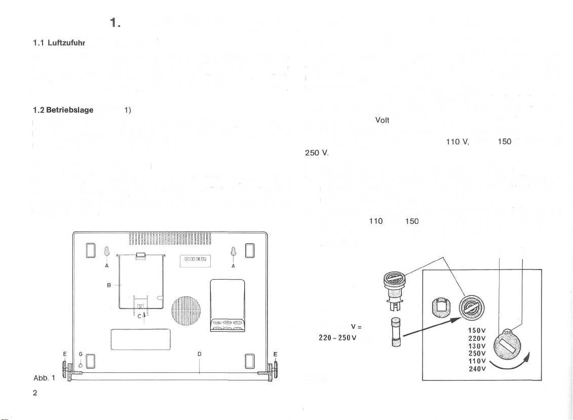
1.4 Netzanschluß-Betriebsspannung-Netzsicherung (s. Abb. 1 und 2)
Das Netzkabel befindet sich im Fach (B) am Geräteboden bzw. an der
Geräterückseite und ist nach Öffnen des Deckels zugänglich. Die selbstrastende Taste (C) des Deckels wird zum Öffnen in Pfeilrichtung gedrückt.
Dann kann der Deckel ausgeschwenkt werden.
Vor Anschluß des Gerätes ist, vor allem beim Betrieb im Ausland, die
vorhandene Netzspannung festzustellen. Das Gerät ist auf eine Betriebs-
spannung von 220
50 Hz eingestellt und kann nach einer Umschaltung auch mit folgenden
Wechselspannungen betrieben werden:
250V.
Die Umschaltung wird wie folgt vorgenommen (s. Abb. 2):
1. Es darf keine Verbindung zur Netzsteckdose bestehen. Sicherungshalter (A), der sich wie der Spannungswähler (B) im Netzkabelfach
befindet, mittels einer Münze herausschrauben.
2. Bei Betriebsspannungen von 220 V bis 250 V ist eine Sicherung von
0,6 Amp., bei
halter einzusetzen. AnschJießend Sicherungshalter wieder einschrauben.
Volt
Wechselspannung bei einer Netzfrequenz von
110V,
130 V,
150
110
V bis
150
V eine von 1,2 Amp. in den Sicherungs-
V, 240 V und
A B C
110-150
220-250 V = 0,6 At
Abb.
2
V=
1,2 At
Page 5
3. Spannungswähler (B) durch Drehen mittels einer Münze auf die vorhandene Netzspannung einstellen. Der eingestellte Wert der Betriebsspannung erscheint in der Aussparung (C). Das Netzkabel darf erst
jetzt in die Steckdose gesteckt werden.
Die Umschaltung von 50 Hz auf 60 Hz Netzfrequenz ist von einem Fachmann unter Verwendung der 60 Hz Motorrolle (Bestellnummer
und des 60 Hz Motorkondensators (Bestellnummer
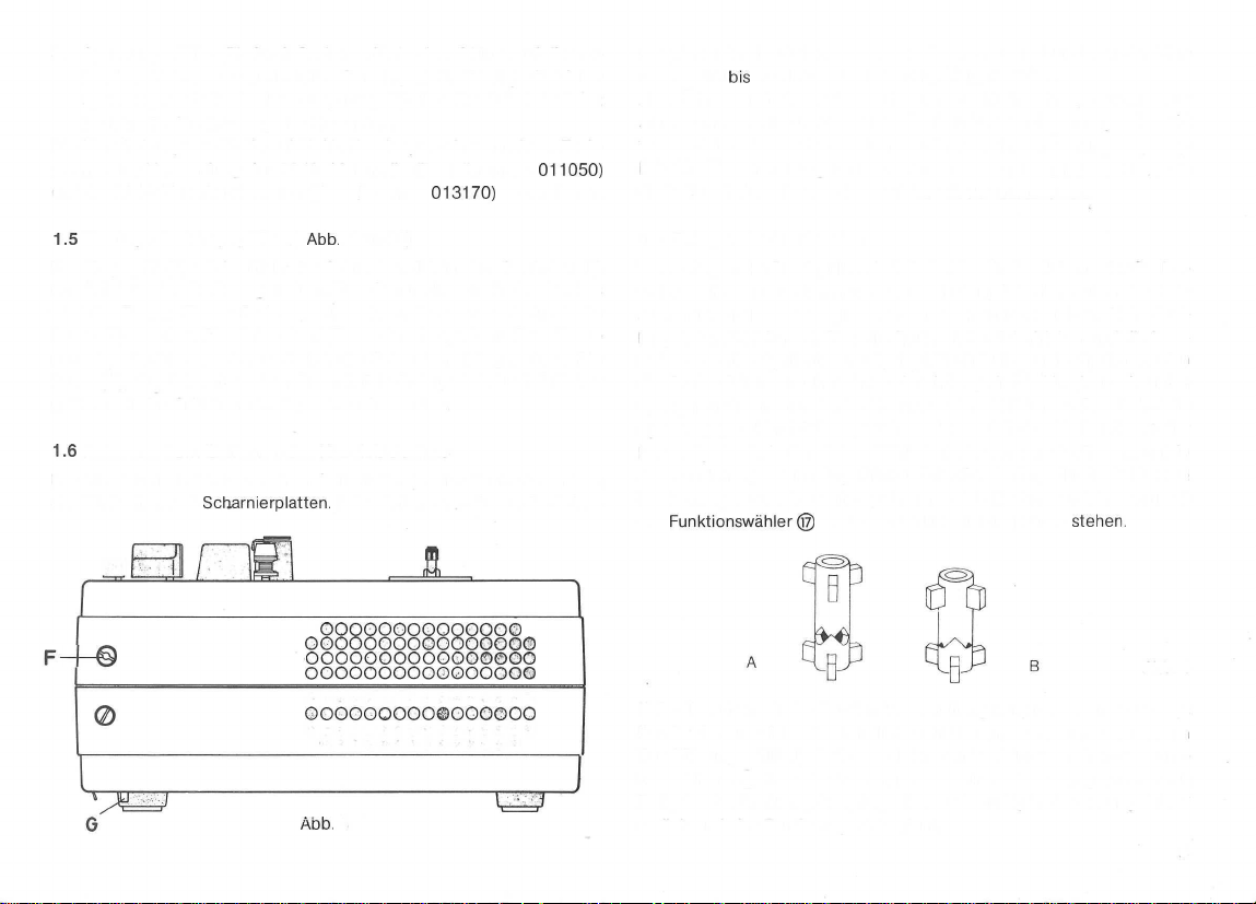
1.5
Montage des Tragegriffes (s.
Der Tragegriff (D) wird mittels der Schrauben (E) in den Gewinden (F)
am Gehäuse des Gerätes gehalten. Zum Senkrechtbetrieb des Gerätes
wird der Tragegriff zum Boden geschwenkt und automatisch durch die
Raste (G) arretiert. Die Schrauben (E) werden festgedreht. Zum Transport des Gerätes werden zunächst die Schrauben (E) gelockert. Die
Raste (G), die sich neben dem Gummifuß befindet, wird durch Drücken
gelöst und der Griff kann hochgeschwenkt werden.
1.6
Aufsetzen bzw. Entfernen des Klarsichtdeckels
Der Klarsichtdeckel hat an seinen Seitenteilen je eine Rasttaste und an
der Rückseite zwei
Scharnierplatten.
Abb.
1 und 3)
Beim Aufsetzen müssen die Schar-
013170)
011050)
vorzunehmen.
n
oooooooooooooo
oooooooooooooooo
F--©
oooooooooooooooo
OOOOOOOOOO0OOOOO
ooooooooooooooo©
ooooooooo©oooooo
oooooooooooooooo
oooooooooooooo
Abb.
3
nierplatten in die Scharniere am Gerät eingreifen, dann kann der Klarsichtdeckel
Zum Öffnen sind die beiden Rasttasten zu drücken. Im gedrückten Zustand kann der Klarsichtdeckel nach oben bzw. nach vorne geschwenkt
werden. Ein Abheben ist bereits nach einem geringen Öffnungsweg möglich. Um Verschmutzungen des Gerätes zu vermeiden, ist der Klarsichtdecker nach Ausschalten des Gerätes wieder aufzusetzen.
1.7 Einlegen des Tonbandes
Vor Auflegen der Bandspulen sind die beiden Dreizackdorne der Spulenteller nach oben zu ziehen und so zu drehen, daß die Zacken des feststehenden und des beweglichen Teiles übereinander stehen. Siehe Stellung A der Abbildung 4. Die volle Spule wird auf den linken und die leere
auf den rechten Spulenteller aufgelegt. Nach Auflegen der Spulen werden
die Dreizackdorne nach rechts oder links gedreht, bis sie nach unten
springen und einrasten. Siehe Stellung B der Abbildung 4. Damit sind die
Spulen gegen Herabfallen gesichert. Jetzt wird das Tonband von der
linken Spule über den linken Fühlhebel abgezogen, straff gespannt in
den Bandeinlegeschlitz eingeführt und der Bandanfang durch ein bis zwei
Umdrehungen auf die rechte Spule aufgewickelt. Zum Bandeinlegen muß
der
Falls die automatische Bandendeabschaltung kurz nach dem Start des
Bandlaufes anspricht, da sich die Schaltfolie am Vorspannband noch im
Bandführungsschlitz befindet, wird der Bandlauf durch Drehen des Funktionswählers @ über die Stellung START hinaus in Gang gesetzt- Nach
Freigabe des Drehknopfes springt dieser selbsttätig in die Stellung START
zurück und der Bandtransport beginnt.
bis
zum Einrasten heruntergeklappt werden.
Funktionswähler©
in jedem Fall in Stellung STOP
stehen
Abb.
4
3
Page 6
2. Anschlußbuchsen
2.1 Buchse Mikrofon
An dieser Buchse können alle niederohmigen, dynamischen Stereo-Mikro-
fone direkt angeschlossen werden, die mit
stattet sind. Bei Stereoaufnahmen mit zwei dynamischen
erfolgt der Anschluß über das Adapterkabel Typ K 626.
können über das Kabel Typ K 110 verlängert werden. Die Verlängerung
von Stereo-Mikrofonen erfolgt über das Adapterkabel Typ K
Für
Monoaufnahmen
direkt angeschlossen werden. Für den Anschluß zweier Mikrofone zur
stereofonen Aufzeichnung wird der Adapter Typ K 626 benötigt. Das gelbe
Kabelende kennzeichnet den linken, das rote den rechten Kanal. Die Verlängerung der Anschlußleitung wird über das Kabel Typ K
Adapter Typ K 626 vorgenommen. Die Stromversorgung erfolgt in jedem
Fall aus einer im Mikrofon eingebauten Batterie.
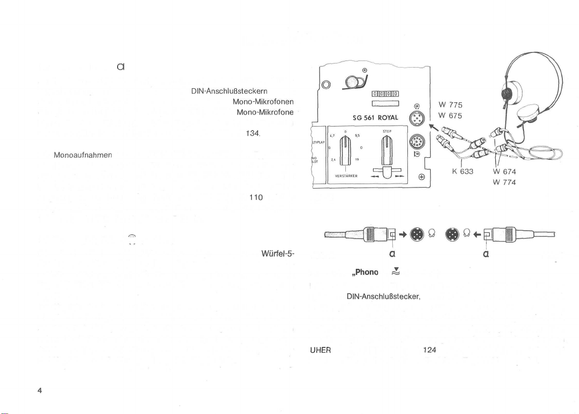
2.2 Buchse „Kopfhörer" (s. Abb. 5)
Diese Buchse dient zum Anschluß von Stereo-Kopfhörern, die mit
Steckern ausgerüstet sind, wie z.B. die Typen W 675 und W 775. Der Anschluß von Hörern, die mit LS-7-Steckern ausgerüstet sind, wie z.B. die
Typen W 674 und W 774, erfolgt unter Zwischenschaltung des Adapters
Typ K
633.
Die Kopfhörerbuchse ist mit Schaltkontakten ausgestattet, über die die
eingebauten Lautsprecher abgeschaltet werden können. Dazu ist der
Stecker mit der Aussparung a in der Steckerwandung zum Geräteäußeren
zeigend in die Buchse einzuführen (Abb. A). Zeigt die Aussparung a in der
Steckerwandung zum Geräteinneren, so läuft die Tonwiedergabe über
den Kopfhörer und die Lautsprecher gleichzeitig (Abb. B).
Q
DIN-Anschlußsteckern
Mono-Mikrofonen
Mono-Mikrofone
kann das UHER-Kondensator-Mikrofon Typ M 646
134.
110
ausge-
und den
Würfel-5-
Abb.
5
Abb.
A
2.3 Buchse
Diese Buchse dient als Eingang zum direkten Anschluß für Stereo-Plattenspieler mit
Plattenspieler mit Magnetsystemen können dann angeschlossen werden,
wenn sie mit eingebauten Entzerrer-Vorverstärkern ausgestattet sind.
Außerdem ist diese Buchse zum Anschluß von hochpegeligen Tonquellen,
wie Stereo-Tonband- oder Cassettengeräten, Stereo-Receiver oder dem
UHER
bei diesen Tonquellen die Stereo-Tonleitung Typ K 541 verwendet.
„Phono
II" ^ (s. Abb. 6)
DIN-Anschlußstecker,
Mischpult MIX 500 Typ A
die mit Kristallsystemen ausgerüstet sind.
124
geeignet. Als Verbindungskabel wird
Abb.
B
Page 7
2.4 Buchse
Diese Buchse dient zum Anschluß von Stereo-Rundfunkgeräten, Tonbandoder Cassettengeräten und Plattenspielern mit Kristallsystemen bzw.
Plattenspielern mit Magnetsystemen und eingebauten Entzerrer-Vorverstärkern, die mit Normanschlußsteckern bzw. Normanschlußbuchsen nach
DIN
Wiedergabe die Stereo-Tonleitung Typ K 541 als Verbindungskabel verwendet, über die ein Anschluß zur Buchse TONBAND der Tonquelle hergestellt wird.
Bei Verwendung von älteren Mono-Geräten ist zunächst das Adapterstück
Typ K 837 in die Anschlußbuchse des Mona-Gerätes zu stecken, bevor
eine Verbindung zum Tonbandgerät über die Stereo-Tonleitung hergestellt
wird.
2.5 Buchse A (s. Abb. 6)
Diese Buchse dient zum Anschluß des Handfernschalters Typ F
des Fußschalters Typ F
mat
Gerätes dann einschaltet, wenn ein Schallereignis auftritt bzw. den Band-
transport stoppt, wenn das Schallereignis beendet ist.
2.6
Diese Buchse dient als Monitor-Ausgang zur Herstellung einer Verbindung
zu Verstärkern, die mit einem Monitor-Eingang ausgestattet sind. Bei Verstärkern mit
Normbuchsen das Kabel Typ K 563 als Verbindungskabel (siehe hierzu
auch Abs.
Außerdem wird an dieser Buchse das Projektorkabel Typ K
schlossen, über das die Verbindung zum „Automatischen Diaprojektor"
hergestellt wird (Steuerung der Diawechselvorgänge mittels Diapilot vom
Tonbandgerät aus. Siehe hierzu auch Abs. 8).
„Radio/Phono
ausgestattet sind. Bei Rundfunkaufnahmen wird bei Aufnahme und
ist ein akustischer
Buchse
««^(s.
Cinchbuchsen
4.3),
l" Ä (s. Abb. 6)
211
oder des Akustomaten Typ F
Start-Stop-Schalter,
Abb.
6)
dient das Kabel Typ K 562, bei Verstärkern mit
der den Bandtransport des
411.
Der Akusto-
91 1 ange-
1 1 1 bzw.
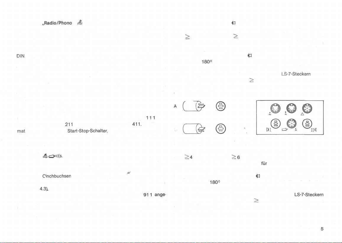
2.7 Buchse „Lautsprecher
Diese Buchse dient zum Anschluß einer Lautsprecherbox (Impedanz ^ 4 Ohm/Belastbarkeit
gegeben wird. Der eingebaute Lautsprecher für die Wiedergabe des linken
Kanals wird abgeschaltet, wenn der Stecker der externen Lautsprecherbox
gemäß Abbildung A in die Buchse
Steckers um
sprecher und die externe Lautsprecherbox den linken Kanal einer Stereoaufzeichnung hören. Es können auch Kopfhörer mit
schlossen werden, deren Impedanz
unter 200 Ohm, so besteht bei großer Wiedergabelautstärke die Gefahr
einer Zerstörung der Kopfhörersysteme.
B
2.8 Buchse „Lautsprecher tt II" (s. Abb. 6)
Diese Buchse dient zum Anschluß einer Lautsprecherbox (Impe-
danz
gegeben wird. Der eingebaute Lautsprecher
Kanals wird abgeschaltet, wenn der Stecker der externen Lautsprecherbox gemäß Abbildung A in die Buchse
des Steckers um
lautsprecher und die externe Lautsprecherbox den rechten Kanal einer
Stereoaufzeichnung hören. Es können auch Kopfhörer mit
angeschlossen werden, deren Impedanz
unter 200 Ohm, so besteht bei großer Wiedergabelautstärke die Gefahr
einer Zerstörung der Kopfhörersysteme.
180°
2:4
Ohm/Belastbarkeit
180°
(s. Abb. B) kann man gleichzeitig über den Gerätelaut-
<l
l" (s. Abb. 6)
S:
6 Watt), über die der linke Kanal wieder-
i3
l gesteckt wird. Durch Drehen des
LS-7-Steckern
S:
200 Ohm ist. Liegt die Impedanz
Abb. 6
~2,6
Watt), über die der rechte Kanal wieder-
(s. Abb. B) kann man gleichzeitig über den Geräte-
tti
für
die Wiedergabe des rechten
43
II gesteckt wird. Durch Drehen
S:
200 Ohm ist. Liegt die Impedanz
ange-
LS-7-Steckern
Page 8
3. Bedienungselemente und
Sie finden die Kennziffern der anschließend beschriebenen Bedienungselemente, wenn Sie die Geräteabbildung am Ende der Bedienungsanleitung herausklappen.
ihre
Funktionen
3.1 Taste MICRO ©
Durch Drücken dieser Taste in die untere, einrastende Stellung wird das
an der Buchse „Mikrofon" Q angeschlossene Stereo-Mikrofon eingeschaltet und die an der Buchse
quelle abgeschaltet.
3.2 Aussteuerungsregler MICRO-RADIO (PHONO l) für linken @
und rechten ® Kanal
Der Aussteuerungsregler © (oberer Drehknopf) dient
Aufnahmepegels für den linken Kanal einer stereofonen Tonquelle, die an
der Buchse „Micro" Q oder „Radio/Phono l" & angeschlossen ist. Der
Aufnahmepegel wird am linken Aussteuerungsinstrument ® angezeigt.
Der Aussteuerungsregler ® (unterer Drehknopf) dient zur Einstellung des
Aufnahmepegels für den rechten Kanal einer stereofonen Tonquelle, die
an der Buchse „Micro" Q oder „Radio/Phono l" ^ angeschlossen ist. Der
Aufnahmepegel wird am rechten Aussteuerungsinstrument @ angezeigt.
3.3 Aussteuerungsregler PHONO (PHONO II) für linken
und rechten © Kanal
Der Aussteuerungsregler © (oberer Drehknopf) dient zur Einstellung des
Aufnahmepegels für den linken Kanal einer stereofonen Tonquelle, die an
der Buchse
dabei am linken Aussteuerungsinstrument © angezeigt.
Der Aussteuerungsregler © (unterer Drehknopf) dient zur Einstellung des
Aufnahmepegels für den rechten Kanal einer stereofonen Tonquelle, die
an der Buchse „Phono II"
dabei am rechten Aussteuerungsinstrument © angezeigt.
„Phono
II" ^ angeschlossen ist. Der Aufnahmepegel wird
„Radio/Phono
«j
angeschlossen ist. Der Aufnahmepegel wird
l" & angeschlossene Ton-
zur
Einstellung des
©
3.4 Aussteuerungsinstrument © für linken Kanal
Das linke Aussteuerungsinstrument © dient zur Anzeige des Aufnahmeund Wiedergabepegels des linken Kanals einer stereofonen Aufnahme. Es
werden die Spitzenwerte der Pegel angezeigt.
3.5 Aussteuerungsinstrument © für rechten Kanal
Das rechte Aussteuerungsinstrument © dient zur Anzeige des Aufnahmeund Wiedergabepegels des rechten Kanals einer stereofonen Aufnahme.
Es werden die Spitzenwerte der Pegel angezeigt.
3.6 Taste MITHÖREN-VORBAND/HINTERBAND
Diese Taste dient bei der Aufnahme zum Umschalten von Mithören
HINTERBAND
(= untere, niedergedrückte Stellung). Sie ermöglicht bei der Aufnahme
eine sofortige akustische Qualitätskontrolle, da in Stellung HINTERBAND
die Wiedergabe des gerade aufgenommenen Signales direkt vom Tonband
erfolgt.
hören, während es auf Tonband aufgezeichnet wird. Durch den direkten
Vergleich von Quelle und Speicher sind eventuell auftretende Unterschiede
deutlich wahrzunehmen.
3.7 Regler MULTIPLAY/ECHO ©
Bei Multiplay-Betrieb (s. Abs. 7.4) wird mit diesem Regler der Pegel des
zur Überspielung von Spur 1 auf Spur 2 gelangenden
stellt. Während dieser Überspielung wird gleichzeitig auf Spur 2 ein zu-
sätzliches Programm aufgezeichnet, dessen Pegel wiederum über die ent-
sprechenden Aussteuerungsregler der angeschlossenen Tonquelle einge-
stellt wird.
(= obere, nicht gedrückte Stellung) auf Mithören VORBAND
Dagegen
ist in Stellung VORBAND das Signal der Tonquelle zu
©
Programmes
einge-
Page 9
Bei
Echo-Monobetrieb
(s. Abs. 7.1) wird mit diesem Regler der Pegel des
vom Wiedergabekopf zum Aufnahmekopf gelangenden Programmes eingestellt und damit die Stärke des Echoeffektes bestimmt.
Durch Drücken des
wectrselimpuls
lung
DIA-PILOT-MONO
Reglerknopfes®
aufgezeichnet,
wenn der
wird auf der Impulsspur ein
Betriebsartenschalter
oder STEREO steht und das Gerät in Betriebs-
Bild-
® in Stel-
stellung „Aufnahme" gebracht wurde. Das Setzen der Bildwechselimpulse (die bei der späteren Wiedergabe den Bildwechsel des Diaprojektors
steuern) sollte erst erfolgen, nachdem die Tonuntermalung der Dia-Schau
auf der zur Verfügung stehenden Spur aufgezeichnet wurde (s. Abs. 8).
3.8 Doppelregler für Höheneinstellung © und
Tiefeneinstellung ©
Der Regler ® (oberer Drehknopf) dient
zur
Einstellung der gewünschten
Höhenwiedergabe für beide Kanäle gemeinsam. Mit dem Regler ®
(unterer Drehknopf) wird die Tiefenwiedergabe für beide Kanäle gemeinsam eingestellt.
3.9 Regler für Lautstärkeeinstellung des linken ©
und rechten ® Kanals
Der Regler ® (oberer Drehknopf) dient zur Einstellung der gewünschten
Lautstärke des linken Kanals. Mit dem Regler ® (unterer Drehknopf) wird
die Lautstärke für den rechten Kanal eingestellt.
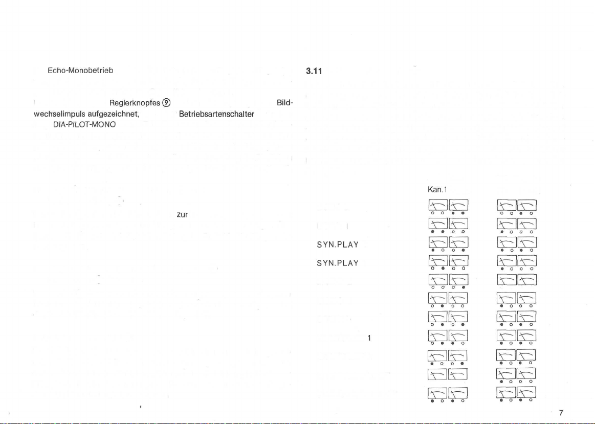
3.11
Betriebsartenschalter ®
Mit diesem Drehschalter können elf Betriebsarten eingeschaltet werden.
Die für die entsprechende Betriebsart belegte Spur und die eingeschal-
tete Aufnahme- oder Wiedergabefunktion wird von vier Leuchtdioden
angezeigt, die den Aussteuerungsinstrumenten zugeordnet sind. Leuchtet
eine dem Instrument zugeordnete Diode rot auf, so signalisiert das „auf
dieser Spur wird aufgenommen". Leuchtet eine Diode grün auf, so signalisiert das „diese Spur wird wiedergegeben". In der folgenden Aufstellung
kennzeichnen die ausgefüllten Kreise das Leuchten der entsprechenden
Anzeigediode.
Aufnahme
Kan.1
Kan.2
Wiedergabe
Kan.1 Kan.2
ECHO 2
ECHO 1
SYN.PLAY
SYN.PLAY 1
MONO 2
2
0*00
o o • o
MONO 1
STEREO
3.10 Taste AUFNAHME ®
Durch Drücken dieser Taste wird das Gerät in die Betriebsstellung „Auf-
nahme" gebracht. Die Taste bleibt nur dann eingerastet, wenn man aus
der Stellung STOP des Funktionswählers © in die Stellung PAUSE oder
START schaltet. In den Stellungen PAUSE und START ist die Taste gesperrt und kann nicht gedrückt werden.
MULTIPLAY
1
MULTIPLAY 2
MONO/DIA-PILOT
STEREO/DIA-PILOT
• o o o
Page 10
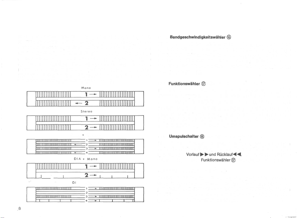
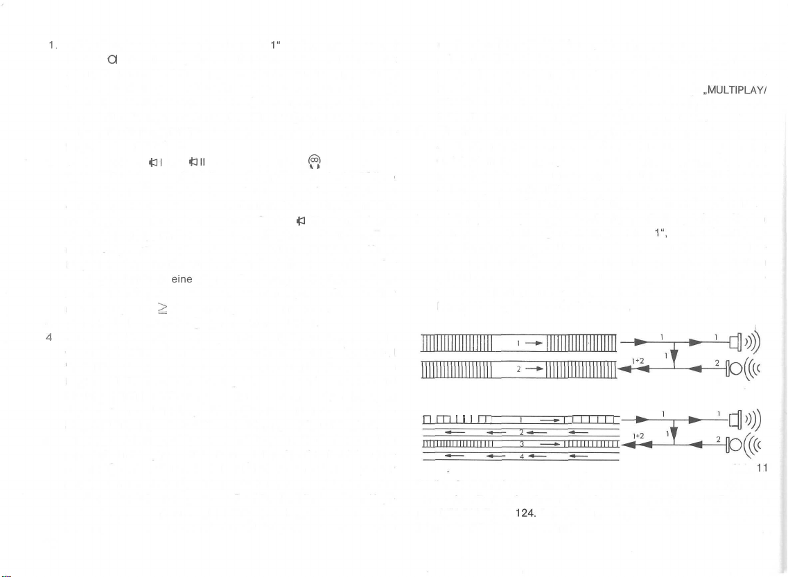
Die Lage der Spuren ist in den nachfolgenden Abbildungen dargestellt.
Die Ziffern kennzeichnen die Lage der Spuren, die Pfeilrichtungen kennzeichnen die Laufrichtung des Tonbandes. Durch Vertauschen der leeren
mit der vollen Bandspule wird nach Abspielen einer Spur die zugehörige
zweite Spur zum Abspielen vorbereitet, z.B. bei 2-Spur-Mono-Betrieb die
Spur 2 und bei 4-Spur-Mono-Betrieb die Spur 4 in Stellung MONO 1 des
Betriebsartenschalters. Bei Stereo-2-Spurbetrieb wird am Bandende auf
Rücklauf geschaltet; bei Stereo-4-Spurbetrieb werden am Bandende die
volle und die leere Bandspule miteinander vertauscht.
3.12
Bandgeschwindigkeitswähler®
Mit diesem Drehschalter wird eine der vier zur Verfügung stehenden Bandgeschwindigkeiten gewählt und gleichzeitig die Stromversorgung eingeschaltet. In den Stellungen 0 ist die Stromversorgung abgeschaltet. In der
Stellung VERSTÄRKER ist der Antriebsmotor ausgeschaltet, so daß der
Verstärkerteil als Mono- oder Stereo-HiFi-Verstärker verwendet werden
kann (s. auch Abs. 10).
3.13
Funktionswähler©
für STOP-PAUSE und START
Dieser Drehschalter dient zur Wahl der Bandlauffunktionen „STOP",
„PAUSE" und „START". Der Drehschalter kann nur betätigt werden, wenn
sich der Umspulschalter ® in der eingerasteten Mittelstellung befindet.
Durch Drehen des Schalters über die Stellung „START" hinaus wird die
automatische Bandendabschaltung ausgeschaltet. Eine sich im Bandein-
legeschlitz befindende Schaltfolie wird so mit der jeweils gewählten Band-
geschwindigkeit transportiert und aufgewickelt.
J
L
Mono + Stereo
DIA + Mono
Dl
A t Stereo
3.14
Umspulschalter®
für Vorlauf und Rücklauf
Dieser Schiebeschalter, der sowohl in der mittleren, als auch in der linken
und rechten äußeren Stellung einrastet, dient zum Einschalten des Umspulvorganges
tätigt werden, wenn der
Vorlauft
Funktionswähler©
^-und
Rücklauf-^
-^.
Der Schalter kann nur be-
in Stellung „STOP" steht.
3.15 Zählwerk mit Nullstelltaste ®
Durch Niederdrücken dieser Taste wird jede angezeigte Zahlenkombination gelöscht und es erscheint die Anzeige 0000. Es empfiehlt sich, vor
jeder Aufnahme die Nullstelltaste zu drücken, bzw. die Zahlenkombination
der Zählwerkanzeige zu notieren, um bei der Wiedergabe bestimmte Programmstellen schneller auffinden zu können.
Page 11
4. Anschluß des Gerätes an den Verstärker Ihrer HiFi-Anlage
Die folgenden Schaltbeispiele stellen die am häufigsten beim Aufbau einer HiFi-Anlage vorkommenden Geräteanordnungen und deren Verbindungen zueinander dar. Die in dem Abs. 12 enthaltenen technischen Angaben machen es dem Fachmann möglich,
zu wählen und die richtigen Verbindungen herzustellen.
auch
jede andere Anordnung
4.1 Anschluß von Geräten an Verstärker mit
Normbuchsen nach
Die Abbildung 7 zeigt schematisch den Anschluß des Tonbandgerätes an
einen HiFi-Verstärker mit Normanschlußbuchse nach DIN für Aufnahme
und Wiedergabe. Alle übrigen Tonquellen, wie Rundfunkgerät, Plattenspieler usw., werden an den entsprechenden Eingängen des Verstärkers
angeschlossen. Der Verstärker wird mit der Stereo-Tonleitung Typ K 541
an der Buchse £ des Tonbandgerätes angeschlossen. Damit ist auch die
Aufnahme aller mit dem Verstärker verbundenen Tonquellen während der
Übertragung durch die Anlage möglich. Die Taste „MICRO" (T) darf nicht
gedrückt sein.
Obwohl Mikrofone auch am Verstärker angeschlossen werden können,
empfiehlt sich der direkte Anschluß an der Buchse „Mikrofon" Q Ihres
Abb.
7
DIN
Tonbandgerätes. Nur bei Mikrofonaufnahmen wird dann die Taste
„MICRO" © gedrückt.
Es hat sich als zweckmäßig herausgestellt, besonders Mikrofonaufnahmen
in Stellung HINTERBAND der Taste ® über Kopfhörer zu überwachen.
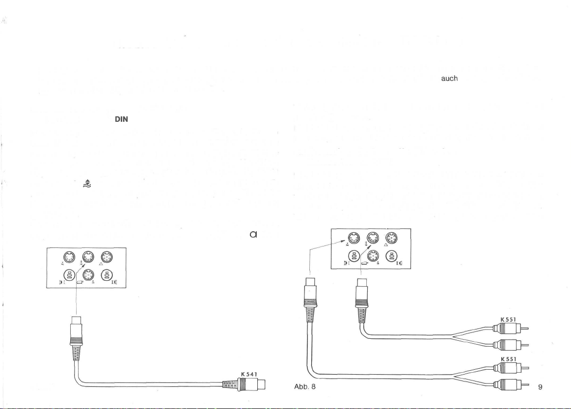
4.2 Anschluß von Geräten an Verstärker ohne
Normbuchsen nach DIN
Die Abbildung 8 zeigt schematisch den Anschluß des Tonbandgerätes an
einen HiFi-Verstärker ohne Normanschlußbuchsen nach DIN. Auch hier
werden alle übrigen Tonquellen, wie Rundfunkgerät, Plattenspieler usw.,
an den entsprechenden Eingängen des Verstärkers angeschlossen.
Während für Aufnahmebetrieb eine Verbindung vom Ausgang des Ver-
Page 12
stärkers für
rätes mit dem Kabel Typ K 551 hergestellt wird, erfolgt die Wiedergabeverbindung von der Buchse
Eingang für Tonbandgeräte des Verstärkers unter Verwendung eines
zweiten Kabels Typ K 551. Die gelbe Markierung der Kabelenden bezeichnet den linken und die rote Markierung den rechten Stereokanal.
Die Taste „MICRO" (T) darf nicht gedrückt sein, außer es soll eine Aufnahme mit dem Mikrofon über die Buchse „Mikrofon" Q erfolgen.
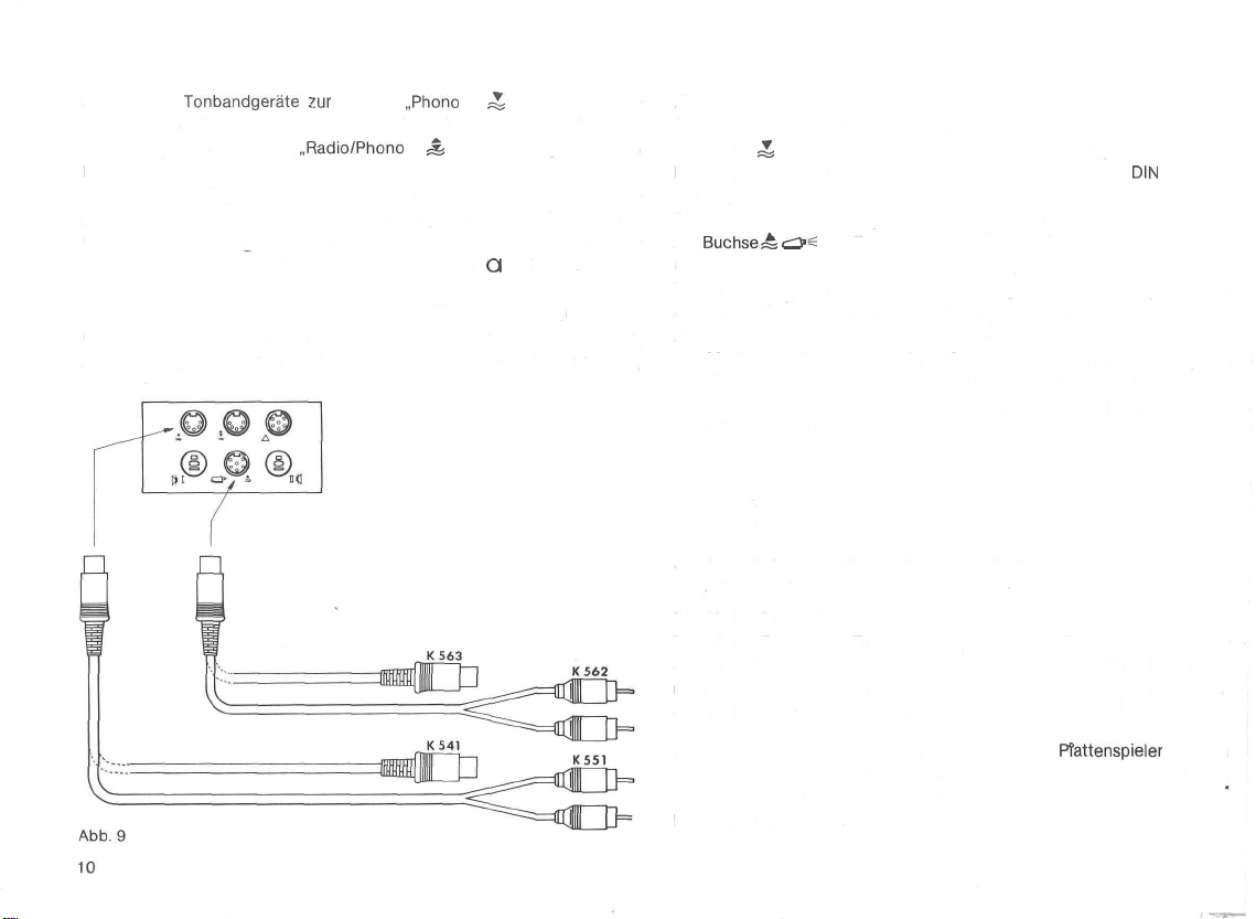
4.3 Anschluß des Gerätes an Verstärker mit Monitor-Eingang
Die Abbildung 9 stellt die Verbindung mit einem HiFi-Verstärker, der mit
einem Monitoranschluß und Monitorschalter zum wahlweisen Mithören
Tonbandgeräte
zur
Buchse
„Radio/Phono
„Phono
II" ^ des Tonbandge-
l" & des Tonbandgerätes zum
„Vor- und Hinterband" ausgestattet ist, dar. Die Aufnahmeverbindung erfolgt vom Ausgang für Tonbandgeräte des Verstärkers zur Buchse
„Phono II"
buchsen am Verstärker) bzw. K 541 (Normbuchsen nach
stärker).
Die Wiedergabeverbindung wird von der Buchse „Monitor des Verstärkers"
zur
(Cinchbuchsen am Verstärker) bzw. K 563 (Normbuchsen nach DIN am
Verstärker) hergestellt. Die gelbe Markierung aer Kabelenden bezeichnet
den linken Kanal und die rote Markierung den rechten Kanal. Bei dieser
Anschlußart kann die Tonbandaufnahme durch entsprechende Bedienung
des Monitorschalters am Verstärker (siehe dazu Bedienungsanleitung des
Verstärkers) wahlweise „Vor- oder Hinterband" über die Lautsprecher
der Anlage mitgehört werden, so daß sich der Anschluß eines StereoKopfhörers erübrigt.
4.4 Anschluß des Gerätes an Receiver, Musikschränke
Die Verbindung erfolgt, wie unter 4.1 beschrieben, mittels der StereoTonleitung Typ K 541. Ein Plattenspieler wird am Receiver, dem Musikschrank oder dem Rundfunkgerät direkt angeschlossen. Für Mikrofonaufnahmen wird der Anschluß des Mikrofones an der Buchse „Mikrofon" Q
des Tonbandgerätes vorgenommen und die Taste MICRO © gedrückt.
;J
des Tonbandgerätes mit einem Kabel Typ K 551 (Cinch-
Buchse«
oder Rundfunkgeräte
c^^
des Tonbandgerätes mit dem Monitorkabel Typ K 562
DIN
am Ver-
Tonbandaufnahmen vom Rundfunk oder dem
gemäß 4.3 Vor- oder Hinterband mitgehört werden. Mikrofonaufnahmen
werden zweckmäßigerweise über Stereo-Kopfhörer bei Mithören Vor- oder
Hinterband überwacht.
PTattenspieler
können
Page 13
5. Aufnahmebetrieb
Da die Qualität der Aufnahme im wesentlichen von der richtigen Einstellung der Aussteuerung abhängt, ist diesem Einstellungsvorgang besondere
Beachtung zu schenken (siehe hierzu auch Abs. 5.23).
5.1 Aufnahmebetrieb für Eilige
Eine Aufnahme ist wie folgt durchzuführen:
1. Gewünschte Tonquelle über die zugehörige Anschlußbuchse anschließen und einschalten. Alle anderen Tonquellen können ange-
schlossen bleiben, müssen aber abgeschaltet sein. (Mikrofoneingang
über die Taste © ein- bzw. ausschalten)
2. Sicherstellen, daß die Verbindung zur Netzsteckdose hergestellt ist.
3. Gerät auf die zur Aufnahme gewünschte Bandgeschwindigkeit einstel-
len. Damit ist die Stromversorgung eingeschaltet.
4. Tonband gemäß 1.7 einlegen und
Betriebsart einstellen, mit der die Aufnahme durchgeführt werden soll.
5. Taste „Aufnahme" ® niedergedrückt halten und Funktionswähler @
in Stellung „PAUSE" bringen.
6. Nullstelltaste ® des Zählwerkes drücken oder Zahlenkombination
der Zählwerkanzeige notieren, damit eine genaue Kennzeichnung der
Programmstellen für eine Archivierung zur Verfügung steht.
7. Mit den zugehörigen Aussteuerungsreglern @ und ® bzw. @ und
(D bei den lautesten Programmstellen 0 dB Anzeige an den beiden
Aussteuerungsinstrumenten (6) und © einstellen.
Betriebsartenschalter©
auf die
8. Funktionswähler® in Stellung START bringen. Der Bandtransport
setzt ein und die Aufzeichnung beginnt.
9. Die Aufnahme kann unterbrochen werden, wenn von START auf PAUSE
zurückgeschaltet wird; dabei bleibt das Gerät in Aufnahmebereitschaft.
10.
Nachdem die Aufnahme einer Bandseite bis zum Ende durchgelaufen
ist, volle rechte Bandspule mit der leeren linken Bandspule vertau-
schen und die Aufnahme, wie bereits beschrieben, auf der zweiten
Bandseite fortsetzen. (Bei 2-Spur-Stereo-Aufnahmen Tonband zurück-
spulen und ein anderes Band zu weiteren Aufnahmen einlegen).
11.
Bei Mikrofonaufnahmen empfiehlt es sich, die Aufnahmen nicht über
Lautsprecher sondern über Kopfhörer in Stellung HINTERBAND der
Taste MITHÖREN ® zu überwachen. Damit wird einerseits eine mög-
liche akustische Rückkopplung zwischen Mikrofon und Lautsprecher
vermieden, die sich durch Heul- und Pfeifgeräusche bemerkbar macht,
andererseits werden störende Nebengeräusche sofort erkannt und
können eventuell während der Aufnahme durch eine andere Anordnung des Mikrofones beseitigt werden.
12.
Nach beendeter Aufnahme sollte die Bandgeschwindigkeit, die Be-
triebsart und das Programm auf dem Vorspannband, der Bandspule
und der Bandbox vermerkt werden.
11
Page 14
5.2
Aufnahmebetrieb
5.21 Anschluß der Tonquellen
Der Anschluß der Tonquellen ist gemäß 2.1, 2.3 und 2.4 sowie unter Berücksichtigung der in Abs. 4 gemachten Angaben durchzuführen. Es
können alle Tonquellen angeschlossen bleiben, es darf aber immer nur
die Tonquelle eingeschaltet sein, die zur Aufnahme verwendet werden
soll. Wird beim Einstellen der Vollaussteuerung einer am Eingang
Phono l" angeschlossenen Tonquelle festgestellt, daß die Aussteuerungsregler @ und @ stets im untersten, kaum aufgeregelten Bereich bedient
werden müssen, so ist unter Berücksichtigung der Kontaktbelegung und
der Eingangsimpedanzen zu prüfen, ob beim Anschluß über einen im Fachhandel erhältlichen Überkreuz-Adapter (Stift 1 wird mit 3 und Stift 4 mit 5
vertauscht) an der Buchse „Phono II" bessere Bedingungen erreicht
werden. Entsprechend ist zu verfahren, wenn beim Anschluß an der
Buchse „Phono II" die Aussteuerungsregler (4) und © stets im obersten,
voll aufgedrehten Bereich bedient werden müssen. In diesem Fall ist der
Überkreuz-Adapter und der Eingang
Wenden Sie sich bitte an Ihren Fachhändler, wenn Sie mit der Lösung
von Anschlußproblemen nicht zurechtkommen.
5.22 Stromversorgung
Beim erstmaligen Anschluß des Gerätes sind die unter Abs.
Angaben besonders zu beachten. Vergessen Sie bitte nie vor einem Sicherungswechsel oder einer Umstellung auf eine andere Netzspannung die
Verbindung zur Steckdose zu trennen. Auch vor einer Reinigung des
für Interessierte
„Radio/Phono
„Radio/
l" zu verwenden.
1.4
gemachten
Gehäuses mit einem angefeuchteten Tuch ist stets der Netzstecker aus
der Steckdose zu ziehen. Bei eingeschalteter Bandgeschwindigkeit
müssen die
brennen.
5.23 Probeaussteuerung und Start einer Aufnahme
Unter einer Probeaussteuerung versteht man die Aussteuerungseinstel-
lung vor Beginn einer Aufnahme ohne daß dabei der Bandtransport ein-
geschaltet ist. Die Probeaussteuerung ist möglich, wenn ein Band gemäß
1.7 eingelegt ist und die Taste „Aufnahme" ® niedergedrückt und durch
Drehen des Funktionswählers ® von Stellung STOP in Stellung PAUSE
arretiert ist.
Nach Durchführung dieser Vorbereitungen wird mit den Aussteuerungsreglern (D und (D (bei Tonquellen, die am Eingang „Radio/Phono l"
angeschlossen sind) bzw. den Aussteuerungsreglern @ und © (bei Tonquellen, die am Eingang „Phono II" ^ angeschlossen sind)
schlag der Aussteuerungsinstrumente © und ® bei den lautesten Programmstellen auf 0 dB-Anzeige gebracht.
Diese Einstellung ist besonders sorgfältig durchzuführen, da eine zu hohe
Einstellung (Übersteuerung = Zeiger im roten Bereich) verzerrte Aufnahmen und damit auch verzerrte Wiedergabe zur Folge hat, während
eine zu schwache Einstellung (Untersteuerung = Zeiger stets wesentlich
unterhalb der 0
schen bemerkbar macht.
Durch Drehen des Funktionswählers ® von Stellung PAUSE in Stellung
START wird der Bandtransport in Betrieb gesetzt und die Aufnahme be-
ginnt.
Beleuchtungslämpchen
dB-Marke)
sich bei der Wiedergabe durch stärkeres Rau-
der Aussteuerungsinstrumente
£
der
Zeigeraus-
12
Page 15
6. Wiedergabebetrieb
6.1 Wiedergabebetrieb für Eilige
Die Wiedergabe kann direkt über die eingebauten Endstufen des Gerätes
erfolgen. Beim Hören über Kopfhörer können die eingebauten Lautsprecher wahlweise ein- oder ausgeschaltet werden (s. Abs. 2.2). Auch beim
Anschluß von externen Lautsprecherboxen können die eingebauten Lautsprecher wahlweise ein- oder ausgeschaltet werden (s. Abs. 2.5 und 2.6).
Die Wiedergabe ist wie folgt
1.
Tonband gemäß 1.7 einlegen und die Bandgeschwindigkeit über den
Drehschalter © einstellen, mit der die Aufnahme vorgenommen
wurde.
2.
Betriebsartenschalter®
bringen (s. Abs. 5.1 Punkt 12).
3. Funktionswähler © in Stellung START bringen.
4. Gewünschte Lautstärke der beiden Kanäle über die Regler ® und
@ bei Wiedergabe über die Geräteendstufe einstellen. Die Einstel-
lung der gewünschten Höhenwiedergabe erfolgt in diesem Fall über
den Regler ® , die der Tiefenwiedergabe über den Regler ® . Soll
die Wiedergabe über die Lautsprecherboxen der Verstärkeranlage vorgenommen werden, so sind all diese Einstellungen am Verstärker
selbst durchzuführen.
durchzuführen:
in
die
der Aufnahme entsprechende Stellung
5. Nach Abspielen einer Bandseite volle rechte mit leerer linken Spule
vertauschen. Band erneut einlegen und Wiedergabe wie beschrieben
starten.
6.2 Wiedergabebetrieb für Interessierte
Die Qualität der Wiedergabe ist in erster Linie abhängig von der Güte
der Aufnahme. Falsch ausgesteuerte Aufnahmen können auch von dem
besten Verstärker und den besten Lautsprecherboxen nicht mehr korrigiert werden. Die eingebauten
Stereobetrieb; lediglich Kontrollzwecken. Eine wesentlich bessere Kontrolle
ist durch Abhören mit einem Stereo-Kopfhörer möglich. Eine schwächere
Wiedergabe hoher Frequenzen läßt auf eine starke Verschmutzung des
Tonkopfes schließen (siehe hierzu Abs.
Bei stationärem Betrieb wird die Wiedergabe über Lautsprecherboxen,
die entweder an der
Verstärker Ihrer HiFi-Anlage angeschlossen sind, erfolgen. Im letzteren Fall
beachten Sie bitte die in Absatz 4 „Anschluß des Gerätes an den Verstärker Ihrer HiFi-Anlage" gemachten Angaben. Alle anderen Handhabungen
zur Inbetriebsetzung der Wiedergabe sind in der in Abs.
Reihenfolge vorzunehmen.
Geräutelautsprecher
11).
2X10
Watt Endstufe des Gerätes oder aber am
dienen; zumindest bei
6.1
beschriebenen
13
Page 16
7. Trick- und Effektaufnahmen
Die nachfolgend beschriebenen Aufnahmeverfahren können sowohl im
7.1 Echo bei
Mit Ihrem Gerät können Sie auch Hall- und Echoeffekte erzeugen. Durch
Wahl der Bandgeschwindigkeit sind Sie in der Lage vom Halleffekt bis
zum wirkungsvollen Echotrick überzugehen.
Mit den verschiedenen Bandgeschwindigkeiten erreichen Sie folgende
Wirkungen:
19
9,5
4,7
2,4
Eine Echoaufnahme geht wie folgt vonstatten:
1.
Durch Wahl der Bandgeschwindigkeit bestimmen Sie den gewünsch-
ten Effekt.
2. Tonquelle gemäß 2.1, 2.3 oder 2.4 anschließen. Bei Mikrofonaufnahmen Taste „MICRO" © drücken.
3. Je nachdem, auf welcher Spur Sie die Aufnahme machen wollen,
stellen Sie den Betriebsartenschalter ® auf Stellung „ECHO
nahme auf der Spur 1 bzw. 4) oder auf Stellung „ECHO 2" (Aufnahme
auf der Spur 2 bzw. 3). Wenn Sie Ihr Gerät in Zweispurtechnik betreiben, steht der Betriebsartenschalter © stets in Stellung „ECHO
4. Mit dem Regler „MICRO/RADIO l" (2) wird, wie bekannt, die richtige
Aussteuerung und mit dem Regler „MULTIPLAY/ECHO" ® die Stärke
des Effektes (Hall- bzw. Echo) eingestellt.
5. Das Mithören einer Echoaufnahme erfolgt am besten mit dem Kopfhörer Typ W 775, dessen Stecker in die Buchse „Kopfhörer" ^ so
14
Monoaufnahmen
cm/s Halleffekt
cm/s Echo
cm/s Echo mit längerer Nachhallzeit
cm/s Trickecho
1"
(Auf-
1".
Zweispur-als
eingesteckt wird, daß die eingebauten Lautsprecher abgeschaltet
sind (siehe 2.2). Die Taste „MITHÖREN" ® muß in Stellung „HINTERBAND" stehen.
6. Die Wiedergabe erfolgt in der gleichen Art wie bei normalen Aufnahmen. Der „Betriebsartenschalter" ® kann entweder in der Stellung „ECHO" stehen oder wird auf die entsprechende Spur der Echoaufnahme gestellt.
7.2 Echo bei Stereoaufnahmen
Über das Monitorkabel K 563 besteht die Möglichkeit Echoaufnahmen
bei Betriebsstellung „STEREO" durchzuführen.
Im einzelnen geht dies wie folgt vonstatten:
1.
Betriebsartenschalter ® in Stellung „STEREO" bringen.
2. Gerät auf Aufnahme schalten.
3. Monitorkabel K 563 von Buchse
Buchse ^ (Spoliger
4. Das mit Hall zu versehende Signal entweder über die Buchse
oder bei gedrückter Taste „MICRO" © über die Buchse Q einspeisen und mit den Reglern „MICRO/RADIO" @ und (3) aussteuern.
Taste „MITHÖREN" (8) darf nicht gedrückt sein. Die Regelung der
Stärke des Echosignals erfolgt mit den Reglern
5. Dient die Buchse
das Monitorkabel K 563 auch an die Buchse
werden. In diesem Fall erfolgt die Regelung des Originaltons mit den
Reglern „PHONO" © und © und die Stärke des Echosignals mit
den Reglern „MICRO/RADIO" © und ® .
auch im Vierspur-Betrieb durchgeführt werden.
ö5?
-4
(6poliger Stecker) an
Stecker) anschließen.
„PHONO" @ und ©
-J
für die Aufnahme des Originalsignals, so kann
-^
angeschlossen
£
Page 17
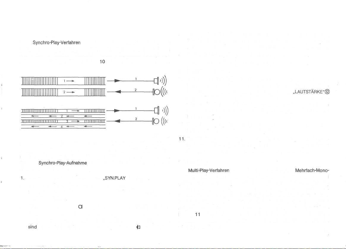
7.3 Synchroplay
Beim
Synchro-Play-Verfahren
zeitig auf der dazugehörigen Parallelspur eine Aufnahme gemacht. Damit
lassen sich verschiedene Trickeffekte erzielen. Sie können z.B. mit sich
selbst ein Duett singen. Die Abbildung
wird eine Spur wiedergegeben und gleich-
10
zeigt den Vorgang schematisch.
HD
((t«
d
Abb.
10
Besonders für den Dia- und Film-Amateur wird das Synchro-Play-Verfahren
von größtem Nutzen sein. Die durchdachte Konstruktion des Gerätes
macht es Ihnen leicht, diese effektvollen Trickaufnahmen herzustellen.
Für eine
Synchro-Play-Aufnahme
dienungshandgriffe aus:
1.
Betriebsartenschalter © in Stellung
2. Taste „MITHÖREN" (8) in Stellung „VORBAND" bringen.
Beide Knöpfe des Doppelreglers „LAUTSTÄRKE" @ und © ganz
nach links drehen.
3. Mikrofon an Buchse Q anschließen, Taste „MICRO" ® drücken.
4. Kopfhörer, z.B. magnetischen Kleinhörer Typ W 214 oder den Stereo-
Kopfhörer Typ W 674 bzw. W 774 (die Stecker des Stereo-Kopfhörers
sind
vor Anschluß aufeinander zu stecken) an Buchse
führen Sie der Reihe nach folgende Be-
„SYN.PLAY
1" bringen.
+3
l anschließen.
5. Jetzt machen Sie, wie bekannt, die erste Aufnahme über Mikrofon.
Die Aussteuerung wird mit dem oberen Knopf des Doppelreglers
„MICRO/RADIO" @ vorgenommen. Das linke Instrument © zeigt an.
6. Tonband bis zum Anfang der Aufnahme zurücklaufen lassen.
7. Betriebsartenschalter © in Stellung „SYN.PLAY 2" bringen.
8. Kopfhörer aufsetzen.
9. Taste „AUFNAHME" ® drücken, Aufnahme starten. Während Sie im
Kopfhörer die Wiedergabe der ersten Aufnahme hören, wobei die
Lautstärke mit dem oberen Knopf des Doppelreglers
eingestellt wird, nehmen Sie nun über Mikrofon die zweite Aufnahme
taktgerecht dazu vor. Die Aussteuerung stellen Sie wieder mit dem
oberen Knopf „MICRO/RADIO" @ ein, jetzt zeigt jedoch das rechte
Instrument (7) an.
10. Nach Beendigung der Aufnahme lassen Sie das Tonband zurücklaufen und ziehen den Stecker des Kopfhörers heraus.
11.
Zur Wiedergabe einer Synchro-Play-Aufnahme bringen Sie den Be-
triebsartenschalter © in Stellung „STEREO", die Taste „MITHÖREN"
® in Stellung „HINTERBAND" und starten den Bandablauf.
7.4 Multiplay
Das
Multi-Play-Verfahren
Trickaufnahmen durch Überspielung einer Spur auf die andere, wobei
gleichzeitig noch eine weitere Aufnahme zugesetzt wird. Durch mehrfache
Wiederholung des Vorganges entsteht dann als Ergebnis z.B. ein EinmannSextett. Voraussetzung für die Multiplayaufnahme ist, daß die beiden
benötigten Tonspuren (bei 2-Spurbetrieb die Spuren 1 und 2 und bei
4-Spurbetrieb die Spuren 1 und 3 bzw. 2 und 4) unbespielt sind. Die Abbildung
11
zeigt den Vorgang schematisch. Dank der ausgereiften Konstruktion des Gerätes können Sie diese Betriebsart leicht und mühelos
wie folgt vornehmen:
ermöglicht die Herstellung von
„LAUTSTÄRKE"®
Mehrfach-Mono-
15
Page 18
1.
Betriebsartenschalter © auf „MULTIPLAY
Buchse Q anschließen (beim Anschluß eines Stereo-Mikrofones ist
automatisch nur das Mikrofonsystem für den Kanal 1 (linker Kanal)
wirksam.) und Taste „MICRO" © drücken. Taste „AUFNAHME" ®
gedrückt halten und Funktionswähler @ von Stellung „STOP" in Stellung „PAUSE" bringen. Die Taste „MITHÖREN" ® muß bei laufendem
Tonband in Stellung „HINTERBAND", bei stehendem Tonband in Stellung „VORBAND" stehen.
2. An den Buchsen
Typ K 633 wird je ein „Kopfhörer" (z.B. Typ W 674 oder W 774) so
angeschlossen, daß die eingebauten Lautsprecher abgeschaltet werden (s. 2.2, 2.7 und 2.8). Dabei ist der rote Stecker des Kopfhörers
auf den gelben aufzustecken. Der an der Buchse
K 633 (gelbe Kupplung) angeschlossene Kopfhörer dient dem „Ton-
meister", der an der Buchse 43 l bzw. am Adapter K 633 (rote Kupp-
lung) dient dem Künstler zum Mithören der Aufnahme. Um bei großer
Wiedergabelautstärke
zu vermeiden dürfen beim benutzen der Buchse 43 l und 43 II nur Hörer
mit einer Impedanz
3. Regler MULTIPLAY/ECHO © ganz nach links drehen.
4
Nach Wahl der Bandgeschwindigkeit (für Multiplayaufnahmen sind die
Geschwindigkeiten 19 cm/s oder 9.5 cm/s am besten geeignet) und
Einstellung der Aussteuerung über den oberen Drehknopf @ des
Reglers „MICRO/RADIO" in Stellung „VORBAND" wird nun zuerst auf
Stellung „HINTERBAND" umgeschaltet und dann der Bandtransport
durch Drehen des Funktionswählers ® von Stellung „PAUSE" in Stel-
lung „START", eingeschaltet. Die Aufzeichnung auf Spur 1 beginnt.
5. Ist die Aufzeichnung auf Spur 1 beendet, spulen Sie das Tonband bis
zum Aufnahmebeginn zurück. Dann stellen Sie den Betriebsartenschalter ® auf „MULTIPLAY 2". Der Künstler setzt seinen Kopfhörer
auf; die Aufnahmetaste ® wird gedrückt und dann der Bandtransport
für die zweite Aufnahme gestartet. Der Künstler hört in seinem Kopf-
hörer die erste Aufnahme (Lautstärkeeinstellung mit dem oberen
Knopf ® des Doppelreglers „LAUTSTÄRKE") und kann nun taktge-
43l
und
43II
oder an der Buchse
eine
mögliche Zerstörung der Kopfhörersysteme
Ja
200 Ohm angeschlossen werden.
1"
stellen. Mikrofon an der
fj
über das Kabel
<3
II bzw. am Adapter
16
recht dazu die zweite Darbietung vornehmen. Der Tonmeister hört in
seinem Kopfhörer beide Darbietungen, wenn er in Stellung „HINTERBAND" die neue Aufnahme über den Regler @ und die zur Überspielung kommende erste Aufnahme über den Regler ©
ECHO" aussteuert. Damit ist es möglich, das Lautstärkeverhältnis
beider Darbietungen zueinander beliebig zu beeinflussen.
6. Für eine weitere zusätzliche Aufnahme wird das Tonband zurückgespult, der Betriebsartenschalter © auf „MULTIPLAY 1" geschaltet
und der Aufnahmevorgang wie bereits beschrieben wiederholt. Kommt
noch eine weitere Aufnahme dazu, so schalten Sie den Betriebsartenschalter © auf „MULTIPLAY 2", spulen das Tonband zurück und so
wechselnd fahren Sie fort, bis die Multiplayaufnahmen beendet sind.
7. Bei der späteren Wiedergabe von Multiplayaufnahmen bringen Sie den
Betriebsartenschalter © in Stellung „MONO
aufnahme in Stellung „MULTIPLAY 1" beendet wurde. Stand der Betriebsartenschalter ® am Ende der Multiplayaufnahme in Stellung
„MULTIPLAY 2", so schalten Sie zur Wiedergabe auf „MONO 2". Die
weitere Bedienung unterscheidet sich nicht von der bereits beschrie-
benen Wiedergabe normaler Aufnahmen.
11
111
i
i i
rr
Wollen Sie Multiplayaufnahmen stereofon durchführen, so benötigen Sie
ein zweites Tonbandgerät und ein Mischpult, wie z.B. das UHER Mischpult MIX 500 Typ A
leitung des Mischpultes beschrieben.
124.
MINI
Der Aufnahmevorgang ist in der Bedienungsan-
1",
„MULTIPLAY/
wenn die Multiplay-
l'»)
Abb.
11
Page 19
8. Diapilot
Sind Sie
das Gerät zur vollautomatisch ablaufenden tönenden Bildschau, denn das
Tonbandgerät übernimmt nicht nur den Text und die Tonuntermalung,
sondern steuert auch den Bildwechsel des Projektors. Der Dia-Pilot ar-
beitet bei allen Bandgeschwindigkeiten mit Ausnahme von 2,4 cm/s. Es
sind keine weiteren Zusatzgeräte erforderlich.
Sie brauchen nur folgende wenige Handgriffe auszuführen:
1.
2. Je nachdem, ob die Vertonung in Mono oder Stereo erfolgen soll
3. Haben Sie die Tonaufnahme beendet, so lassen Sie das Tonband
Besitzer
Tonbandgerät und Projektor betriebsfertig machen. Am Projektor ist
dessen Fernsteuerkabel anzuschließen.
(Stereovertonung ist nur möglich, wenn Sie Ihr Gerät in Vierspur-
technik betreiben), schalten Sie den Betriebsartenschalter © auf
„MONO 1" bzw. „STEREO". Bei der Tonaufnahme erfolgt die Bedienung des Gerätes wie in Abs. 5. Aufnahmebetrieb beschrieben.
An der Buchse
ein Tonbandgerät anschließen. Damit ist ein Mischen von Musik oder
Geräuschen
Soll Ihre tönende Bildschau besonders schön werden, dann machen
Sie vorher ein kleines Drehbuch, anhand dessen die Vertonung in
Text und Ton erfolgt. Die richtige Aussteuerung des Textes, den Sie
über Mikrofon aufsprechen, regeln Sie mit dem Regler
RADIO" © (bzw. @ und © ), während mit dem Regler „PHONO" ©
(bzw. @ und © ) Musikuntermalung oder Geräusche eingemischt
werden können. Den Bildwechsel des Projektors betätigen Sie mit der
Fernsteuerleitung, so daß immer das richtige
Vertonung erscheint.
zurücklaufen, bringen das Magazin des Projektors in Anfangstellung
und entfernen das Fernsteuerkabel vom Projektor. Dann lösen Sie die
Verbindungen aller etwa angeschlossenen Tonquellen und verbinden
eines automatischen Dia-Projektors, so verhilft Ihnen
£.
können Sie auch noch einen Plattenspieler oder
mit dem
Doppelregler
„PHONO"®
und©
möglich.
Bild
zu der jeweiligen
„MICRO/
den Fernsteueranschluß des Projektors mit der Buchse
Tonbandgerätes, durch das Kabel Typ K
4. Erfolgt die Vertonung im
so schalten Sie den Betriebsartenschalter © auf „DIA-PILOT MONO"
und starten den Bandlauf erneut für Aufnahme. Handelt es sich um
eine Stereo-Vertonung, wird der Betriebsartenschalter ® in Stellung
„DIA-PILOT STEREO" gebracht. Sie hören jetzt die Wiedergabe der
Vertonung. Jeweils wenn ein Bildwechsel erfolgen soll, drücken Sie den
Knopf „MULTIPLAY/ECHO" © . Der Projektor wechselt das Bild, und
gleichzeitig wird auf Spur 4 ein Steuerton verzeichnet, der bei der
späteren Wiedergabe den Bildwechsel des Projektors automatisch
auslöst.
5. Wenn alle Bilder durchgelaufen sind, spulen Sie das Tonband zurück
und bringen das Magazin des Projektors in Anfangstellung. Jetzt kann
Ihre Dia-Vorführung, von Ihrem
ablaufen. Den Betriebsartenschalter © bringen Sie in Stellung
„DIA-PILOT MONO" bzw. „DIA-PILOT STEREO", starten den Bandlauf
für Wiedergabe und wählen die gewünschte Klangfarbe und Lautstärke an Ihrem Verstärker
„HÖHEN/TIEFEN"
Noch ein Tip;
Sollte es vorkommen, daß Sie sich beim Aufnehmen des Steuertons
„vertippen" oder daß Sie in Ihre Serie noch ein weiteres Bild nachträglich einfügen wollen, so brauchen Sie nur das Tonband nochmals, wie
unter 3. und 4. beschrieben, durchlaufen zu lassen und an jeder gewünschten Stelle, wenn ein Bildwechsel erfolgen soll, den Knopf des
Reglers „MULTIPLAY/ECHO" © zu drücken. Die vorher aufgezeichneten
Steuertöne werden automatisch gelöscht und durch die neuen ersetzt.
Mono-Verfahren
.Die
Klangfarbe kann mit dem Doppelregler
® und ® am Gerät gewählt werden.
911.
(Zweispur oder Vierspur),
Tonbandgerät
automatisch gesteuert,
O"=
17
Page 20
9. Anschluß von Zusatzgeräten und Anpassen des Gerätes
an die jeweiligen Betriebsbedingungen
9.1 Betrieb mit dem Akustomat F 411
Der Akustomat F
und stoppt vollkommen selbsttätig bei Betrieb in Stellung „MONO 1" den
Bandlauf bei Beginn und Beendigung einer Aufnahme. Der Anschluß erfolgt an der mit A bezeichneten Buchse. Weitere Einzelheiten ersehen
Sie aus der Bedienungsanleitung, die dem Akustomat F
9.2
Betrieb über die Schaltuhr A 403
Die Stromzufuhr zu Ihrem Tonbandgerät erfolgt über die Schaltuhr A 403.
Zur Wiedergabe sind der Betriebsartenschalter © und der Geschwindig-
keitswähler ® in die gewünschte Stellung zu bringen und der Funktionswähler ® in Stellung „START".
Soll über die Schaltuhr eine Aufnahme gesteuert werden, so ist
lich die Tonquelle über die Schaltuhr anzuschließen. Die Aufnahmebereitschaft des Gerätes wird durch Drücken und Einrasten der Taste „AUF-
NAHME" ® hergestellt.
9.3 Aufnahme von Telefongesprächen mit dem Telefonadapter A 261
Der galvanische Telefonadapter A 261 wird über die Buchse ^ an Ihr
Tonbandgerät angeschlossen. Der Anschluß des Adapters an Ihr Telefon
muß durch die Post erfolgen.
Die Aufzeichnung erfolgt in Stellung „Mono 1" des Betriebsartenschalters © ; ansonsten ist wie unter Abs. 5 „Aufnahmebetrieb" beschrieben,
zu verfahren. Zweckmäßigerweise ist eine Probeaussteuerung mit dem
oberen Regler des Doppelreglers „MICRO/RADIO" @ durchzuführen.
411
ist ein elektronisch-akustischer Schalter. Er startet
411
beiliegt.
zusätz-
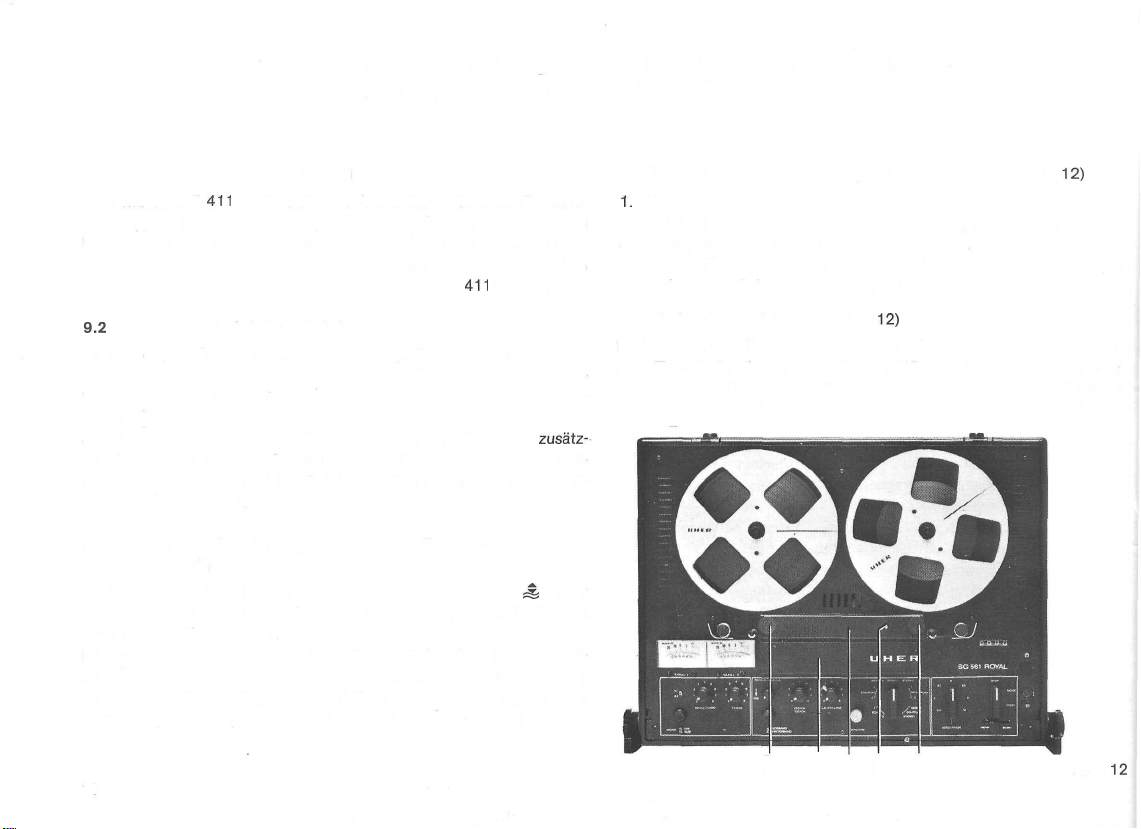
9.4 Auswechseln des Tonkopfträgers Z 345 bzw. Z 346 (Abb.
1.
Vordere Abdeckkappe (A) nach oben abziehen.
2. Durch Linksdrehen die beiden Rändelmuttern (B) abnehmen.
3. Tonkopfträger (C) lotrecht nach oben abziehen.
4. Anderen Tonkopfträger aufstecken, mit den Rändelmuttern fest ziehen
und vordere Abdeckkappe wieder aufsetzen.
9.5 Wiedergabekopfeinsteller (Abb.
In einer Bohrung (D) an der Oberseite des Tonkopfträgers befindet sich
eine Einstellschraube, mit der sich der Wiedergabekopf in bestimmten
Grenzen nach links und rechts aus der senkrechten Normalstellung
schwenken läßt, so daß auch Tonbänder wiedergegeben werden können,
12)
12)
18
B A C D B
Abb.
12
Page 21
die mit anderen Maschinen, deren Aufnahmeköpfe von der Normalstellung
abwichen, aufgenommen wurden.
Die Einstellung erfolgt mit einem antimagnetischen Schraubenzieher auf
beste Höhenwiedergabe nach Gehör. Dazu obere Hälfte des Doppelreglers ® auf volle Höhenwiedergabe einstellen.
Die richtige Einstellung in Übereinstimmung mit dem Aufnahmekopf des
eigenen Gerätes ist dann wieder hergestellt, wenn beim Mithören einer
Aufnahme hinter Band die beste Höhenwiedergabe erreicht wird. Es ist
vorteilhaft, diese Einstellung bei der Bandgeschwindigkeit 19 cm/s vorzunehmen.
9.6 Verwendung der Reduzierkupplung K 853
Die Reduzierkupplung K 853 dient zum Anschluß von
an Ihr Stereo-Tonbandgerät. Sie wird immer dann benötigt, wenn die
Mono-Tonquelle
direkten Anschluß der
9.7 Schmalfilmvertonung
Mit Ihrem Stereo-Tonbandgerät besitzen Sie die Möglichkeit, synchrone,
impulsgesteuerte Schmalfilmvertonungen nach dem sogenannten Zwei-
band-Verfahren
Ihrem Tonbandgerät eingebaut ist, ist über die Kontakte 4 und 6 (6 =
Masse) der
Wiedergabe der Synchron-lmpulse bei der Vertonung.
9.8 Löschen ohne Neuaufnahme
Bei jeder Aufnahme wird automatisch eine etwa vorhandene frühere Aufzeichnung gelöscht. Soll in besonderen Fällen nur gelöscht werden, so
wird das Gerät genauso wie bei einer Aufnahme bedient. Die Aussteuerungsregler @, (3) ,0 und © werden bis zum linken Anschlag zugedreht.
9.9 Rapid-Löschen
In besonderen Fällen kann es erwünscht sein, eine Aufnahme schnell
unkenntlich zu machen. Hierzu dient die Rapid-Löscheinrichtung. Es ist
lediglich notwendig, während des schnellen Vor- bzw. Rücklaufs des
Bandes die Taste „Aufnahme" @ zu drücken. Die Aufzeichnung wird
dann durch einen hohen Pfeifton unkenntlich gemacht.
eine dreipolige Normanschlußbuchse besitzt, die den
Spoligen
durchzuführen. Der Tonkopf, der zur Diasteuerung in
Buchse
<Z2^£
Stereo-Tonleitung K 541 nicht zuläßt.
herausgeführt und dient zur Aufnahme und
Mono-Tonquellen
10.
Verwendung des Tonbandgerätes als
HiFi-Stereo-Mischverstärker
Das Laufwerk des Gerätes ist in Stellung VERSTÄRKER des Bandgeschwindigkeitschalters © abgeschaltet, so daß der Verstärkerteil mit
seinen Stereo-Eingängen auch allein als Mischverstärker betrieben werden
kann. Es können entweder zwei Stereo-Plattenspieler mit eingebautem
Entzerrervorverstärker oder zwei Stereo-Cassetten- oder Tonbandgeräte
über die Buchse
schlossen werden.
Nachdem die gewünschten Tonquellen angeschlossen sind, wird bei den
lautesten Programmstellen mit den Reglern
entsprechenden Aussteuerungsinstrumenten © und © der maximale
Zeigerausschlag auf 0 dB-Anzeige eingestellt. Das erfolgt nacheinander
für jeden Eingang getrennt. Dann wird die gewünschte Höhen-, Tiefen-
und Lautstärkeeinstellung
VORBAND des Schalters MITHÖREN ® vorgenommen. Jetzt kann ein
Ausblenden der ersten und Einblenden der zweiten Tonquelle durch Aufund Zuregeln der Aussteuerungsregler @ und @ bzw. (4) und © durchgeführt werden. Soll zusätzlich eine Mikrofondurchsage erfolgen, so kann
immer dann der Mikrofoneingang über die Taste MICRO © eingeschaltet
werden, wenn gerade eine Wiedergabe, der über die Buchse „Phono II"
angeschlossenen Tonquelle erfolgt. Zum Einblenden eines Mono-Mikrofones wird der Regler © und zum Einblenden eines Stereo-Mikrofones
werden die Regler @ und @ verwendet. Es ist zweckmäßig, die Stellung
der Aussteuerungsregler für jede Tonquelle zu markieren. Bei Mikrofondurchsagen kann es zu akustischer Rückkopplung kommen, die sich durch
einen Pfeif- oder Heulton bemerkbar macht. Die Ursache liegt in einem zu
starken Auftreffen des von den Lautsprechern kommenden Schalles auf
das Mikrofon. In diesem Fall ist der oder die Aussteuerungsregler nur
soweit hochzuregeln, daß noch kein Pfeifton erscheint oder aber der Ab-
stand zwischen Mikrofon und Lautsprecher zu vergrößern.
„Radio/Phono
mit
l" £ und die Buchse
den Reglern ® , @ , © und ® in Stellung
„Phono
II" ^ ange-
@,
® , (4) und © an den
-J,
19
Page 22
11.
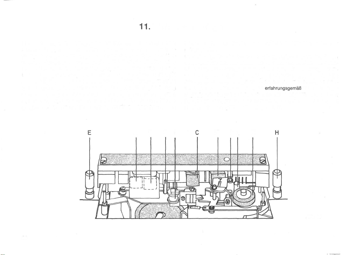
Wartung und Pflege
Die Ausrüstung aller wichtigen Lagerstellen mit selbstschmierenden
Sintermetall-Lagern macht ein Ölen der Geräte auf Lebensdauer überflüssig. Die Pflege und Wartung erstreckt sich daher vorwiegend auf Kontroll- und Reinigungsarbeiten in gewissen Zeitabständen. Hierfür stehen
unsere Kundendienststellen zur Verfügung. Die von Zeit zu Zeit erforder-
liche Reinigung der Tonköpfe - Sie erkennen dies daran, daß zum Beispiel
die Wiedergabe, besonders der hohen Töne, nachläßt - können Sie leicht
selbst vornehmen. Hierzu wird zunächst die vordere Tonkopfabdeckung
nach oben gezogen, die Magnetköpfe A, B, C, D, die Bandführungen E, F,
G, H. Bandrolle l, Andruckrolle K und die Tonwelle L sind dann leicht zugänglich (s. Abb. 13) und können mit dem UHER Spezial Reinigungssatz
A B F l
Z 172 von etwa anhaftenden Staub- und Bandschichtablagerungen ge-
reinigt werden.
Ihr Tonbandgerät stellt ein hochentwickeltes Präzisionsgerät dar, dessen
einwandfreie Funktion von dem exakten Arbeiten mechanischer und elektrischer Bauteile abhängt. Bei der Konstruktion dieser wichtigen Teile
wurde auf größte Betriebssicherheit geachtet. Sollten einmal irgendwelche
Störungen auftreten, so empfiehlt es sich, in jedem Fall einen spezialisierten Fachmann zu Rate zu ziehen, der
ringfügigen Fehlerquellen sicher erkennt und beseitigt. Wir warnen davor,
irgendwelche Eingriffe durch Nicht-Fachleute vornehmen zu lassen, weil
damit meistens nur größerer Schaden entsteht.
erfahrungsgemäß
die meist nur ge-
D G L K
Abb.
13
20
Page 23
12.
Hinweise für den Fachhändlerund technisch Interessierte
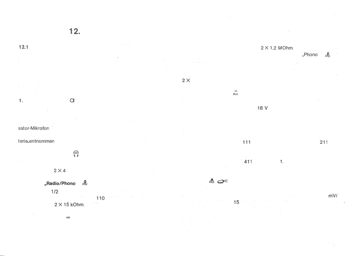
12.1
Kontaktbelegung, Ein-, Ausgangswiderstände
und Ein-, Ausgangsspannungen
Bei einer eventuell erforderlichen Verlängerung der Stereo-Tonleitung
Typ K 541 sind zur Vermeidung von Verlusten im Bereich hoher Fre-
quenzen bei der Aufnahme und der Wiedergabe die Ausgangsimpedanz
der Tonquelle, die Eingangsimpedanz des Wiedergabegerätes sowie die
Kabelkapazität zu berücksichtigen.
1.
Buchse „Mikrofon"
An den Stiften 3/2 und 5/2 (2 = Masse) dieser Buchse dürfen Eingangsspannungen zwischen 0,12 mV und 70 mV liegen. Neben allen nieder-
ohmigen dynamischen Mikrofonen kann auch das UHER Elektret-Konden-
sator-Mikrofon
für das Kondensatormikrofon wird aus der im Mikrofon eingebauten Bat-
terie-entnommen
2. Buchse „Kopfhörer"
Die maximale Ausgangsspannung an den Stiften 4/2 und 5/2 (2 und 3 =
Masse) betragen
Typ M 645 angeschlossen werden. Die Stromversorgung
ö
(siehe Bedienungsanleitung des Mikrofones).
^
2X4
V; die Innenwiderstände betragen 2 X ca. 200 Ohm.
Die Eingangswiderstände betragen
nungen über 1,5 V ist es empfehlenswert den Eingang
verwenden.
Bei der Wiedergabe beträgt die Ausgangsspannung an den Stiften 3/2
und 5/2 (2 = Masse) 2 X ca. 600 mV. Der Innenwiderstand beträgt dann
2X
15kOhm.
4. Buchse „Phono II"
An den Stiften 3/2 und 5/2 (2 = Masse) dieser Buchse dürfen Eingangsspannungen zwischen 200 mV und
betragen 2 X 50 kOhm.
5. Buchse A
Über die Stifte 4 und 3 (3 = Masse) wird die Betriebsstellung PAUSE
vom Handfernschalter Typ F
eingeschaltet.
Die Versorgungsspannung von 26 V (Innenwiderstand 390 Ohm) zum Be-
trieb des Akustomaten Typ F
Kanals wird an Stift 2, das des rechten Kanals an Stift 5, geführt.
—,
2X1,2MOhm.
18V
liegen. Die Eingangswiderstände
111
bzw. vom Fußfernschalter Typ F
411
liegt an Stift
Bei Eingangsspan-
1.
Das NF-Signal des linken
„Phono
II"
211
-^
zu
aus
3. Buchse
An den Stiften
spannungen zwischen 1,5 mV und
stände betragen
es empfehlenswert unter Verwendung eines Überkreuzsteckers an den
Stiften 3/2 und 5/2 (2 = Masse) einzuspeisen (Eingang „Radio/Phono l").
Die Eingangsspannungen dürfen dann zwischen 40 mV und 2,8 V liegen.
„Radio/Phono
1/2
2X15
l"
£
und 4/2 (2 = Masse) dieser Buchse dürfen Eingangs-
110
mV liegen. Die Eingangswider-
kOhm.
Bei Eingangsspannungen über 70 mV ist
6. Buchse
An Stift 1 dieser Buchse liegt der Monitor-Ausgang des linken Kanals und
an Stift 5 der des rechten Kanals (Ausgangsspannung 2 X ca. 600
Innenwiderstand 2 X ca.
der Steuerimpulse bei der Schmalfilmvertonung an die Stifte 4 und 6 (6 =
Masse) herausgeführt. Über die Stifte 2 und 3 wird der Bildwechsel am
Dia-Projektor gesteuert.
=4
<^2f-
15
kOhm). Der Dia-Pilot-Kopf ist zur Aufzeichnung
mV/
21
Page 24

12.2
Technische Daten
Aufzeichnung:
Bandgeschwindigkeiten:
Frequenzumfang:
Max. Spulendurchmesser:
Tonhöhenschwankungen
(DIN 45507):
Geräuschspannungsabstand:
(DIN 45500)
Übersprechdämpfung:
Generatorfrequenz:
Löschdämpfung:
Vierspur oder wahlweise Zweispur
(durch austauschbaren Tonkopfträger (Mono- und Stereo-Aufnahme
und -Wiedergabe.
19
cm/s
9,5
cm/s
4,7
cm/s
2,4
cm/s
19
cm/s:
9,5
4,7
cm/s:
cm/s:
20-20000 Hz
20-1
5000
Hz
20- 9000 Hz
18cm
19
cm/s:
9,5
cm/s:
4,7
cm/s:
19 cm/s: ;>67dB
9,5
4,7
;>
60 dB Mono
^
45 dB Stereo
ca
100
19
cm/s:
cm/s:
cm/s:
kHz
iä
<;
0,05
%
^
0,10%
S
0,20
%
2-Spur 4-Spur
^
66 dB
^
65 dB
72
dB
^
65
dB
^
64
dB
^ 61 dB
Eingänge: Mikro
Ausgänge:
Aussteuerungskontrolle:
Mithören:
Bandendabschaltung:
Aufnahme- und Wiedergabe:
Ausgangsleistung:
Stromart:
Netzspannungen:
Abmessungen:
Gewicht:
Pegelanzeige bei Wiedergabe an beiden Instrumenten
Alle Daten werden entsprechend den durch die deutschen Normen (DIN)
festgelegten Meßvorschriften für Magnettongeräte angegeben.
(B X H X T)
0,12
Radio (gemessen bei Stereo)
Phonol
40mV-2,8V/1,2MOhm
Phonoll
200mV-18V/50kOhm
Kopfhörer: 4 V/200 Ohm
Monitor: ca. 600
Dioden:
ca. 600
2 Anzeigeinstrumente mit
vor Band oder hinter Band mit
Kopfhörer und Lautsprecher in Stereo
elektronisch
Anzeige durch LED
2 X
10
Watt Sinusleistung an 4 Ohm
Wechselstrom 50 Hz,
umrüstbar auf 60 Hz
110-150,
ohne Haube
mit Haube
13,1
kg
mV-70
mV/2
1,5mV-110mV/15kOhm
mV/15
kOhm
mV/15
kOhm
dB-Skala
220-240V
46,0X18,3X35,5
46,0 X 19,2X35,5
—
kOhm
cm
cm
22
Page 25

Contents
1 . Setting Up
1.1 Air
1.2 Operating Position
1
.3
Extension
1
.4
A.C. Mains Connection, Operating Voltage and
Mains Fuse
1
.5
Attaching the
1
.6
Attaching and Removing the Transparent Dust Cover
1.7 Loading
2. Socketry
2.1 Microphone
2.2
Headphones
2.3 Phono Input II
2.4 Radio/Phono l
2.5 Remote Control Socket A
2.6
Slide
2.7 Left Loudspeaker Output
2.8 Right Loudspeaker Output
3. Controls and Their Functions
3.1 MICRO
3.2 Separate-Channel Level Controls @ and © for
MICRO and Radio/Phono l Inputs
3.3 Separate-Channel Level Controls © and © for
Phono II Input
3.4 Level Meter for Left Channel ©
3.5 Level Meter for Right Channel ©
3.6 MONITOR (SOURCE/TAPE) Switch ®
3.7 MULTIPLAY/ECHO Control ®
3.8 Dual Control
3.9 Separate-Channel Volume Controls @ and @
3.10 RECORD Button ®
3.1 1 Operating Mode Selector ®
3.12 Tape Speed Selector ©
the
SG 561
Royal
Circulation
of Connecting Leads
Carrying
theTape
Input
Output ffi
£
Input/Output
Projector Socket £ <z2fe
Switch©
forTreble
Handle
Q
43
® and Bass ® Adjustment
&
+3
l
II
3.13 Tape Transport Switch ® 30
3.14 Fast-Wind
3.15
24
24
24
24
24
25
25
25
26
26
26
26
27
27
27
27
27
28
28
28
28
28
28
28
28
29
29
29
29
30
Counter with Reset Key ® 30
4. Connecting the SG 561 to the
Hi-Fi Sound System 31
4.1 Connecting to an
4.2 Connecting to an Amplifier Not Equipped with
DIN Sockets 31
4.3 Connecting to an Amplifier Equipped with
Monitor Input 32
4.4 Connecting to a Receiver, a
or
5.
Record Operation 33
5.1
For Users in a
5.2
For
6.
Playback Operation 35
For Users in a Hurry 35
6.1
6.2
For True Audio Enthusiasts 35
7.
Special
7.1
Mono Recording with Echo Effects 36
7.2
Stereo Recording with Echo Effects 36
7.3
Sound-on-Sound
7.4
Sound-with-Sound
8.
"Dia-Pilot" 39
9.
Connecting Accessory Equipment and Adjusting the
SG 561 to Special Operating Conditions 40
10.
Using the SG 561
Amplifier 41
11. Care and
12.
Additlonal Technical Remarks 43
12.1
Contact Wiring, Input/Output Impedances,
Input/Output Voltages 43
12.2
Performance Specifications and Special Features 44
Switch®
Tuner 32
True Audio Enthusiasts 34
Effects
Maintenance
for
Fast-Forward
Amplifier
Hurry
and Trick Recording 36
("Synchro-Play")
with
Single-Unit
33
("Multiplay")
äs
a Hi-Fi Stereo Mixing
42
and Rewind 30
Amputier
DIN
37
of a
Sockets 31
Console
36
Page 26

1.
Setting Up the SG 561 ROYAL
1.1 Air Circulation
In setting
holes
tion
a cabinet or set of wall shelves, be certain to allow for sufficient air supply.
1.2 Operating Position
The SG 561
Two holes (A) are provided on the bottom side (or rear) of the unit's
housing for hanging the unit on wall
1.3
When matching
ating Instructions) are not used, connecting leads should be extended
only
up
the SG 561
of the unit's
äs
needed for proper heat
may
Extension of Connecting Leads
UHER
by an
experieraced
Royal,
care
housing
be operated in either
are
plug-in
service
left
exchange.
extension
technician.
must
be taken that all ventilating
free and open to permit air circula-
When bullding the unit into
vertical
or horizontal position.
hooks
(see Fig. 1).
leads
(see
list
at end of Oper-
1.4
A.C. Mains Connection, Operating Voltage and Mains Fuse
(Figs. 1 and 2)
The
mains
power
lead
is located in the recess (B) in the
of the unit's housing. To open the compartment lid, push the self-catching
key (C) of the lock in the direction indicated by the arrow and
lid up or
Before plugging the lead into a mains power outlet - especially when
outside of Germany - ascertain the voltage of the power supply. The
SG 561 has been factory-set to an operating voltage of 220 V A.C. 50 Hz,
but it may be adjusted to operate on
250 V.
To adjust the voltage, proceed
2. For Operation on voltages from 220 V to 250 V, insert an 0.6 A
out.
110
V, 130 V, 150 V, 240 V or
äs
follows (see Fig. 2):
1.
Make
certain that the machine is disconnected
power supply. Using a coin, then unscrew the fuse holder (A)
like
the voltage selector (B) is located in the power
ment.
fuse; for voltages from
the fuse holder back in.
110-150 V = 1,2 AI
220-250 V = 0,6 At
110
V to
150
V use a 1.2 A fuse. Then screw
A B C
floor
from
cable
(or rear)
flip
the
the mains
which,
compart-
Fig.
24
1
Fig.
2
Page 27
3. Use a coin to turn the voltage selector (B) to the appropriate operating voltage position. The voltage
the recess (C), whereupon the power
mains power outlet.
To adjust
Order No. 011050) and a 60 Hz motor condenser (UHER Order
No.
1.5
Screws (E) hold the carrying handle (D) in
provided in the
the carrying handle toward the
matically stopped on jumping into groove (G). The screws (E) should
then be turned
transportation, first loosen the screws (E). Pressing the button (G) next
to the
be swung up into carrying position.
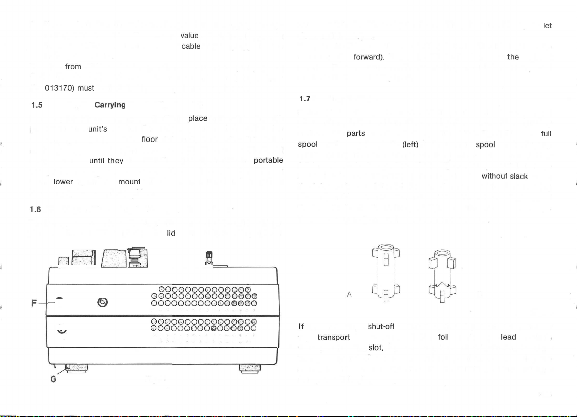
1.6
The transparent cover has a locking button on each side and two hinge
plates at the rear. When placing the
from
50 Hz to 60 Hz Operation, a 60 Hz motor pulley (UHER
013170)
Attaching the
Attaching and Removing the Transparent Dust Cover
Iower
must
be installed by an experienced technician.
Carrying
unit's
until
right rubber
Handle (Figs. 1 and 3)
housing. For upright Operation of the unit, swing
floor
they
are tight. To adjust the handle for
mount
will release it, and the handle may then
value
selected will appear in
cable
may be plugged into a
place
in the threadings (F)
of the unit; the handle will be auto-
portable
lid
on the unit, the hinge plates
must catch in the hinge slot in the machine, then the lid may be
down until it catches.
To open the lid, press the two locking buttons. The lid may then be
swung up (or
opening. To protect the machine from dust, the lid should be placed
on the unit after switching it off.
1.7
Loading the Tape
Before placing the spools on the spindles, pull up the two 3-pronged
pins on the spindles and turn them so that the prongs of the stationary
and movable
spool
on the supply spindle
spindle (right). Then turn the pins to the right or to the left until they
fall in and catch. See position "B" in Fig. 4. The spools will then be
secured and cannot fall off. Next, run a tape lead -
the left spool around the left tape tension sensor, into the threading
slot and, making one or two rotations by hand, wind the beginning of
the tape lead onto the right spool. When loading the tape, the Tape
Transport Switch @ must always be in STOP position.
forward).
parts
It may be lifted off after even
are aligned. See position "A" in Fig. 4. Place the
(left)
and an empty
spool
without
the
on the take-up
slack
let
slightest
füll
- from
nf^fl
_
ooooooooooooooo©
—
©
0
©OOOOQOOOOOOOOOO
^
jj_
ü
I
ooooooooooooo©
OOOOOOOOOOQOOOOO
oooooooooooooooo
oooooooooooooooo
QOOOOOOOOOOOOOO©
oooooooooooooo
Fig. 3
N)
B
Fig.
If
the end-of-tape
tape
transport
the tape threading
Transport Switch ® beyond the START position. On releasing the
switch, it will automatically return to the START position, and tape
transport will begin.
shut-off
switch is activated just after the Start of
because the switching
slot,
tape run may be started by turning the Tape
foil
on the tape
lead
is still in
25
4
Page 28
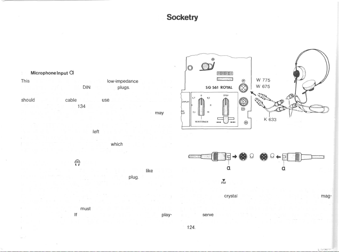
2.
2.1
Microphone
This
input is for direct connection of all
microphones equipped with
ing with two dynamic mono microphones, UHER Adapter Lead K 626
should
be used. For
with mono microphones, K
For mono recordings, UHER Condenser Microphone M 646
connected directly. To connect two mono microphones for Stereo
recording, UHER Adapter Lead K 626 is needed. The yellow marking at
the end of the lead indicates the
channel. To extend the connecting lead, use UHER Extension Lead
K 110 and UHER Adapter Lead K 626, in
will be provided by the microphone's built-in battery.
2.2 Headphones Output ^ (Fig. 5)
This socket is for connecting Stereo headphones that,
W 675 and W 775, are equipped with a 5-pin
headphones with LS-7 plugs, like UHER's W 674 and W 774, requires
the insertion of UHER Adapter K 633.
The headphones socket is equipped with contact Switches for shutting
the built-in loudspeakers of the machine out of Circuit; in which case
the notch of the plug ("a")
points outward (Fig. A).
back will be through the headphones and the loudspeakers simultaneously.
26
Input
Q
Iow-impedance
DIN
connecting
cable
extension:
134
with Stereo microphones.
left
must
be inserted into the socket so that it
If
the plug notch points inward (Fig. B),
plugs.
use
UHER Extension Lead K 110
channel, the red marking the right
which
case the power supply
plug.
dynamic Stereo
For Stereo record-
may
be
like
UHER's
Connection of
play-
Socketry
W 674
W 774
Fig.
5
Fig.
A
2.3 Phono Input M ^ (Fig. 6)
This input socket is for direct connection of Stereo record-players that
have DIN plugs and
netic pickups may also be connected if they have a built-in equalizing
preamplifier. Moreover, by using UHER inter-unit lead K 541, the socket
may also
tape or cassette recorder, a Stereo receiver or UHER mixer MIX 500
A
serve
124.
crystal
pickup cartridges. Record-players with
to connect high-impedance input sources like a Stereo
Fig.
B
mag-
Page 29

2.4 Radio/Phono l
This
socket is for
recorders,
äs
record-players with magnetic pickups if also
preamplifier)
use
the
SG 561 with a tuner'or receiver for record or playback, con-
Input/Output £ (Fig. 6)
connecting
well
äs
stereo
record-players
tuners
or receivers, tape or cassette
with
crystal
if such equipment has Standard
pickup
equipped
DIN
plugs
cartridges
with an
equalizing
or sockets. To
(or
nect this socket to the TAPE socket of the radio equipment via UHER
inter-unit
With
lead
K 541.
older
mono equipment UHER Adapter K 837 will usually have to
be inserted into the socket of the mono set before the inter-unit lead
(K
541)
may be used to
make
connection to the SG
561.
2.5 Remote Control Socket A (Fig. 6)
This socket may be used to connect UHER Manual Remote Control
Switch F 111, UHER Foot-Operated Remote Control Switch
UHER
"Akustomat"
switch that Starts tape
or
speech)
F411.
The
transport
"Akustomat"
in record mode when sound (music
is an automatic
begins and stops tape transport when the sound stops.
F211
or
start/stop
2.7
Left
Loudspeaker Output £ l (Fig. 6)
This socket is for connecting an external, loudspeaker (with an im-
pedance of at
6 watts) for playback of the
playback of the left channel is automatically cut off if the
external Speaker is inserted into this
least 4 ohms
and power handling capacity of at
left
channel. The
built-in
loudspeaker for
plug
socket
äs
shown in Fig. A. By
least
for the
turning the plug 180° (see Fig. B), the left channel of a stereo recording may be heard simultaneously through the built-in and external
Speakers. Headphones with LS-7 plugs may also be connected to this
socket if their impedance is 200 ohms or higher. If the impedance
is
less
than 200 ohms, high volume levels during playback may destroy
headphone cartridges.
Fig.
6
G5-
II«
2.6 Slide Projector Socket Ä £2=
This socket may be used
(Fig. 6)
äs
a monitor Output for connecting the
SG 561 to an amplifier equipped with a monitor input socket. For
amplifiers with cinch sockets use UHER Lead K 562; for amplifiers
with DIN socketry use UHER Connecting Lead K 563 (see also sec.
4.3).
UHER Slide Projector Lead K 911
socket when connecting the SG 561 to an automatic
should
also be connected to this
slide
projector
(to use the SG 561 to trigger slide changing automatically by means
of the UHER "Dia-Pilot" - see also sec. 8).
2.8 Right Loudspeaker Output
4a
II (Fig. 6)
This socket is for connecting an external loudspeaker (with an impedance of at least 4 ohms and power handling capacity of at least
6 watts) for playback, of the right channel. The built-in loudspeaker
for playback of the right channel is automatically cut off when the
plug for the external
Speaker
is inserted into this socket
äs
shown in
Fig. A. By turning the plug 180° (see Fig. B), the right channel of a
stereo recording may be heard simultaneously through the built-in
and external Speakers. Headphones with LS-7 plugs may also be con-
nected to this socket if their impedance is 200 ohms or higher. If the
impedance is less than 200 ohms, high volume levels during playback
may destroy headphone cartridges.
27
Page 30

3. Controls and Their Functions
Encircled numbers refer to
3.1 MICRO Switch ©
Pressing this switch into its locking down-position switches into circuit
the Stereo
cutting
3.2 Separate-Channel Level Controls @ and © for MICRO
Level Control © (upper knöb) regulates the record
channel of a stereo input source connected to
or Radio/Phono l sockets & . The record level will then be registered
on the left level meter@.
Level Control (3)
channel of a stereo input source connected to the MICRO Q or
Radio/Phono l sockets Ä . The record level will be registered on the
right
3.3
Level Control © (upper knob) regulates the record level for the left
channel bf a stereo input source connected to the Phono II
The record level will then be registered on the left level
Level Control © (Iower knob) regulates the record level for the right
channel of a stereo input source connected to the Phono II
The record level will be registered on the right level
microphones
out the input source connected to the Radio/Phono l
and Radio/Phono l Inputs
Itevel
meter®.
Separate-Channel
for Phono II Input
connected to the
(Iower
knob) regulates the record level for the right
Level Controls
Microphone
©and
the
©
fold-out
socket Q while
level
either
the MICRO Q
meter®.
meter©.
Illustration
socket^-
for the
socket^.
socket-J..
of the SG
left
28
561,
found
at the end of the Operating
3.4 Level Meter for Left Channel ©
The left meter © registers the peak level readings for the left channel
of a stereo Signal in both record and playback
3.5 Level Meter for Right Channel ©
The right meter @ registers the peak level readings for the right
channel of a Stereo Signal in both record and playback modes.
3.6 MONITOR (SOURCE/TAPE) Switch ®
This switch is for selecting the mode of monitoring during record:
TAPE (switch in up-position) or SOURCE (switch pressed into down-
position).
tically at once during record, for in TAPE position the Signal just recorded
may
monitoring the Signal delivered by the input source may be heard while
it is being recorded on the tape. This direct comparison of source and
tape recording
3.7 MULTIPLAY/ECHO Control ®
In
trol
ferred
gramme will be also recorded on track 2, the record level of which
must be adjusted by means of the appropriate level control for the
input source from which the new programme is being recorded.
It
allows the quality of the recording to be
be monitored directly off the tape. On the other hand, with SOURCE
lets
differences
"multiplay"
is used to regulate the record level of the programme to be trans-
or
sound-with-sound
from
track 1 to track 2. At the same
between the two be easily recognized.
Instructions.
modes.
checked
Operation (see sec. 7.4) this con-
time
an additional Pro-
acous-
Page 31
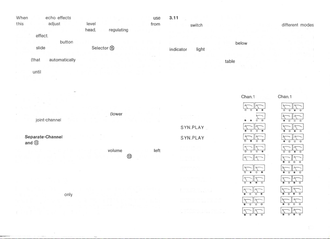
When
adding
echo
effects
during mono recording (see sec. 7.1),
this
control to
the playback head to the record
the echo
Pressing the control
to trigger
or STEREO position and the SG 561 is set in record mode. The trigger
pulses
matic slide projector during subsequent playback) should not be recorded
corded (see sec. 8).
adjust
the record
effect.
button
slide
changing if the Mode
(that
will
automatically
until
the sound track for the slide show has already been re-
level
of the Programme going
head,
thus
regulating
® will record a pulse on the control track
Selector©
control the changing of slides in an auto-
the strength of
is in either DIA-PILOT
use
from
3.11
Operating Mode Selector ©
With this
of Operation. The corresponding track in use and the record or playback funtion to which the machine is set are shown by four illuminated
function indicators located just
indicator
made. The function indicator Signals playback on its track by lighting
up green. In the following
in each case are shown by the filled-in circles.
switch
the SG 561 may be set for eleven
below
will
light
up red to signal that on its track a recording is being
table
the function indicators which light up
different
the level meters. The function
modes
3.8 Dual Control for Treble ® and
Bass © Adjustment
Control ® (upper knob) is for adjusting treble response of both
channels jointly during playback. Control ©
used for
The upper knob © regulates the playback
channel of a Stereo recording. The Iower control © regulates the
volume of the right channel.
Pressing this switch sets the machine into record mode. The button
will remain depressed
from STOP position to either the PAUSE or START position. When the
Tape Transport or Fast-Wind Switch is in PAUSE and START, the Record
joint-channel
3.9
Separate-Channel
and®
3.10 RECORD Button ®
Button is locked and cannot be depressed.
adjustment of bass response during playback.
Volume Controls ®
only
if the Tape Transport Switch ® is moved
(Iower
volume
knob) should be
level for the
left
ECHO 1
SYN.PLAY 2
SYN.PLAY
MONO 2
MONO 1
STEREO
MULTIPLAY 1
MULTIPLAY 2
MONO/DIA-PILOT
STEREO/DIA-PILOT
1
Record Playback
Chan.1
Chan.2
Chan.1
BE
0*00
o • o o
Chan.2
29
Page 32

Track location is clearly shown in the illustrations
below.
The numbers
indicate the track, the arrows the direction of tape movement. Ex-
changing the
füll
take-up
spool
with the empty supply
spool
prepares
for playback of the corresponding second track. For example, with the
Mode Selector in MONO 1 Position: track 2 will be set up for playback
in
dual-track
Operation, track 4 in
quarter-track
Operation. In
dual-track
Stereo Operation the machine is automatically switched to rewind at
the end of the tape; in quarter-track Stereo Operation the
empty tape spools
must
be changed over
manually.
füll
and
3.12 Tape Speed Selector ®
Turning this Switch selects one of the machine's four tape speeds and
simultaneously Switches on the power supply
(which
is off when this
switch is in "0" position). With the Switch in AMPLIFIER position the
drive
motor
may
is switched off, so
be used
äs
a mono or Stereo
that
the amplifier section of the SG 561
hi-fi
amplifier (see also s'ec. 10).
3.13 Tape Transport Switch ®
Turning this switch selects the tape
or START.
It
can be turned
only
transport
when the
functions STOP, PAUSE
Fast-Wind
Switch ® is
locked in its neutral mid-position.
Turning the switch beyond the START position disengages the auto-
matic
end-of-tape
threading
<äver
tape
slot
speed
shut-off
will be
has
switch. Thus switching
transported
been
and wound onto the spool at
selected.
foil
in the tape
what-
30
Illllllllllllllllllllllllll
Mono + Stereo
~2"
DIA t
Morto
DIA
t Stereo
l l L
3.14 Fast-Wind Switch
i
for Fast-Forward
and Rewind
This
slide
control
locks
in its mid-position
left
end-positions and Switches the machine to the fast-wind functions
Fast-Forward
^-
>•
or Rewind
-^-^.
äs
well
äs
in its
right
The switch can be operated only
when the Tape Transport switch ® is in STOP position.
3.15
Counter
Pressing the zero reset key cancels any given
the counter reading to "0000".
to press the reset key or to note the starting
with Reset Key ®
Index
number, returning
Betöre
each recording it is advisable
Index
number for fast loca-
tion of recorded passages upon subsequent playback.
and
Page 33

4. Connecting the SG 561 to the Amplifier of a Hi-Fi Sound System
The following examples represent the most frequently used types of equipment and the connections they require for incorporating the SG 561 into a
high-fidelity
the correct connections.
sound System. With the additional technical remarks in sec. 12, the technician will be able to select any other arrangement and also make
4.1 Connecting to an Amplifier with
Fig. 7 illustrates how to connect the SG 561 to a
equipped with a 5-pin DIN combination input/output socket for record
and playback. All other amplifier input sources (e.g., tuner or recordplayer)
should
be connected to the corresponding input sockets of the
amplifier. The amplifier connection to the SG 561 should be to the
•4
socket via UHER Stereo Lead K 541 and will permit recording from
any of the equipment connected to (and fed through) the amplifier of
the audio System. The MICRO switch © should remain in up-position.
Although
advisable to connect
SG
when recording from microphones.
microphones
561;
in which case the MICRO Switch © should be pressed
may
them
directly to the
DIN
Sockets
hi-fi
amputier
also be connected to the amplifier, it is
Microphone
socket Q of the
only
Experience has shown that it is best to monitor microphone recording
with the MONITOR Switch ® in TAPE position.
4.2 Connecting to an Amplifier Not Equipped with
DIN Sockets
Fig. 8 illustrates how to connect the SG 561 to an amplifier that is
not equipped with DIN sockets. In
equipment
the corresponding input sockets of the amplifier. For record Operation,
the tape Output socket of the amplifier should be connected to the
Phonoll
back, on the other
(e.g.,
tuner or record-player) should also be connected to
socket^
of the SG 561 via
hand,
this
connect the
case all other amplifier input
UHER
Lead K 551.
Radio/Phono
For
play-
l socket A of
Fig.
7
Page 34

the SG 561 to the tape
second K 551
the
left
Switch ©
lead.
stereo channel, the red marking the right channel. The MICRO
should
not be pressed except when recording
input
socket of the amplifier by
The yellow marking at the end of the
means
of a
lead
indicates
from a micro-
phone connected to the Microphone socket Q of the tape machine.
4.3 Connecting to an Amplifier Equipped
with Monitor Input
Fig. 9 illustrates the connection to a
high-fidelity
amplifier that is
equipped with monitor input connecting facilities and a switch for
selecting
from-source
connect the tape Output of the
or off-tape monitoring. For record Operation,
amolifier
to the
Phono
II socket
-J
of the SG 561 via UHER lead K 551 (if the amplifier has einen socketry)
or K 541 (for
For playback, connect the MONITOR socket of the amplifier to the
DIN
5-pin sockets).
K>
<Z2^
socket of the SG 561, using UHER Monitoring Lead K 562 (if the
amplifier has cinch socketry) or K 563 (for DIN sockets). The yellow
marking at the end of the lead indicates the left channel, the red
marking the right channel. Through
this
connection and with the monitor switch of the amplifier in the appropriate Position (see öperating
instructions
source or off-tape
making it
for the amplifier), the recording
through
unnecessary
the loudspeakers of the sound System, thus
to correct stereo headphones for monitoring
may
be monitored from-
purposes.
Fig.
32
4.4 Connecting to a Receiver, a
Single-Unit
Console or Tuner
Make connections
Lead K
541.
ceiver, console or tuner. For microphone recording, the
äs
described in sec. 4.1 above, using UHER Stereo
A record-player should be connected directly to the re-
microphones
should be connected to the Microphone socket Q of the SG 561 and
the MICRO Switch (T) pressed into down-position.
When recording from radio or record-player, monitoring may be from
source or off-tape
äs
described in sec. 4.3. It is best to monitor microphone recording through stereo headphones, whether monitoring is
from-source or off-tape.
9
Page 35

5. Record Operation
As the quality of a recording depends largely upon correct setting of the record level, especial attention should be given to the process of level
adjustment (see also sec. 5.23).
5.1
For
Users in a
Proceed
äs
1. Connect the desired input source to the appropriate socket and
switch
connected, but they should be switched off. (Using the
Switch
2.
Make
certain
outlet
3.
Switctt
ing on the power supply.
4. Load tape
to the operating
5. Press Record Button ® and hold down
Transport Switch ® to PAUSE position.
6. Press Counter Reset Key ® or note index number so that the recording may be accurately marked for
7. Using the appropriate Level Controls @ and © or @ and
adjust record level so that the record level meters © and © read
exactly 0 dB at the
Hurry
follows:
the input equipment on. All other input
©,
cut
microphone
that the SG 561
(A.C.).
machine to desired tape speed,
äs
described
mode
input in or out of circuit,
\s
connected to the
thus
in sec.
1.7
above and set Mode Selector ©
to be used in recording.
while
later
cataloguing.
loudest
Programme passages to be recorded.
sources
simultaneously switch-
may
remain
Microphone
äs
appropriate.)
mains
power
setting the Tape
© ,
8. Set the Tape Transport Switch ® to START, and recording will begin.
9. Recording may be interrupted by switching from START to PAUSE,
but the machine will remain in record mode.
10. After recording one complete run of the tape, exchange the
right spool with the empty left spool and continue recording,
cribed above, on the second track(s). (In
rewind tape,
11.
When recording from microphones, it is
headphones
MONITOR Switch in TAPE position. In that way the possibility of
acoustic feedback between microphones and Speakers (recognizable
by the
secondly, disturbing background noises may be detected immediately
and perhaps be avoided by altering microphone placement while
recording.
12.
Upon completing the recording, the tape speed, recording mode
and Programme selections should be noted on the tape
the tape spool and on the tape storage box.
then
continue recording on
(rather than through the loudspeakers) with the
howl
and whistling noises produced) will be prevented, and
dual-track
another
advisable
tape.)
to monitor
füll
äs
des-
stereo Operation:
through
lead,
on
33
Page 36

5.2 For
5.21 Connecting
Sound
2.3 and 2.4, also giving consideration to the remarks found in sec. 4.
All of the
only
controls for maximum record level of an input source connected to the
RADIO/PHONO
and ©
check contact pin arrangement and input impedances to ascertain
whether better recording conditions might be
the input source to the PHONO II socket ^ by
adapter
audio
kept at the top of the scale for an input source connected to the
PHONO II socket ^ , the crossover adapter may be used to connect
the input equipment to the RADIO/PHONO l socket ^ .
Consult your audio dealer if you are unable to find the proper arrange-
ment by yourself.
5.22
When connecting the SG 561 for the first
should be given to the remarks found in sec. 1.4 above. Never forget to
unplug the machine from the
True
Audio
Enthusiasts
Input
Sources
source
equipment
input
sources
the source to be recorded should be
l socket
must
always be kept just
(change
shops.
Power
pin 1
Conversely, if Level Controls © and © must always be
Supply
should be connected
may remain connected during recording, but
4s
, it is found that Record Level Controls ©
hardly
open in the Iowest
with
pin 3, pin 4 with pin 5) obtainable at all
mains
outlet before changing the fuse or
äs
described in secs.
switched
achieved
means
time,
particular attention
on.
If,
when setting
scale
by connecting
of a crossover
2.1,
ränge,
34
the voltage setting. The
outlet before cleaning the housing with a moistened
is properly loaded and the machine
setting, the
5.23 Making Record Level Test and Starting to Record
Making
the record level without tape movement before starting to record. Once
the tape has been loaded
pared for by pressing the Record Button ® and moving the Tape
Transport Switch ® from STOP to PAUSE.
Once these preliminaries have been completed, use Level Controls
and © (for input sources connected to the RADIO/PHONO l input
or Level Controls @ and © (for input sources connected to the
PHONO II input
Meter © or @ to register 0 dB at the loudest Programme passages
to be recorded.
Particular care should be taken in making
the record level too high (overloading - the pointer moves into the
red band)
Playback
always stays considerably
strong hiss during playback.
Turning the Tape Transport Switch from PAUSE to START sets tape
transport
lamps
a record level test should be understood to
leads
to
while
setting the levels too
in motion and permits actual recording to begin.
plug
should also be removed from the mains
cloth.
When tape
has
been switched to a tape speed
in the Record Level Meters should
äs
described in sec. 1.7, the test can be pre-
3i
) to bring the pointer of the corresponding Level
this
distorted
recordings and hence to
Iow
(under-recording - the pointer
below
the 0 dB mark) will be reflected by
light
up.
mean
adjusting
regulation, for setting
shrill
and
distorted
©
4;
)
Page 37

6. Playback Operation
6.1 For Users
Playback may be directly
listening through
may be switched in or out of circuit,
external loudspeakers are connected, the built-in Speakers may also
be switched in or out of circuit
Playback Procedure:
1. Load tape
tor ® to the speed of the recording.
2. Set Mode Selector ® to
3. Set Tape Transport Switch ® in START position.
4. For playback through the power stage of the SG 561, adjust the
volume of the two channels to desired
and ® ; then adjust treble
Control © . When playback is to be through the Speakers of an
audio System, all of these adjustments should be
amplifier controls of the System itself.
in a Hurry
through
headphones,
äs
described in sec. 1.7 and turn Tape Speed
the
machine's
the
built-in
äs
äs
desired (see secs. 2.5 and 2.6).
mode
of recording (see sec.
with
Control ® and bass response
amplifier stage.
loudspeakers
desired (see sec. 2.2). When
level
by means of Controls ®
When
of the SG 561
Selec-
5.1,
point
12).
with
made
with the
5. After playing one run ot the tape, exchange the
right spindle with the empty one on the
more and continue playback
6.2
ForTrue
Playback quality depends chiefly
Neither the world's best amplifier nor the world's best loudspeakers can
correct wrong record level settings. In Stereo Operation, at
built-in loudspeakers serve
better monitoring of a stereo recording is possible
phones are used.
the tape head should be cleaned (see sec.
In stationary Operation, playback will be through loudspeakers connected either to the
to the amplifier of a hi-fi audio System. In case of the latter, give careful
attention to the remarks made in sec. 4
the Amplifier of a Hi-Fi Sound System". All
the SG 561 for playback should be accomplished in the Order des-
cribed in sec. 6.1 above.
Audio Enthusiasts
Very
weak playback of high frequencies suggests that
10-watt
äs
described above.
upon
only
monitoring purposes; yet considerably
(per channel) power stage of the SG 561 or
left;
the quality of the recording.
11).
"Connecting
other
füll
spool
on the
thread
the tape once
least,
when
Stereo head-
the SG 561 to
Steps for setting up
the
35
Page 38

7. Special
Effects
and Trick Recording
The following recording functions
7.1 Mono Recording with Echo Effects
Reverb and echo
changing the tape speed, it is possible to go
truly
effective
Recommended tape speeds for the following effects:
19
cm/s reverb effect
9.5cm/s echo
4.7cm/s
2.4
cm/s echo trick effect
Procedure
1.
Select appropriate tape speed for desired effect.
2. Connect
recording from microphone(s), press MICRO Switch
3. Depending on the track to be
Mode Selector ® to ECHO 1 (to record on track 1 or track 4) or
to
ECHO
eration the Mode Selector ©
4. Use Level Control MICRO/RADIO @ to adjust to proper record
level
(äs
to
regulate
5. For best monitoring of echo recordings use UHER Headphones
W 775, inserting the
built-in
MONITOR pushbutton switch should be in TAPE position.
6. Playback Operation is the
Selector©
of the echo recording.
36
effects
can also be
echo trick recording.
echo with greater reverberation
for echo recording:
input
source
äs
described in secs. 2.1, 2.3 or 2.4. When
2 (to record on track 2 or track 3). During dual-track Op-
described in sec. 5) and the MULTIPLAY/ECHO Control ®
the
strength
Speakers of the SG 561 are
may either be in ECHO position or be set to the track
of the effect (reverb or echo).
plug
into the Headphones socket so that the
same
produced
used
should
always be in ECHO 1 position.
switched
äs
for normal recordings. The Mode
with the SG 561. By
from
time
for the recording, set the
off (see sec. 2.2). The
may
the reverb
©.
be accomplished in both
effect
to
dual-track
7.2 Stereo Recording with Echo Effects
Echo recording in the stero
UHER Monitoring Lead K 563.
Procedure:
1. Set Mode
2. Switch the tape machine to the record function.
3. Connect Monitor Lead K 563 from
to
;J
socket (5-pin plug).
4. Feed in the input signal to
either
through
down-position) through the Q socket and adjust the record level
with MICRO/RADIO controls (2) and © . The MONITOR
must
remain in up-position. To regulate the strength of the echo
Signal, use PHONO controls © and © .
5.
If
the ^ socket is used to record the original Signal, the monitoring
lead
(K 563) may then be connected to the
case the PHONO controls © and (5) should be used to regulate
the record level of the original signal and the MICRO/RADIO controls @ and (D for the strength of the echo signal.
7.3
Sound-on-Sound
In sound-on-sound recording one track is played
a recording is being made on the corresponding parallel track. An array
of trick effects may be achieved with this technique. For example, one
can sing a duet
nique works.
and
Selector®
the
("Synchro-Play")
with
oneself. Fig. 10
quarter-track
mode
in STEREO Position.
,5
socket or (with the MICRO Switch © in
Operation.
is best accomplished with the aid of
£,
CJS
socket (6-pin plug)
which
the echo effect is to be added
£.
socket, in which
while
simultaneously
shows
graphically
how the tech-
.Switch
Page 39

Fig.
10
The
sound-on-sound
slide
and film shows. The well
technique
is
particularly
thought-out
useful
design and
in making
construction
home
of
the SG 561 make it most easy to produce trick recordings.
Procedure:
1.
Turn Mode Selector © to SYN.PLAY 1 position.
2. Set MONITOR Switch in SOURCE position. Both knobs of the
sepa,rate-channel
the way to the
3. Connect microphone to Q socket and press the MICRO Switch
4. Connect
Volume Controls © and ® should be turned all
left.
headphones,
like
UHER
Midget Magnetic
Earphones
©.
W 214
or UHER Stereo Headphones W 674 or W 774, to the socket p l
(the
plugs
of the Stereo headphones should be plugged together
before making the connection.
5. As previously described, make a first recording from the microphone.
Adjust the record
level
with
the upper knob of the MICRO/RADIO
control @ . The left Level Meter © will go into action.
6. Rewind tape to beginning of first recording.
7. Turn Mode Selector © to SYN.PLAY 2 position.
8. Put on headphones.
9. Press Record Button © and Start recording.
While
listening to the
playback of the first recording through the headphones (playback
volume
may
be adjusted with the upper knob of VOLUME Con-
trol®),
make a second recording synchronized to the first one.
Use the upper knob of the MICRO/RADIO Control @ to set the
record level
which,
in turn, will be indicated by the right Level
Meter ©.
10. On completing the recording, rewind the tape and disconnect the
headphones.
11.
For playback of a sound-on-sound recording, turn the Mode Selector
® to STEREO position, set the MONITOR Switch in TAPE position
and Start tape
7.4
Sound-with-Sound
The sound-with-sound technique
mono trick recordings by transferring one recorded track to
while
simultaneously adding a new recording. Repeating the process
several
times
with-sound recording the two tracks needed (in
transport.
("Multiplay")
makes
it possible to produce multiple
another
may result in a one-man sextet, for instance. For sound-
dual-track
Operation:
track 1 and 2; in quarter-track Operation: tracks 1 and 3 or 2 and 4)
must
be initially unrecorded or erased. Fig. 11 illustrates graphically
the distribution of tracks in this type of Operation. The
well-designed
construction of the SG 561 makes this type of recording simple and
effortless.
37
Page 40

Procedure:
1. Turn Mode Selector (B) to MULTIPLAY 1 position.
phone to Q socket (connecting a Stereo
makes
only
the
microphone System for
the
MICRO Switch
turn the Tape Transport Switch ®
During tape movement the MONITOR Switch ® should be in TAPE
Position, and it should be in SOURCE position when tape is not in
motion.
2. Using UHER Adapter Lead K 633, so connect a
UHER W 674 or W 774) to each of the sockets
the
^l
socket that the
secs. 2.2, 2.7 and 2.8), first plugging the red
into the yellow plug. The headphone connected to the O II socket or to
the K 633 adapter (yellow connector) is for
cording
engineer";
K 633 adapter (red connector) is for monitoring by the
avoid the possibility of having the headphones destroyed during
back at high volume levels, only headphones with an impedance of
200
ohms
or more should be connected to the
3. Turn MULTIPLAY/ECHO Control © all the way to the
4. After selecting the tape speed (19 cm/s and 9.5 cm/s are best
suited to sound-with-sound recording), set the record
means of the upper knob @ of the MICRO/RADIO Control, making
certain that the MONITOR Switch is in SOURCE position. Next
switch to TAPE monitoring; then begin tape movement by turning
the Tape Transport Switch from PAUSE to START. Recording will
commence on track 1.
5. When recording on track 1 is completed, rewind the tape to the
beginning of the recording Programme. Then switch the Mode
Selector ® to MULTIPLAY 2. The artist should put on his headphones. Next, press the Record Button @ and then Start tape
transport
recording through his headphones (the volume
with the upper knob ® of the VOLUME Control) and can thus
for the second recording. The artist will
©.
While
holding the Record Button ® down,
built-in
loudspeakers are switched off (see
the headphone connected to the
microphone
channel
from
STOP to PAUSE position.
Connect
automatically
1 active), and press
headphone
<l
l and
tl
II or to
plug
of the headphone
monitoring
43
<ll
socket
l and
(all
left.
hear
may
be regulated
by the
"artist".
sockets.
level
the first
micro-
(e.g.,
"re-
orthe
To
play-
by
38
make
the second recording in synchronism. The recording engineer
will hear both recordings if the machine is in TAPE monitoring position, and he may regulate the record level of the new recording
with Level Control @ and that of the recorded track being transferred by means of the MULTIPLAY/ECHO Control
relative volume of both recordings may be adjusted whenever
desired.
6. To add still another recording: rewind the tape, switch the Mode
Selector® to MULTIPLAY 1 and repeat the record Operation
already described. If yet another recording is to be added, turn
the Mode Selector © to MULTIPLAY 2, rewind the tape and continue the alteration
desired is completed.
7. For subsequent playback of a sound-with-sound recording, set the
Mode Selector © in MONO 1 position if the switch was in MULTIPLAY 1 position when the recording was completed. If at the end
of the recording the Mode Selector was in MULTIPLAY 2 position,
switch it to MONO 2. From this point, playback Operation is the
same
äs
for normal recordings.
If sound-with-sound recording in Stereo is desired, a second tape recorder and a mixing console
The recording procedure is described in the operating instructions of
the
mixer.
until
the multiple sound-with-sound recording
(like
UHER MIX 500 A
®.
124)
will be needed.
Hence the
äs
Fig.
11
Page 41

8. "Dia-Pilot"
Coupled with an
produce a
only
will provide the running commentary together with background
rnusic
and sound
projector. The "Dia-Pilot" operates at all tape speeds except 2.4 cm/s
and requires no
Procedure:
1. Set up the SG 561 and the projector (together with its remote
control
2. Depending upon
Stereo (Stereo dubbing is possible only
quarter-track Operation), switch the Mode Selector ® to MONO 1
or STEREO. Operation of the tape machine for actual sound re-
cording is the
above.
A record-player or another tape recorder may be connected to
the
KI
effects using the PHONO Level Controls © and
To make the slide show particularly impressive, first write a brief
production schedule to be followed in recording text and sound.
Speaking the commentary into the
RADIO Control © (or @ and
use the PHONO Level Control
musical background and/or sound effects. With the projector's
remote control lead, Signal slide change manually so that the picture that appears will always correspond to the recording.
3. Once the recording of the sound track has been completed, rewind
the tape and return the slide magazine of the projector to its beginning position. Also disconnect the remote control lead
automatic
fully
automatic slide Show with sound, for the SG 561 not
effects,
further
lead)
for Operation.
socket. Thus it is also possible to fade in
slide
projector,
but will also control the slide changing of the
accessory
whether
same
equipment.
the sound dubbing is to be in mono or
äs
described in sec. 5
@)
the
SG 561
when
microphone,
to set the correct record
©(or
© and
may
the SG 561 is in
"Record
music
©.
use the
©)
to fade in the
be used to
Operation"
or sound
MICRO/
level;
from
the
procector. Next, disconnect all input sources from the SG
then connect the remote control socket of the projectorto the ^ c3"~
socket of the SG 561 via UHER Lead K
4. If the sound track has been recording in mono
quarter-track), set the Mode
Start tape motion for record once more. If the sound track is in Stereo,
switch the Mode Selector © to DIA-PILOT STEREO. Playback of
the sound track will then be heard. Whenever the slide should be
changed, press the MULTIPLAY/ECHO Button @ . The projector will
change the slide. At the same time a control pulse will be recorded
on track 4, that will trigger the projector to change the slide automatically on subsequent playback.
5. When all of the slides have been run through, rewind the tape and
return the slide magazine to its
SG 561 can automatically take over the presentation of the slide
show. Turn the Mode Selector © to DIA-PILOT MONO or DIA-PILOT
STEREO; Start tape
volume on your amplifier. The tone may also be regulated with the
TREBLE and BASS Controls ® and © of the SG
One more tip:
If you should happen to record a control pulse at the wrong
if you should wish to add another slide to the series
need to do is to run the tape through once more
and 4 above) and press the MULTIPLAY/ECHO Button ® at each point
at which you wish a change of slides to be triggered. All of the previously recorded control pulses will be automatically erased and replaced
by the new ones.
Selector©
transport
911.
(dual-track
to DIA-PILOT MONO and
starting
point once more. Now the
for playback and adjust tone and
561.
later
(äs
described in Steps 3
561;
or
place
or
on, all you
39
Page 42

9.
Connecting
Accessory
Equipment and Adjusting the
SG 561 to Special Operating
9.1 Operation with UHER
The "Akustomat"
SG 561 is set for Operation in the MONO 1 position, the Akustomat
F 411 will automatically Start and stop tape
and end of recording.
For
further
Akustomat F
9.2
Operation with UHER Timer A 403
The power supply of the SG 561
A 403. For playback, turn the Mode Selector © and the Tape Speed
Selector © to the desired position, then the Tape Transport Switch ®
to
START.
If
the timer is to regulate a recording, the input source to be recorded
must
also be connected to the timer, and the SG 561 must be set in
record mode (i.e., the RECORD Button @ must be locked in downposition).
9.3 Recording with UHER Telephone Adapter A 261
UHER's galvanic Telephone Adapter A 261 should be connected to
the
£>
socket of the SG 561. In
connected to the telephone by the telephone authorities or
phone Company.
For recording, the Mode Selector © must be in MONO 1 position;
otherwise
It is advisable to use a
which the record level may be adjusted with the MICRO/RADIO Con-
trol
©.
40
F411
particulars,
411.
the procedure is
"Akustomat" F 411
is an electronic-acoustic switch. When the
transport
It
should
be connected to the socket marked A.
see the operating instructions
may
be switched on by UHER Timer
most
countries the adapter must be
äs
described in sec. 5 "Record Operation".
"lest"
call
to
make
a record
at the beginning
supplied
level
with the
local
test during
tele-
Conditions
9.4 Changing UHER Tape Head Assembly Z 345 or Z 346
(Fig.
12)
1.
Pull front cover cap (A) up and off.
2. Loosen the two knurled nuts (B) by rotating to
3. Pull tape
4. Push the replacing tape head mount down into
it with the knurled nuts and replace the front cover cap.
9.5 Azimuth Adjustment of Playback Head (Fig.
In hole (D) of the tape head mount there is an adjusting screw with
which the playback head may be tilted
head
mount (C) straight up and off.
(within
left,
and remove.
place;
then secure
12)
limits) to the left or right
Fig.
12
Page 43

of its normal perpendicular position so the SG 561 may also
recorded on machines with non-standard record head positions.
Adjustment should be made (with an anti-magnetic screwdriver)
hearing
the best reproduction of high frequencies. To this end, turn the
upper knob of Control ® up all the way for
frequencies.
In restoring the head gap to correspond with the record head of the
SG 561, correct adjustment will have been
reproduction of high frequencies is heard during
of an SG 561 recording. It is best to make this re-adjustment at the
19
cm/s tape speed.
9.6 Using UHER Reducer-Adapter K 853
The K 853 reducer-adapter is for use in connecting the SG 561 to mono
sound equipment. It will always be needed when the mono equipment
has a Standard 3-pin socket that cannot be connected directly to the
SG 561 by
9.8 Erasing
Whenever the SG 561 is operating in record
cording on the tape is
chine should be operated just
© , © and © turned all the way to the
9.7 Adding Sound to Film
The SG 561 also provides a facility for
of sound to 8 mm or
built
pins
record and playback of the sync cueing Signals.
9.9 Rapid Erasure
In special cases it may be desirable to erase a recording rapidly. The
rapid erasure device is provided for this purpose. All that is necessary
is to depress the "Recording" key ® during the Fast Forward or Rewind
Operation. The recording will then be erased by a high pitch whistle tone.
means
of UHER 5-pin Stereo lead K 541.
Only
automatically
16
mm film (two-ribbon technique). The tape head
into the SG 561 for
4 and 6 (6 =
ground)
äs
for record
slide
projector Operation is connected to
of the A «Stocket
füll
playback of the high
achieved
off-the-tape
mode,
erased. For erasure
but
with Level Controls
left.
pulse-controlled
and may be
play
tapes
until
when optimum
monitoring
any previous re-
only
the ma-
@,
synchronization
used
for
10.
Using the SG 561
äs
a
Hi-Fi Stereo Amplifier
With
the Tape Speed Selector ® in AMPLIFIER position, the motors
of the SG 561 remain switched off so that the amplifier stage
Stereo
inputs
may
.
äs
be operated
should
well
microphone
from
Stereo inputs. Either two Stereo record-players
preamplifier) or two Stereo cassette or
be oonnected to the SG 561 via the sockets
PHONO II
After the desired input
trols
Meters © and © will read 0 dB at the
The level
after the other. Next, regulate the treble, bass and
trols
Position. The first input source may then be faded out and the second
source faded in
© and © . To permit making an announcement
phone in addition, the
with the MICRO Switch © during playback of an input source connected
to the PHONO II socket ^ • Use Control (2) to fade in a mono micro-
phone, Controls @ and © for a stereo microphone.
mark the position of the level controls for each input source. Making:
announcements through the microphone may
(noticeable by a whistle or
the live microphone
either set the level controls so high that no whistle is heard or increase
the distance between the microphone and the loudspeakers.
4,
@,
(D , ® and © to adjust the record
adjustment
®, ®, ® and ® and with the MONITOR Switch ® in SOURCE
alone
äs
an amplifier with two mixable
(equipped
open-spool
sources
have been connected, use Level Con-
loudest
be
made
separately for each input, one
äs
regulated by Level Controls @ and © or
input may always be switched in-circuit
howl).
It is caused when the sound entering
the loudspeakers is too strong. In such event,
tape recorders may
RADIO/PHONO l 4;
level
so that the Level
Programme passages.
volume
through
It
lead
to acoustic feedback
with
its
with
equalizing
and
with con-
the micro-
is advisable to
41
Page 44
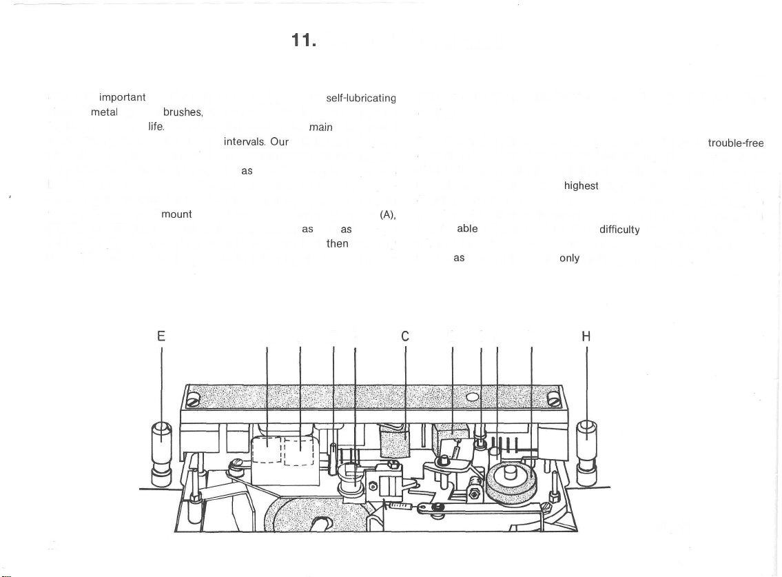
11.
Care and Maintenance
Since all
sintered
ing its entire Service
to checking and cleaning at regulär
should be consulted for this task. The cleaning of tape-touching parts
(that from time to time may be needed,
in playback response, especially of high frequencies) can easily be performed by the user himself. For this purpose, first pull the cover cap in
front of the tape head
(B), (C) and (D), the tape guides (E), (F), (G), (H),
guide roller (l), pressure roiler (K) and the capstan (L) will
accessible and may be cleaned with the cleaning fluids contained in
important
metal
bearing
bearing points are equipped with
brushes,
life.
mount
the SG 561 will not require oiling dur-
Care and maintenance in the
intervals.
äs
may be recognized by a loss
up and off. The magnetic tape heads
main
Our
UHER Service agents
äs
self-lubricating
are restricted
well
äs
the tape
then
be easily
(A),
A B F l
UHER Special Cleaning Kit Z 172 to remove deposits of dust and tape
coating.
The SG 561 is a highly developed precision machine; its
Operation depends upon the exact co-functioning of its mechanical and
electrical components. In designing these important parts, attention
was given to obtaining the
Should malfunctions appear at any time, we recommend Consulting an
experienced audio technician, for experience has shown that he will
best be
able
to spot and correct the
minor nature). We warn strongly against any tampering by non-tech-
nicians
äs
it generally results
highest
degree of operational reliability.
difficulty
only
in still greater damage.
(that will usually be of a
trouble-free
D G L K
42
Fig.
13
Page 45

12.
Additional Technical Remarks
12.1
Contact
Should
impedance of the input source, the input impedance of the playback
machine
in order to avoid
both record and playback.
1. MICRO Socket
Input Signals at pins 3/2 and 5/2 (2 = ground)
and 70 mV. In addition to all
UHER Electret Condenser
to this socket. The power supply for the condenser microphone is provided by the microphone's
supplied with the microphone).
2. Headphones Socket
Maximum
= ground) is 4 V at each; Output impedance is approximately 200 ohms
at each.
3.
Radio/Phono
Input Signals at pins 1/2 and 4/2 (2 = ground) may be between 1.5 mV
and
110
of
more
5/2 (2 = ground) of the Radio/Phono l input, using a crossover
Wiring,
Input/Output
Input/Output
it be necessary to extend
äs
Output Signal delivered to the two pins 4/2 and 5/3
mV. Input impedance is 15
than 70 mV, it is advisable to feed the Signals to pins 3/2 and
well
Voltages
äs
the
lead
loss
of response in the high frequency ränge during
Q
Microphone
built-in
^
l Socket
£,
Impedances,
UHER
Stereo Lead K 541,
capacity must be taken into consideration
may
be between
Iow-impedance
M 645 may also be connected
battery (see the instructions for use
kohms
dynamic
at each. For input Signals
the
Output
0.12
microphones,
(2
and 3
mV
plug.
Input Signals at these pins may be between 40 mV and 2.8 V; input
impedance is
it is advisable to use the Phono II input socket
In playback, Output Signals delivered to pins 3/2 and 5/2 (2 = ground)
of the Radio/Phono l socket are approximately 600 mV at each, out-
put impedance being
4. Phono II Socket
Input Signals at pins 3/2 and 5/2 of this socket may be between 200 mV
and
18V.
5. Remote Control Socket A
Via pins 4 and 3 (3 = ground), the SG 561 may be switched to PAUSE
with either UHER Manual Remote Control Switch F
ated Remote Control Switch F
An output voltage of 26 V (output impedance 390 ohms) is delivered
to pin 1 for Operation of UHER
Signal of the
6.
Slide
The monitor Output of the left channel is at pin 1 of this socket, that
of the right channel at pin 5 (output voltage approximately 600
Output impedance approximately 15 kohms at each). The "Dia-Pilot"
head is run out to pins 4 and 6 (6 = ground) for recording control
pulses in film dubbing. Slide changing for the
via pins 2 and 3.
1.2
megohms at each. For input Signals of more than 1.5 V,
£.
.
15
kohms at each.
^
Input impedance is 50 kohms at each.
111
21
1.
"Akustomat"
left
channel is run to pin 2, that of the right channel to pin 5.
Projector Socket
F411.
The
slide
projector is triggered
or Foot-Oper-
Iow-frequency
mV/
43
Page 46

12.2
Performance Specifications and Special Features
Track System:
Tape Speeds:
Frequency Response:
Max.
Spool
Size:
Wow and Flutter:
(DIN
45507)
Signal-to-Noise
(DIN
45
500)
Ratio:
Crosstalk:
Generator Frequency:
Dual-track
(interchangeable
or quarter-track
tape
head
assemblies
for mono and Stereo record/playback)
19
cm/s
(7
1/2
ips)
9.5
cm/s
(3 3/4
4.7
cm/s
(1 7/8
2.4
cm/s (15/16 ips)
ips)
ips)
20-20,000 Hz
20-15,000 Hz
20- 9,000 Hz
18
cm
(7")
19 cm/s: Less
9.5
cm/s: Less than
than
0.05 %
0.10
°/o
4.7 cm/s: Less than 0.20 °/o
Dual-Track Quarter-Track
Better than
19
cm/s:
9.5
4.7
cm/s:
cm/s:
67
66
65
dB
dB
dB
65
64
61 dB
Better than 60 dB (mono)
Better than 45 dB (Stereo)
Approximately
100
kHz
dB
dB
Erasure:
Inputs:
Outputs:
Level Control:
Monitoring:
End-of-Tape
Shut-Off:
Record/Playback Track
Indication:
Power Output:
Power Supply:
Dimensions: (W X H X D)
Weight:
Playback Level Indication:
19 cm/s: Better than 72 dB
Mic Q 0.12mV-70mV/2kohms
Radio £ (stereo measurement)
1.5mV-110mV/15kohms
Phono l j|.
Phono
Headphones
Monitor
Line £ :
2
level
From-source or
headphones
40
mV-2.8
V/1.2
II ^ 200
^>
^<i?ä=:
mV-18
V/50
4 V/200
approx. 600
approx. 600
meters with dB
off-tape,
scale
with
or loudspeakers, in stereo
megohms
kohms
ohms
mV/15
mV/15
Electronic switch
LED indicators
10 W (continuous) at 4 ohms, per channel
110-150,
220-240
volts
A.C. 50 Hz
(convertible to 60 Hz)
46.0 X
18.3
X 35.5 cm w/o cover
46.0 X
19.2
X 35.5 cm with cover
13.1
kg
By peak-reading level meters
kohms
kohms
All measurements quoted conform to German DIN test requirements for magnetic tape recorders.
44
Page 47

Sommaire
1.
Mise
1.1
1.2 Position de fonctionnement 46
1.3
1.4
1.5 Montage de la
1.6 Couvercle transparent
1.7 Insertion de la bände
2. Prises de raccordement
2.1
2.2 Prise
2.3 Prise
2.4 Prise
2.5 Prise A
2.6 Prise £ ö-=
2.7 Prise
2.8 Prise «Haut-parleur
3. Les organes de
3.1 Touche «MICRO» ©
3.2 Regleurs du niveau de modulation L @ et R
3.3 Regleurs du niveau de modulation L @ et R ©
3.4 Modulometre © pour le
3.5 Modulometre © pour le canal droit
3.6 Touche «MITHÖREN» ®
3.7 Bouton «MULTIPLAY/ECHO» ®
3.8 Double regleur de
3.9 Double regleur «LAUTSTÄRKE» pour le canal gauche ®
3.10 Touche «AUFNAHME» ® 51
3.11
3.12
3.13
3.14 Curseur de
en
place
du
magnetopnone
Aeration
Longueur
Raccordement sur
Prise
Selecteurde
Selecteurde
Selecteur
46
des
cäbles de connexion 46
le
secteur, tension de
fonctionnement, fusible
poignee
magnetique
«Microphone»
«Casque»
«Phono
«Radio/Phono
«Haut-parleur
et le canal droit ® 51
de fonctions ® 52
Q
i®>
II»
£
l»
*
gauche»
droit» p II
manoeuvre
canal
tonalite
pistes ® 51
vitesses®
reembobinage
52
46
t:
l
et
leurs
fonctions
@
gauche
HÖHEN ®
® 52
/TIEFEN
©
3.15 Compteur avec touche de rappel ®
4. Raccordement du magnetophone sur l'amplificateur
d'une chaine HiFi
4.1
Raccordement du magnetophone sur un amplificateur
ä prises Standard
4.2
Raccordement du magnetophone sur un amplificateur
46
47
47
47
48
48
48
48
49
49
49
49
49
50
50
50
50
50
50
50
50
51
sans prises Standard DIN
4.3
Raccordement du magnetophone sur un amplificateur
ä prise d'entree «MONITOR»
4.4
Raccordement du magnetophone sur un receiver,
un poste radio ou un meuble musical
5.
Regime d'enregistrement
5.1
Methode
5.2
Methode d'enregistrement pour amateurs
6.
Regime de reproduction
6.1
Methode de reproduction pour amateurs presses
6.2
Methode de reproduction pour amateurs
7.
Truquages
7.1
Enregistrement monophonique avec
7.2
Enregistrement
Montage Synchroplay
7.3
7.4
Montage Multiplay
8.
Dia-Pilot
9.
Raccordement d'accessoires et adaptation du
magnetophone aux exigences de l'utilisateur
10.
Fonctionnement du magnetophone SG 561
comme
Entretien
11.
12.
Informations pour
amateurs
1 2.1 Cäblage des prises,
sortie, tensions d'entree et de
12.2
Caracteristiques
amplificateur de mixage Stereo HiFi
DIN
d'enregistrement
sonores
stereophonique
les
Interesses
specialistes
impedances
techniques
pour amateurs presses
effet
avec effet d'echo
et
d'entree et de
sortie
Interesses
Interesses
d'echo
Royal
les
52
53
53
53
54
54
55
55
56
57
57
57
58
58
58
59
59
61
62
63
64
65
65
66
Page 48
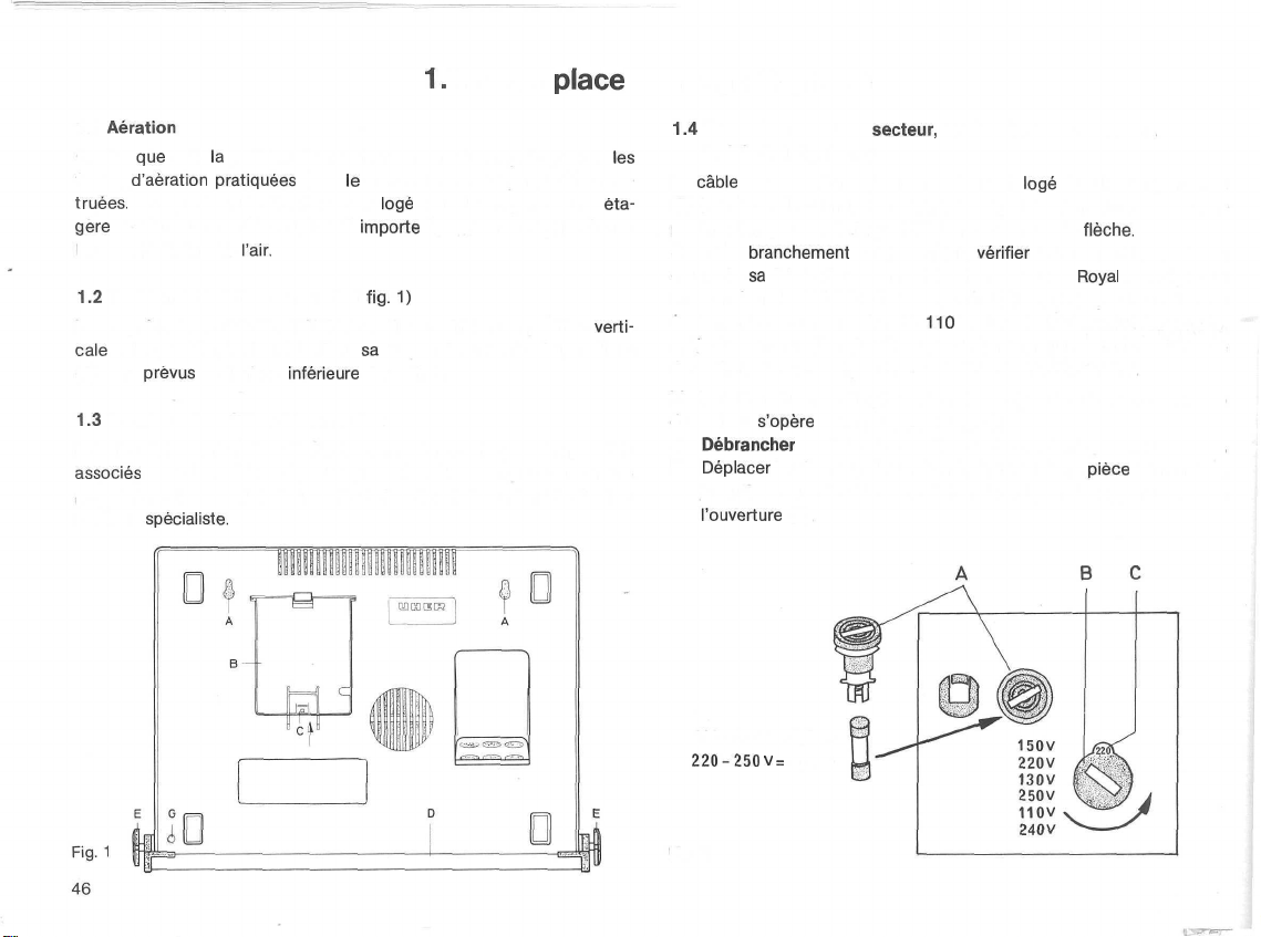
1.
Mise en
place
du magnetophone
1.1 Aeration
Quelle
que
soit
la
position de fonctionnement du magnetophone,
fentes
d'aeration
truees.
Lorsque le magnetophone est
gere
ou dans un meuble musical, il
bonne circulation de
1.2
Position de fonctionnement (voir
Le magnetophone SG 561 ROYAL travaille aussi bien en position
cale
qu'en position horizontale. Pour
(A) sont
prevus
1.3
Longueur des cäbles de connexion
Pour le prolongement des cäbles de connexion qui ne peuvent pas etre
associes
Programme d'accessoires (voir en fin de brochure), il convient de s'adresser ä un
specialiste.
pratiquees
sur la face
avec les cäbles de rallonge enfichables compris dans notre
l'air.
dans
Interieure
le
coffret ne doivent jamais etre obs-
löge
entre les rayons d'une
Importe
egalement de veiller ä une
flg.
1)
sä
Suspension murale, deux oeillets
du coffret.
les
eta-
verti-
1.4
Raccordement sur le
fusible (voir fig. 1 et 2)
Le
cäble
de raccordement sur le secteur est
(B) ä la base du coffret. Pour ouvrir le clapet de fermeture de ce compartiment, repousser le loquet (C) dans le sens de la
Avant le
cours de
une tension de 220 V/50 Hz en courant alternatif. II peut fonctionner
egalement avec une tension de
apres la commutation du selecteur de tension qui se trouve ä la base
du coffret, dans le compartiment du cäble de raccordement.
L'adaptation du magnetophone SG 561 Royal sur une autre tension
du secteur
a)
b)
branchement
sä
fabrication, le magnetophone SG 561
s'opere
Debrancher
Deplacer
jusqu'ä ce que la valeur de la tension disponible apparaisse dans
l'ouverture
110-150 V= 1,2 At
220-250 V =
le cäble de raccordement hors de la prise du secteur.
le selecteur de tension (B) ä l'aide d'une
(C).
0,6 At
secteur,
sur le secteur,
comme suit (voir fig. 2):
tension de fonctionnement,
verifier
110
V, 130 V, 150 V, 240 V ou 250 V,
löge
dans le compartiment
fleche.
la tension disponible. Au
Royal
est regle sur
piece
de monnaie,
Fig.
2
Page 49

c) Pour une tension de
220 V ä 250 V) est ä remplacer par un fusible de 1,2 A. Au moyen
d'une
piece
de monnaie,
cöte du selecteur de tension et
L'adaptation
echange
reference
60 Hz - No. de reference 013170). Ce travail doit etre
ference
1.5
Montage de la poignee (voir
La poignee (D) est
(E)
inserees
tophone en position
basculer la poignee vers
par un cliquet (G). Serrer ensuite ä fond les vis (E).
Pour ramener la poignee dans
les vis (E) et degager (par simple pression) le cliquet (G) accessible sur
la face
poignee et la fixer.
1.6
Couvercle transparent
Le couvercle transparent
chacune de ses faces laterales et deux pattes sur
de 50 Hz sur 60
de
la
poulie du moteur (poulie de moteur pour 60 Hz - No. de
011050)
ä un
specialiste.
dans les trous
Interieure
110
V ä
150
V, le fusible de 0,6 A (tension de
devisser
Hz
et du condensateur (condensateur de moteur pour
fixee
sur le
taraudes
verticale,
l'arriere
sä
du coffret, ä cöte du pied de caoutchouc. Relever la
comporte
le
porte-fusible
inserer
le fusible
ou inversement,
flg.
1 et 3)
coffret
du magnetophone ä l'aide des vis
(F). Pour la mise en
desserrer
legerement
oü
eile
est
position normale de
une touche d'accrochage sur
approprie.
s'effectue
les vis (E) et faire
bloquee
automatiquement
transport,
sä
face
(A) accessible ä
par le simple
confie
de
pre-
place
du magne-
desserrer
arriere.
Lorsque
les deux pattes sont
peut etre rabattu et
Pour
l'ouverture
d'accrochage. Le couvercle peut etre
de son Ouvertüre. II doit toujours recouvrir le magnetophone pendant
les
periodes
1.7
Insertion de la bände magnetique (voir fig. 4)
Avant
d'inserer
des deux pivots de verrouillage des bobines et, par un mouvement de
rotation, aligner ses trois dents avec celles de la base immobile (posi-
tion A). Poser une bobine pleine sur le plateau de gauche et une bobine
vide sur le plateau de droite. Pour caler les bobines, faire tourner ä droite
et respectivement ä gauche la tete des pivots de verrouillage, jusqu'ä
ce qu'elle s'encliquette avec la base immobile (position B) et fixe ainsi
les bobines dans
Derouler
environ 25 cm de la bobine pleine (ä gauche), tendre la bände
sur le levier palpeur gauche et l'introduire
de guidage. Enrouler
deux spires). Avant l'insertion de la bände magnetique, mettre en Position «STOP» le selecteur de
engagees
encliquete.
du couvercle,
de
non-utilisation,
la bände magnetique, degager vers le haut la tete mobile
leur
dans les
position.
l'extremite
fonctions®.
charnieres
il
suffit
de presser sur les deux
alors
afin
d'eviter
de la bände sur la bobine vide (une ou
du coffret, le couvercle
releve,
puls
retire
l'infiltration des
verticalement
touches
ä mi-course
poussieres.
dans la fente
F
©
oooooooooooooo
OOOOOOOOQOOOOOOO
oooooooooooooeoo
OOOOOOOOOOQOOQOS
ooooooooooooooo©
OOOOOQOOO©OOOOOO
oooooooooooooooo
oooooooooooooo
Fig.
3
3
Si
l'arret
automatique en fin de bände entre en action
apres le
demarrage
de l'amorce se trouve encore dans la fente de guidage. Pour
de nouveau le transport de la bände magnetique, renverser la manette
du selecteur de fonctions @
ment
de la manette, le selecteur revient de
«START».
du magnetophone, c'est que la bandelette contact
au-delä
de la position «START». Au reläche-
B
lui-meme
Fig.
immediatement
declencher
dans
sä
position
4
47
Page 50

2. Prises de raccordement
2.1
Prise
«Microphone»
Tous
les
microphones electrodynamiques Stereo ä faible impedance
peuvent etre branches dans cette prise avec des fiches
prises de son stereo,
phones electrodynamiques mono par
K 626. Le cäble d'un microphone mono ä faible impedance peut etre
prolonge
avec
le
d'un microphone stereo
Pour une prise de son mono, il est possible de brancher directement un
microphone ä condensateur
«Microphone». Pour une prise de son Stereo, deux microphones M 646
sont branches par l'intermediaire d'un cäble adaptateur K 626. La fiche
jaune de ce cäble correspond
au canal droit. Si les cäbles de connexion des deux microphones doivent
etre
prolonges,
utiliser le cäble de rallonge K
teur K 626. Une batterie
l'alimentation en courant.
Q
DIN.
il
est de meme possible de raccorder deux micro-
cäble de rallonge K
s'opere
avec le cäble de rallonge K
(p.ex.
le type UHER M 646) dans
alors
au
incorporee
dans les microphones assure alors
l'intermediaire
110.
canal
du cäble adaptateur
Le prolongement du cäble
gauche et la fiche rouge
110
et le cäble adapta-
134.
Pour
la
les
prise
Fig.
W 674
W 774
5
2.2 Prise
Cette prise
cäble est termine par une fiche ä 5
ou W 775). Le raccordement d'un casque
(p.ex. le type UHER W 674 ou W 774)
«Casque» ^ (voir fig. 5)
sert
au raccordement d'un casque d'ecoute stereo dont le
pöles
(p.ex. le type UHER W 675
comportant
s'effectue
deux fiches LS 7
par l'intermediaire du
cäble adaptateur K 633.
L'introduction de la fiche ä 5 pöles (ou de la fiche du cäble adaptateur
K 633) dans la prise «Casque»
parleurs incorpores, ä condition toutefois que
fiche soit
est au contraire
les
tanement
orientee
orientee
haut-parleurs
incorpores et le casque d'ecoute reproduisent
le Programme sonore.
vers
l'exterieur
deconnecte
automatiquement les haut-
l'echancrure
«a» de la
(voir fig. A). Si l'echancrure de la fiche
en direction du magnetophone (voir fig. B),
simul-
48
Fig.
A
2.3 Prise
Cette prise
«Phono
d'entree
stereo ä cellule
II»
-J.
(voir fig. 6)
sert au raccordement direct d'un
piezoelectrique,
dont le cäble de connexion est termine
phonolecteur
Fig.
B
par une fiche DIN. Elle convient de meme au raccordement direct d'un
phonolecteur stereo ä cellule
dernier
possede
un
preamplificateur
magneto-dynamique,
de correction.
ä condition que ce
Le branchement de sources sonores ä haut niveau (p.ex. magnetophone
stereo ä bobines ou ä cassette,
stereo-receiver
ou pupitre de mixage
stereo UHER Mix 500, type A 124) est en outre possible, par l'inter-
mediaire
du cäble de connexion Stereo K 541.
Page 51

2.4 Prise
Cette prise est
d'un magnetophone ä bobines
Stereo ä cellule
magneto-dynamique
des prises et des fiches Standard
le
reliee
mediaire
La prise «Radio/Phono l» admet egalement le raccordement d'un recepteur radio mono, d'un phonolecteur mono ou d'un magnetophone
mono. II faut
prise de la source sonore, avant
phone SG 561
«Radio/Phono
destinee
röle
d'entree (enregistrement) ou de
avec
la
prise «Magnetophone» de
du
cäble
alors
Royal.
l»
A.
au raccordement
piezoelectrique
avec
preamplificateur
de connexion Stereo K 541.
inserer
eventuellement
(voirfig.
6)
d'un
ou
ä cassette Stereo, d'un
ou d'un phonolecteur
de correction,
DIN.
La prise «Radio/Phono l» joue
sortie
(reproduction). Elle est
la
source sonore par l'inter-
l'adaptateur K 837 dans la
d'etablir
la liaison avec le magneto-
recepteur
stereoä
radio Stereo,
phonolecteur
cellule
comportant
2.7 Prise
«Haut-parleur
Cette prise sert au raccordement d'une enceinte acoustique
^ 4 ohms;
production du
est introduite dans la prise
parleur respectif (gauche) incorpore dans le magnetophone est
necte.
l'enceinte acoustique et le
temps le canal gauche.
Un casque d'ecoute comportant deux fiches LS 7
egalement dans la prise «Haut-parleur gauche». Si
est inferieure ä 200 ohms, le volume acoustique tres eleve ä la reproduction risque de detruire le Systeme des deux ecouteurs.
puissance d'entree admissible ^ 6 watts) affectee ä la re-
canal
Si la fiche est introduite dans le sens contraire (voir fig.
gauche»
gauche. Lorsque la fiche de l'enceinte acoustique
43
((voirfig.
comme
represente
haut-parleur
6)
(impedance
par la fig. 6 (A), le haut-
decon-
6—B),
incorpore reproduisent en meme
peut
etre branche
l'impedance
du casque
2.5 Prise A
Cette prise
ou de la telecommande au pied F
L'Akustomat est un interrupteur
demarrage
de l'apparition et respectivement de la disparition d'une onde sonore.
2.6
Cette prise de sortie est
phone SG 561 Royal sur un amplificateur comportant une
monitoring, par
ficateur ä prises «einen») ou d'un cäble de connexion K 563 (amplifi-
cateur ä prises Standard DIN) (voir sous 4.3).
Elle convient de plus au raccordement d'un projecteur automatique
de diapositives, au
du passage des prises de vue dans le projecteur, en conjonction avec
le Dia-Pilot - voir sous
Prise,4
(voirfig.
sert
et
0=
6)
au raccordement de la telecommande ä main F
211,
l'arret
du
transport
(voirfig. 6)
l'intermediaire
moyen
8.).
ainsi que de
electro-acoustique
de la bände
prevue
pour le raccordement du magneto-
d'un cäble de connexion K 562 (ampli-
du cäble de connexion K 911
l'Akustomat F 411.
qui commande le
magnetique,
111
en fonction
entree
de
(commande
Fig.
6
2.8
Prise
«Haut-parleur
Cette prise sert au raccordement d'une enceinte acoustique (impedance
Jj
4 ohms; puissance d'entree admissible
production du canal droit. Lorsque la fiche de l'enceinte acoustique est
introduite dans la prise comme represente par la fig. 6 (A), le haut-
parleur respectif (droit) incorpore dans le magnetophone est
necte.
Si la fiche est introduite dans le sens contraire (voir fig.
l'enceinte acoustique et le haut-parleur incorpore reproduisent en meme
temps le canal droit.
Un casque d'ecoute comportant deux fiches LS 7 peut etre branche
egalement dans la prise «Haut-parleur droit». Si
est inferieure ä 200 ohms, le volume acoustique tres eleve ä la repro-
duction risque de detruire le Systeme des deux ecouteurs.
droit»
<l
II
(voirfig.
6)
J>
6 watts) affectee ä la re-
l'impedance
II«
decon-
6-B),
du casque
49
Page 52

Les
3. Les organes de
chiffres
qui facilitent l'identification des organes de manoeuvre
manoeuvre
decrits
ci-dessous,
et
sont
leurs
reportes
fonctions
dans la gravure du
depliant
(en fin de
brochure).
3.1 Touche «MICRO» ©
L'actionnement de cette
che
dans la prise «Microphone» et
dans la prise
tion enfoncee et reprend
ment.
3.2 Regleurs du niveau de modulation L @ et R ©
pour
Les boutons L @ et R (3) servent ä ajuster le niveau de modulation du
microphone Stereo
sonore Stereo branchee dans la prise «Radio/Phono l». Le bouton
rieur L @ est affecte au
bouton
metre
3.3 Regleurs du niveau de modulation L © et R ©
pour PHONO II
Les boutons L 0 et R © servent ä ajuster le niveau de modulation de
la source sonore Stereo branchee dans la prise «Phono II». Le bouton
superieur L @
Le bouton
metre (7).
3.4 Modulometre © pour le canal gauche
En regime d'enregistrement, le modulometre © indique
crete du niveau de modulation dans le canal gauche. En regime de reproduction,
50
«Radio/Phono
MICRO-RADIO/PHONO
Interieur
(T).
est affecte au canal gauche et agit sur le
inferieur
II
affiche
touche
enclenche
deconnecte
l». Cette touche s'accroche dans
sä
position de repos apres un nouvel actionne-
l
branche
R ® est affecte au canal droit et agit sur le modulo-
R © est affecte au canal droit et agit sur le modulo-
les valeurs de crete du niveau de
dans la prise «Microphone» ou de la source
canal
gauche et agit sur le
le
microphone
la source sonore branchee
sortie.
Stereo bran-
sä
modulometre©.
modulometre©.
les
valeurs de
posi-
supe-
Le
3.5 Modulometre @ pour le canal droit
En regime d'enregistrement, le modulometre © indique les valeurs de
crete du niveau de modulation dans le canal droit. En regime de reproduction,
II
affiche les valeurs de crete du niveau de sortie.
3.6 Touche «MITHÖREN» (VORBAND/HINTERBAND)
Cette touche
dans
l'inscription) et reprend
(HINTERBAND = monitoring en retard sur l'inscription). En position
HINTERBAND, on peut
le Signal est
sur la bände. En position VORBAND par contre, le Signal de la source
sonore est
tion
repetee
l'execution
3.7 Bouton «MULTIPLAY/ECHO» ©
En regime Multiplay (voir sous 7.4), ce bouton sert ä regier le niveau du
Programme sonore ä
Operation, un autre Programme est
piste 2. Le niveau de ce Programme est regle avec les organes de
manoeuvre respectifs de la source sonore branchee sur le
phone SG 561
En regime d'enregistrement mono avec
bouton ® sert ä regier le niveau du Programme qui
de lecture sur la tete d'inscription, c'est-ä-dire ä
de
l'effet
sert
au
contröle
sä
position enfoncee (VORBAND = monitoring en avance sur
preleve
capte
et reproduit pendant son inscription. Par la commuta-
de VORBAND sur HINTERBAND, on peut donc comparer
sonore originale avec son enregistrement.
reporter
Royal.
d'echo.
auditif ä l'enregistrement. Elle s'accroche
sä
position initiale apres un nouvel actionnement
verifier
la
qualite
de la prise de son, du fait que
et reproduit
immediatement
de la piste 1 sur la piste 2. Pendant cette
enregistre
effet
©
apres on inscription
simultanement
d'echo (voir sous 7.1), le
parvient
determiner
sur la
magneto-
de la tete
l'intensite
Page 53

En regime d'enregistrement et en Position «MONO/DIA-PILOT» ou
«STEREO/DIA-PILOT» du selecteur de
pistes©,
l'actionnement du bouton © permet d'inscrire sur la bände les impulsions de commande qui,
ä la reproduction,
un projecteur de diapositives.
declenchent
le changement des prises de vue dans
L'inscription
des
«tops»
de commande
doit etre executee separement, ä savoir apres J'enregistrement du com-
mentaire
parle
et/ou du fond musical qui accompagnent la projection
des diapositives (voir sous
8.).
3.11 Selecteur de pistes ®
Ce selecteur permet de
modulometre,
quatre diodes luminescentes signalent la fonction d'en-
registrement ou de reproduction
choisir
11
modes
enclenchee
operatoires.
Au-dessous du
et la piste respective. Les
deux diodes ä lumiere rouge caracterisent la ou les pistes en cours
d'inscription, tandis que les diodes ä lumiere verte caracterisent la ou
les pistes en cours de lecture. Dans le tableau suivant, les points noirs
representent
les diodes
allumees.
3.8 Double regleur de
pour l'accentuation ou
tonalite
HÖHEN
l'attenuation
©/TIEFEN
®
des aigus et des graves, en
com-
mun dans les deux canaux. Le bouton superieur © est affecte aux
aigus et le bouton
Interieur
© aux graves.
3.9 Double regleur «LAUTSTÄRKE» pour le canal gauche @
et le canal droit ®
pour le
reglage
separe
du volume acoustique dans les deux canaux
Stereo. Le bouton superieur ® est affecte au canal gauche et le bouton
Interieur
® au canal droit.
3.10 Touche «AUFNAHME» ®
Cette
touche
met
le
magnetophone
demeure
accrochee
dans
sä
selecteur de fonctions ® est
en regime «Enregistrement». Elle
Position de travail, seulement lorsque le
deplace
de la Position «STOP» vers la
Position «PAUSE» ou «START». Dans les positions «PAUSE» et «START»
du selecteur de fonctions
ne peut pas etre
enfoncee.
®,
la touche «AUFNAHME» est
bloquee
et
ECHO 2
ECHO 1
SYN.PLAY 2
SYN.PLAY 1
MONO 2
MONO 1
STEREO
MULTIPLAY 1
MULTIPLAY 2
MONO/DIA-PILOT
STEREO/DIA-PILOT
Enregistrement Reproduction
Can.1
Can.2
Can.1
o • o o
o o o
Can.2
• o o o
51
Page 54

La figure ci-dessous montre le sens de defilement, ainsi que la Position
des pistes en technique
et «4 pistes»,
les
la bände (la bobine pleine de droite prend la
gauche). L'enregistrement peut etre
«bipiste», la bände est
et doit etre
reembobinee.
«bipiste»
et «4 pistes». En regime mono
«bipiste»
bobines sont ä intervertir apres le premier passage de
place
de la bobine vide de
alors
poursuivi. En regime Stereo
completement
En regime
utilisee
apres son premier passage
stereo
«4 pistes», deux pistes sont
encore disponibles apres l'interversion des bobines.
Sterec
Mono + Stereo
3.12 Selecteur de vitesses ®
pour le
choix
d'une des quatre vitesses de defilement et pour l'enclenchement du magnetophone. En position «0» du selecteur de vitesses,
l'alimentation
le moteur
alors
en courant est
d'entramement
comme
amplificateur HiFi mono ou Stereo (voir sous
deconnectee.
est deconnecte. Le magnetophone travaille
En position «VERSTÄRKER»,
10.).
3.13 Selecteur de fonctions ©
pour
l'enclenchement
des fonctions
inherentes
au
transport
de la bände,
ä savoir «STOP», «PAUSE» et «START». Le selecteur de fonctions ne
peut etre actionne que si le curseur de reembobinage @ se trouve
dans
sä
position mediane.
Le
deplacement
«START» deconnecte le Systeme
du selecteur de fonctions
d'arret
automatique en fin de bände.
au-delä
de la position
L'amorce de la bände qui se trouve dans la fente de guidage est alors
transportee
roulee
ä la vitesse de defilement respectivement choisie et en-
sur la bobine vide.
52
Stereo
3.14 Curseur de reembobinage
pour le defilement
la bände
magnetique.
accelere
Le curseur de reembobinage
(S)
en avant
(^-^)
et en
arriere
(-^
s'accroche
^)
dans
de
sä
position de repos mediane, ainsi que dans ses deux positions extremes
gauche et droite. II ne peut etre actionne que dans la position «STOP»
du selecteur de
3.15
Compteur avec touche de rappel ®
L'actionnement
sition «0000». Au
fonctions©.
de la touche de rappel
debut
de chaque enregistrement,
ramene
le compteur dans
il
est judicieux d'en-
sä
Po-
foncer la touche de rappel ou de noter la position du compteur, afin de
pouvoir retrouver rapidement
lors
de la reproduction.
certains
passages du Programme sonore
Page 55

4. Raccordement du magnetophone sur l'amplificateur d'une chame HiFi
Les exemples suivants representent les montages adoptes le plus frequemment pour les
permettent ä tout specialiste de realiser un autre montage et d'etablir les connexions correctes.
4.1 Raccordement du magnetophone sur un amplificateur
ä prises Standard
La figure 7 montre sous une forme schematique le raccordement du
magnetophone sur un amplificateur HiFi ä prises Standard DIN pour les
operations
sources sonores,
chees sur les entrees respectives de l'amplificateur qui est
avec
cäble
u
n enregistrement avec toutes les sources sonores branchees sur l'amplificateur, au cours de
«MICRO» (T) ne doit pas etre
Eien que des microphones puissent etre
HiFi,
d'enregistrement et de reproduction. Toutes les autres
la
prise
«Radio/Phono
de connexion Stereo K 541. II est ainsi possible de
II
est
preferable
DIN
p.ex.
recepteur
leur
de les brancher directement dans la prise
radio,
tourne-disques, etc. sont bran-
l» du magnetophone, par
reproduction par la chame HiFi. La touche
enfoncee.
branches
sur un amplificateur
lui-meme
l'intermediaire
proceder
«Micro-
relie
du
ä
chames
phone»
du magnetophone. La touche «MICRO» (T) est ä actionner
ment pour les enregistrements
Pour le
contröle
registrements microphoniques,
d'ecoute
en position «HINTERBAND» (monitoring en retard sur l'inscrip-
tion) de ia touche
4.2 Raccordement du magnetophone sur un amplificateur
sans prises Standard DIN
La figure 8 montre sous une forme schematique le raccordement du
magnetophone sur un amplificateur HiFi ne
Standard DIN. Dans ce cas
sont branchees sur les entrees respectives de l'amplificateur. Pour les
HiFi. Les informations techniques
microphoniques.
auditif des prises de son et
il
est
recommande
«MITHÖREN»®.
egalement,
particulierement
comportant
toutes les autres sources sonores
donnees
sous
12.
seule-
des en-
d'utiliser un casque
pas de prises
K551
Fig.
7
Page 56

prises de son,
avec la prise
nexion K 551. Pour les reproductions, la prise
gnetophone est reliee avec la prise d'entree «Magnetophone» de l'ampli-
ficateur, ä l'aide d'un autre cäble de connexion K 551. La fiche jaune
du cäble correspond au cäble Stereo de
canal
Stereo de droite. La touche «MICRO» (T) ne doit pas
sauf pour les enregistrements microphoniques ä travers la prise «Microphone».
4.3 Raccordement du magnetophone sur un amplificateur
ä prise d'entree «Monitor»
La figure 9 montre le montage du magnetophone avec un amplificateur
HiFi qui possede une prise d'entree «Monitor» et une touche pour
la
sortie
«Magnetophone» de l'amplificateur est reliee
«Phono
II» du magnetophone, au moyen du
«Radio/Phono
gauche
et la fiche rouge au
cäble
etre
de con-
l» du ma-
enfoncee,
moni-
toring en avance ou en retard sur l'inscription. En cas de prise de son,
la sortie «Magnetophone» de l'amplificateur est reliee avec la prise
«Phono II» du magnetophone, par
K 551 (amplificateur ä prises
(amplificateur ä prises Standard
Pour les reproductions, la prise d'entree «Monitor» de l'amplificateur est
reliee avec la prise £ c3"S
connexion K 562 (amplificateur ä prises «cinch») ou du cäble de connexion K 563 (amplificateur ä prises Standard DIN). La fiche jaune du
cäble correspond au canal Stereo de gauche et la fiche rouge au canal
Stereo de droite. Avec un
trement peut voir Neu avant ou apres l'inscription, ä travers les hautparleurs de la
d'ecoute Stereo est inutile. (Pour la
et du
regleur
tions
d'emploi
4.4 Raccordement du magnetophone sur un receiver,
un poste radio ou un meuble musical
Le branchement du magnetophone
un cäble de connexion Stereo K 541. Pour une prise de son ä partir d'un
phonolecteur,
le meuble musical. Pour un enregistrement microphonique, le microphone
est branche directement dans la prise «Microphone» du magnetophone
et la touche «MICRO» (T) est enfoncee.
En cas d'enregistrement d'un programme radiodiffuse ou d'un disque,
le monitoring en avance ou en retard sur l'inscription
decrit sous 4.3. Pour le contröle auditif des en,registrements microphoniques,
II
chame
HiFi, si bien que le branchement d'un casque
de volume «Monitor» de l'amplificateur, consulter les instruc-
respectives.
ce dernier est branche sur le receiver, le poste radio ou
est
preferable
d'utiliser un casque d'ecoute Stereo.
l'intermediaire
«cinch»)
du magnetophone, au moyen du cäble de
tel
ou du cäble de connexion K 541
DIN).
montage, le contröle auditif d'un enregis-
manoeuvre
s'opere
du cäble de connexion
de la touche «Monitor»
comme decrit sous
s'effectue
4.1,
comme
avec
Page 57

Attendu
que
la
qualite
d'enregistrement
grand soin (voir sous 5.23).
depend
5. Regime d'enregistrement
surtout du
reglage
correct du niveau
demodulation,
cette Operation doit etre
executee
avec
le
plus
5.1 Methode d'enregistrement pour
Un enregistrement
1.
Brancher la souroe sonore voulue et la mettre en circuit. Toutes
autres sources sonores peuvent rester
mais doivent etre
prise «Microphone» est
touche©
2. Etablir la liaison avec le secteur
3. Regler le selecteur © sur la vitesse de defilement choisie (l'alimentation en courant du magnetophone est en
4. Inserer une bände magnetique,
selecteur de pistes ® dans la position correspondant au
ratoire
5. Enfoncer la touche
abaissee
«PAUSE».
6. Actionner la touche de rappel du compteur ® ou noter la position
de ce dernier, afin de faciliter la recherche
passages de l'enregistrement.
7. Regler le niveau de
R ®, resp. L © et R ©. A cet
ce que les aiguilles des deux
graduation «0 dB» aux valeurs de niveau les plus
gramme sonore.
s'effectue
deconnectees.
enclenche
voulu.
«AUFNAHME»®,
et mettre le selecteur de fonctions ® dans
modulation
amateurs
en principe de la fapon suivante:
Un microphone
d'energie.
comme
optimal avec les boutons L @ et
effet,
modulometres
presses
reliees
avec le magnetophone,
branche
ou
deconnecte
meme
decrit
la maintenir dans
manoeuvrer les boutons jusqu'ä
ä l'aide de la
temps
enclenchee).
sous 1.7 et mettre le
sä
ulterieure
© et (7)
de
devient
elevees
dans la
mode
sä
position
position
certains
du pro-
les
ope-
sur la
8.
Deplacer
marrer le
commencer.
9. Pour interrompre
le selecteur de fonctions ® dans
tophone demeure en
10. Apres le defilement complet de la bände magnetique,
vide de gauche) et poursuivre l'enregistrement.
de son Stereo en «bipiste»,
nouvelle bände).
11.
Pour
est
BAND» (monitoring en retard sur l'inscription) de la touche «MITHÖREN» ®. En effet, s\ le monitoring s'effectue par
de
nomene
sifflement.
remarquer
phone.
12.
Apres la prise de son, inscrire les principales
niere
sur l'amorce de la bände, sur la bobine et sur la
le selecteur de fonctions ® sur «START» pour faire
transport
les bobines (la bobine pleine de droite prend la
l'ecoute
preferable
haut-parleurs,
de
Le monitoring par casque d'ecoute permet par contre de
immediatement
et
d'eliminer
(vitesse de defilement, mode
en avant de la bände. L'enregistrement peut
momentanement
regime
en monitoring d'un enregistrement par microphone,
d'utiliser un casque d'ecoute, en position «HINTER-
un volume sonore excessif risque de causer un
reaction
acoustique et par
ces derniers par un changement de position du micro-
le transport de la bände, ramener
sä
position «PAUSE». Le magne-
d'enregistrement.
reembobiner
la
presence
operatoire,
la bände et inserer une
consequent
eventuelle de bruits parasites
donnees
Programme
place
de la bobine
(S'il
s'agit d'une prise
l'intermediaire
l'apparition d'un
de cette der-
enregistre)
botte
de la bobine.
intervertir
de-
il
phe-
55
Page 58

5.2 Methode d'enregistrement pour amateurs
5.21 Raccordement des sources sonores
Brancher
en tenant compte des indications du chapitre 4.
sonores peuvent rester
source sonore
Au cas oü la source sonore branchee dans la prise
une tension de
etre
d'examiner si, compte tenu du cäblage des contacts et des
d'entree,
«Phono
merce (cäblage en croix des broches 1-3 et 4-5) ne procure pas des
conditions plus favorables pour l'enregistrement.
Lorsque la source sonore branchee dans la prise «Phono II» a une ten-
sion de sortie tres faible (la plage de reglage
et R © est atteinte
de
d'un adaptateur, ne fournit par de meilleurs
Consulter
5.22 Alimentation sur le secteur d'energie
Lors de la
ment
de raccordement hors de la prise du secteur d'energie, avant l'echange
du fusible, l'adaptation du magnetophone sur une autre tension ou le
les
sources sonores
utilisee
sortie
tres
manoeuvres
II» par rintermediaire d'un adaptateur en vente dans le
meme
les instructions
que dans
le branchement de la source sonore en question dans la prise
lors
si son
transfert
eventuellement
premiere
mise en service du magnetophone, suivre attentive-
donnees
comme
decrit
raccordees
pour l'enregistrement doit etre mise en circuit.
elevee
de l'ajustage du niveau de modulation),
dans la prise «Radio/Phono l» par rintermediaire
un
sur
le
(les boutons L @ et R (3) ne peuvent
leur
plage de reglage
specialiste
sous 1.4.
ä ce sujet.
Interesses
sous
2.1,
Toutes
magnetophone,
«Radio/Phono
inferieure),
superieure
resultats.
Debrancher
des boutons
toujours le
2.3 et
2.4.,
les sources
mais
il
impedances
tout
seule
l» a
convient
com-
L©
exammer
cäble
56
nettoyage du coffret avec un Chiffon humide. Apres l'enclenchement du
magnetophone (choix de la vitesse de
des deux modulometres doivent s'allumer.
5.23 Reglage d'essai du niveau de modulation
la
et prise de son
Le reglage d'essai du niveau de modulation
son, c'est-ä-dire sans
apres l'insertion d'une bände
«AUFNAHME» ® et le
Position «STOP» dans
Manceuvrer
phone
branchee dans la prise «Radio/Phono l») ou les boutons L © et R (5)
(enregistrement ä partir d'une source sonore branchee dans la prise
«Phono II»), de
vient sur la graduation «0 dB» aux valeurs de niveau maximales de
cution sonore originale.
II
Importe
tion. Lorsque le niveau de modulation est trop
modulometres
surmodulation
le niveau de modulation est par contre trop faible (les aiguilles des
modulometres n'atteignent pas la graduation «0 dB»), la reproduction
manque de
Apres
selecteur de fonctions @ est
les boutons L @ et R @ (enregistrement ä partir d'un micro-
branche
d'executer
limpidite
le
reglage d'essai, le transport de la bände
transport
deplacement
sä
Position «PAUSE».
dans la prise
facon
que les aiguilles des modulometres © et @
minutieusement le reglage du niveau de modula-
devient
jusque dans la plage rouge), il se produit une
qui se manifeste par une distorsion ä la lecture. Lorsque
et peut etre
deplace
defilement),
de la bände. Un
magnetique,
du selecteur de fonctions ® de
«Microphone»
alteree
sur «START».
les lampes
s'opere
tel
reglage est possible
l'actionnement de la touche
ou d'une source sonore
eleve
par un
souffle
demarre
avant la prise de
(les aiguilles des
d'eclairage
sä
de-
l'exe-
parturbateur.
des que le
Page 59

6. Regime de reproduction
6.1 Methode de reproduction pour
La reproduction peut
pores
du magnetophone. En cas de reproduction avec un casque
d'ecoute, on peut mettre en circuit ou
loges
dans le magnetophone (voir sous 2.2). Si
par
l'intermediaire
tophone, on peut
parleurs
Interieurs
La reproduction
1.
Inserer
2. Mettre le selecteur de pistes © dans la position correspondant au
3. Amener le selecteur de fonctions ® dans
4. Regler le volume acoustique dans les deux canaux Stereo avec les
la bände
selecteur © sur la vitesse de
son.
mode
operatoire
boutons
boutons ® et
tiques d'une chalne HiFi, le
tonalite
s'execute
l'amplificateur.
s'effectuer
des enceintes acoustiques branchees sur le magne-
egalement
(voir sous 2.5 et 2.6).
s'effectue
@et®.
©.
en principe de la
magnetique,
choisi pour
Ajuster
En cas de reproduction avec les enceintes acous-
ä l'aide des organes de
amateurs
directement avec les
rendre
efficaces
comme
defilement
la
la
tonalite (aigus
reglage
presses
etages
deconnecter
la
reproduction a Neu
ou
inefficaces
facon
suivante:
decrit
sous 1.7 et mettre le
adoptee
prise de son (voir sous 5.1.12).
sä
position «START».
et
graves) ä l'aide
du volume acoustique et de la
manoeuvre
finaux incor-
les
haut-parleurs
les haut-
pour la prise de
des
respectifs de
Apres le passage complet de la bände et l'interversion des bobines
(la bobine pleine de droite prend la
gauche), poursuivre la reproduction sur les pistes restantes.
6.2 Methode de reproduction pour amateurs
La
qualite
de la reproduction
prise de son. Le meilleur amplificateur et les meilleures enceintes acoustiques ne peuvent pas corriger un enregistrement execute avec un niveau
de modulation incorrect. Pour le contröle d'une reproduction en regime
Stereo, on peut
ference
un casque d'ecoute. Une perte des aigus ä la reproduction
coule
frequemment
sous
11.)
En regle
ceintes acoustiques qui sont branchees soit sur l'etage final
du magnetophone, soit sur l'amplificateur d'une
dernier cas, consulter le chapitre 4.
sur l'amplificateur d'une chalne HiFi». Toutes les autres
identiques ä celles
utiliser
generale,
de l'encrassement des
la reproduction s'effectue par
decrites
depend
soit les haut-parleurs
sous 6.1.
place
de la bobine vide de
Interesses
essentiellement
incorpores,
tetes
chalne
«Raccordement
de
celle
de la
soit de
magnetiques
l'intermediaire
(2X
HiFi. Dans ce
du magnetophone
operations
(voir
d'en-
10 watts)
pre-
de-
sont
57
Page 60

Les
possibilites
de
truquage
decrites
ci-dessous
existent
T.Truquages
aussi
bien en version bipiste
sonores
qu'en
Version quatre pistes du magnetophone.
7.1 Enregistrement
Le magnetophone SG 561
et de reverberation, variables en fonction de la vitesse de defilement.
Les
effets
suivants sont obtenus avec
filement:
Effet de reverberation en
Effet d'echo en 9,5 cm/sec.
Effet d'echo avec reverberation en 4,7 cm/sec.
Effet d'echo avec reverberation
Un enregistrement avec effet d'echo
1.
Regler la vitesse de defilement
2. Brancher la source sonore comme
cas d'enregistrement par microphone (prise Q L), enfoncer la
touche
3. Selon la piste
4. Regler le niveau de modulation avec le bouton L @ et
5. Pour le
58
«MICRO»©.
de pistes © en position «ECHO 1» (enregistrement
ou 4) ou en position «ECHO 2» (enregistrement sur la piste 2 ou 3).
Lorsque
de pistes © doit toujours etre regle en position «ECHO
de l'effet d'echo ou de reverberation avec le bouton
ECHO»®.
contröle
de
preference
ce casque dans la prise «Casque», de
incorpores
monophonique
Royal
adoptee
le magnetophone est
auditif d'un enregistrement avec effet d'echo, adopter
un casque
soient
deconnectes
avec
effet
se
prete ä la
19
cm/sec.
prolongee
s'execute
selon
pour
l'enregistrement, mettre
utilise
d'ecoute
(voir sous 2.2). La touche
realisation
les
differentes
en 2,4 cm/sec.
comme
l'effet
desire.
decrit
sous
en version bipiste, le selecteur
W 775. Introduire les fiches de
fapon
d'echo
suit:
2.1,
que les
d'effets
d'echo
vitesses de de-
2.3 et 2.4. En
le
selecteur
sur
la piste 1
1».
l'intensite
«MULTIPLAY/
haut-parleurs
«MIT-
HÖREN» ® doit se trouver dans
toring en retard sur l'inscription).
La reproduction
selecteur de pistes © peut etre
«ECHO 1» ou «ECHO 2», soit dans la position «MONO 1» ou
«MONO 2».
7.2 Enregistrement
Des enregistrements
realises
au
moyen
Proceder
1.
2. Enclencher le magnetophone en
3. Brancher le cäble de monitoring K 563 dans la
4.
5. Si la source sonore est
comme suit:
Mettre le selecteur de pistes © en position «STEREO».
ä 6 broches) et la prise ^ (fiche
Brancher
ment par
phone» puis enfoncer la touche
modulation avec les boutons L @ et R (3). La touche «MITHÖREN»
® ne doit pas etre
avec les deux boutons L © et R
toring K 563 peut etre
de modulation est alors regle avec les deux boutons L ® et
tandis que l'intensite de
et R®.
s'opere
stereophonique
stereophoniques
du
cäble
la
source'"sonore
microphones,
enfoncee.
de monitoring K 563.
raccorder ces derniers dans la prise «Micro-
raccordee
enfiche
sä
position «HINTERBAND»
comme pour un enregistrement normal. Le
alors
regle soit dans la position
avec effet d'echo
avec effet d'echo peuvent etre
regime
d'enregistrement.
prise ^ c3"e(fiche
ä 5
braches).
dans
la
prise£.
«MICRO»©.
Ajuster l'intensite de l'effet d'echo
©.
dans la prise
egalement
l'echo
est
ajustee
En cas
Regler le niveau de
.J.,
le cäble de moni-
dans la prise
avee les boutons
£.
d'enregistre-
Le niveau
(moni-
R®,
L@
Page 61

7.3 Montage Synchroplay
La methode Synchroplay
registrement simultane de
possibilites
seul
Le montage Synchroplay
photographes
difficulte
Proceder
1.
Mettre
2. Enfoncer la touche «MITHÖREN» ® (position «VORBAND» =
3. Brancher un microphone dans la prise
4. Brancher un ecouteur (p.ex. ecouteur
de truquage sonore, p.ex. duo
interprete.
toring en avance sur l'inscription). Amener sur
deux boutons ®
touche
W 214) ou un casque d'ecoute Stereo (p.ex. W 674 ou W 774)
dans la prise
deux fiches du casque d'ecoute Stereo.
Elle est
et les
gräce ä la conception
comme
suit:
le
selecteur de pistes ® dans
«MICRO»©.
consiste ä reproduire
la
representee
presente
cineastes
et
® du
double
«Haut-parleur
une piste pendant
piste parallele. Elle procure
vocal
ou instrumental avec un
schematiquement
un
interet
tout
amateurs. Sa realisation
etudiee
du
magnetophone
sä
Position
regleur «LAUTSTÄRKE».
«Microphone»
electromagnetique
gauche».
Inserer
par la
particulier
n'offre
SG 561
«SYN.PLAY
leur
butee
et enfoncer la
l'une
dans l'autre les
differentes
gauche les
miniature
l'en-
flg.
10.
HD((O
d
Fig.
10
pour
les
aucune
Royal.
1».
moni-
5. Executer le premier enregistrement par microphone et regier le niveau de modulation avec le bouton L @ qui agit sur le modulo-
metre®.
6. Reembobiner la bände
ment.
7. Mettre le selecteur de pistes ® dans
8. Mettre en
9. Enfoncer la touche «AUFNAHME» ® et
fonctions ® sur «START». Suivre la reproduction du Premier en-
registrement ä l'aide de l'ecouteur ou du casque d'ecoute (le volume
acoustique se regle avec le bouton superieur ® du double regleur
«LAUTSTÄRKE»),
ment par microphone, en synchronisme sur la piste parallele. Regler
le niveau de modulation avec le bouton superieur L @ et
le
10.
A la fin du
cher l'ecouteur (ou le casque d'ecoute).
11. Pour la reproduction d'un enregistrement Synchroplay, mettre le
selecteur de pistes ® en position «STEREO» et la touche «MIT-
HÖREN» ® en position «HINTERBAND».
de la bände.
7.4 Montage Multiplay
La methode Multiplay permet d'obtenir des
par la surimpression de l'enregistrement d'une piste sur une autre piste,
pendant l'inscription simultanee d'un nouvel enregistrement. Si une teile
Operation est
est
enregistre
Multiplay n'est toutefois possible que si les deux pistes
(pistes 1 et 2 en technique «bipiste» ou pistes 1 et 3, resp. 2 et 4 en
technique «4 pistes») ne sont pas occupees par une prise de son
rieure. La fig.
place
modulometre
second
repetee
avec un seul
11
montre le principe de la methode Multiplay.
magnetique
l'ecouteur
En
©
ou le casque d'ecoute.
meme
enregistrement, reembobiner la bände et
plusieurs fois, un orchestre complet (p.ex. sextuor)
executant.
jusqu'au
temps, executer le second enregistre-
La realisation d'un enregistrement
debut
de l'enregistre-
sä
position «SYN.PLAY 2».
deplacer
Declencher
effets
le selecteur de
observer
le
transport
sonores
tres
necessaires
debran-
varies
ante-
59
Page 62

Proceder de
1. Mettre
2. Brancher un casque d'ecoute
3. Amener sur
4. Regler le selecteur de vitesses ® sur la valeur voulue
5. A la fin de l'enregistrement, reembobiner la bände magnetique.
60
la
fafon
suivante:
le
selecteur de pistes © dans
Brancher
un
microphone dans la prise
raccordement d'un microphone Stereo,
nique
affecte
au
canal
gauche est
«MICRO»©.
sä
position
Position «PAUSE». La touche «MITHÖREN» ® doit se trouver en
Position «HINTERBAND» lorsque la bände
BAND» lorsque la bände est immobile.
«Haut-parleur
la prise «Casque»), ä savoir de teile facon que
corpores
fiche rouge du casque d'ecoute sur la fiche jaune. Le casque d'ecoute
branche dans la prise «Haut-parleur gauche» (ou dans la fiche jaune
du
cäble
second casque d'ecoute branche dans la prise «Haut-parleur droit»
(ou dans la fiche rouge du cäble adaptateur K 633) est destine ä
«l'ingenieur
une
impedance
de
defilement
pour les enregistrements
tion avec le bouton superieur L @ apres avoir
«MITHÖREN» (8) (position
HÖREN»®,
«HINTERBAND»)
Proceder ä l'enregistrement sur la piste 1 de la facon habituelle.
Mettre le selecteur de pistes © dans
et faire
ment.
Enfoncer la touche
abaissee
soient
adaptateur K 633) est destine ä
du son». Les deux casques W 674 ou W 774 doivent avoir
demarrer
L'executant suit la reproduction du premier enregistrement ä
et mettre le selecteur de fonctions ® dans
(p.ex.
gauche» et dans la prise
deconnectes
superieure
sä
butee
de 19 cm/sec. et 9,5
afin qu'elle reprenne
et
deplacer
le
transport
(voir sous 2.2, 2.7 et 2.8).
ä 200 ohms (voir sous 2.7 et 2.8).
gauche le bouton
Multiplay)
«VORBAND»).
leselecteurde
de la bände pour le second enregistre-
sä
position «MULTIPLAY 1».
«Microphone»
seul
le Systeme micropho-
efficace).
«AUFNAHME»®,
defile
W 674 ou W 774) dans la prise
«Haut-parleur
l'executant,
«MULTIPLAY/ECHO»®.
cm/sec.
sont
et ajuster le niveau de modula-
Actionner la touche «MIT-
sä
position de repos (= position
fonctions ®
sä
position «MULTIPLAY 2»
(en cas de
Enfoncer la
la maintenir dans
et en position «VOR-
les
haut-parleurs
enfonce
touche
droit» (ou dans
Inserer
tandis que le
(les
vitesses
recommandees
la touche
sur
«START».
sä
in-
la
l'aide de son casque (le volume acoustique se regle avec le bouton
superieur ® du double
chronisme au second enregistrement. «L'ingenieur de son»
dans son casque les deux enregistrements. En position «HINTER-
BAND» de la touche
enregistrement avec le bouton L (5) et
ä
reporter
en surimpression avec le bouton
II surveille le
ments et le corrige ä
6. Pour le
magnetique, mettre le selecteur de pistes ® dans
«MULTIPLAY 1» et reprendre les operations decrites ci-dessus A
chaque nouvel enregistrement, commuter le selecteur de pistes®
de
sä
vice versa, jusqu'ä
7. Lors de la reproduction d'un enregistrement Multiplay, veiller ä ce
que le selecteur de pistes © se trouve dans
si l'enregistrement Multiplay a
ou respectivement en position «MONO 2», si l'enregistrement a
termine
identiques ä celles
trements normaux.
l l l l l l l l l l l
Pour la
realisation
d'un second
Mix 500, type A 124). Les operations ä
instructions d'emploi du pupitre de mixage.
rapport
troisieme
position «MULTIPLAY 1» dans
en position «MULTIPLAY 2». Les autres manoeuvres sont
magnetophone
regleur
«LAUTSTÄRKE») et
«MITHÖREN»®,
du volume acoustique des deux enregistre-
volonte.
enregistrement, reembobiner de nouveau la bände
l'achevement
etetermineen
dejä
decrites pour la reproduction des enregis-
•
1 1 1 1
d'un enregistrement Multiplay Stereo, on doit disposer
et d'un pupitre de mixage
il
regle le niveau du second
celui
sä
position «MULTIPLAY 2» et
du montage sonore.
1
executer
procede
de la premiere inscription
«MULTIPLAY/ECHO»®.
sä
position «MONO 1»,
position «MULTIPLAY 1»,
sont decrites dans les
sä
(p.ex.
en syn-
percoit
Position
ete
Fig.
11
UHER
Page 63
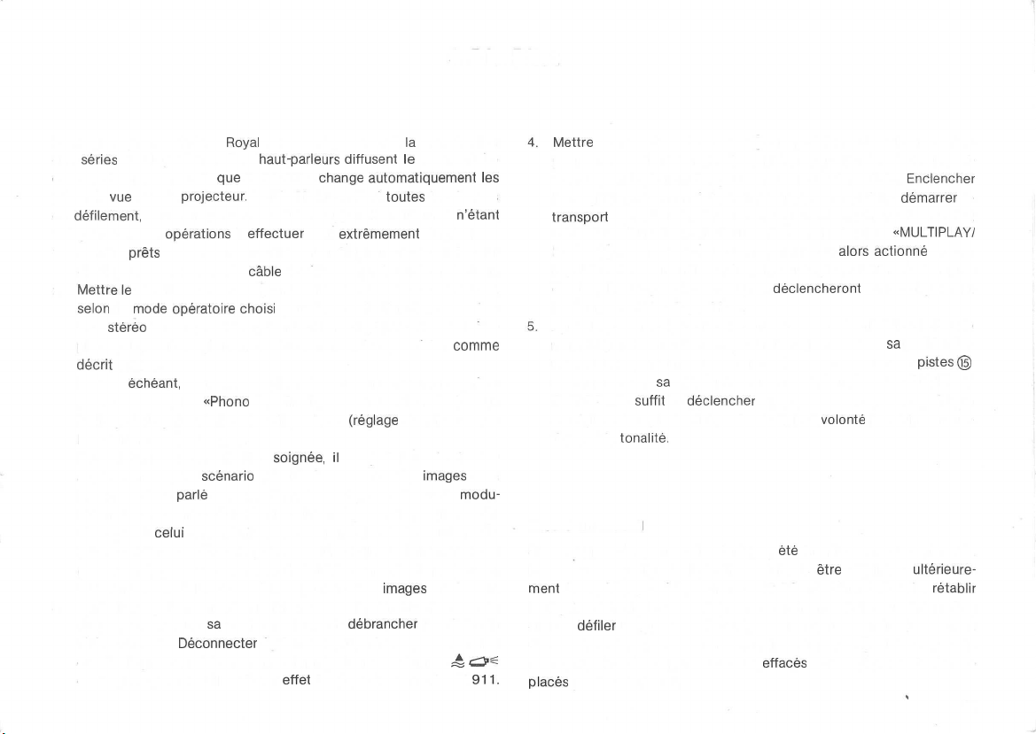
8. Dia-Pilot
Le magnetophone SG 561
des
series
de diapositives. Ses
et le motif musical, tandis
prises de
de
indispensable, les
1. Rendre
2.
3. Apres l'enregistrement, reembobiner la bände, remettre le magasin
vue
dans le
defilement,
de diapositives. Brancher le
Mettrele
selon
tion
phone). Pour l'enregistrement du commentaire, proceder
decrit
Le cas
phone dans la prise
bruitage ä la presentation des diapositives
les boutons L © et R © ).
Pour obtenir une sonorisation
auparavant un petit
le commentaire
lation du commentaire ä l'aide du bouton L @ (ou des boutons L@
et R (D ) et
(ou des boutons L © et R © ). Au cours de l'enregistrement, faire
passer les diapositives au moyen de la telecommande du projecteur,
tout en veillant ä la concordance parfaite des
du projecteur dans
telecommande.
et relier la prise de telecommande du projecteur avec la prise £ cZP^
du magnetophone. Utiliser ä cet
sauf en 2,4 cm/sec. Aucun appareil additionnel
operations ä effectuer
prets
au fonctionnement le magnetophone et le projecteur
selecteur de pistes © en Position «MONO 1» ou «STEREO»,
le
mode
stereo
n'est possible qu'en version «4 pistes» du magneto-
sous 5.
echeant,
celui
Royal
convient egalement ä
haut-parleurs
que
le Dia-Pilot
projecteur.
operatoire
brancher un phonolecteur ou un autre magneto-
parle
du fond musical ou sonore ä l'aide du bouton L©
Deconnecter
Le Dia-Pilot travaille a
cäble
de telecommande sur le projecteur.
choisi
pour la sonorisation (une sonorisa-
«Phono
II», afin d'ajouter un fond musical ou un
soignee,
scenario
sä
qui aide ä coordonner les
et le motif musical. Regler le niveau de
position initiale et
egalement toutes les sources sonores
effet
diffusent
change
sont
extremement
(reglage
il
est judicieux de dresser
debrancher
le cäble de connexion K
la
sonorisation
le
commentaire
automatiquement
toutes
les vitesses
n'etant
simples.
comme
du niveau avec
Images
modu-
Images
et du son.
le cäble de
les
avec
911.
Mettre
le selecteur de pistes © en position «DIA-PILOT MONO»
pour une sonorisation mono (en bipiste ou quatre pistes) ou en posi-
tion «DIA-PILOT STEREO» pour une sonorisation stereo.
le magnetophone en regime d'enregistrement et faire
transport
avoir Neu dans le projecteur, enfoncer le bouton
ECHO» ©. Le passe-vues du projecteur est
impulsion de commande est inscrite sur la piste 4. Lors de la reproduction, les «tops» de commande
le changement des diapositives.
Apres le passage de toutes les prises de vue, reembobiner la bände
magnetique et remettre le magasin du projecteur dans
tiale. Pour la presentation des diapositives, le selecteur de
demeure dans
STEREO». II
en regime de reproduction, puis de regier ä
tique et la
Encore un conseil
Si des «tops» de commande n'ont pas
bände ou si quelques diapositives doivent
ment
le regime d'inscription des «tops» de commande (voir sous 8.3 et 8.4)
et faire
des vues, enfoncer le bouton «MULTIPLAY/ECHO» ®. Les «tops» de
commande inscrits auparavant sont
places
de la bände. Chaque fois qu'un changement de vue doit
alors
declencheront
sä
position «DIA-PILOT MONO» ou «DIA-PILOT
suffit
de
declencher
tonalite.
ä la sehe, proceder comme suit: Reembobiner la bände,
defiler
les passages ä corriger. A l'instant exact du changement
par les nouveaux.
le transport de la bände magnetique
volonte
ete
inscrits correctement sur la
etre
adjointes
effaces
automatiquement et rem-
Enclencher
demarrer
«MULTIPLAY/
actionne
automatiquement
sä
position ini-
le volume acous-
le
et une
pistes©
ulterieure-
retablir
61
Page 64

9. Raccordement d'accessoires et adaptation du
magnetophone aux exigences de l'utilisateur
9.1 Association avec l'Akustomat F 411
L'Akustomat F 411
mono (position «MONO 1» du selecteur de
marrage et
l'apparition et respectivement de la disparition d'une onde sonore. II se
branche
dans la prise A du magnetophone. Pour plus de
porter
aux instructions d'emploi jointes ä la fourniture de
F
411.
9.2
Association
Le magnetophone est
Pour une reproduction, mettre le selecteur de pistes © et le selecteur
de vitesses ® dans la position voulue,
tions ® sur «START». Des que la minuterie A 403 met le magnetophone
sous tension, le
Pour une prise de son, brancher la source sonore sur le magnetophone.
ä travers la minuterie A 403. Le magnetophone est
ment apres l'actionnement de la touche
9.3
Enregistrement
ä
l'aide
Brancher l'adaptateur telephonique A 261 dans la prise
du magnetophone. Son raccordement sur le poste telephonique doit
etre
execute
L'enregistrement d'une conversation telephonique
«MONO 1» du selecteur de pistes®,
commande
au cours d'une conversation de
est
un
interrupteur
l'arret
du
defilement
avec la minuterie A 403
alimente
transport
de conversations
de l'adaptateur A 261
par un agent des
de
proceder
par
de la bände
ä un
reglage
electroacoustique
pistes®,
de
la
bände
magnetique,
l'intermediaire
puls
regier le selecteur de fonc-
demarre.
«AUFNAHME»®.
telephoniques
PTT.
comme
d'essai du niveau de modulation
lest,
au
moyen
commande
de la minuterie A 403.
pret
s'opere
decrit
sous 5. II est re-
du bouton
qui, en
regime
le
en fonction de
details,
se re-
l'Akustomat,
ä l'enregistre-
«Radio/Phono
en position
L@.
de-
62
9.4 Echange de l'unite de tetes magnetiques Z 345/Z 346
(voirfig. 12)
1.
l»
Retirer vers le haut la
tiques.
2.
Degager
3.
Sortir
4.
Monter ta nouvelle
les
deux
ä la verticaie l'unite de tetes magnetiques (C)
deux ecrous moletes et remettre en
avant.
coiffe
de protection avant (A) des tetes magne-
ecrous
moletes
(B)
unite
de tetes magnetiques, resserrer ä fond les
place
A C D B
la coiffe de protection
Fig.
12
Page 65

9.5 Ajustage de la täte de lecture (vor
L'orifice (D)
tiques
taines limites, ä
est ainsi possible de
magnetophones, dans
rigoureusement verticale.
L'ajustage
la reproduction optimale des aigus. A cet
rieur ® du double
L'ajustage de la tete de lecture est correct par
tion du propre magnetophone, lorsqu'une reproduction optimale des aigus
est
obtenue
«HINTERBAND» de la touche
cuter l'ajustage ä la vitesse de defilement de
pratique
dissimule
s'effectue
lors
dans la face
une
vis
qui
sert
gauche
ou
ä droite de la position verticale normale. II
reproduire
lesquels
au
moyen
regleur
de tonalite sur
du contröle auditif d'un enregistrement en position
«MITHÖREN»®.
flg.
12)
superieure
ä orienter la tete de lecture dans cer-
des bandes
la tete d'inscription n'a pas une position
d'un tournevis non
de
l'unite
enregistrees
effet,
amener
sä
butee droite.
rapport
II est
19
cm/sec.
des
tetes
avec
magnetisable,
le
bouton
ä la tete d'inscrip-
recommande
magne-
d'autres
d'apres
supe-
d'exe-
il
suffit
d'enclencher le magnetophone SG 561 Royal en
registrement, apres avoir
sur
leur
butee gauche.
9.9 Effacement rapide
Dans des cas
un enregistrement. Le dispositif
effet. Pour le mettre en action, il suffit d'enfoncer la touche «AUF-
NAHME» ® pendant le defilement
la bände. Un
10.
Fonctionnement du magnetophone
speciaux,
sifflement
tourne
il peut etre
aigu rend
les boutons
utile
d'effacement
accelere
alors
L@,R
de pouvoir effacer rapidement
rapide est
en avant ou en
l'enregistrement inintelligible.
regime
d'en-
(3) et L© et R©
prevu
ä cet
arriere
de
SG 561 Royal comme amplificateur
9.6 Utilisation de l'adaptateur K 853
L'adaptateur K 853 sert ä rac ;order une source sonore mono sur le
magnetophone SG 561
ä trois
pöles
qui n'admet pas le branchement direct du
nexion Stereo ä 5 pöles K
9.7 Sonorisation de
Le magnetophone SG 561 Royal se
8 mm d'apres la
chronisation
nore. La tete
commande du changement des diapositives dans un projecteur, peut
assurer de
Elle
9.8
Effacement
Toute nouvelle prise de son
rieure. Pour
d'images
meme
est
sortie ä travers
effacer
magnetique
Royal,
lorsque cette source
541.
films
8 mm
prete
ä la sonorisation de films de
methode
l'inscription et la lecture des tops de Synchronisation.
(sans enregistrement)
dite «ä deux
cinematographiques
incorporee
les
contacts
une bände
4 et 6 (6 =
efface
enregistree
bandes»,
avec un enregistrement so-
dans le magnetophone pour la
automatiquement l'inscription
comporte
c'est-ä-dire ä la Syn-
masse)
de la
sans nouvelle prise de son,
une prise
cäble
de con-
prise^c^e
ante-
de mixage Stereo HiFi
Le
mecanisme
connecte
magnetophone travaille alors comme amplificateur de mixage Stereo
HiFi. Deux phonolecteurs Stereo avec
deux magnetophones Stereo ä cassette ou deux magnetophones Stereo
ä bobir
la
prUe
Apres le raccordement des sources sonores ä melanger, le niveau de
modulation des signaux est regle sur «0 dB» avec les boutons
et L @, R ©,
En position «VORBAND» (monitoring en avance sur l'inscription) de la
touche «MITHÖREN»
©et
le volume acoustique avec les
adequate
ceder
ä la fermeture en fondu de la
l'ouverture
d'entramement
en position «VERSTÄRKER» du
^s
peuvent etre
«Phono II».
separement
®,
des boutons L @ et
en fondu de la seconde source. Au cours de la reproduction
du magnetophone SG 561 Royal est
selecteur
preamplificateur
branches
dans la prise «Radio/Phono l» et dans
pour chaque
on ajuste ensuite la tonalite avec les boutons
entree
boutons®,®.
R®,
resp. L © et R®, on peut pro-
premiere
de
vitesses®.
de correction ou
L@,
(modulometres
source sonore pendant
Par la
© et
manoeuvre
de-
Le
R @
(7)).
®,
63
Page 66

de la source sonore
de surimpressionner un commentaire parle au
Apres le raccordement du microphone dans la prise «Microphone»,
l'actionnement de la touche «MICRO» ©
la source sonore
fondu du commentaire parle
phone mono), soit avec les boutons L @ et R (3) (microphone
Pourtoutes
les
branchee
reliee
operations
dans la prise
avec la prise
s'effectue
decrites
ci-dessus, il est
«Phono
II»,
il
est possible
moyen
d'un microphone.
deconnecte
«Radio/Phono
soit avec le bouton L (2) (micro-
automatiquement
l».
L'ouverture
recommande
stereo).
de noter
11.
en
Entretien
la Position des quatre boutons de
correspondant ä la pleine Charge de modulation (0 dB).
Pendant la surimpression d'un commentaire parle, il peut se produire un
phenomene
de nouveau les ondes
chame
soit augmenter la distance entre le microphone et les enceintes acoustiques, soit diminuer le niveau de modulation.
de reaction acoustique,
emises
HiFi. Pour supprimer le
reglage
par les enceintes acoustiques de la
sifflement
du niveau de modulation,
du
au fait que le microphone capte
cause
par la reaction acoustique
Tous les points d'assise
sont
equipes
aucun huilage. L'entretien se limite donc ä des travaux
contröle
tele.
Le nettoyage des tetes magnetiques s'impose des que l'encrassement
de ces
cute sans aucune
avant des tetes magnetiques, ce qui rend accessibles les guide-bande E, F,
G, H, les tetes magnetiques A, B, C, D, le
cabestan L. A l'aide de la trousse de nettoyage
64
de paliers autolubrifiants en
et de nettoyage qui peuvent
dernieres
entralne
difficulte.
importants
une
On retire vers le haut la
du magnetophone SG 561
metal
etre
confies
perte
des aigus ä la reproduction. II
galet
fritte
l, le
speciale
qui ne
periodiques
ä nos
services-clien-
coiffe
de protection
galet
presseur K et le
UHER Z 172.
Royal
requierent
de
s'exe-
on peut alors liberer ces organes de leur depöt de poussiere et de substance
magnetique.
Le magnetophone SG 561 Royal est un appareil de
fonctionnement impeccable
processus
a
ete
de
jours s'adresser ä un
les causes - en
personne non
les eliminer.
tout
sä
realisation.
electriques
particulierement
A l'apparition d'une anomalie quelconque, il faut tou-
general
competente
depend
de la coordination rigoureuse des
et
mecaniques.
prise en
specialiste
futiles - du
aggrave bien souvent les
Une
consideration
qui localisera et supprimera rapidement
derangement.
Fig.
securite
13
precision,
de Service optimale
lors
de son
L'intervention d'une
defauts,
dont le
etude
au Neu de
et
Page 67

12.
Informations pour
12.1
Cäblage des prises,
tensions d'entree et de sortie
En cas de prolongement du
tenir compte de
dance d'entree de l'appareil
afin
d'eviter
registrement et ä la lecture.
1. Prise
Aux contacts 3/2 et 5/2 (2 =
peut avoir une
le
raccordement de tous les
ä faible impedance, ainsi que
M 645. Une batterie
tion en courant (voir instructions d'emploi du microphone M 645).
2. Prise
Aux contacts 4/2 et 5/2 (2 et 3
sortie maximale est de 2 X 4 V (impedance interne 2 X env. 200
3. Prise
Aux contacts 1/2 et 4/2 (2 = masse) de cette prise, la tension d'entree
peut avoir une valeur de 1,5 mV ä
2X15
kohms).
preferable
(2 = masse), par
Aux contacts 3/2 et 5/2, la tension d'entree peut avoir une valeur de
40 mV ä 2,8 V (impedance d'entree 2 X 1,2 Mohms). Pour des tensions
l'impedance
des pertes dans la plage des
«Microphone»
valeur
«Casque
«Radio/Phono
Pour des tensions d'entree superieures ä 70 mV, il est
de brancher la source sonore sur les contacts 3/2 et 5/2
l'intermediaire
impedances
cäble
de sortie de
reproducteur
Q
masse)
de
0,12
mV ä 70 mV. La prise «Microphone» admet
microphones
celui
incorporee
(£5)
i
>
l»
^
d'entree et de
de connexion Stereo K 541,
la
source
et de la
frequences
de cette prise, la tension d'entree
electrodynamiques
d'un
microphone
dans le microphone assure l'alimenta-
masse) de cette prise, la tension de
110
mV (impedance d'entree
d'un adaptateur.
les
specialistes
sortie,
sonore, de
capacite
du cäble,
elevees, ä l'en-
ä condensateur
il
faut
l'impe-
stereo
ohms).
et les amateurs
d'entree superieures ä 1,5 V, il est
«Phono
II».
En regime de reproduction, la tension de sortie aux contacts 3/2 et 5/2
(2 — masse) est de 2 X env. 600 mV (impedance interne
4. Prise «Phono II»
Aux contacts 3/2 et 5/2 (2 = masse), la tension d'entree peut avoir une
valeur de 200 mV ä
5. Prise A
Le regime «PAUSE» est
F 111 ou de la telecommande au pied
contacts 4 et 3 (3 = masse).
La tension d'alimentation de 26 V (impedance interne 390 ohms) de
l'Akustomat F
contact 2
6. Prise £ O=
Le contact 1 (canal gauche) et le
sortie de monitoring (tension de sortie 2 X env. 600
interne 2 X env. 15 kohms). La
sur les contacts 4 et 6 (6 = masse). Elle sert ä l'inscription et ä la lecture
des «tops»
phone avec un projecteur
films
projecteur de diapositives
(canal
periodiques
de 8 mm. La commande du passage des prises de vue dans un
^
18V
enclenche
411
est
appliquee
gauche) et sur le contact 5
qui
Interesses
plus
judicieux
(impedance d'entree 2 X 50 kohms).
ä partir de la telecommande ä main
F211,
au contact 1. Le Signal BF arrive sur le
(canal
contact
5 (canal droit) constituent la
tete
de commande Dia-Pilot est sortie
assurent la Synchronisation du
cinematographique,
s'effectue
ä travers les contacts 2 et 3.
d'utiliser la prise
2X15
par l'intermediaire des
droit).
mV/impedance
lors
de la sonorisation de
kohms).
magneto-
65
Page 68

12.2 Caracteristiques techniques
Technique d'inscription Quatre pistes ou bipiste (unite de tetes
magnetiques
interchangeable)
Enregistrement et reproduction en
mono et Stereo
Vitesses de
defilement
19
cm/sec.,
9,5
cm/sec.,
4,7 cm/sec.
et 2,4 cm/sec.
Bande passante 20-20000 Hz en 19
Diametre
Pleurage
max.
(DIN
45507)
des bobines
<J
20-15000
20 -
18
•^
<J
Hz en 9,5 cm/sec.
9000
Hz en 4,7 cm/sec.
cm
0,05 % en
0,10°/oen
0,20 % en 4,7 cm/sec.
cm/sec
19
cm/sec.
9,5 cm/sec.
Dynamique (DIN 45500) 2 pistes 4 pistes
Dynamique
Dynamique
Frequence
sation
et d'effacement
de
diaphonie
d'effacement
de
premagneti-
en 19 cm/sec. ^ 67 dB
en 9,5 cm/sec.
en 4,7 cm/sec.
7j
2j
60 dB en mono
2:
45 dB en Stereo
72 dB en 19 cm/sec.
env.
100
kHz
^66
iä
^65
dB ^ 64 dB
65
dB
S;
dB
61 dB
Entrees
Micro
0,12
Radio 1,5
Phono l 40
Phono II 200
mV- 70 mV/2
mV-110
(mesuree
mV-2,8
mV-18
en Stereo)
V/1,2
V/50 kohms
mV/15
Mohms
kohms
kohms
Sorties
Casque
Monitoring
Diodes
Contröle du niveau de
modulation
Indication du niveau de
(valeur de
crete)
4 V/200 ohms
env. 600
mV/15
env. 600
mV/15
Deux modulometres avec
calibree
en dB
sortie
par les deux modulometres
kohms
kohms
echelle
Ecoute en monitoring En avance ou en retard sur l'inscription,
en Stereo, avec casque
d'ecoute
et
haut-parleurs
Arret
automatique en fin
electronique
de bände
Signalisation du regime Diodes
electroluminescentes
d'enregistrement et de
reproduction
Puissance de sortie
2X10
watts ä 4 ohms, en regime
continu
Alimentation sur
le
secteur
110-150
V et 220-240 V
en courant alternatif 50 Hz
(adaptable sur 60 Hz)
Dimensions (L X H X P) 46 X 18,3 X 25,5 cm (sans couvercle)
Dimensions (L X H X P) 46 X 19,2 X 35,5 cm (avec couvercle)
Poids 13,1 kg
Toutes les Caracteristiques techniques ont
ment
aux methodes de mesure prescrites pour les magnetophones par
ete
determinees
conforme-
les normes allemandes DIN.
66
Page 69

Öl
i
h-'
•.
i—.
O) O)
10
X
Ol
i
W
ül
cn
01
O)
10
7;
01
O)
W
T T
*
W
I
S 3 S
o>
<n
-*
W U W
* *
<D
x
T;
3 S S
i
i i
T;
?;
*
O)
0>
O>
10 M 10
O) O)
G)
l l l
in
v>
(n
0
O O
01 01
01
o>
o 01
f
l
Page 70

K
853
A
124
A261
l
"«T
r~
A
403
F211
GJIL113
F411
Akustomat
F411
'
W
214
Page 71

Spezial-Reinigungssatz
Special
cteaning
Trousse de
nettoyage
Z172
set
spedate
—
W
774
(T
W
775
fx
Z 345 (Zweispur)
(Dual-Track)
(bipiste)
Z 346 (Vierspur)
(Quarter-Track)
(quatre pistes)
Z 346 AV (Multivision)
(Multivision)
(Multivision)
Z
172
yNT/v
r
i>
Z 715
(0
15cm)
CEO3
©
Z562
Z
813
(0
13cm)
Z
818
(0
18cm)
Page 72

Page 73

Änderungen, die dem technischen Fortschritt dienen und Liefermöglichkeiten vorbehalten.
We reserve the right to
and delivery without prior notice.
Sous reserve des modifications eventuelles et des possibilites
de livraison.
make
changes in design and technic
Bitte umseitiges Schaubild herausklappen
Please
Ouvrir
fold
out this page
le
depliant
K
837
K
911
M
646
K
633
K
626
Page 74
0*91
10
So
Mo-Do
UHER WERKE MÜNCHEN
8
366-47019/DEF/II/015/1078-R
Printed in German;
 Loading...