

Page 1

USER GUIDE
Page 2

Page 3

Table of Contents
Table of Contents
Chapter 1: Introduction ....................................................... 1
Overview .................................................................................1
Safety .....................................................................................1
Recommendations ....................................................................2
Points to Check Before Wiring .........................................................3
Wiring Solar Panels ...................................................................3
Wiring Solar Arrays to the Inverter .....................................................3
Measuring Output Voltage ............................................................3
Grounding the Mount .....................................................................3
Installation Requirements .................................................................4
Additional Tile Roof Mount Requirements .............................................4
Chapter 2: Components ...................................................... 5
Solar Panel ................................................................................5
Panel Connector ..........................................................................5
Mounting Assembly .......................................................................6
Connector Mount .........................................................................6
Trim Cover Kit .............................................................................7
Jumper Cable .............................................................................7
Solar Gateway ............................................................................7
Roof Mount Kit ............................................................................8
Tile Accessory Kit. . . . . . . . . . . . . . . . . . . . . . . . . . . . . . . . . . . . . . . . . . . . . . . . . . . . . . . . . . . . . . . . . . . . . . . . . .9
End Run ..................................................................................9
Y-Cables ................................................................................ 10
Portrait ............................................................................. 10
Landscape .......................................................................... 10
Cable Support Clips ..................................................................... 10
Chapter 3: Component Usage ...............................................11
Panel Connectors ....................................................................... 11
Mounting Assembly ..................................................................... 12
Connector Mounts ...................................................................... 12
Trim Cover Kit ........................................................................... 13
Landscape .......................................................................... 13
2-Panel Portrait ..................................................................... 13
1-Panel Portrait ..................................................................... 14
Cable Support Clips ..................................................................... 15
Flashing ................................................................................ 16
Jumper Cables .......................................................................... 16
i
Page 4

sunMAX™ Solar User Guide
Y-Cables ................................................................................ 17
Example 1 .......................................................................... 18
Example 2 .......................................................................... 18
Example 3 .......................................................................... 19
Solar Panel .............................................................................. 20
Sample Layout Configurations ...................................................... 20
Chapter 4: Analysis .......................................................... 23
Snow Loading ..........................................................................23
Basic Wind Speed ....................................................................... 23
Roof Zones ............................................................................. 23
Exposure Category ...................................................................... 23
Grounding .............................................................................. 24
Special Mounting Considerations ........................................................ 24
Maximum Cantilever .................................................................... 24
Thermal Expansion ...................................................................... 24
Chapter 5: AC Module Assembly .............................................25
Installing the Microinverter .............................................................. 25
Installing the Cable Support Clips and Y-Cable ........................................... 26
Portrait Orientation ................................................................. 27
Landscape Orientation .............................................................. 28
Connecting Y-Cable to Microinverter .................................................... 29
Chapter 6: Installation ....................................................... 31
Roof Mount and Flashing Installation .................................................... 31
Mounting Assembly Installation ......................................................... 36
Leveling the Mounting Assemblies .................................................. 37
Trim Cover Installation .................................................................. 39
Trim Lock Installation ............................................................... 40
Panel Connector Installation for Trim Cover ..............................................40
AC Module Installation .................................................................. 41
Solar Gateway .......................................................................... 44
Ports ............................................................................... 44
LEDs and Connectors ............................................................... 44
Installation ......................................................................... 45
Setup ............................................................................... 46
End Run Installation ..................................................................... 51
Safety ..............................................................................51
Items Required .....................................................................51
Hardware Installation ............................................................... 51
ii
Page 5

Table of Contents
Appendix A: Span Tables ....................................................57
Exposure Category B .................................................................... 57
Interior Zone ........................................................................ 57
Edge Zone .......................................................................... 58
Exposure Category C .................................................................... 59
Interior Zone ........................................................................ 59
Edge Zone .......................................................................... 60
Exposure Category D .................................................................... 61
Interior Zone ........................................................................ 61
Edge Zone .......................................................................... 62
Appendix B: Tile Roof .......................................................63
Additional Tile Roof Mount Requirements ............................................... 63
Roof Mount and Flashing Installation .................................................... 63
Subflashing ......................................................................... 63
Bibbing Method .................................................................... 67
Three-Course Method ............................................................... 69
Upper Flashing ..................................................................... 71
Appendix C: Contact Information ............................................75
iii
Page 6

sunMAX™ Solar User Guide
iv
Page 7
Chapter 1: Introduction
Chapter 1: Introduction
Overview
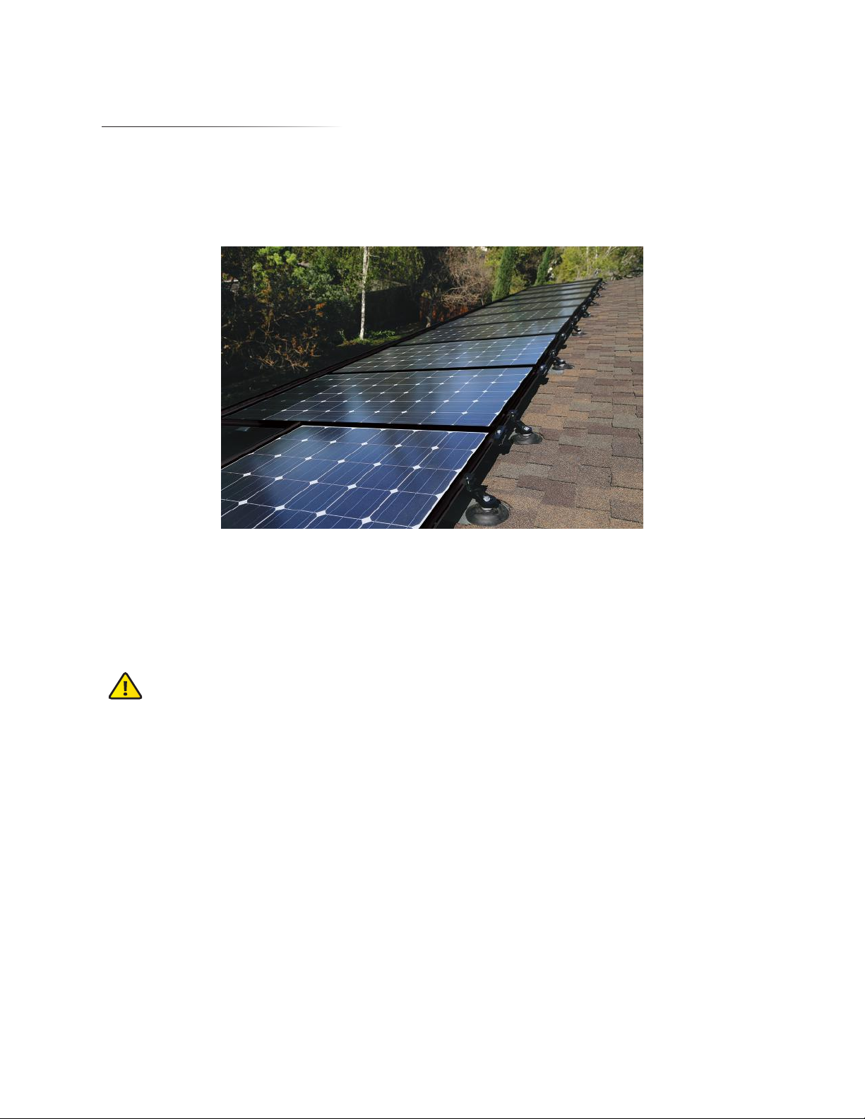
sunMAX™ by Ubiquiti Networks is a grid-tie solar solution that utilizes photovoltaic (PV) cells, or solar panels,
to convert solar energy into alternating current electricity. Using a watertight roof mounting system, sunMAX
offers both portrait and landscape array configurations with easy-to-use software to help you design and
implement a fully customizable solar solution.
The sunMAX solar solution should be deployed by an installer trained and familiar with the safety and
operational procedures of the sunMAX system and all of its components.
The AC Modules are UL listed to standard 1703 and the mounting hardware is UL listed to standard 2703.
Please adhere to all applicable codes, required permits, and regulations concerning the installation and
inspection requirements as they pertain to your location.
Safety
The following instructions and safety precautions are in place to ensure proper deployment and
operation of your solar equipment:
• Use only the materials and tools specified in this guide.
• Do not break or modify any of the solar components or use them outside of their intended use.
• Do not sit or stand on the surface of the AC Modules.
• Install components securely to avoid parts from becoming loose or falling off during the
installation.
• Only work in dry conditions with dry tools.
• Prevent rafters and sheathing from becoming wet.
• Install each AC Module securely to ensure proper operation and grounding of the array.
• AC Modules are installed on rooftops where there is danger of slipping or falling. Ladders and
scaffolding should be used when climbing onto roofs.
• Do not use chemicals on solar modules when cleaning.
• Do not wear metallic jewelry or any conductive material.
• Do not touch electrical contacts, cables, or wires.
1
Page 8

sunMAX™ Solar User Guide
Recommendations
Note: Become familiar with the installation site and its surroundings by visiting the location prior to
the actual install date.
Take the following precautions before starting work:
• Plan the job and visit the site before doing any work.
• Always work with at least one other person on site.
• Inspect power tools before using them.
When conditions make it necessary, tell workers to stop working.
• Do not perform installation in poor weather conditions such as rain, snow, ice, or high winds.
Wear appropriate work clothes and protective equipment.
• Wear gloves when handling sunMAX components. Flashing has sharp edges and will get hot when
exposed to sunlight.
• Work clothes for both the upper and lower body should fit well and allow you to move freely.
• Always wear protective equipment such as harnesses and lifelines.
• Wear non-slip shoes. Shoes get dirty when worn on a roof, so keep the soles clean.
Observe safety regulations for ascending and descending ladders and stepladders.
• Ladders from a first-story roof to a second-story roof are very dangerous. Do not set up a ladder on
a roof.
• When there is no other choice, straddle the ridge and lay down a rubber anchor mat, and secure
the ladder to the mat. Always have one person hold the ladder firmly.
• When you use a two-stage ladder, secure it with ropes or stays to prevent it from sliding sideways,
and have two people hold the ladder steady.
• Use ladders with steps broad enough to permit safe work.
When working in high places, wear harnesses and use scaffolding.
• When working at heights of 6' (1.83 m) or more, use scaffolds or other equipment to ensure a
stable work platform.
• Scaffolds should be designed and erected by a qualified person.
• When it is difficult to erect a stable work platform, install safety nets, wear harnesses, and take
other measures to prevent falls.
• Regulations mandate the use of harnesses. Fasten harnesses securely, and check that the length of
lifelines is 6' (1.83 m) or less.
• Attach the support line securely to a metal fixture installed for that purpose on a ridge or beam.
Install enclosures and covers to minimize risks.
• Install enclosures, guardrails, or covers at the end of work decks that are 10' (3.05 m) or more above
ground, at openings, and at other dangerous locations.
• When it is extremely difficult to install enclosures, guardrails, or covers, or when they must be
removed to work in that location, install a safety net, wear harnesses, and take other measures to
prevent falls.
2
Page 9

Chapter 1: Introduction
WARNING: Wiring work should be performed according to the provisions of the National Electrical
Code. Grounding work and wiring connections to the inverter should be performed by a qualified
electrician.
Please adhere to all applicable codes, required permits, and regulations concerning the installation and
inspection requirements as they pertain to your location. Pay special attention to Article 110, Chapter 2
Article 250, Chapter 3, Articles 300, 310, 480, and 690.
WARNING: The solar array generates electricity whenever it is exposed to sunlight. Be careful when
handling it. There is a danger of shock if you touch the connectors or wires of the electric cables.
Points to Check Before Wiring
• The solar modules generate electricity when exposed to light. You will need to wear insulating gloves.
• You will need a multimeter for volts, amps, resistance, and continuity capable of measuring DC and AC
up to 600V and 40A.
• Make sure your tools are insulated.
Wiring Solar Panels
• Never step or sit on the glass surface of the solar modules. The glass may break.
• When you install the solar modules on the mount, never allow an output cable to become caught
between the mount and a module frame.
• Ensure that the module connectors are fully inserted. There is a risk of malfunction if they are not
pushed all the way in.
• Support output cables to eliminate slack. High winds can blow slack cable against the mount, damaging
the cables.
Wiring Solar Arrays to the Inverter
• For wiring through walls, protect the cables with metal conduits, flexible metal conduits as permitted or
required by local and national electrical or building codes. Failure to do so can result in shock and short
circuits. Always use conduit to protect sections of array output cables that are exposed to sunlight.
• For wiring outdoors, protect cables with PVC conduits, metal conduits, or flexible conduits.
• Prevent water from entering or building up in conduit by using waterproof fittings or duct seal.
• To prevent shock, tape and label the cut ends of array output extension cables (the side opposite to
the connector side) before connecting to solar module output cables. Then, tape them again after
measuring the voltage of each array.
• To prevent shock when you connect the array output cables to the inverter, remove the tape one cable
at a time as you connect the cables.
Measuring Output Voltage
• Ensure that all solar modules are exposed to sunlight. (Remove lightproof sheets, if present.)
• Set the voltmeter measurement range to a DC voltage greater than -32VDC.
• Keep the plus (+) solar array output cables away from the ends of the minus (-) cables, as dangerous arcs
can occur. The array output voltage under normal conditions (clear skies) can be very high.
Grounding the Mount
• Use a proper ground wire according to your local safety regulations and requirements. For more
information, refer to “Grounding” on page 24 in this User Guide.
• Follow NEC 690 grounding provisions.
3
Page 10

sunMAX™ Solar User Guide
Installation Requirements
• No. 2 Phillips screwdriver
• Leveling string
• Tape measure
• Electric drill
• 3/16" (4.8 mm) long drill bit
• Chalk line
• Chalk stick (for cutting shingle)
• Tin snips or utility knife (for cutting shingle)
• 13 mm wrench (preferably an impact driver)
• Caulking gun
• EPDM-compatible roof caulking
• Shingle ripper or other prybar to remove existing nails
Additional Tile Roof Mount Requirements
• Angle grinder/saw with a masonry blade
• Roofing paper and roofing cement
• Felt paper
4
Page 11

Chapter 2: Components
Chapter 2: Components
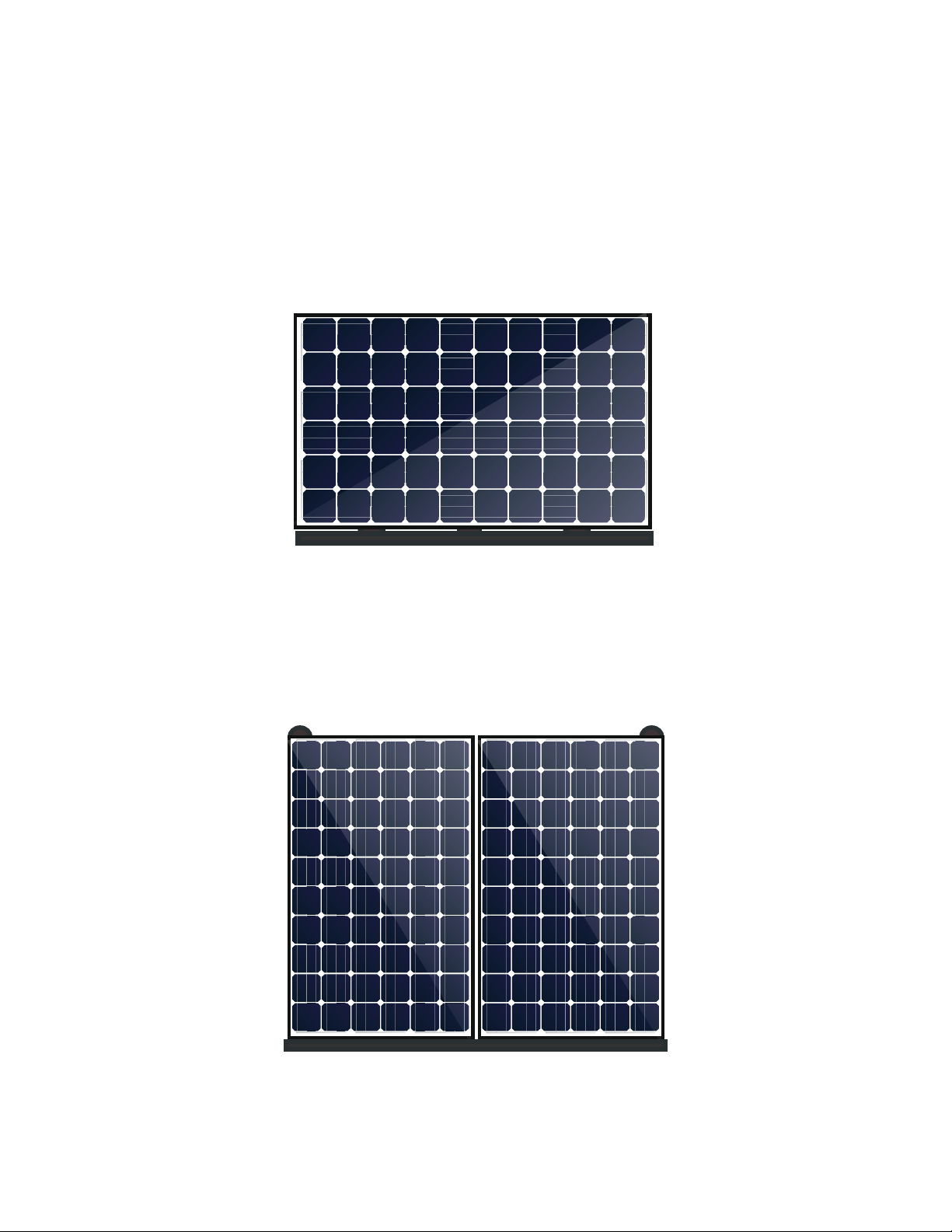
Solar Panel
The Solar Panel, model SM-SP-260W-DC, can be installed in portrait orientation, landscape orientation, or a
combination of both. Prior to transferring the Solar Panels to the roof for installation, each will be assembled
with cabling and a Microinverter. The assembled parts will be referred to as an ACModule. Each panel in the
array is installed downroof in the lower-edge position, side by side until a row is complete.
39.06” (992 mm)
64.92” (1649 mm)
Topside View of Solar Panel
(Portrait Orientation)
Underside View of Solar Panel
(Portrait Orientation)
(Landscape Orientation)
Panel Connector
Panel Connectors, model SM-PC-10, join solar panels together structurally between adjacent corners and
along the outside edges of the Solar Panels and bond them together electrically. The arrow located on the
top surface of each Panel Connector should always point downward towards the Trim Cover.
5
Page 12

sunMAX™ Solar User Guide
Mounting Assembly
Mounting Assemblies, model SM-MA-10, provide structural support and 360° adjustment swivel between
the Roof Mount and outer edges of the Solar Panel. The arrow located on the top surface of each Mounting
Assembly should always point downward towards the Trim Cover.
Connector Mount
Connector Mounts, model SM-CM-10, provide structural support and 360° adjustment between the Roof
Mount and outer edges of the Solar Panel where Mount Assemblies would coincide with a Panel Connector
location. Each Connector Mount has an arrow on the top surface of the 360° swivel that should always face
forward toward the Trim Cover.
6
Page 13
Chapter 2: Components
Trim Cover Kit
The Trim Cover Kit is used to enhance the visual appearance and aesthetics along the entire front edge of the
array and help ease installation of the panels. There are three versions of the Trim Cover Kit: 1-panel portrait
(SM-TC-1P-5), 2-panel portrait (SM-TC-2P-5), and landscape (SM-TC-L-5).
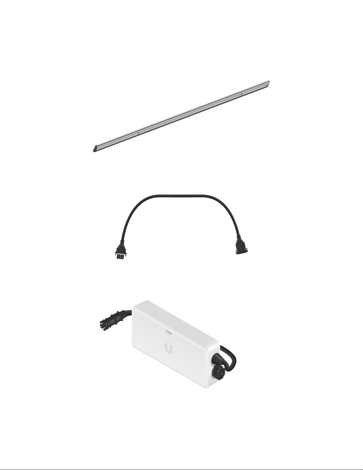
Jumper Cable
Jumper Cables, model SM-JC-4C-5, connect and extend the Y-Cables in adjacent rows together underneath
the solar array. Jumper Cables attach to the inside edge of the Solar Panels using Cable Support Clips.
Solar Gateway
The Solar Gateway, model SM-SG, communicates with and gathers data from all Microinverters in the solar
array and sends information to the Ubiquiti® sunMAX cloud management system via the local area network.
7
Page 14
sunMAX™ Solar User Guide
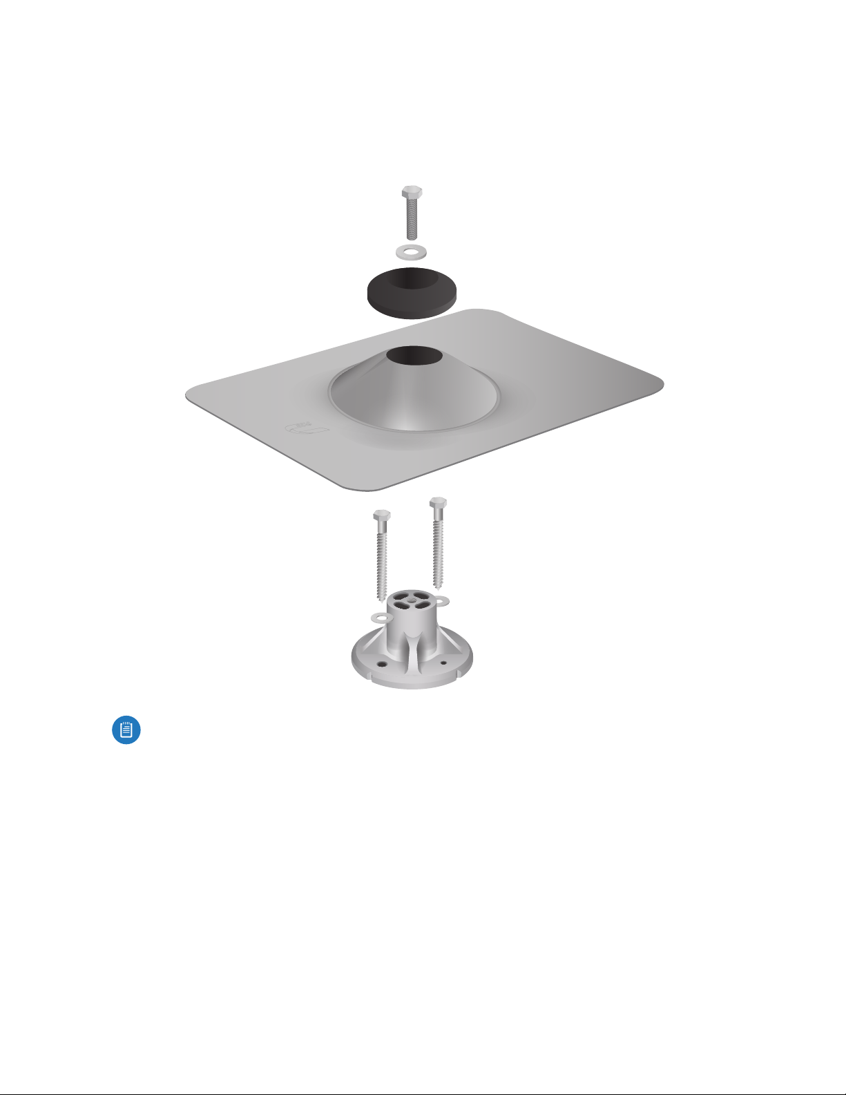
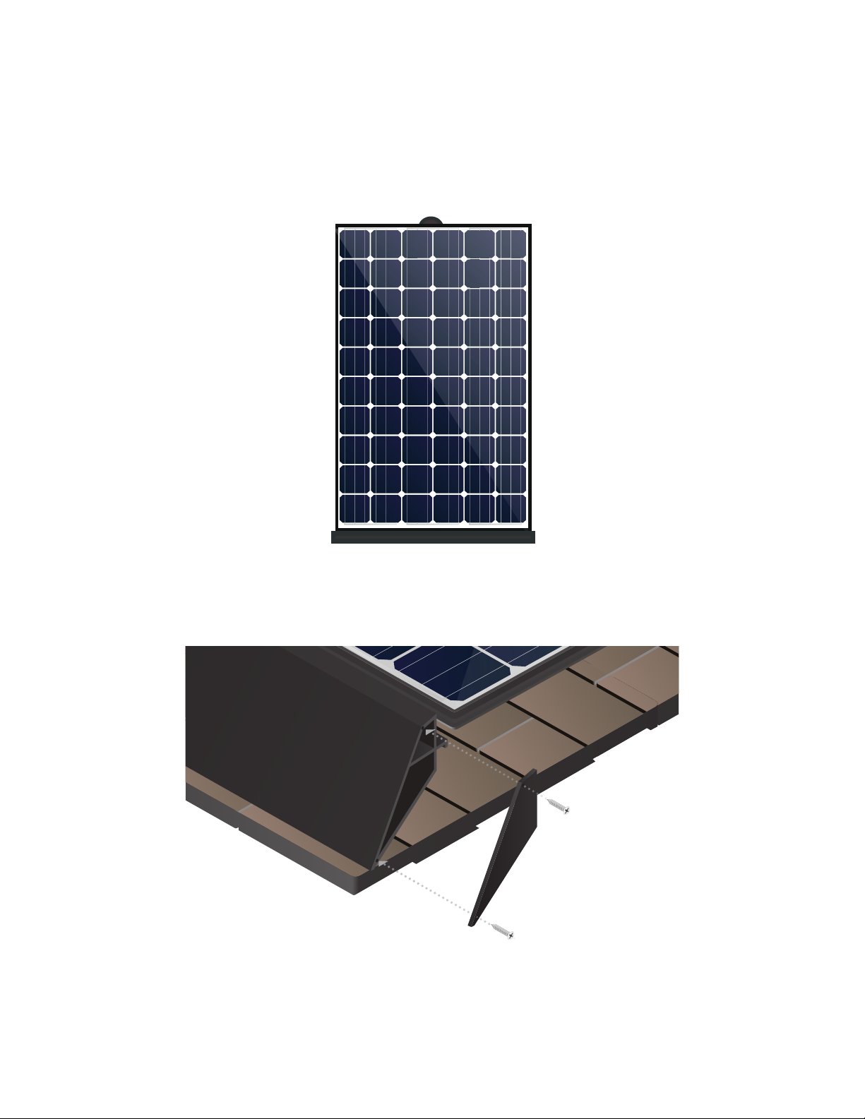
Roof Mount Kit
The Roof Mount Kit, model SM-RM-C-10, provides a structural mount between the roof surface and Mounting
Assembly to support the array. The kit includes the roof mount and mounting hardware, roof flashing, and
counter flashing to ensure a watertight installation.
Note: The Flashing has sharp edges and will get hot when exposed to sunlight.
8
Page 15
Chapter 2: Components
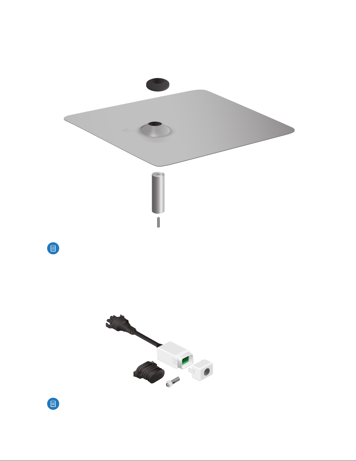
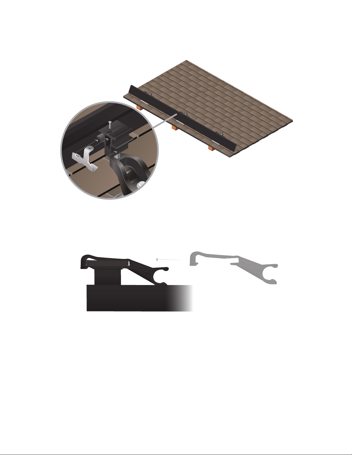
Tile Accessory Kit
Used in conjunction with the Roof Mount Kit, the Tile Accessory Kit, model SM-RM-T-10, includes additional
components required for tile-roof mounting: a threaded stud, extension post, upper aluminum Flashing, and
counter flashing. The upper aluminum Flashing is flexible and can be formed to fit most flat or curved tiles.
Note: The Flashing has sharp edges and will get hot when exposed to sunlight.
End Run
The End Run, model SM-EC-NA, provides easy adaptation of cabling from the array to the electrical panel
feeding the grid. It connects the open-ended Y-cable in your solar array to the house-side wiring that feeds
into the electrical panel of your building. The End Run is part of a kit and includes the End Run, a cabling end
cap, and grounding stud with nut.
Note: Install the Solar Panels so that the End Run will terminate near the breaker box or closest to
the location where the house-side wiring will penetrate the roof.
9
Page 16
sunMAX™ Solar User Guide
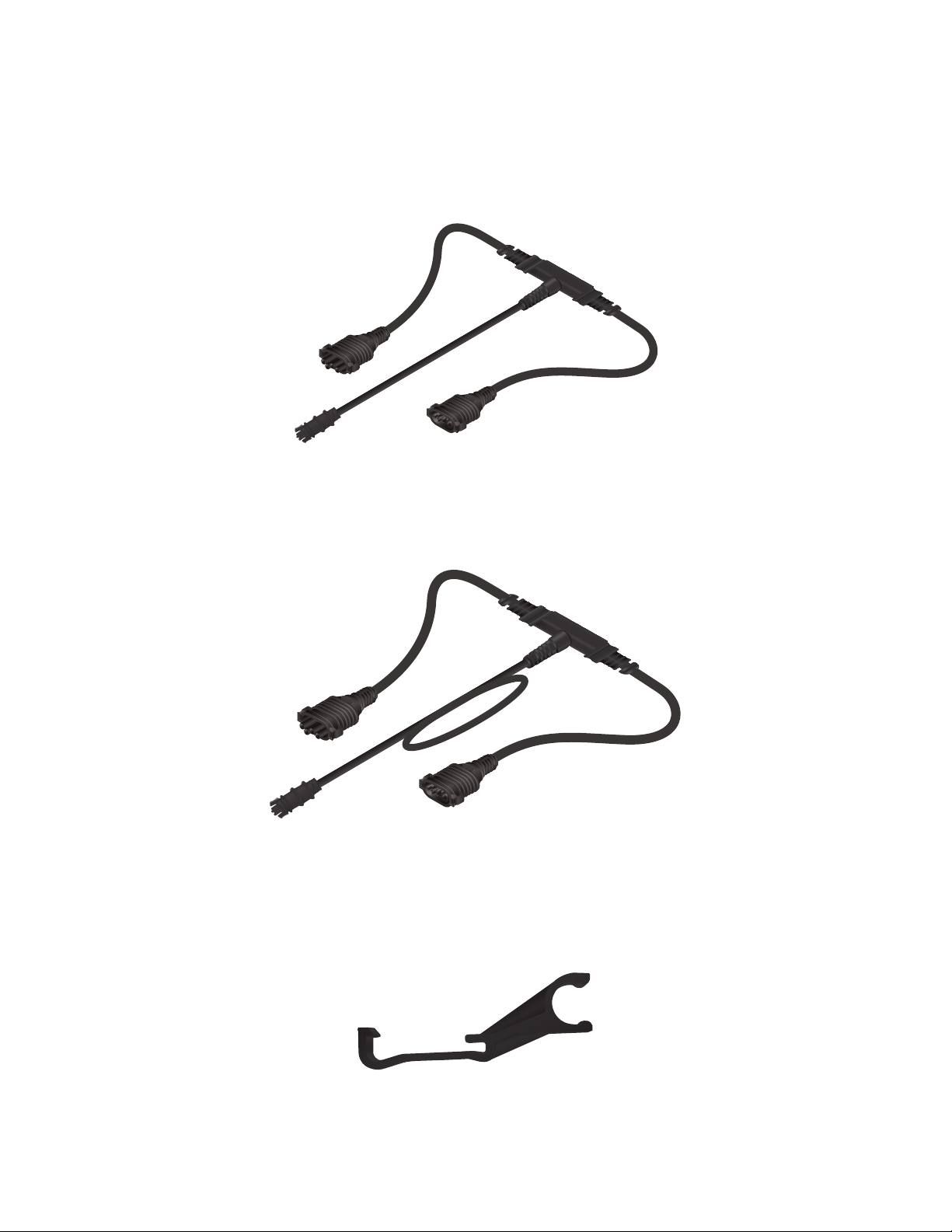
Y-Cables
Portrait
The Portrait Y-Cables, model SM-YC-P4-5, are used to connect panels and devices, such as the Solar Gateway
or Microinverter, in a portrait-array configuration.
Landscape
The Landscape Y-Cables, model SM-YC-L4-5, are used to connect panels and devices, such as the Solar
Gateway or a Microinverter, in a landscape-array configuration.
Cable Support Clips
The Cable Support Clips, model SM-CC-50, slide onto the inner frame underneath the Solar Panel and pivot
down over the outer edge of the frame. Cable Support Clips support Jumper Cables and Y-Cables along the
inside edges of the Solar Panels.
10
Page 17

Chapter 3: Component Usage
Chapter 3: Component Usage
All sunMAX mounting components are installed into frame of the Solar Panel using the same motion.
Components hook underneath the outer edge of the panel’s frame and then pivot down. Never force a
component into place as it can damage the frame of the Solar Panel.
Panel Connectors
Panel Connectors, model SM-PC-10, join Solar Panels together structurally between adjacent corners and
along the outside edges of the Solar Panels and bond them together electrically. The arrow located on the
top surface of each Panel Connector should always point downward towards the Trim Cover. Do not install
vertically between the panels in your array.
If a Mounting Assembly is near a Panel Connector location, install the Panel Connector first, then install the
Mounting Assembly.
11
Page 18

sunMAX™ Solar User Guide
Panel Connectors have preset gaps on them where the Solar Panels will fit in as they come together during
the installation. Align the preset gaps with the edge of the Solar Panel before hooking the Panel Connector
underneath the frame and pivoting down.
Mounting Assembly
Mounting Assemblies provide structural support and 360˚ adjustment between the Roof Mount and the outer
edges of the Solar Panel. The Mounting Assembly base also slides forward and backward to allow adjustment
of the swivel mount position. The arrow located on the top surface of each Mounting Assembly should always
point downward towards the Trim Cover.
Connector Mounts
The same function and installation rules apply to the Connector Mounts as well. Connector Mounts, model
SM‑CM‑10, provide structural support and 360˚ adjustment between the Roof Mount and outer edges of the
array where Mounting Assemblies would coincide with a Panel Connector location.
12
Page 19
Chapter 3: Component Usage
Trim Cover Kit
The Trim Cover Kit serves as an assembly aid for alignment and maintains the Class A fire rating when
installed. There should always be at least one Mounting Assembly and one Panel Connector per Trim Cover.
There are three different Trim Covers available for use depending on the design and orientation of your array:
Landscape, 2-Panel Portrait, and 1-Panel Portrait.
Landscape
In landscape layout, there will be one landscape Trim Cover per column. The standard width of one landscape
Trim Cover is the same width as one Solar Panel in landscape orientation.
2-Panel Portrait
The 2-Panel Portait Trim Cover is the standard width of two Solar Panels in portrait orientation. For every two
columns of Solar Panels in portrait layout, there will be one Trim Cover that extends along the front row of
both panels. For example, in an eight-column array of portrait Solar Panels, use four of the SM-TC-2P-5 Trim
Covers.
13
Page 20
sunMAX™ Solar User Guide
1-Panel Portrait
The 1-Panel Portrait Trim Cover is used in a solar array where there are an odd number of portrait columns.
For example, in an array of three portrait columns, use one 2-Panel Portrait Trim Cover and one 1-Panel
Portrait Trim Cover. The 1-Panel Portait Trim Cover is the standard width of a single Solar Panel in portrait
orientation.
The Trim Covers also come with two end plates. Most solar arrays use multiple Trim Covers side by side across
the front edge of the array. Once the front edge of your solar array is complete, install an end plate on both
ends of the Trim Cover using the included mounting screws.
14
Page 21
Chapter 3: Component Usage
Each Trim Cover also comes with a set of trim locks to secure it in place at all Mounting Assembly locations
along the front edge of the array.
Cable Support Clips
The Cable Support Clips slide onto the inner frame underneath the Solar Panel and pivot down over the outer
edge of the frame. Cable Support Clips support Jumper Cables and Y-Cables along the inside edges of the
Solar Panels.
15
Page 22

sunMAX™ Solar User Guide
Flashing
Flashing is placed over each roof mount and helps ensure a watertight installation when positioned properly.
The upper edge of the Flashing should always be covered by the third course of shingles to prevent water
from entering underneath the Flashing. The upper edge of the Flashing should be covered by at least ¼"
(6mm) of the third course of shingles. The lower edge of the Flashing should not extend beyond the edge
line of the first course of shingles.
Third Course
Second Course
First Course
Incorrect
Flashing is exposed and does
not sit underneath the third
course of shingles.
Incorrect
Flashing should not hang over
the edge of the first course of
shingles.
Correct
Flashing reaches past the second
course of shingles and is positioned
underneath the third course.
Correct
Flashing is positioned just above the
first row of shingles where the roof
mount was installed.
Correct
The second course of shingles have been
trimmed around the flashing to position
it higher underneath the third course.
Remove any nails that
interfere with the proper
placement of flashing on
the roof’s surface.
Correct
Flashing is positioned above the
first row of shingles where the roof
mount was installed.
Jumper Cables
Jumper Cables, model SM-JC-4C-5, have a male connector and a female connector, one on each end. Each
Jumper Cable attaches to the inside edge underneath the AC Modules using Cable Support Clips.
Jumper Cables are used to connect adjacent rows of AC Modules together within a single array. In a multi-row
system, Y-Cables alternate their orientation, ending with a male or female connector every other row.
16
Page 23

Chapter 3: Component Usage
Y-Cables
Y-Cables run along the inside edges of AC Modules to allow access to the cable ends during installation.
Y-Cables come in both portrait and landscape configuration depending on how the AC Modules will be
installed in the array. Y-Cables are reversible and can be installed with a male or female connector on either
side of the module. This allows the End Run to be installed at a preferred location within the array.
Typically, the End Run is installed closest to the main breaker panel or location where the wiring feed will
penetrate the roof. Since the End Run has a female connector, it should terminate on a row that ends with a
male connector.
17
Page 24

sunMAX™ Solar User Guide
Here are a few examples:
Example 1
Looking top-side down, if you want the End Run to terminate on the right side of row two in the array, ensure
that the Y-Cable coming from the last AC Module in that row has a male connector on it.
End Run connecting to
male connector on Y-Cable
Row 2
Jumper Cable (underneath)
connecting two rows together
Female connector on Jumper Cable
Male connector on Y-Cable
Row 1
Example 1
Cable end cap terminating
female connector on Y-Cable
Example 2
Looking top-side down, if you want the End Run to terminate on the right side of row one in the array, ensure
that the Y-Cable coming from the last AC Module in that row has a male connector on it.
Cable end cap terminating
female connector on Y-Cable
Row 2
Jumper Cable (underneath)
connecting two rows together
Male connector on Jumper Cable
18
Female connector on Y-Cable
Row 1
End Run connecting to
male connector on Y-Cable
Example 2
Page 25

Chapter 3: Component Usage
Example 3
Looking top-side down, if you want the End Run to terminate on the left side of row two in the array, ensure
that the Y-Cable coming from the last AC Module in that row has a male connector on it.
End Run connecting to
male connector on Y-Cable
Row 2
Jumper Cable (underneath)
connecting two rows together
Female connector on Jumper Cable
Male connector on Y-Cable
Cable end cap terminating
female connector on Y-Cable
Row 1
Example 3
If the End Run terminates at the end of a row with a female connector on it, you have two options:
1. Move the End Run location to the next row in the array, which ends with a male connector on it.
2. Reverse the orientation of the Y-Cable in the current row by performing the following steps:
a. Remove the Y-Cable from the Cable Support Clips.
b. Turn the Y-Cable over to reverse the male and female connectors.
c. Re-attach the Y-Cable to the Cable Support Clips.
Female Connector
Cable Support Clips
Remove Y-Cable from
Cable Support Clips
Male Connector Female ConnectorMale Connector
Cable Support Clips
Re-attach Y-Cable to
Cable Support Clips
Step a
Step b
Step c
19
Page 26

sunMAX™ Solar User Guide
Solar Panel
When installing a single Solar Panel, either portrait or landscape, it must have a minimum of four Mounting
Assemblies. The overhang distance past each mount (on both sides) and the spacing between Mounting
Assemblies must still adhere to the same specifications as a multi-panel array. For grounding purposes, a
Panel Connector, along with the appropriate grounding wire, is installed between the Trim Cover and the
lower edge of the solar array.
Sample Layout Configurations
The following illustrations show proper placement of Panel Connectors and Roof Mounts based on the
configuration layout of your solar array.
Panel Connector Roof Mount
Rectangle Shape (Landscape)
Staggered Rows
20
Page 27

Transitioning from Landscape to Portrait
Transitioning from Portrait to Landscape
Chapter 3: Component Usage
Pyramid Shape
21
Page 28

sunMAX™ Solar User Guide
Additional Layout Configurations
Panel Connector Roof Mount
Landscape Array Omitting Center AC Module (for Roofing Vent or Pipe)
Rectangle Shape (Portrait)
22
Page 29
Chapter 4: Analysis
Chapter 4: Analysis
To determine the maximum amount of spacing when installing your solar system, consider the location and
general weather conditions surrounding your install. Refer to the span tables in “Appendix A: Span Tables”
on page 57 to determine the recommended measurements as they pertain to your location.
Snow Loading
To determine the ground snow load at the installation site, consult with your local building and safety
department for the specific requirements for your location. AC Modules should not be installed in snowdrift
areas of the roof.
Basic Wind Speed
Determine the wind speed at your installation site and consult your local building and safety department for
guidelines.
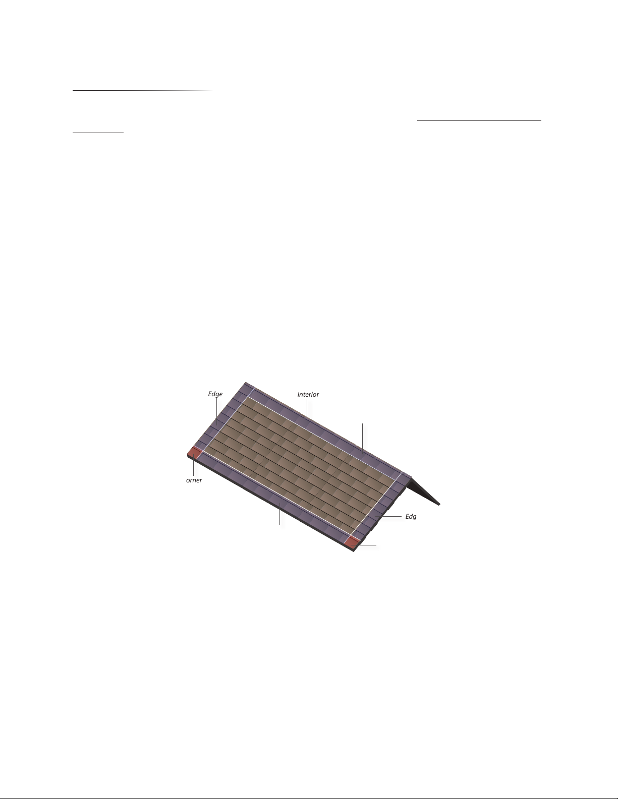
Roof Zones
Locate the area on the roof where you will be installing the solar array. The roof is divided into three zones:
the interior, edges, and corners.
• Interior The innermost area surrounded by the edges, also referred to as the field.
• Edges The edges are defined as 10% of the least horizontal dimension or a minimum of 3' (0.9 m) from
the edge of the roof and represent areas of higher wind load.
• Corners The corners are defined as the intersection of two edge zones on the leading edge of the roof.
Wind loads are highest in the corner zones and lowest in the interior zone. AC Modules should not be
mounted in the corner zones.
Edge
Corner
Interior
Edge
Edge
Edge
Corner
Exposure Category
Determine the exposure category of the installation site by using the following guidelines:
• Category B Urban, suburban, wooded areas or other terrain with numerous obstructions or closely
placed objects having the size of single-family dwellings or larger.
• Category C Open terrain with scattered obstructions such as flat open country, grasslands, or
shorelines in hurricane-prone regions.
• Category D Flat, unobstructed areas within 1500' (460 m) of shoreline or areas exposed to wind
flowing over open water (excluding shorelines of hurricane-prone regions) for a distance of at least
onemile (1.6 km).
23
Page 30

sunMAX™ Solar User Guide
Grounding
The sunMAX mounting system provides a built-in integrated grounding system to bond the array together.
When Panel Connectors are installed they provide up to a four-way bond with adjacent modules and/or trim
skirts. By bonding modules into one contiguous system, only a single grounding wire is required for an array
up to 60 panels. The grounding wire connects to any one of the Panel Connectors in the solar system and
terminates near the conduit where the house wiring penetrates the roof.
Special Mounting Considerations
Mounting specifications are based on conditions where:
• The building is not a special-occupancy structure that represents a substantial hazard to human life.
• The building is not an essential facility such as a public school or hospital.
• The building is not located on a bluff or near the top of a hill where topographic effects change.
If your installation site differs from any of the factors above, please consult with Ubiquiti Networks at
sunlink.ubnt.com about your particular solar project.
Maximum Cantilever
The other important factor when mounting AC Modules is the maximum cantilever distance that it can
overhang past the outer Mounting Assembly. For portrait AC Modules, the maximum distance is 15.75"
(400 mm) and for landscape AC Modules, the maximum distance is 19.69" (500 mm). If necessary, shift the
ACModule or mount location to reduce the cantilever distance. For configurations with staggered rows of
AC Modules, check the cantilever distance on each row.
15.75" (400 mm) for portrait
19.69" (500 mm) for landscape
Thermal Expansion
Arrays more than 33' (10 m) long in any direction should be separated by a minimum of 1" (25 mm) gap to
allow for thermal expansion. This will help prevent damage to the module. Gaps should be located near the
center of the array and each array should be grounded individually.
24
Page 31

Chapter 5: AC Module Assembly
Chapter 5: AC Module Assembly
The AC Module is a Solar Panel with a Microinverter installed. For ease of installation, assemble the ACModule
and attach the required cabling and support clips prior to transferring the AC Module to the roof.
Y-Cable
Microinverter
Solar Panel
AC Module
Installing the Microinverter
1. Stand the Solar Panel up against a sturdy wall or lay it on a flat surface that will not scratch the top side of
the panel. The pre-installed junction box should be facing you on the upper half of the Solar Panel.
Note: Do not sit or place heavy objects anywhere on the Solar Panel.
2. Position the Microinverter into the Solar Panel and slide it up along the edge of the frame until the holes
line up at the top. Ensure that the neighboring side of the frame edge sits in the slotted edge of the
Microinverter, which secures it to the frame.
Junction Box
DC Cables
25
Page 32

sunMAX™ Solar User Guide
3. Using the mounting bolts, secure the Microinverter to the inside edge of the Solar Panel using 9 lb-ft or
12N‑m of torque. Ensure that the neighboring edge of the Microinverter is still attached to the corner
frame edge before inserting the mounting bolts.
4. Connect both cables on the junction box to the DC ports on the Microinverter until you hear them snap in.
Each connector is uniquely shaped to prevent reversal during the installation. The Solar Panel will now be
referred to as an AC Module.
Installing the Cable Support Clips and Y-Cable
Before attaching Cable Support Clips and Y-Cables to the AC Module, decide whether your solar array will be
configured for portrait or landscape orientation.
• Portrait AC Modules require two Cable Support Clips and a Y-Cable, model SM-YC-P4.
• Landscape AC Modules require three Cable Support Clips and a Y-Cable, model SM-YC-L4.
26
Page 33

Chapter 5: AC Module Assembly
Portrait Orientation
1. Stand the AC Module up vertically against a wall so that the Microinverter is in the upper-right corner as
you face the underside surface of the panel.
2. Attach the Cable Support Clips to the AC Module by performing the following steps:
a. Slide the first Cable Support Clip onto the inside edge of the frame, halfway between the Microinverter
and junction box.
b. Using your thumb, press the top of the Cable Support Clip over the front edge of the frame until it
snaps into place.
c. Slide the second Cable Support Clip onto the inside edge of the frame, halfway between the junction
box and the left corner edge of the AC Module.
Note: Position the Cable Support Clips along the edges of the AC Module so that the Y-Cables
and Jumper Cables do not sag during installation.
3. Attach the Y-Cable to the Cable Support Clips, securing it to the inside edge of the AC Module.
27
Page 34

sunMAX™ Solar User Guide
Landscape Orientation
1. Stand the AC Module up horizontally against a wall so that the Microinverter is in the upper-left corner as
you face the underside surface of the panel.
2. Attach the Cable Support Clips to the AC Module by performing the following steps:
a. Slide the first Cable Support Clip onto the inside edge of the frame, approximately 12" (305 mm) from
the right corner edge of the AC Module.
b. Using your thumb, press the top of the Cable Support Clip over the front edge of the frame until it
snaps into place.
c. Slide the second Cable Support Clip onto the inside edge of the frame, approximately 12" (305 mm)
from the first Cable Support Clip.
d. Slide the third Cable Support Clip onto the inside edge of the frame, approximately 12" (305 mm) from
the left corner edge of the AC Module.
3. Attach the Y-Cable to the Cable Support Clips, securing it to the inside edge of the AC Module.
28
Page 35

Chapter 5: AC Module Assembly
Connecting Y-Cable to Microinverter
1. Using the AC Disconnect Tool, remove the Protective Cap from the Power Connector on the Y-Cable.
AC Disconnect Tool
Protective Cap
Power Connector
2. Plug the Power Connector on the Y-Cable into the AC Port on the Microinverter. The Power Connector is
keyed to fit one way into the Microinverter.
Power Connector (Y-Cable)
AC Port (Microinverter)
29
Page 36

sunMAX™ Solar User Guide
The AC Module is now complete and ready for installation.
Portrait Configuration
Landscape Configiuration
30
Page 37

Chapter 6: Installation
Chapter 6: Installation
Roof Mount and Flashing Installation
Locate on the roof where the solar array will be installed. Ensure that you adhere to all local rules and
regulations that correspond to your location in regards to measurements and spacing from roof eaves and
ridges. For tile roof installations, refer to “Appendix B: Tile Roof” on page 63.
1. Mark the location of the first row of Roof Mounts by placing a chalk line horizontally across the roof. This
chalk line should be 1.5" (38mm) up from where the lower edge of the solar array will be installed.
2. Mark the location of the second row of Roof Mounts by placing a parallel chalk line above the first, using
the following guidelines:
• For portrait configurations, mark 66" (1675 mm) up from the previous chalk line.
• For landscape configurations, mark 40.13" (1020 mm) up from the previous chalk line.
For additional rows, repeat this step as needed.
40 and 1/8" (1020 mm) Landscape
66" (1675 mm) Portrait
3. Mark the center line of each rafter along each of the horizontal chalk lines. These marks should be within
0.25" (6 mm) of the rafter center line.
31
Page 38

sunMAX™ Solar User Guide
4. Identify the first mount location by locating the closest rafter underneath the outside edge of the first
ACModule in your array. Mark the center of the first rafter that will support the lower-edge corner of the
first AC Module in your array. Ensure the location does not exceed the maximum cantilever distance of
15.75" (400mm) for portrait configuration or 19.69" (500 mm) for landscape configuration. If a rafter
does not fall within the maximum cantilever distance based on the current chalk line position, shift the
ACModule position inward to reduce the distance.
15.75" (400 mm) for portrait
19.69" (500 mm) for landscape
5. Once the first roof mount location is marked, continue to mark additional roof mount locations along
each horizontal chalk line, observing the maximum spacing for your location until the desired layout is
complete. Check the opposite end of the array to ensure the cantilever distance has not been exceeded at
any other locations as well.
Refer to “Appendix A: Span Tables” on page 57 to determine the mount spacing for your particular
installation location. This will provide you with the maximum spacing for your roof mounts.
6. Once you’ve determined the proper spacing, place each roof mount in position over the chalk lines. This
will mark the mount locations and let you know which shingles to cut.
32
Page 39

Chapter 6: Installation
7. The roof shingles need to be cut to allow proper installation of the Roof Mounts and Flashing. Use a chalk
stick to mark a 3" (75mm) area around the roof mount (to use as a guide) and trim the second course of
shingles.
8. Once you’ve trimmed the shingles, position the Roof Mount over the rafter center and start predrilling
the two holes that will be used to secure the roof mount to the rafter. Use the shingle cutout and the two
smaller holes on the roof mount as a guide for positioning.
Note: To avoid damaging the roof mount, do not drill the holes completely through with the roof
mount in place.
9. Remove the roof mount temporarily and finish predrilling two 3/16" (4.8 mm) holes approximately 2"
(50mm) deep.
33
Page 40

sunMAX™ Solar User Guide
10. Cover both hole openings with roofing sealant. This will ensure a watertight installation once you’ve
secured the lag screws to the rafter.
11. Position the Roof Mount into place and tighten the lag screws until the Roof Mount is secure.
12. Slide a roofing bar under the shingles to break the bond where the Flashing will sit. Remove any nails that
will interfere with the installation of Flashing and lift up the shingles.
34
Page 41

Chapter 6: Installation
13. Apply roof sealant to the underside of the Flashing and in an inverted U shape around the opening.
Wearing gloves is recommended as the Flashing has sharp edges and also may become hot
when exposed to warm temperatures.
14. Slip the Flashing into place underneath the upper course of shingles and lower it over the roof mount. The
Flashing should be installed with the Ubiquiti logo towards the front.
15. Reseat the shingles to cover the Flashing. Position the Flashing to meet the following criteria:
• The lower edge does not extend beyond the first course of shingles.
• The upper edge is located underneath the third course of shingles.
35
Page 42

sunMAX™ Solar User Guide
16. Apply a minimum of ¼" (6 mm) continuous roof caulking around the gap between the Flashing and the
Roof Mount.
17. Install the rubber counter flashing over the neck of the Roof Mount until it is fully seated onto the Flashing.
Mounting Assembly Installation
1. Use the mounting hardware to attach Mounting Assemblies to the Roof Mounts. To begin, only install
Mounting Assemblies at the two outer locations in the front row of the array. Each Mounting Assembly has
an arrow on the top surface of the 360° swivel that should always point towards the Trim Cover.
36
Page 43

Chapter 6: Installation
2. Secure and tighten each mounting assembly bolt using 14 lb-ft or 19 N-m of torque. The mounting base
and swivel portion for each Mounting Assembly should be facing downroof as shown.
Note: If you need to adjust the position of the Mounting Assemblies later, you can loosen the
mounting bolts and make the necessary adjustments.
Leveling the Mounting Assemblies
1. Using leveling string, tie a knot around the first mounting assembly stud, just below the swivel portion
of the Mounting Assembly. Ensure that the top portion of the stud can be seen through the opening of
the mount swivel. As a starting point, adjust the Mounting Assembly to mid-height where the top of the
mounting stud is level with the lower lip of the mount swivel.
Mount Swivel
Mounting Assembly Stud
Leveling String (Knot)
2. Pull the leveling string up and over the top of the mount swivel, extending it all the way to the last
Mounting Assembly in the row.
37
Page 44

sunMAX™ Solar User Guide
3. Once you’ve reached the Mounting Assembly at the other end of the row, pull the leveling string over the
top surface of the mount swivel and tie another knot around the mounting assembly stud as performed
in step 1.
Note: Apply some tension to the string to create a leveling guide between the first and last
Mounting Assemblies.
4. At both ends of the leveling guide, measure the height between the string and the surface of the roof
structure. If the height is not the same at both ends, turn the mount swivel to adjust the height so they
are the same. To raise the height, turn the mount swivel counterclockwise. To lower the height, turn the
mount swivel clockwise.
5. Once the first and last Mounting Assemblies in that row are the same height, adjust the remaining
Mounting Assemblies by turning the mount swivels (clockwise or counterclockwise) until they are the
same height and position as the leveling string.
6. Secure and tighten each Mounting Assembly bolt using 14 lb-ft or 19 N-m of torque and remove the
leveling string before installing the Trim Cover.
38
Page 45

Chapter 6: Installation
Trim Cover Installation
With all of the Mounting Assemblies now at the same height, install the trim cover by following these steps:
1. Hook the Trim Cover over the top lip of the Mounting Assemblies by placing it horizontally across the
mount swivels in row one and rotating it down until it comes to a stop.
2. The trim covers are sized to fit the AC Module edges and should be positioned to support each location
in which the AC Modules will be installed. Ensure that each Trim Cover is fully seated on the Mounting
Assemblies in that row. If more than one Trim Cover will be installed, position each additional one side by
side until the front row is complete.
3. Using the included hardware, attach the endcap plates to both of the open ends of the Trim Cover. Align
the holes in the endcap plate with the pre-drilled holes on the ends of the Trim Cover and secure it to each
of the sides.
39
Page 46

sunMAX™ Solar User Guide
Trim Lock Installation
Once the Trim Covers are installed, secure each Trim Cover to the Mounting Assemblies by installing a trim lock
on each mounting swivel.
1. Place and hold the trim lock up against the side of the Mounting Assembly and align it underneath the
hole located in the mounting swivel.
2. Holding the trim lock in place, insert the trim lock screw through the top of the Mounting Assembly and
secure the trim lock to the mount swivel. The trim lock will also secure the Trim Cover to the Mounting
Assemblies in row one.
Panel Connector Installation for Trim Cover
Prior to installing the first row of AC Modules, insert Panel Connectors into the Trim Cover at all locations where
AC Modules will be installed. If the first row in your solar array will consist of more than one Trim Cover, you
will also use a Panel Connector to join together the ends of adjoining Trim Covers.
Each Panel Connector has an arrow on the top surface that should point toward the Trim Cover. To help with
alignment, the arrow on the Panel Connector should be aligned with one of the following:
• The alignment mark on all 2-Panel Portrait Trim Covers.
40
Page 47

Chapter 6: Installation
• The vertical gap created by the installation of two Trim Covers installed side by side.
AC Module Installation
With the Trim Covers installed properly, follow these steps to install the ACModules:
1. Hook the AC Module onto the top lip of the Mounting Assemblies in row one and lower it approximately
45˚ while pulling back slightly on the AC Module.
Note: The remaining roof mount locations should not have Mounting Assemblies installed yet.
AC Module
Trim Cover
Mounting Assembly
2. Holding the AC Module at a 45˚ angle, hook the Mounting Assembly into the edge of the frame, ensuring
the arrow is facing forward. Line up the mounting base over the Roof Mount as you lower the AC Module.
Note: If the ACModule will sit on more than one Mounting Assembly or Connector Mount, ensure
that each component is inserted into the top edge of the AC Module before securing it to the
roof mounts.
41
Page 48
sunMAX™ Solar User Guide
3. While lowering the AC Module into place, continue to pull it slightly towards you to ensure it remains
hooked onto the swivel mounts in the previous row. Secure the AC Module to the Roof Mounts using the
Mounting Assembly. If the AC Module is not seated properly or sitting evenly with the mounting hardware
in row one, make the necessary adjustments.
Mounting Assembly Base
AC Module
Note: If adjustments need to be made to one or both of the Mounting Assemblies in row two,
turn the base of the Mounting Assembly in either direction to adjust its height. To raise the
height, turn the base clockwise. To lower the height, turn the base counterclockwise.
4. Once the Mounting Assemblies are all the same height, secure the AC Module to the Roof Mount.
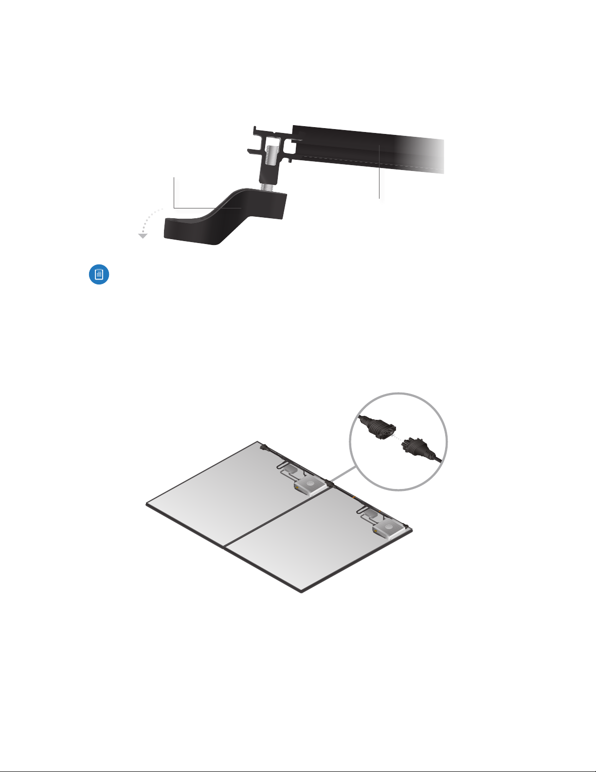
5. Install the second AC Module, like the first, and join them together with a panel connector along the frame
corners.
6. For each additional AC Module in the array, connect the AC trunk cables underneath before securing
the next AC Module to the Roof Mounts. This ensures easier accessibility to the assembly components
underneath.
42
Page 49

Chapter 6: Installation
7. Once the trunk cables are connected, lower and secure the ACModule into place.
8. If the corner edges of the AC Modules do not rest on a Connector Mount, use a Panel Connector to join the
AC Modules together. Panel Connectors connect AC Modules together structurally along the frame edges
and bond them together electrically.
9. Continue installing AC Modules, working from side to side, until the layout of your solar array is complete.
In a multi-row system, Jumper Cables are required to connect the second row of AC Modules to the first.
43
Page 50

sunMAX™ Solar User Guide
Solar Gateway
Ports
Reset Button
Ethernet Port
Ethernet Port This Ethernet port is used to connect the Solar Gateway to your LAN.
Reset Button This button resets the Solar Gateway back to factory defaults. Press and hold the Reset button
for more than 10 seconds while the Solar Gateway is powered on.
LEDs and Connectors
Power LED
Network Activity LED
Inverter Activity LED
Input
(from Microinverter)
Output
(to ACtrunk cable)
LEDs
Power The Power LED will light steady green when the device is connected to a power source. The LED
may change color during general system activity.
Network Activity The Network Activity LED will light steady green when the network and cloud are
connected. It will light red if a network connection cannot be established
Inverter Activity The Inverter Activity LED will light steady green when all Microinverters are detected.
It will light yellow if one or more of the Microinverters are missing and light red if errors are detected.
Connectors
The Solar Gateway has two external connectors.
Input Connects the Solar Gateway to the Microinverter.
Output Connects the AC cable to the Solar Gateway.
44
Page 51

Chapter 6: Installation
Installation
WARNING: Before installing this product, disconnect the solar system from the grid or any source of
power to prevent shock or damage.
1. Tilt the Solar Gateway forward and hook it underneath the upper edge of the solar module railing. Rotate
it down until it stops and rests along the side of the AC Module.
2. Use the AC Disconnect Tool to disconnect the AC trunk cable from the Microinverter.
3. Connect the AC trunk cable to the Output connector on the Solar Gateway.
45
Page 52

sunMAX™ Solar User Guide
4. Connect the Input cable on the Solar Gateway to the four-prong connector on the Microinverter.
Setup
The sunMAX Install app allows you to set up the Solar Gateway on your network to communicate with the
Ubiquiti cloud management software. Download the sunMAX Install app on your mobile device from the App
Store (iOS) or Google Play™ (Android).
1. Launch the app once your download is complete.
2. Type your username and password into their corresponding fields.
Note: The username and password are created when you register online at
https:// account.ubnt.com/login
3. Tap Sign In to sign into the app and proceed.
46
Page 53

4. Tap Install to select a customer site to view or install.
5. Tap Gateway from the Site Dashboard screen.
Chapter 6: Installation
6. When prompted for a connection type to your local network, tap Ethernet.
47
Page 54

sunMAX™ Solar User Guide
7. Connect an Ethernet cable to your Solar Gateway by performing steps a-c and tap Next when finished.
a. Remove the Port Cover from the Solar Gateway and remove the Cable Feed Plug from the Port Cover.
Port Cover
Cable Feed Plug
b. Connect an Ethernet cable from your home network to the Ethernet Port on the Solar Gateway.
Ethernet Port
48
Page 55

c. Replace the Port Cover.
8. Tap Scan QR to pair the Solar Gateway with the current customer site information.
Chapter 6: Installation
9. Scan the QR code to complete the pairing process.
49
Page 56

sunMAX™ Solar User Guide
10. The MAC address and serial number should appear. Tap Next to continue or Redo Scan if necessary.
11. The following screen appears while the Solar Gateway is connecting to your LAN and being configured.
12. Tap Done to complete the installation.
50
Page 57

End Run Installation
Safety
Prior to the installation of the End Run, ensure the main breaker and any alternate power sources
are turned off so the main panel is not energized.
Ensure that you do not to cut or damage insulation of any wires.
Adhere to local guidelines for all wire gauges and installation requirements.
Items Required
• Small flat blade screwdriver
• Wire stripper
• #2 Phillips screwdriver
• 13 mm wrench
• ½" NPT conduit connector for SM-EC-NA
• ½" Liquid-tight flexible metal conduit (LFMC) or EMT tubing
• 10-12 AWG (3.3-5.3 mm2) THWN-2 differently colored wire
• 8 AWG Copper solid-core grounding wire
Chapter 6: Installation
Hardware Installation
1. Using a flat blade screwdriver, remove the End Run cover by gently prying the locking tabs outward and
sliding the cover off.
51
Page 58

sunMAX™ Solar User Guide
2. Locate the open connector at the end of your array of AC Modules and connect the end run cable to the
Y-Cable until it is firmly seated.
Note: One End Run can support up to 16 continuous AC Modules in an array. Solar arrays
comprised of more than 16 AC Modules will require additional End Run assemblies.
3. Thread the conduit connector into the End Run cover.
4. Feed the house-side wiring through the conduit and the cover of the End Run assembly.
52
Page 59

Chapter 6: Installation
5. Secure the conduit to the conduit connector and insert the appropriate wires into their respective
terminal block locations (L1-N-L2-GND) inside the End Run housing.
6. Slide the End Run housing into the cover until it snaps securely in place and pull back on the wiring from
the other end to reduce the slack.
7. Position the End Run underneath and in line with the outside edge of the AC Module, preferably with the
conduit side facing in the downroof position.
53
Page 60

sunMAX™ Solar User Guide
8. Spread the conduit support clamps open and fit them over the conduit with the non-threaded screw
hole facing out. Twist the screw into the clamp until the screw thread is visible and protruding from the
opposite side.
9. Hook the conduit clamp on the inside lip of the AC Module and then over the outer lip. Tighten the screw
on each conduit clamp to support the conduit on the AC Module.
\
10. On the opposite end of the row of AC Modules, terminate the open Y-Cable using the CableEnd Cap.
54
Page 61

Chapter 6: Installation
11. Install the Grounding Stud into the pre-threaded hole located underneath any Panel Connector in the array.
Note: A Grounding Stud can ground up to 60 AC Modules if they are connected together using
Panel Connectors.
Grounding Stud
Panel Connector
(Underside View)
12. Insert one end of a copper solid-core grounding wire into the grounding stud and torque the hex nut to
7.4 lb-ft or 10 N-m.
13. Ensure you label the End Run wires and complete the house-side wiring according to local rules and
regulations.
Note: Install a circuit breaker (maximum: 20A) at the fuse panel between the solar array and the
grid-side power source.
55
Page 62

sunMAX™ Solar User Guide
56
Page 63

Appendix A: Span Tables
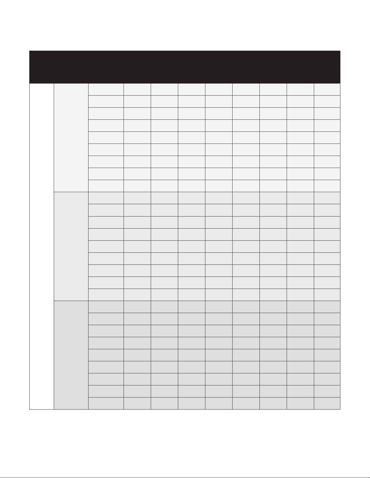
Exposure Category B
Interior Zone
Appendix A: Span Tables
Roof
Zone
Interior
Roof Slope
0-7°
<2:12
>7-27°
2:12 - 6:12
Ground
Snow Load
(psf)
0 48" 48" 48" 48" 24" 24" 24" 24"
10 48" 48" 48" 48" 24" 24" 24" 24"
20 48" 48" 48" 48" 24" 24" 24" 24"
30 48" 48" 48" 48" 24" 24" 24" 24"
40 48" 48" 48" 48" 24" 24" 24" 24"
50 48" 48" 48" 48" 24" 24" 24" 24"
60 24" 24" 24" 24" 24" 24" 24" 24"
70 24" 24" 24" 24" 24" 24" 24" 24"
75 24" 24" 24" 24" 24" 24" 24" 24"
0 48" 48" 48" 48" 24" 24" 24" 24"
10 48" 48" 48" 48" 24" 24" 24" 24"
20 48" 48" 48" 48" 24" 24" 24" 24"
30 48" 48" 48" 48" 24" 24" 24" 24"
40 48" 48" 48" 48" 24" 24" 24" 24"
50 48" 48" 48" 48" 24" 24" 24" 24"
85 90 100 110 120 130 140 150
Wind Speed (mph)
>27-45°
7:12 - 12:12
60 24" 24" 24" 24" 24" 24" 24" 24"
70 24" 24" 24" 24" 24" 24" 24" 24"
75 24" 24" 24" 24" 24" 24" 24" 24"
0 48" 48" 48" 48" 48" 48" 24" 24"
10 48" 48" 48" 48" 48" 48" 24" 24"
20 48" 48" 48" 48" 48" 48" 24" 24"
30 48" 48" 48" 48" 48" 48" 24" 24"
40 48" 48" 48" 48" 48" 48" 24" 24"
50 48" 48" 48" 48" 48" 48" 24" 24"
60 48" 48" 48" 48" 48" 48" 24" 24"
70 48" 48" 48" 48" 48" 48" 24" 24"
75 48" 48" 48" 48" 48" 48" 24" 24"
24” = 609.6 mm | 48” = 1219.2 mm
57
Page 64

sunMAX™ Solar User Guide
Edge Zone
Roof
Zone
Roof Slope
0-7°
<2:12
Ground
Snow Load
(psf)
0 48" 48" 48" 24" 24" 24" 24" 24"
10 48" 48" 48" 24" 24" 24" 24" 24"
20 48" 48" 48" 24" 24" 24" 24" 24"
30 48" 48" 48" 24" 24" 24" 24" 24"
40 48" 48" 48" 24" 24" 24" 24" 24"
50 48" 48" 48" 24" 24" 24" 24" 24"
60 24" 24" 24" 24" 24" 24" 24" 24"
70 24" 24" 24" 24" 24" 24" 24" 24"
75 24" 24" 24" 24" 24" 24" 24" 24"
0 48" 48" 24" 24" 24" 24" 24" 24"
10 48" 48" 24" 24" 24" 24" 24" 24"
20 48" 48" 24" 24" 24" 24" 24" 24"
85 90 100 110 120 130 140 150
Wind Speed (mph)
Edge
>7-27°
2:12 - 6:12
>27-45°
7:12 - 12:12
30 48" 48" 24" 24" 24" 24" 24" 24"
40 48" 48" 24" 24" 24" 24" 24" 24"
50 48" 48" 24" 24" 24" 24" 24" 24"
60 24" 24" 24" 24" 24" 24" 24" 24"
70 24" 24" 24" 24" 24" 24" 24" 24"
75 24" 24" 24" 24" 24" 24" 24" 24"
0 48" 48" 48" 48" 48" 24" 24" 24"
10 48" 48" 48" 48" 48" 24" 24" 24"
20 48" 48" 48" 48" 48" 24" 24" 24"
30 48" 48" 48" 48" 48" 24" 24" 24"
40 48" 48" 48" 48" 48" 24" 24" 24"
50 48" 48" 48" 48" 48" 24" 24" 24"
60 48" 48" 48" 48" 48" 24" 24" 24"
70 48" 48" 48" 48" 48" 24" 24" 24"
75 48" 48" 48" 48" 48" 24" 24" 24"
58
24” = 609.6 mm | 48” = 1219.2 mm
Page 65

Exposure Category C
Interior Zone
Appendix A: Span Tables
Roof
Zone
Roof Slope
0-7°
<2:12
Ground
Snow Load
(psf)
0 48" 48" 48" 24" 24" 24" 24" 24"
10 48" 48" 48" 24" 24" 24" 24" 24"
20 48" 48" 48" 24" 24" 24" 24" 24"
30 48" 48" 48" 24" 24" 24" 24" 24"
40 48" 48" 48" 24" 24" 24" 24" 24"
50 48" 48" 48" 24" 24" 24" 24" 24"
60 24" 24" 24" 24" 24" 24" 24" 24"
70 24" 24" 24" 24" 24" 24" 24" 24"
75 24" 24" 24" 24" 24" 24" 24" 24"
0 48" 48" 48" 24" 24" 24" 24" 24"
10 48" 48" 48" 24" 24" 24" 24" 24"
20 48" 48" 48" 24" 24" 24" 24" 24"
85 90 100 110 120 130 140 150
Wind Speed (mph)
Interior
>7-27°
2:12 - 6:12
>27-45°
7:12 - 12:12
30 48" 48" 48" 24" 24" 24" 24" 24"
40 48" 48" 48" 24" 24" 24" 24" 24"
50 48" 48" 48" 24" 24" 24" 24" 24"
60 24" 24" 24" 24" 24" 24" 24" 24"
70 24" 24" 24" 24" 24" 24" 24" 24"
75 24" 24" 24" 24" 24" 24" 24" 24"
0 48" 48" 48" 48" 48" 24" 24" 24"
10 48" 48" 48" 48" 48" 24" 24" 24"
20 48" 48" 48" 48" 48" 24" 24" 24"
30 48" 48" 48" 48" 48" 24" 24" 24"
40 48" 48" 48" 48" 48" 24" 24" 24"
50 48" 48" 48" 48" 48" 24" 24" 24"
60 48" 48" 48" 48" 48" 24" 24" 24"
70 48" 48" 48" 48" 48" 24" 24" 24"
75 48" 48" 48" 48" 24" 24" 24" 24"
24” = 609.6 mm | 48” = 1219.2 mm
59
Page 66

sunMAX™ Solar User Guide
Edge Zone
Roof
Zone
Roof Slope
0-7°
<2:12
Ground
Snow Load
(psf)
0 48" 24" 24" 24" 24" 24" 24" N/A
10 48" 24" 24" 24" 24" 24" 24" N/A
20 48" 24" 24" 24" 24" 24" 24" N/A
30 48" 24" 24" 24" 24" 24" 24" N/A
40 48" 24" 24" 24" 24" 24" 24" N/A
50 48" 24" 24" 24" 24" 24" 24" N/A
60 24" 24" 24" 24" 24" 24" 24" N/A
70 24" 24" 24" 24" 24" 24" 24" N/A
75 24" 24" 24" 24" 24" 24" 24" N/A
0 48" 48" 24" 24" 24" 24" 24" N/A
10 48" 48" 24" 24" 24" 24" 24" N/A
20 48" 48" 24" 24" 24" 24" 24" N/A
85 90 100 110 120 130 140 150
Wind Speed (mph)
Edge
>7-27°
2:12 - 6:12
>27-45°
7:12 - 12:12
30 48" 48" 24" 24" 24" 24" 24" N/A
40 48" 48" 24" 24" 24" 24" 24" N/A
50 48" 48" 24" 24" 24" 24" 24" N/A
60 48" 24" 24" 24" 24" 24" 24" N/A
70 48" 24" 24" 24" 24" 24" 24" N/A
75 48" 24" 24" 24" 24" 24" 24" N/A
0 48" 48" 48" 48" 24" 24" 24" 24"
10 48" 48" 48" 48" 24" 24" 24" 24"
20 48" 48" 48" 48" 24" 24" 24" 24"
30 48" 48" 48" 48" 24" 24" 24" 24"
40 48" 48" 48" 48" 24" 24" 24" 24"
50 48" 48" 48" 48" 24" 24" 24" 24"
60 48" 48" 48" 48" 24" 24" 24" 24"
70 48" 48" 48" 48" 24" 24" 24" 24"
75 48" 48" 48" 48" 24" 24" 24" 24"
60
24” = 609.6 mm | 48” = 1219.2 mm
Page 67
Exposure Category D
Interior Zone
Appendix A: Span Tables
Roof
Zone
Roof Slope
0-7°
<2:12
Ground
Snow Load
(psf)
0 48" 48" 24" 24" 24" 24" 24" 24"
10 48" 48" 24" 24" 24" 24" 24" 24"
20 48" 48" 24" 24" 24" 24" 24" 24"
30 48" 48" 24" 24" 24" 24" 24" 24"
40 48" 48" 24" 24" 24" 24" 24" 24"
50 48" 48" 24" 24" 24" 24" 24" 24"
60 48" 48" 24" 24" 24" 24" 24" 24"
70 48" 48" 24" 24" 24" 24" 24" 24"
75 48" 48" 24" 24" 24" 24" 24" 24"
0 48" 48" 24" 24" 24" 24" 24" 24"
10 48" 48" 24" 24" 24" 24" 24" 24"
20 48" 48" 24" 24" 24" 24" 24" 24"
85 90 100 110 120 130 140 150
Wind Speed (mph)
Interior
>7-27°
2:12 - 6:12
>27-45°
7:12 - 12:12
30 48" 48" 24" 24" 24" 24" 24" 24"
40 48" 48" 24" 24" 24" 24" 24" 24"
50 48" 48" 24" 24" 24" 24" 24" 24"
60 24" 24" 24" 24" 24" 24" 24" 24"
70 24" 24" 24" 24" 24" 24" 24" 24"
75 24" 24" 24" 24" 24" 24" 24" 24"
0 48" 48" 48" 24" 24" 24" 24" 24"
10 48" 48" 48" 24" 24" 24" 24" 24"
20 48" 48" 48" 24" 24" 24" 24" 24"
30 48" 48" 48" 24" 24" 24" 24" 24"
40 48" 48" 48" 24" 24" 24" 24" 24"
50 48" 48" 48" 24" 24" 24" 24" 24"
60 48" 48" 48" 24" 24" 24" 24" 24"
70 48" 48" 48" 24" 24" 24" 24" 24"
75 48" 48" 48" 24" 24" 24" 24" 24"
24” = 609.6 mm | 48” = 1219.2 mm
61
Page 68

sunMAX™ Solar User Guide
Edge Zone
Roof
Zone
Roof Slope
0-7°
<2:12
Ground
Snow Load
(psf)
0 24" 24" 24" 24" 24" 24" N/A N/A
10 24" 24" 24" 24" 24" 24" N/A N/A
20 24" 24" 24" 24" 24" 24" N/A N/A
30 24" 24" 24" 24" 24" 24" N/A N/A
40 24" 24" 24" 24" 24" 24" N/A N/A
50 24" 24" 24" 24" 24" 24" N/A N/A
60 24" 24" 24" 24" 24" 24" N/A N/A
70 24" 24" 24" 24" 24" 24" N/A N/A
75 24" 24" 24" 24" 24" 24" N/A N/A
0 24" 24" 24" 24" 24" 24" N/A N/A
10 24" 24" 24" 24" 24" 24" N/A N/A
20 24" 24" 24" 24" 24" 24" N/A N/A
85 90 100 110 120 130 140 150
Wind Speed (mph)
Edge
>7-27°
2:12 - 6:12
>27-45°
7:12 - 12:12
30 24" 24" 24" 24" 24" 24" N/A N/A
40 24" 24" 24" 24" 24" 24" N/A N/A
50 24" 24" 24" 24" 24" 24" N/A N/A
60 24" 24" 24" 24" 24" 24" N/A N/A
70 24" 24" 24" 24" 24" 24" N/A N/A
75 24" 24" 24" 24" 24" 24" N/A N/A
0 48" 48" 48" 24" 24" 24" 24" 24"
10 48" 48" 48" 24" 24" 24" 24" 24"
20 48" 48" 48" 24" 24" 24" 24" 24"
30 48" 48" 48" 24" 24" 24" 24" 24"
40 48" 48" 48" 24" 24" 24" 24" 24"
50 48" 48" 48" 24" 24" 24" 24" 24"
60 48" 48" 48" 24" 24" 24" 24" 24"
70 48" 48" 48" 24" 24" 24" 24" 24"
75 48" 48" 48" 24" 24" 24" 24" 24"
62
24” = 609.6 mm | 48” = 1219.2 mm
Page 69

Appendix B: Tile Roof
Additional Tile Roof Mount Requirements
• Angle grinder/saw with a masonry blade
• Roofing paper and roofing cement
Roof Mount and Flashing Installation
Subflashing
1. Install the threaded studs into the Roof Mounts by turning them clockwise until they bottom out.
Appendix B: Tile Roof
2. Mark the location of the first row of Roof Mounts by placing a chalk line horizontally across the roof. This chalk line
should be 1.5" (38mm) up from where the lower edge of the AC Module will sit.
3. Mark the front edge of a row of tiles to designate the location of the roof’s rafters.
63
Page 70

sunMAX™ Solar User Guide
4. Using the larger, upper Flashing as a guide, ensure that the upper edge of the Flashing will sit at least 1" (25 mm)
under the front edge of tiles in the course above. If the Flashing does not extend up underneath the course of tiles
above, adjust it along the vertical chalk line until it does.
5. Mark the location of the second row of Roof Mounts by placing a parallel chalk line above the first, using the
following guidelines:
• For portrait configurations, mark 66" (1675 mm) up from the previous chalk line.
• For landscape configurations, mark 40.13" (1020 mm) up from the previous chalk line.
For additional rows, repeat this step as needed.
40 and 1/8" (1020 mm) Landscape
66" (1675 mm) Portrait
6. Use a roofing bar, remove the tiles from locations where Roof Mounts will be installed.
7. Clear the mounting surface area of any dirt or debris.
64
Page 71

8. Using chalk or crayon, locate and mark the vertical rafter locations on the underlayment surface.
9. Transfer the horizontal chalk lines from the tiles to the underlayment below.
Appendix B: Tile Roof
10. Place a Roof Mount on the underlayment and line up the vertical holes in the mount base with the chalk line.
65
Page 72

sunMAX™ Solar User Guide
11. Pre-drill two penetration points along the vertical axis using the roof mount holes as your template. To avoid
damaging the roof mount base, do not drill all the way through to the rafter with it in place.
12. Remove the Roof Mount and complete the two pre-drilled holes that you started until they penetrate the roof’s
surface and drill into the rafter approximately 2.5" (63.5 mm) down.
13. Apply roofing sealant to both pre-drilled holes, completely covering both openings.
14. Place the roof mount back into position, lining up the larger vertical holes with the pre-drilled holes on the roof’s
underlayment. Using the lag bolts, secure the roof mount to the underlayment. To prevent damaging the surface of
the roof, do not overtighten the lag bolts.
With the roof mount in place, use one of the two methods available to install the subflashing: “Bibbing Method” on
page 67 or “Three-Course Method” on page 69. Both methods are just as effective, but use different material to
cover the flashing. Bibbing uses roofing paper and the three-course method uses roofing cement and felt paper. Please
proceed to the section that applies to the installation method of your choice.
66
Page 73

Appendix B: Tile Roof
Bibbing Method
1. Cut a piece of roofing paper about 14" (350 mm) wide that extends up underneath the next course of underlayment
above the roof mount.
2. Apply roofing sealant, in the shape of an arch, to the underside surface of the subflashing. The non-sealed end
should face downroof.
3. Place the subflashing over the roof mount with the Ubiquiti logo facing downroof.
Note: If the batten prevents proper placement of the roofing paper or subflashing, use a roofing bar to pry
and lift the batten high enough to slide under. If necessary, remove any nails or staples securing the batten
to the underlayment surface.
4. Press the subflashing firmly down onto the underlayment to ensure a watertight installation.
67
Page 74

sunMAX™ Solar User Guide
5. Apply a minimum of 0.25" (6 mm) continuous roofing sealant around the gap between the subflashing and the neck
of the roof mount.
6. Install the rubber counter flashing over the neck of the roof mount and press it down firmly onto the roofing sealant
you applied in the previous step.
7. Cut a piece of felt paper and place over the top half of the subflashing, including the edges, and ensure that it rests
flush on its surface.
68
Page 75

Appendix B: Tile Roof
8. If necessary, secure the felt paper in place using roofing nails. Apply roofing cement over the head of each nail,
covering it at least 1" (25 mm) all the way around and 0.13" thick (3 mm).
9. Reinstall any battens that may have been loosened during the installation of the subflashing.
10. Refer to “Upper Flashing” on page 71 to complete the installation.
Three-Course Method
1. Apply roofing sealant, in the shape of an arch, to the underside surface of the subflashing. The non-sealed end
should face downroof.
2. Place the subflashing over the roof mount with the Ubiquiti logo facing downroof.
Note: If the batten obstructs proper placement of the subflashing, use a roofing bar to pry and lift the
batten high enough to slide the subflashing under. If necessary, remove any nails or staples securing the
batten to the underlayment surface.
69
Page 76

sunMAX™ Solar User Guide
3. Press the subflashing firmly down onto the underlayment to ensure a watertight installation.
4. Apply a minimum of 0.25" (6 mm) continuous roofing sealant around the gap between the subflashing and the neck
of the Roof Mount.
5. Install the rubber counter flashing over the neck of the roof mount and press it down firmly onto the roofing sealant.
70
Page 77

Appendix B: Tile Roof
6. Apply a layer (0.13" or 3 mm minimum thickness) of elastomeric roof cement around the top three sides of the
subflashing. The cement should cover at least 2" (50 mm) on both the flashing and the roof surface.
7. Cut a piece of reinforcing fabric and press it into the cemented area before it dries. Then apply another layer (0.13"or
3 mm minimum thickness) of elastomeric roof cement over the fabric.
Upper Flashing
1. Mark the tiles surrounding each mount location in order to identify the center of the Roof Mount.
2. Replace the tile(s) above the Roof Mount and mark the area of the tile that needs to be cut in order to expose the
Roof Mount and subflashing. You can use the same tile mark to locate the center of the Roof Mount below.
71
Page 78

sunMAX™ Solar User Guide
3. Remove the tile(s) and cut out the marked section to expose the roof mount and subflashing. Use caution when
cutting to avoid breaking or damaging the tile(s).
Note: Use a diamond cutting blade or a masonry core bit to create an opening in the tile(s).
4. Replace the tile(s) and ensure you have access to the top surface of the Roof Mount below.
72
Page 79

Appendix B: Tile Roof
5. For curved tiles, the upper Flashing needs to be shaped to the profile of the roof’s tiles. Position the opening of the
Flashing directly over the Roof Mount and form the Flashing to the curvature of the tiles.
6. Slide the top edge of the Flashing underneath the course of tiles above.
7. Center the opening in the Flashing directly over the center of the Roof Mount below.
73
Page 80

sunMAX™ Solar User Guide
8. Install the extension post onto the threaded stud below by lowering it through the Flashing and turning it clockwise
until it bottoms out.
9. Apply a minimum of 0.25" (6 mm) of continuous roofing sealant around the gap between the Flashing and the neck
of the extension post.
10. Install the rubber counter flashing over the neck of the extension post and slide it down firmly onto the roofing
sealant you applied in the previous step.
With the Roof Mounts and Flashing in place, refer to “Mounting Assembly Installation” on page 36 to continue the
installation of your solar array.
74
Page 81

sunMAX™ Solar User Guide
Appendix C: Contact Information
Ubiquiti Networks Support
Ubiquiti Support Engineers are located around the world and
are dedicated to helping customers resolve software, hardware
compatibility, or field issues as quickly as possible. We strive to
respond to support inquiries within a 24-hour period.
Ubiquiti Networks, Inc.
2580 Orchard Parkway
San Jose, CA 95131
www.ubnt.com
Online Resources
Support: support.ubnt.com
Community: community.ubnt.com
Downloads: downloads.ubnt.com
Live Chat: sunlink.ubnt.com
Appendix C: Contact Information
Ubiquiti Networks, Inc.
AJ121515
75
Page 82

www.ubnt.com
©2015 Ubiquiti Networks, Inc. All rights reserved. Ubiquiti, Ubiquiti Networks, the Ubiquiti U logo, the Ubiquiti beam logo, and sunMAX, are trademarks
or registered trademarks of Ubiquiti Networks, Inc. in the United States and in other countries. Google™, Android™, Google Play™ and other marks are
trademarks of Google Inc. All other trademarks are the property of their respective owners.
 Loading...