

Page 1
5 GHz High‑Performance
airMAX® ac Bridge
Model: PBE‑5AC‑Gen2
Page 2
Introduction
Thank you for purchasing the Ubiquiti Networks®
PowerBeam®AC Gen 2. This Quick Start Guide is designed to
guide you through installation and includes warranty terms.
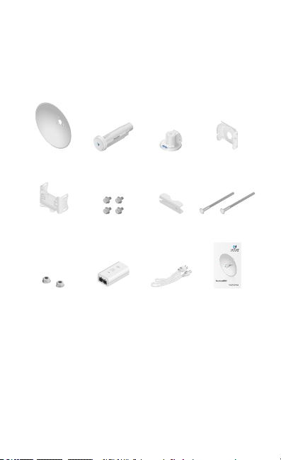
Package Contents
Dish Reflector Antenna Feed Rear Housing Adjustment
Bracket
Mounting
Bracket
Flange Nuts
(Qty. 2)
TERMS OF USE: Ubiquiti radio devices must be professionally installed. Shielded Ethernet
cable and earth grounding must be used as conditions of product warranty. TOUGHCable™ is
designed for outdoor installations. It is the customer’s responsibility to follow local country
regulations, including operation within legal frequency channels, output power, and Dynamic
Frequency Selection (DFS) requirements.
Hex Bolts with
Washers (Qty. 4)
Gigabit PoE
(24V, 0.5A) with
Mounting Bracket
Pole
Clamp
Power Cord Quick Start
Long Carriage
Bolts (Qty. 2)
5 GHz High‑Performance
®
ac Bridge
airMAX
Model: PBE‑5AC‑Gen2
Guide
Page 3
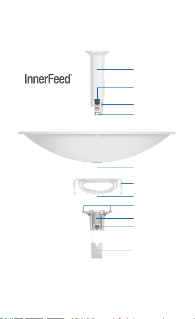
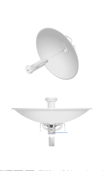
Hardware Overview
Bottom View
Antenna Feed
Technology
Ethernet Port
Reset Button
Release Button
Dish Reflector
Adjustment Bracket
Carrying Handle/
Lifting Loop
Alignment Pins
Rear Housing
Release Button Slot
Cable Door
Page 4
Reset Button To reset to factory defaults, press and hold the
Reset button for more than 10 seconds while the PowerBeam
is already poweredon. Alternatively, the PowerBeam may be
reset remotely via a Reset button located on the bottom of the
Gigabit PoE Adapter.
Release Button After you assemble the PowerBeam, check
the Release button; it should be fully engaged in the Release
Button Slot of the Rear Housing. This ensures that the Antenna
Feed is locked into place. If you need to remove the Antenna
Feed, you must depress the Release button first.
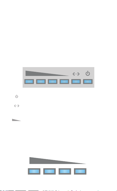
LEDs
Power The Power LED will light blue when the
device is connected to a power source.
Ethernet The Ethernet LED will light steady blue
when an active Ethernet connection is made and
flash when there is activity.
Signal In airOS®, you can modify the threshold
value for the wireless signal strength LEDs on the
Wireless tab under Signal LED Thresholds. Each LED
will light when the wireless signal strength is equal
to or greater than the LED’s threshold value. The
default threshold values for these LEDs are shown
below:
-73 dBm
-65 dBm
-80 dBm -94 dBm
Page 5
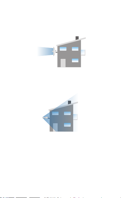
Application Examples
The PowerBeam mounted outdoors with the Dish Reflector
installed provides directional outdoor coverage (gain is
reflector‑dependent).
The PowerBeam mounted outdoors without the Dish Reflector
installed provides outdoor‑to‑indoor coverage using the 3 dBi
Antenna Feed only.
Installation Requirements
• 13 mm wrench
• Shielded Category 5 (or above) cabling should be used for
all wired Ethernet connections and should be grounded
through the AC ground of the PoE.
We recommend that you protect your networks from
harmful outdoor environments and destructive ESD events
with industrial‑grade, shielded Ethernet cable from Ubiquiti
Networks. For more details, visit www.ubnt.com/toughcable
Page 6
Installation
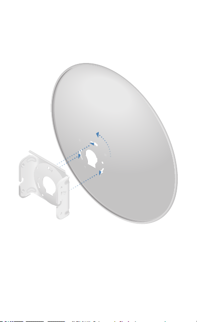
1. Align and insert the tabs of the Adjustment Bracket into the
slots of the Dish Reflector. Rotate the Adjustment Bracket
counterclockwise until the alignment holes in the dish and
bracket align with each other.
Page 7
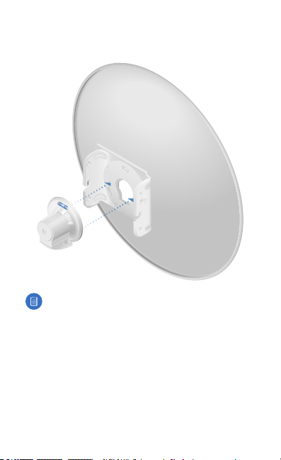
2. Line up the Alignment Pins of the Rear Housing with the
alignment holes of the Adjustment Bracket. Push the Rear
Housing into the Adjustment Bracket.
Note: In high‑wind environments, you can add support
with additional hardware (not included):
1. Using the four holes in the Adjustment Bracket as a
template, drill four holes into the Dish Reflector with a
4.4 mm or 11/64" drill bit.
2. Secure the Dish Reflector to the Adjustment Bracket
using M4 screws, washers, and nuts (not included).
Page 8
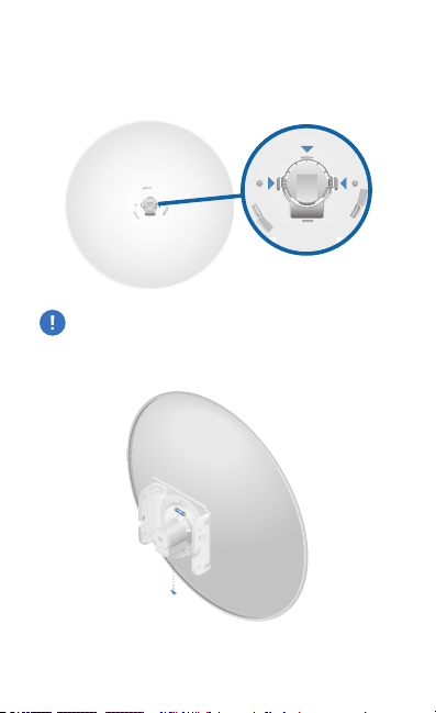
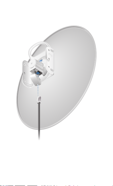
3. View the Dish Reflector from the front. Ensure that the
three hooks (indicated below) of the Rear Housing are
fully engaged with the inner wall of the Dish Reflector and
locked into place.
IMPORTANT: Before proceeding, lightly pull the Rear
Housing to confirm that it is locked into place.
4. Push in the sides of the Cable Door and detach it from the
Rear Housing.
*640-00272-04*
640-00272-04
Page 9
5. Attach the Antenna Feed.
a. Insert the Antenna Feed into the Rear Housing, and push
until it locks into place with a click.
b. Lightly pull the Antenna Feed to ensure that it is locked
into place and the Release Button is fully engaged.
Release
Button
Bottom View
Page 10
6. Connect an Ethernet cable to the Ethernet Port of the
Antenna Feed. Then re‑attach the Cable Door to the
RearHousing.
Page 11

7. Attach the Pole Clamp to the Mounting Bracket.
a. Hold the Mounting Bracket with its clamps facing you
and the Elevation Indicators towards the top.
b. Insert the two Long Carriage Bolts through the holes of
the Mounting Bracket.
c. Slide the hole of the Pole Clamp over one bolt of the
Mounting Bracket.
d. Place one Flange Nut on each bolt.
Elevation
Indicator
Page 12
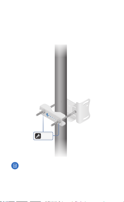
8. Mount the Mounting Bracket on the pole and secure it.
a. Place the Mounting Bracket against the pole.
b. Slide the slot of the Pole Clamp over the adjacent
Carriage Bolt.
c. Tighten the Flange Nuts of the bolts to 25 N ∙ m to
secure the Mounting Bracket to the pole.
25 N ∙ m
Note: The mounting assembly can accommodate a
Ø 40 ‑ 80 mm pole.
Page 13

9. Locate the two slots on the Adjustment Bracket and the two
pivot pins on the Mounting Bracket. Place the Reflector Dish
with the attached Mounting Bracket onto the pivot pins,
ensuring that they fit securely inside of the slots.
Adjustment
Bracket Slot
Pivot Pin
(one on each side of
Mounting Bracket)
Page 14

10. Install the four Hex Bolts with Washers into the Mounting
Bracket. Do not tighten the four Hex Bolts completely.
Page 15

11. Adjust the elevation angle.
a. Pivot the antenna until the Elevation Indicator shows
the desired elevation angle.
b. Tighten the four Hex Bolts completely.
20°
20°
Elevation
Indicator
Page 16

Connect the power using one of the following options:
• Using the included Gigabit PoE Adapter: Go to “Connecting
to the PoE Adapter”.
• Using a separate PoE switch: Connect the Ethernet cable
from the PowerBeam’s Ethernet port to a PoE‑enabled
Ethernet port on the switch.
WARNING: The switch port must comply with the
power specifications listed in the Specifications
section of this Quick Start Guide.
Connecting to the PoE Adapter
1. Connect the Ethernet cable from the PowerBeam’s Ethernet
port to the POE port of the Gigabit PoE adapter.
2. Connect an Ethernet cable from your LAN to the adapter’s
LAN port.
3. Connect the Power Cord to the adapter’s power port.
Connect the other end of the Power Cord to a power outlet.
Mounting the PoE Adapter (Optional)
1. Remove the PoE Mounting Bracket from the adapter, place
the bracket at the desired location, and mark the two holes.
2. Pre‑drill the holes if necessary, and secure the bracket
using two fasteners (not included).
3. Align the adapter’s slots with the tabs of the PoE Mounting
Bracket, and then slide the adapterdown.
Page 17

Accessing airOS via Wi‑Fi
Verify connectivity in the airOS Configuration Interface. There
are two methods, the U Mobile App and Web Portal. Both are
available for 15 minutes immediately after you power on the
PowerBeam. If necessary, you can power cycle the PowerBeam
to re‑enable its Wi‑Fi.
Proceed to the appropriate instructions:
U Mobile App
1. Download the U Mobile app from the AppStore (iOS) or
Google Play™ (Android).
2. Connect your device’s Wi‑Fi to the PowerBeam SSID
named: PBE-5AC-Gen2:<MAC Address>
Note: Ensure that DHCP is enabled on your
Wi‑Fiadapter.
3. Launch the app.
4. Tap the PowerBeam on the Connections screen.
Page 18

5. Tap Connect on the Login screen.
6. Select your Country and tap Done.
Page 19

7. Customize your settings as needed.
Page 20

Web Portal
1. Connect your device’s Wi‑Fi to the PowerBeam SSID
named: PBE-5AC-Gen2:<MAC Address>
Note: Ensure that your Wi‑Fi connection has DHCP
enabled.
2. Launch a web browser and go to: http://setup.ubnt.com
3. Enter ubnt in the Username and Password fields. Select
your Country and Language. You must agree to the Terms of
Use to use the product. Click Login.
Note: The Country setting for U.S. product versions is
restricted to a choice of Canada, Puerto Rico, or the
U.S. to ensure compliance with FCC/IC regulations.
The airOS Configuration Interface will appear, allowing you
to customize your settings as needed. For additional details
on the airOS Configuration Interface, refer to the User Guide
available at documentation.ubnt.com/airmax
Page 21

Installer Compliance Responsibility
Devices must be professionally installed and it is the
professional installer’s responsibility to make sure the device is
operated within local country regulatory requirements.
Since Ubiquiti Networks equipment can be paired with a
variety of antennas and cables, the Antenna and Output Power
fields are provided to the professional installer to assist in
meeting regulatory requirements.
Page 22

Specifications
Dimensions 420 x 420 x 230 mm
Weight 2.22 kg
Gain 25 dBi
Networking Interface (1) 10/100/1000 Ethernet Port
Processor MIPS 74Kc
Enclosure Characteristics
Antenna Feed
Dish Reector
Max. Power Consumption 8.5W
Power Supply 24V, 0.5A Gigabit PoE Adapter (Included)
Power Method Passive PoE (Pairs 4, 5+; 7, 8 Return)
Supported Voltage Range 20 to 26VDC
Wind Loading 380 N @ 200 km/h
Wind Survivability 200 km/h
Mounting Pole Mounting Kit Included
Operating Temperature ‑40 to 70° C (‑40 to 158° F)
Operating Humidity 5 to 95% Noncondensing
Shock and Vibrations ETSI300‑019‑1.4
Certications CE, FCC, IC
Worldwide
USA
PBE‑5AC‑Gen2
(16.54 x 16.54 x 9.06")
(4.89 lb)
Outdoor UV Stabilized Plastic
Powder‑Coated SPCC
(85.4 lbf @ 125 mph)
(125 mph)
Operating Frequency (MHz)
U-NII-1 U‑NII‑2A U‑NII‑2C U‑NII‑3
5150 ‑ 5250 5250 ‑ 5350 5470 ‑ 5725 5725 ‑ 5850
2400‑2483.5
5150 ‑ 5875
Page 23

Safety Notices
1. Read, follow, and keep these instructions.
2. Heed all warnings.
3. Only use attachments/accessories specified by the manufacturer.
WARNING: Do not use this product in location that can
be submerged by water.
WARNING: Avoid using this product during an electrical
storm. There may be a remote risk of electric shock from
lightning.
Electrical Safety Information
1. Compliance is required with respect to voltage, frequency, and current
requirements indicated on the manufacturer’s label. Connection to a
different power source than those specified may result in improper
operation, damage to the equipment or pose a fire hazard if the
limitations are not followed.
2. There are no operator serviceable parts inside this equipment. Service
should be provided only by a qualified service technician.
3. This equipment is provided with a detachable power cord which has
an integral safety ground wire intended for connection to a grounded
safety outlet.
a. Do not substitute the power cord with one that is not the provided
approved type. Never use an adapter plug to connect to a 2‑wire
outlet as this will defeat the continuity of the grounding wire.
b. The equipment requires the use of the ground wire as a part of the
safety certification, modification or misuse can provide a shock
hazard that can result in serious injury or death.
c. Contact a qualified electrician or the manufacturer if there
are questions about the installation prior to connecting the
equipment.
d. Protective earthing is provided by Listed AC adapter. Building
installation shall provide appropriate short‑circuit backup
protection.
e. Protective bonding must be installed in accordance with local
national wiring rules and regulations.
Page 24

Limited Warranty
UBIQUITI NETWORKS, Inc (“UBIQUITI NETWORKS”) warrants that the
product(s) furnished hereunder (the “Product(s)”) shall be free from defects
in material and workmanship for a period of one (1) year from the date
of shipment by UBIQUITI NETWORKS under normal use and operation.
UBIQUITI NETWORKS’ sole and exclusive obligation and liability under
the foregoing warranty shall be for UBIQUITI NETWORKS, at its discretion,
to repair or replace any Product that fails to conform to the above
warranty during the above warranty period. The expense of removal and
reinstallation of any Product is not included in this warranty. The warranty
period of any repaired or replaced Product shall not extend beyond its
original term.
Warranty Conditions
The above warranty does not apply if the Product:
(I) has been modified and/or altered, or an addition made thereto,
except by Ubiquiti Networks, or Ubiquiti Networks’ authorized
representatives, or as approved by Ubiquiti Networks in writing;
(II) has been painted, rebranded or physically modified in any way;
(III) has been damaged due to errors or defects in cabling;
(IV) has been subjected to misuse, abuse, negligence, abnormal
physical, electromagnetic or electrical stress, including lightning
strikes, or accident;
(V) has been damaged or impaired as a result of using third party
firmware;
(VI) has no original Ubiquiti MAC label, or is missing any other original
Ubiquiti label(s); or
(VII) has not been received by Ubiquiti within 30 days of issuance of
the RMA.
In addition, the above warranty shall apply only if: the product has been
properly installed and used at all times in accordance, and in all material
respects, with the applicable Product documentation; all Ethernet cabling
runs use CAT5 (or above), and for outdoor installations, shielded Ethernet
cabling is used, and for indoor installations, indoor cabling requirements
are followed.
Returns
No Products will be accepted for replacement or repair without obtaining
a Return Materials Authorization (RMA) number from UBIQUITI NETWORKS
during the warranty period, and the Products being received at UBIQUITI
NETWORKS’ facility freight prepaid in accordance with the RMA process of
UBIQUITI NETWORKS. Products returned without an RMA number will not
be processed and will be returned freight collect or subject to disposal.
Information on the RMA process and obtaining an RMA number can be
found at: www.ubnt.com/support/warranty.
Page 25

Disclaimer
EXCEPT FOR ANY EXPRESS WARRANTIES PROVIDED HEREIN, UBIQUITI
NETWORKS, ITS AFFILIATES, AND ITS AND THEIR THIRD PARTY DATA,
SERVICE, SOFTWARE AND HARDWARE PROVIDERS HEREBY DISCLAIM
AND MAKE NO OTHER REPRESENTATION OR WARRANTY OF ANY KIND,
EXPRESS, IMPLIED OR STATUTORY, INCLUDING, BUT NOT LIMITED TO,
REPRESENTATIONS, GUARANTEES, OR WARRANTIES OF MERCHANTABILITY,
ACCURACY, QUALITY OF SERVICE OR RESULTS, AVAILABILITY,
SATISFACTORY QUALITY, LACK OF VIRUSES, QUIET ENJOYMENT, FITNESS
FOR A PARTICULAR PURPOSE AND NON‑INFRINGEMENT AND ANY
WARRANTIES ARISING FROM ANY COURSE OF DEALING, USAGE OR
TRADE PRACTICE IN CONNECTION WITH SUCH PRODUCTS AND SERVICES.
BUYER ACKNOWLEDGES THAT NEITHER UBIQUITI NETWORKS NOR
ITS THIRD PARTY PROVIDERS CONTROL BUYER’S EQUIPMENT OR THE
TRANSFER OF DATA OVER COMMUNICATIONS FACILITIES, INCLUDING
THE INTERNET, AND THAT THE PRODUCTS AND SERVICES MAY BE
SUBJECT TO LIMITATIONS, INTERRUPTIONS, DELAYS, CANCELLATIONS
AND OTHER PROBLEMS INHERENT IN THE USE OF COMMUNICATIONS
FACILITIES. UBIQUITI NETWORKS, ITS AFFILIATES AND ITS AND THEIR THIRD
PARTY PROVIDERS ARE NOT RESPONSIBLE FOR ANY INTERRUPTIONS,
DELAYS, CANCELLATIONS, DELIVERY FAILURES, DATA LOSS, CONTENT
CORRUPTION, PACKET LOSS, OR OTHER DAMAGE RESULTING FROM ANY
OF THE FOREGOING. In addition, UBIQUITI NETWORKS does not warrant
that the operation of the Products will be error-free or that operation will
be uninterrupted. In no event shall UBIQUITI NETWORKS be responsible
for damages or claims of any nature or description relating to system
performance, including coverage, buyer’s selection of products (including
the Products) for buyer’s application and/or failure of products (including
the Products) to meet government or regulatory requirements.
Limitation of Liability
EXCEPT TO THE EXTENT PROHIBITED BY LOCAL LAW, IN NO EVENT WILL
UBIQUITI OR ITS SUBSIDIARIES, AFFILIATES OR SUPPLIERS BE LIABLE FOR
DIRECT, SPECIAL, INCIDENTAL, CONSEQUENTIAL OR OTHER DAMAGES
(INCLUDING LOST PROFIT, LOST DATA, OR DOWNTIME COSTS), ARISING
OUT OF THE USE, INABILITY TO USE, OR THE RESULTS OF USE OF THE
PRODUCT, WHETHER BASED IN WARRANTY, CONTRACT, TORT OR OTHER
LEGAL THEORY, AND WHETHER OR NOT ADVISED OF THE POSSIBILITY OF
SUCH DAMAGES.
Page 26

Note
Some countries, states and provinces do not allow exclusions of implied
warranties or conditions, so the above exclusion may not apply to you.
You may have other rights that vary from country to country, state to
state, or province to province. Some countries, states and provinces do not
allow the exclusion or limitation of liability for incidental or consequential
damages, so the above limitation may not apply to you. EXCEPT TO
THE EXTENT ALLOWED BY LOCAL LAW, THESE WARRANTY TERMS DO
NOT EXCLUDE, RESTRICT OR MODIFY, AND ARE IN ADDITION TO, THE
MANDATORY STATUTORY RIGHTS APPLICABLE TO THE LICENSE OF ANY
SOFTWARE (EMBEDDED IN THE PRODUCT) TO YOU. The United Nations
Convention on Contracts for the International Sale of Goods shall not apply
to any transactions regarding the sale of the Products.
Compliance
FCC
Changes or modifications not expressly approved by the party responsible
for compliance could void the user’s authority to operate the equipment.
This device complies with Part 15 of the FCC Rules. Operation is subject to
the following two conditions.
1. This device may not cause harmful interference, and
2. This device must accept any interference received, including
interference that may cause undesired operation.
This equipment has been tested and found to comply with the limits for a
Class A digital device, pursuant to Part 15 of the FCC Rules. These limits are
designed to provide reasonable protection against harmful interference
when the equipment is operated in a commercial environment. This
equipment generates, uses, and can radiate radio frequency energy and,
if not installed and used in accordance with the instruction manual, may
cause harmful interference to radio communications. Operations of this
equipment in a residential area is likely to cause harmful interference in
which case the user will be required to correct the interference at his own
expense.
This radio transmitter (FCC ID: SWX‑PBE5ACG2) has been approved by
FCC to operate with the antenna types listed below with the maximum
permissible gain and required antenna impedance for each antenna type
indicated. Antenna types not included in this list, having a gain greater
than the maximum gain indicated for that type, are strictly prohibited for
use with this device.
Antenna Information: Dish antenna, Gain: 25 dBi
Page 27

Industry Canada
CAN ICES‑3(A)/NMB‑3(A)
This Class A digital apparatus complies with Canadian CAN ICES‑003.
To reduce potential radio interference to other users, the antenna
type and its gain should be so chosen that the equivalent isotropically
radiated power (e.i.r.p.) is not more than that permitted for successful
communication.
This device complies with Industry Canada licence‑exempt RSS standard(s).
Operation is subject to the following two conditions:
1. This device may not cause interference, and
2. This device must accept any interference, including interference that
may cause undesired operation of the device.
This radio transmitter (IC: 6545A‑PBE5ACG2) has been approved by
Industry Canada to operate with the antenna types listed below with the
maximum permissible gain and required antenna impedance for each
antenna type indicated. Antenna types not included in this list, having a
gain greater than the maximum gain indicated for that type, are strictly
prohibited for use with this device.
Antenna Information: Dish antenna, Gain: 25 dBi
CAN ICES‑3(A)/NMB‑3(A)
Cet appareil numérique de la classe A est conforme à la norme NMB‑003
du Canada.
Pour réduire le risque d’interférence aux autres utilisateurs, le type
d’antenne et son gain doivent être choisies de façon que la puissance
isotrope rayonnée équivalente (PIRE) ne dépasse pas ce qui est nécessaire
pour une communication réussie.
Cet appareil est conforme à la norme RSS Industrie Canada exempts de
licence norme(s). Son fonctionnement est soumis aux deux conditions
suivantes:
1. Cet appareil ne peut pas provoquer d’interférences et
2. Cet appareil doit accepter toute interférence, y compris les
interférences qui peuvent causer un mauvais fonctionnement du
dispositif.
Cet émetteur radio (IC: 6545A‑PBE5ACG2) a été approuvée par Industrie
Canada pour l’exploitation avec l’antenne types énumérés ci‑dessous avec
le gain maximal admissible et requis l’impédance de l’antenne pour chaque
type d’antenne indiqué. Types d’antenne non inclus dans cette liste, ayant
un gain supérieur au gain maximal indiqué pour ce type, sont strictement
interdits pour une utilisation avec cet appareil.
Informations d’antenne: Antenne parabolique, Gain: 25 dBi
Page 28

RF Exposure Warning
The antennas used for this transmitter must be installed to provide a
separation distance of at least 20 cm from all persons and must not be
located or operating in conjunction with any other antenna or transmitter.
Les antennes utilisées pour ce transmetteur doivent être installé en
considérant une distance de séparation de toute personnes d’au moins
20cm et ne doivent pas être localisé ou utilisé en conflit avec tout autre
antenne ou transmetteur.
Australia and New Zealand
Warning: This is a Class A product. In a domestic environment this
product may cause radio interference in which case the user may
be required to take adequate measures.
CE Marking
CE marking on this product represents the product is in compliance with
all directives that are applicable to it.
Alert Sign (!) Follows CE Marking
Alert sign must be indicated if a restriction on use applied to the product
and it must follow the CE marking.
Page 29

RoHS/WEEE Compliance Statement
English
European Directive 2012/19/EU requires that the equipment bearing
this symbol on the product and/or its packaging must not be disposed
of with unsorted municipal waste. The symbol indicates that this
product should be disposed of separately from regular household waste
streams. It is your responsibility to dispose of this and other electric and
electronic equipment via designated collection facilities appointed by the
government or local authorities. Correct disposal and recycling will help
prevent potential negative consequences to the environment and human
health. For more detailed information about the disposal of your old
equipment, please contact your local authorities, waste disposal service, or
the shop where you purchased the product.
Deutsch
Die Europäische Richtlinie 2012/19/EU verlangt, dass technische
Ausrüstung, die direkt am Gerät und/oder an der Verpackung mit diesem
Symbol versehen ist, nicht zusammen mit unsortiertem Gemeindeabfall
entsorgt werden darf. Das Symbol weist darauf hin, dass das Produkt
von regulärem Haushaltmüll getrennt entsorgt werden sollte. Es
liegt in Ihrer Verantwortung, dieses Gerät und andere elektrische
und elektronische Geräte über die dafür zuständigen und von der
Regierung oder örtlichen Behörden dazu bestimmten Sammelstellen zu
entsorgen. Ordnungsgemäßes Entsorgen und Recyceln trägt dazu bei,
potentielle negative Folgen für Umwelt und die menschliche Gesundheit
zu vermeiden. Wenn Sie weitere Informationen zur Entsorgung Ihrer
Altgeräte benötigen, wenden Sie sich bitte an die örtlichen Behörden oder
städtischen Entsorgungsdienste oder an den Händler, bei dem Sie das
Produkt erworben haben.
Page 30

Español
La Directiva 2012/19/UE exige que los equipos que lleven este símbolo en
el propio aparato y/o en su embalaje no deben eliminarse junto con otros
residuos urbanos no seleccionados. El símbolo indica que el producto
en cuestión debe separarse de los residuos domésticos convencionales
con vistas a su eliminación. Es responsabilidad suya desechar este y
cualesquiera otros aparatos eléctricos y electrónicos a través de los puntos
de recogida que ponen a su disposición el gobierno y las autoridades
locales. Al desechar y reciclar correctamente estos aparatos estará
contribuyendo a evitar posibles consecuencias negativas para el medio
ambiente y la salud de las personas. Si desea obtener información más
detallada sobre la eliminación segura de su aparato usado, consulte a las
autoridades locales, al servicio de recogida y eliminación de residuos de su
zona o pregunte en la tienda donde adquirió el producto.
Français
La directive européenne 2012/19/UE exige que l’équipement sur lequel
est apposé ce symbole sur le produit et/ou son emballage ne soit pas jeté
avec les autres ordures ménagères. Ce symbole indique que le produit
doit être éliminé dans un circuit distinct de celui pour les déchets des
ménages. Il est de votre responsabilité de jeter ce matériel ainsi que tout
autre matériel électrique ou électronique par les moyens de collecte
indiqués par le gouvernement et les pouvoirs publics des collectivités
territoriales. L’élimination et le recyclage en bonne et due forme ont pour
but de lutter contre l’impact néfaste potentiel de ce type de produits
sur l’environnement et la santé publique. Pour plus d’informations sur le
mode d’élimination de votre ancien équipement, veuillez prendre contact
avec les pouvoirs publics locaux, le service de traitement des déchets, ou
l’endroit où vous avez acheté le produit.
Italiano
La direttiva europea 2012/19/UE richiede che le apparecchiature
contrassegnate con questo simbolo sul prodotto e/o sull’imballaggio non
siano smaltite insieme ai rifiuti urbani non differenziati. Il simbolo indica
che questo prodotto non deve essere smaltito insieme ai normali rifiuti
domestici. È responsabilità del proprietario smaltire sia questi prodotti sia
le altre apparecchiature elettriche ed elettroniche mediante le specifiche
strutture di raccolta indicate dal governo o dagli enti pubblici locali. Il
corretto smaltimento ed il riciclaggio aiuteranno a prevenire conseguenze
potenzialmente negative per l’ambiente e per la salute dell’essere umano.
Per ricevere informazioni più dettagliate circa lo smaltimento delle vecchie
apparecchiature in Vostro possesso, Vi invitiamo a contattare gli enti
pubblici di competenza, il servizio di smaltimento rifiuti o il negozio nel
quale avete acquistato il prodotto.
Page 31

Declaration of Conformity
Česky
[Czech]
Dansk
[Danish]
Nederlands
[Dutch]
English
Eesti
[Estonian]
Suomi
[Finnish]
Français
[French]
Deutsch
[German]
Ελληνική
[Greek]
Magyar
[Hungarian]
Íslenska
[Icelandic]
Italiano
[Italian]
Latviski
[Latvian]
Lietuviškai
[Lithuanian]
UBIQUITI NETWORKS tímto prohlašuje, že toto UBIQUITI
NETWORKS zařízení, je ve shod se základními požadavky a dalšími
příslušnými ustanoveními směrnice 1999/5/ES.
Hermed, UBIQUITI NETWORKS, erklærer at denne UBIQUITI
NETWORKS enhed, er i overensstemmelse med de væsentlige
krav og øvrige relevante krav i direktiv 1999/5/EF.
Hierbij verklaart UBIQUITI NETWORKS, dat deze UBIQUITI
NETWORKS apparaat, in overeenstemming is met de essentiële
eisen en de andere relevante bepalingen van richtlijn 1999/5/EC.
Hereby, UBIQUITI NETWORKS, declares that this UBIQUITI
NETWORKS device, is in compliance with the essential
requirements and other relevant provisions of Directive 1999/5/EC.
Käesolevaga UBIQUITI NETWORKS kinnitab, et antud UBIQUITI
NETWORKS seade, on vastavus olulistele nõuetele ja teistele
asjakohastele sätetele direktiivi 1999/5/EÜ.
Täten UBIQUITI NETWORKS vakuuttaa, että tämä UBIQUITI
NETWORKS laite, on yhdenmukainen olennaisten vaatimusten ja
muiden sitä koskevien direktiivin 1999/5/EY.
Par la présente UBIQUITI NETWORKS déclare que l’appareil
UBIQUITI NETWORKS, est conforme aux exigences essentielles et
aux autres dispositions pertinentes de la directive 1999/5/CE.
Hiermit erklärt UBIQUITI NETWORKS, dass sich dieses UBIQUITI
NETWORKS Gerät, in Übereinstimmung mit den grundlegenden
Anforderungen und den anderen relevanten Vorschriften der
Richtlinie 1999/5/EG befindet.
Δια του παρόντος, UBIQUITI NETWORKS, δηλώνει ότι αυτή η
συσκευή UBIQUITI NETWORKS, είναι σε συμμόρφωση με τις
βασικές απαιτήσεις και τις λοιπές σχετικές διατάξεις της οδηγίας
1995/5/ΕΚ.
Ezennel UBIQUITI NETWORKS kijelenti, hogy ez a UBIQUITI
NETWORKS készülék megfelel az alapvető követelményeknek és
más vonatkozó 1999/5/EK irányelv rendelkezéseit.
Hér, UBIQUITI NETWORKS, því yfir að þetta UBIQUITI NETWORKS
tæki er í samræmi við grunnkröfur og önnur viðeigandi ákvæði
tilskipun 1999/5/EC.
Con la presente, UBIQUITI NETWORKS, dichiara che questo
dispositivo UBIQUITI NETWORKS, è conforme ai requisiti essenziali
ed alle altre disposizioni pertinenti della direttiva 1999/5/CE.
Ar šo, UBIQUITI NETWORKS, deklarē, ka UBIQUITI NETWORKS
ierīce, ir saskaņā ar būtiskajām prasībām un citiem attiecīgiem
noteikumiem Direktīvā 1999/5/EK.
UBIQUITI NETWORKS deklaruoja, kad šis UBIQUITI NETWORKS
įrenginys atitinka esminius reikalavimus ir kitas 1999/5/EB
Direktyvos nuostatas.
Page 32

Malti
[Maltese]
Norsk
[Norwegian]
Polski
[Polish]
Português
[Portuguese]
Română
[Romanian]
Slovensky
[Slovak]
Español
[Spanish]
Svenska
[Swedish]
Hawnhekk, UBIQUITI NETWORKS, tiddikjara li dan il-mezz
UBIQUITI NETWORKS huwa konformi mar-rekwiżiti essenzjali u
dispożizzjonijiet rilevanti oħrajn ta ‘Direttiva 1999/5/EC.
Herved UBIQUITI NETWORKS, erklærer at denne UBIQUITI
NETWORKS enheten, er i samsvar med de grunnleggende kravene
og andre relevante bestemmelser i direktiv
Niniejszym, Ubiquiti Networks, oświadcza, że urządzenie UBIQUITI
NETWORKS, jest zgodny z zasadniczymi wymaganiami oraz
pozostałymi stosownymi postanowieniami Dyrektywy 1999/5/EC.
UBIQUITI NETWORKS declara que este dispositivo UBIQUITI
NETWORKS, está conforme com os requisitos essenciais e outras
disposições da Directiva 1999/5/CE.
Prin prezenta, UBIQUITI NETWORKS declară că acest dispozitiv
UBIQUITI NETWORKS este în conformitate cu cerințele esențiale și
alte prevederi relevante ale Directivei 1999/5/CE.
Týmto
UBIQUITI NETWORKS
NETWORKS
zariadenie, je v súlade so základnými požiadavkami a
ďalšími relevantnými ustanoveniami smernice 1999/5/ES.
Por medio de la presente UBIQUITI NETWORKS declara que este
dispositivo UBIQUITI NETWORKS, cumple con los requisitos
esenciales y cualesquiera otras disposiciones aplicables o
exigibles de la Directiva 1999/5/CE.
Härmed UBIQUITI NETWORKS, intygar att denna UBIQUITI
NETWORKS enhet är i överensstämmelse med de väsentliga
egenskapskrav och övriga relevanta bestämmelser som framgår
av direktiv 1999/5/EG.
1999/5/EF.
, prehlasuje, že toto
UBIQUITI
Online Resources
Support help.ubnt.com
Community community.ubnt.com
Downloads downloads.ubnt.com
www.ubnt.com
©2016‑2017 Ubiquiti Networks, Inc. All rights reserved. Ubiquiti, Ubiquiti Networks,
the Ubiquiti U logo, the Ubiquiti beam logo, airMAX, airOS, InnerFeed, PowerBeam,
and TOUGHCable are trademarks or registered trademarks of Ubiquiti Networks,
Inc. in the United States and in other countries. All other trademarks are the
property of their respective owners. NB022817
 Loading...