

Ubiquiti NBE5ACG2W User Manual

airMAX® ac CPE with
Dedicated Management Radio
Model: NBE-5AC-Gen2
Introduction
Thank you for purchasing the Ubiquiti Networks®
NanoBeam®5AC Gen 2. This Quick Start Guide is designed to
guide you through installation and also includes warranty terms.
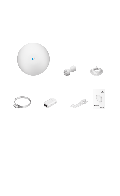
Package Contents
NanoBeam 5AC Gen 2 Ball Joint
Metal Strap Gigabit PoE (24V, 0.5A)
TERMS OF USE: Ubiquiti radio devices must be professionally installed. Shielded Ethernet
cable and earth grounding must be used as conditions of product warranty. TOUGHCable™ is
designed for outdoor installations. It is the customer’s responsibility to follow local country
regulations, including operation within legal frequency channels, output power, and Dynamic
Frequency Selection (DFS) requirements.
with Mounting Bracket
Mount
Power Cord Quick Start
Lock Ring
airMAX® ac CPE with
Dedicated Management Radio
Model: NBE-5AC-Gen2
Guide
Installation Requirements
The NanoBeam can be mounted on a pole or to a wall. A Metal
Strap (included) is used for pole-mounting. For wall-mounting,
a suitable fastener such as a screw or bolt (not included) is
required.
• Pole-mounting: 7 mm socket wrench or screwdriver
• Wall-mounting: wall fastener (not included)
• Shielded Category 5 (or above) cabling with drain wire
should be used for all wired Ethernet connections and
should be grounded through the AC ground of the PoE.
We recommend that you protect your networks from
harmful outdoor environments and destructive ESD events
with industrial-grade, shielded Ethernet cable from Ubiquiti
Networks. For more details, visit www.ubnt.com/toughcable
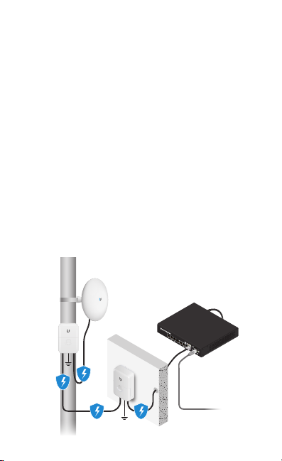
• Surge protection should be used for all outdoor installations.
We recommend that you use two Ethernet Surge Protectors,
model ETH-SP, one near the NanoBeam and the other at the
entry point to the building. The ETH-SP will absorb power
surges and safely discharge them into the ground.
ETH-SP
NBE-5AC-Gen2
ETH-SP
ES-8-150W
To LAN
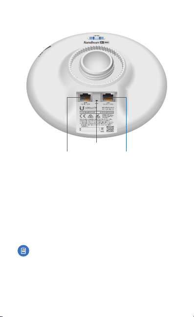
Hardware Overview
Reset Button
Main Ethernet Port
(PoE In)
Main Ethernet Port This Gigabit Ethernet port is used to
connect the power and should be connected to the LAN and
DHCP server. Power can be provided by any of the following:
• Gigabit PoE Adapter (included)
• Ubiquiti Networks TOUGHSwitch™ PoE
• Ubiquiti Networks EdgeSwitch® or EdgeRouter™ PoE
Secondary Ethernet Port This Gigabit Ethernet port provides
passthrough PoE to power and connect a 24V passive PoE
device to the network.
Note: In order to use PoE Passthrough on the Secondary
port, a 24V, 1A PoE adapter is required.
Reset Button To reset to factory defaults, press and hold the
Reset button for more than 10 seconds while the NanoBeam
is poweredon. Alternatively, the NanoBeam may be reset
remotely via a Reset button located on the bottom of the
Gigabit PoE Adapter.
Secondary Ethernet Port
(PoE Passthrough)
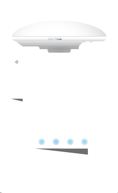
LEDs
Power The Power LED will light blue when the
device is connected to a power source.
Main
Main The LED will light steady blue when an active
Ethernet connection is made to the Main port and
flash when there is activity.
LAN2
LAN2 The LED will light steady blue when an active
Ethernet connection is made to the LAN2 port and
flash when there is activity.
Signal In airOS®, you can modify the threshold
value for the wireless signal strength LEDs on the
Wireless tab under Signal LED Thresholds. Each LED
will light when the wireless signal strength is equal
to or greater than the LED’s threshold value. The
default threshold values for these LEDs are shown
below:
-94 dBm -80 dBm -73 dBm -65 dBm
Hardware Installation
The NanoBeam can be mounted on a pole or to a wall. Perform
the steps for the appropriate installation:
Pole-Mount
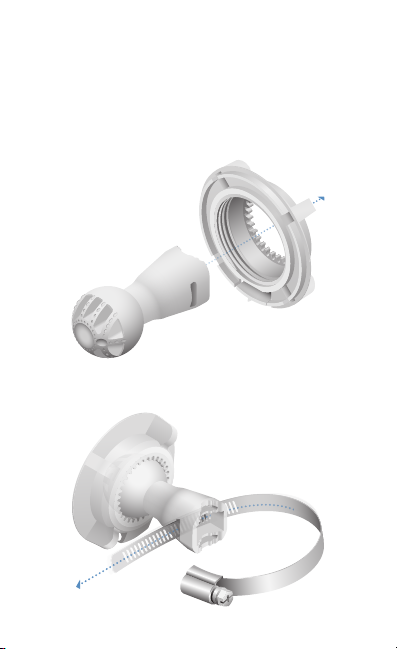
1. Insert the Ball Joint Mount into the Lock Ring with the
threads of the Lock Ring facing the ball joint.
2. Open the Metal Strap and feed it through the base of the
Ball Joint Mount.
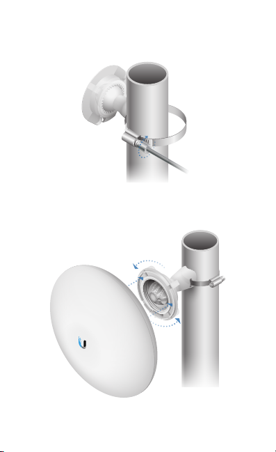
3. Wrap the Metal Strap around the pole. Use a 7 mm socket
wrench to turn the screw clockwise and securely fasten the
clamp to the pole.
4. Attach the NanoBeam to the Ball Joint Mount and turn the
Lock Ring to secure it. Keep the Lock Ring loose enough to
allow the NanoBeam to pivot for aiming.
Wall-Mount
The NanoBeam must be mounted directly to a wood stud
or other structurally stable surface to avoid damage to the
mounting hole when you adjust the aim.
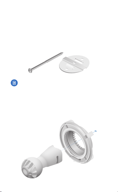
Optional Accessory
To enhance stability, you can use the NanoBeam Wall Mount
Kit, model NBE-WMK (soldseparately).
Note: Center screw included. Two optional screws (not
included) provide additional stability.
Installation Instructions
1. Mark the desired location of the mounting point.
2. If needed, drill a pilot hole for the fastener (not included).
3. Insert the Ball Joint Mount into the Lock Ring with the
threads of the Lock Ring facing the ball joint.

4. If you are using the optional NanoBeam Wall Mount Kit,
then skip to step b.
a. To attach the Ball Joint Mount to the wall, insert a
fastener (not included) through the center of the ball
joint, and into the wall. Securely tighten the fastener.
Proceed to step 5.
b. To attach the Ball Joint Mount to the wall, insert the Wall
Mount Kit screw through the center of the ball joint,
through the Wall Mount Kit plate, and into the wall.
Securely tighten the screw.
 Loading...