

Page 1
1111
Ultra
Ultra
UltraUltra
Tool (900MHz)
Tool (900MHz)
Tool (900MHz)Tool (900MHz)
Kit 0100-2321-01
Case 1 0400-1187-01
Transmitter (900MHz) 2 0100-2320-01
Receiver (900MHz) 1 0100-2319-01
Sense coil 2 0300-2274-01
12' BNC cable 2 0650-0211-01
3' BNC cable 1 0650-0211-02
Antenna (900MHz) 3 3411-0005-01
Bracket 2 0400-1182-01
Battery 1 4007-0004-01
Power cord 2 6003-0007
Ultra•Max detectors and deactivators derive their
timing from the zero crossing of the ac power line.
Ultra•Max detectors and deactivators may interfere
with each other if there are ac line phasing
differences between systems.
The Phasing tool is used to synchronize the timing
of all Ultra•Max systems located in a store,
shopping center, or mall. A reference system is
selected and then all other systems are
synchronized to the reference system.
The basic steps to synchronize all systems are as
follows:
A. Set up a reference transmitter at the
B. Synchronize all other systems within the
C. Use the second transmitter to extend the
Repeat steps B and C until all systems in the
store, shopping center, or mall are
synchronized.
••••
Max Phasing
Max Phasing
Max PhasingMax Phasing
reference system.
range of the reference transmitter.
range of the reference transmitter.
Operating Guide
Before you begin, do the following:
•
Survey the site to identify the location and type
of EAS systems present. Systems that can not
be phased may need to be upgraded.
Upgrading of older equipment should be
planned in advance.
•
Locate all possible sources of 900 MHz
interference including cellular, cordless and
computer equipment. Where possible, avoid
using either the transmitter or the receiver in
those immediate areas. No interference has
been found with wireless equipment but the
presence of such equipment will reduce the
effective range of the Phasing tool.
•
Based on the proximity of the systems to be
phased, choose a starting reference system.
This is often the most difficult part. Choosing
the right reference system can minimize the
amount of phasing required.
Begin with steps A and B and then repeat steps C
and B until all systems are synchronized.
A. Setting up a reference transmitter
A. Setting up a reference transmitter
A. Setting up a reference transmitterA. Setting up a reference transmitter
at the reference system.
at the reference system.
at the reference system.at the reference system.
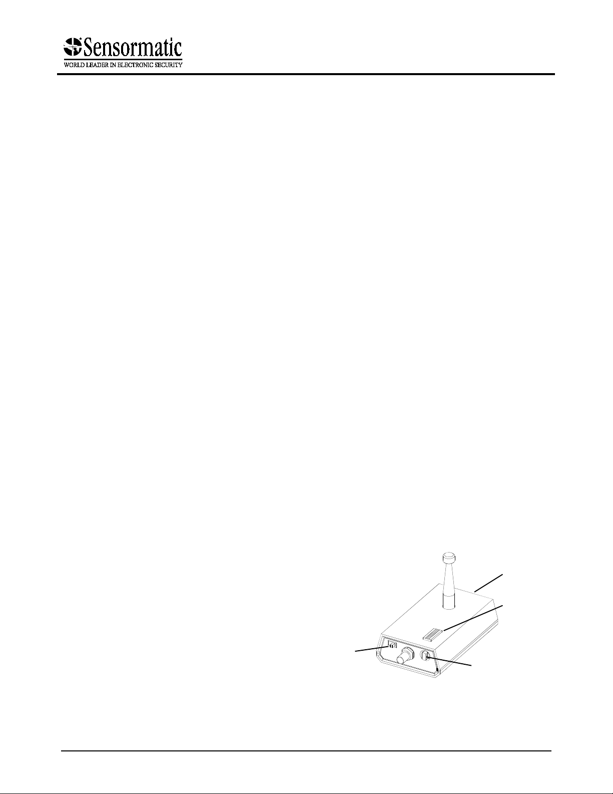
1. Using the receiver, find the channel with
minimal interference.
Power on the receiver and rotate through the 8
available channels (position 0-7 only). Observe
the signal strength indicator and select the
channel with the lowest signal strength.
Figure 1. Receiver
Channels with steady or fluctuating high
Note:
levels of activity will not provide the maximum
range.
Battery
(in back)
Phase all of the systems first! Don't spend a lot of
time tuning systems until all systems have been
phased.
Cover as much area as possible from a single
transmitter location. There will be some error build
up for each time a new transmitter is used.
If you have a team of CE’s with several phasing
tools, you can efficiently phase an entire mall. See
Phasing Team
8000-2574-22, Rev. A (4 pages)
on
page 4
.
Power
on/off
Signal
strength
Channel
selector
ULTRA•MAX PRODUCTS 1
Page 2
)
A
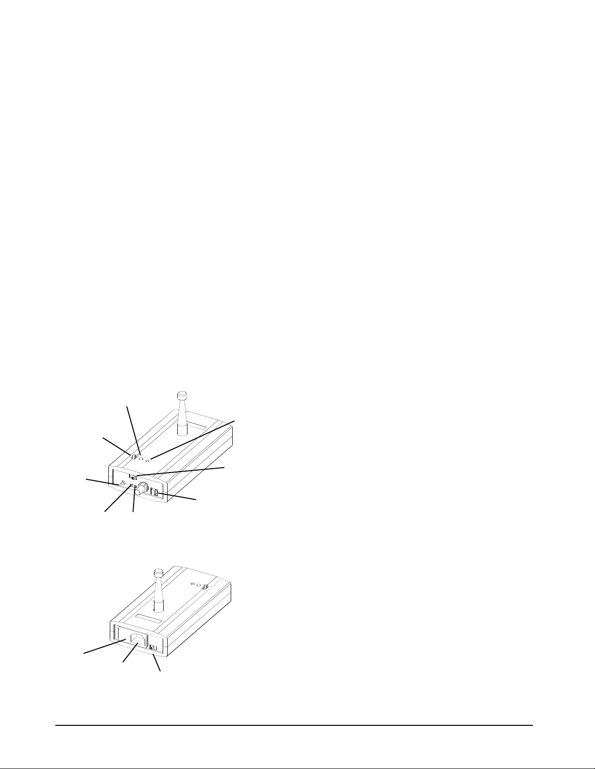
2. Set up the transmitter.
a. Set the first transmitter to the same channel
as the receiver.
b. Locate a power outlet at or near the
reference system and plug in the first
transmitter.
CAUTION:
Make sure the power select fuse on
both transmitters is set for the correct ac
voltage. To change the setting, use the
blade of a small scewdriver to pry out the
power select module. Rotate and insert the
module so that the correct voltage (115,
125, 230, 250) is opposite the arrow.
Locate the transmitter in a clear and open area
that will provide the best possible line of site
to all of the systems to be phased.
Avoid locating the transmitter in the
Note:
ceiling or any metal enclosed areas.
c. Set the switches of the transmitter to
Normal mode
and
ABC Signal
.
Figure 2. Transmitter
Transmit enable
indicator
(on = enabled)
Transmit
enable/
disable
Mode select
SW:
Normal/Test/
External
Power
select
fuse
Coarse
adjust
Power
cord
Fine
adjust
Sync on
°°°°
°°°°
0
/180
ABC signal/
0 crossing
Channel
select
Power
on LED
3. Verify receiver operation.
a. On the receiver's signal strength indicator,
you should see a steady, strong signal.
b. Connect the output of the receiver to
channel 1 of an oscilloscope with the short
BNC cable and the sense coil to channel 2
with the long BNC cable.
c. Verify that channel 1 shows the proper ABC
signal from the transmitter. (One wide,
3ms, negative going pulse followed by two
narrow, 1ms, negative going pulses with a
separation of 5.556ms for 60Hz and
6.667ms for 50Hz.) Best viewed at
1ms/division.
4. Align the reference transmitter
a. Beginning at the transmitter antenna of the
reference system, place the sense coil
against or near the transmitter coil. Position
the coil for the strongest possible signal.
The sense coil is a cylindrical coil and is
Note:
very orientation specific. It must be in the
proper orientation for maximum sensitivity.
b. Verify that channel 2 shows the proper
transmitter burst signal.
In general, the reference system should
Note:
be one with
No Delay
. If the system has
been phased, you should consider first
setting it back to the
No Delay
default.
c. While watching the receiver signal and
burst signal on the oscilloscope, adjust the
Phase Adjustment pot on the first
transmitter so that the burst signal starts at
the
Falling Edge
(beginning) of any one of
the three pulses. Use the “180° Flip” switch
if more adjustment range is needed.
In general, you will want to make a
Note:
coarse adjustment with scope at a large
scale (e.g. 500µs or 1ms/division) and then
fine tune the adjustment with the scope at
50µs/division.
Depending on the type of system being
Note:
adjusted, there will be some timing jitter in
the signals displayed. In this case, adjust
the transmitter such that the jitter is divided
equally between leading and lagging.
(Average the variation.)
2 OPERATING GUIDE
PHASING TOOL (900MHZ
8000-2574-22, REV.
Page 3

You are ready to begin phasing other systems
to the reference signal.
The transmitter can attract unwanted
Tip:
attention when placed in a visible area of a mall.
Place a non-metallic item such as a plastic
caution cone over the transmitter to hide it from
view.
3. Set up the second transmitter.
a. Set the second transmitter to the same
channel as the receiver.
b. Switch the second transmitter’s signal
c. Set the switches of the second transmitter
to
Normal mode
and
ABC Signal
.
OFF
.
B. Synchronize systems within the
B. Synchronize systems within the
B. Synchronize systems within theB. Synchronize systems within the
range of the reference transmitter.
range of the reference transmitter.
range of the reference transmitter.range of the reference transmitter.
1. At the next system, place the sense coil at
or near the transmitter antenna.
2. Verify that you are still receiving a clear
ABC signal from the receiver.
3. Align the system to the reference
transmitter.
While watching the receiver signal and the
system burst on the oscilloscope, adjust the
phase of the system so that the burst starts at
the
Falling Edge
three pulses.
4. Attach a sticker to the system indicating the
5. Continue phasing all of the systems within
C. Extend the range of the reference
C. Extend the range of the reference
C. Extend the range of the referenceC. Extend the range of the reference
transmitter.
transmitter.
transmitter.transmitter.
1. Locate a power outlet within the range of
2. Using the receiver, find another channel
Power on the receiver and rotate through the 8
In general, you will want to make a
Note:
coarse adjustment with scope at a large scale
(e.g. 500µs or 1ms/division) and then fine tune
the adjustment with the scope at 50µs/division.
date that it was phased.
range of the first transmitter signal.
the first transmitter’s signal.
with minimal interference.
available channels (position 0-7 only). Observe
the signal strength indicator and select a
channel with low signal strength.
(beginning) of any one of the
4. Using the oscilloscope, align the second
transmitter.
a. Disconnect the sense coil from the BNC
cable.
b. Attach the BNC cable to the second
transmitter and channel 2 of the
oscilloscope.
c. Switch the receiver back to the same
channel as the first transmitter.
5. Verify receiver operation.
Continue phasing systems as described in Step B.
No timing adjustment are required because of the
second transmitter.
Remove the first transmitter and use it as
necessary to extend beyond the range of the last
transmitter location and so on. Each time you
setup a new transmitter, you must realign the new
signal with the current reference signal as done in
step C.
Channel 1 of the oscilloscope is attached
Note:
to the output of the receiver.
d. While watching the first and second
transmitters’ signals on the oscilloscope,
adjust the Phase Adjustment pot on the
second transmitter so that the second
transmitter’s signal starts at the
(beginning) of the first transmitter
Edge
pulse. Use the “180° Flip” switch if more
adjustment range is needed.
In general, you will want to make a
Note:
coarse adjustment with scope at a large
scale (e.g. 500µs or 1ms/division) and then
fine tune the adjustment with the scope at
50µs/division.
a. Turn on the second transmitter’s signal.
b. Switch the receiver channel to the channel
used by the second transmitter and verify
that the receiver signal from the second
transmitter is aligned properly. You can
verify that it is aligned properly by
comparing it with systems phased
previously using the scope and sense coil.
Falling
PHASING TOOL (900MHZ)
8000-2574-22, Rev. A
OPERATING GUIDE 3
Page 4

)
A
Phasing Team:
If you have a team of CE’s with
several transmitters and receivers, you can
efficiently phase an entire mall using the following
approach:
1. Start by identifying your reference system
and set up a transmitter at that site.
Declarations
Declarations
DeclarationsDeclarations
Regulatory Compliance
Regulatory Compliance
Regulatory ComplianceRegulatory Compliance
EMC: ................................47 CFR, Part 15
2. Using the receiver and an oscilloscope,
travel to the edge of the transmitted signal.
3. Place and phase another transmitter where
the signal gets weak. Remember to use a
different channel for each transmitter.
4. Repeat this process until you have a large
area or the entire mall covered.
5. Once all the transmitters are set up, phase
all systems. When phasing a system, set
the receiver to the channel with the
strongest signal strength.
This technique allows CE’s to work independently
and multiple systems can be aligned at the same
time. An average-size mall can be phased in less
than a day.
FCC COMPLIANCE:
15 of the FCC rules for intentional radiators and Class A
digital devices when in stalled and used in accordance with the
instruction manual. Following these rules provides reasonable
protection against harmful interference from equipment
operated in a commercial area. This equipment should not be
installed in a residential area as it can radiate radio frequency
energy that could interfere with rad io communications, a
situation the user would have to fix at their own expense.
EQUIPMENT MODIFICATION CAUTION:
changes or modifications not expressly approved by
Sensormatic Electronics Corporation, the party responsible
for FCC compliance, could void the user's authority to operate
the equipment and could create a hazardous condition.
This equipment complies with Part
Equipment
4 OPERATING GUIDE
PHASING TOOL (900MHZ
8000-2574-22, REV.
 Loading...