

Page 1
WORLD LEADER IN ELECTRONIC SECURITY
Installation Guide
1 ADS Floor•Max
Antennas
Abou t this Guid e
This installation guide explains how to install ADS
Floor•Max antennas. Ot her related docume nts
are:
Planning Guide, 8000- 2693- 01
•
Insta llat ion G uid e , ADS 2 16 Power Pa c k,
•
8000-2693-02
Setup and Service Guide, 8000-2693-xx
•
Reference G uide, 8000-2693-xx
•
Because placement of antenna components
Note:
depends on architect ural a nd customer requirements, your Sensormatic representative will supply
this information separately.
If you need assistan ce...
Call Sensormatic Custo mer Suppor t at :
1-800-543-9740
Limitation of Warranty
Contents
About this Guide................................................1
Limitation of Warranty........................................1
Antenna Overview.............................................2
Installation Requirements...................................3
Installi ng ADS Floor•Max Antennas.................... 7
Connecting Cond uit and Cables....................... 11
Antenna Tuning............................................... 15
Pouring the Concrete.......................................16
Specifications.................................................. 18
Declarations.................................................... 19
PREL IMINARY – 0 1/31/00
Any deviations from the materials or pr ocedures
spec ified herein shall void S ensormatic's war ranty
with the owner/buyer. In no event sha ll Sensormatic be liable for loss or damage caused by the
use of materials or procedures that do not meet
Sensormatic's specificat io ns .
Ultra•Max, Floor•Max, Sensormatic,
logo
are registered trademarks of Sensormatic Electronics
Corporation. Other product names (if any) mentioned herein
may be trademarks or registered trademarks of other
companies.
No part of this guide may be reproduced in any form without
written permission from Sensormatic Electronics Corporation.
© Copyright 2000. All rights reserved.
DOJ 01/00
and the
Sensormatic
8000-2693-04, R ev. A (19 pages)
ULTRA•MAX PRODUCTS 1
Page 2
S
A
Antenna Overview
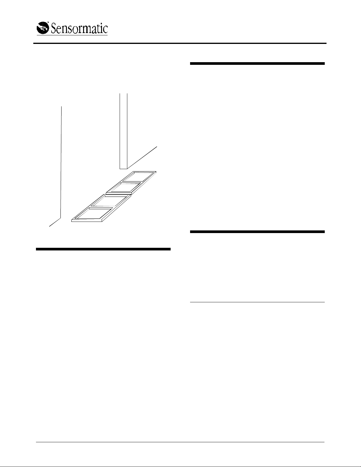
ADS Floor•Max antennas, positioned at an exit,
are part of an Ultra•M ax security label detector that
deters t heft . One or two ADS Floor•Max in-floor
antennas are attac hed to a power pac k through a
capacitor boar d enclosure.
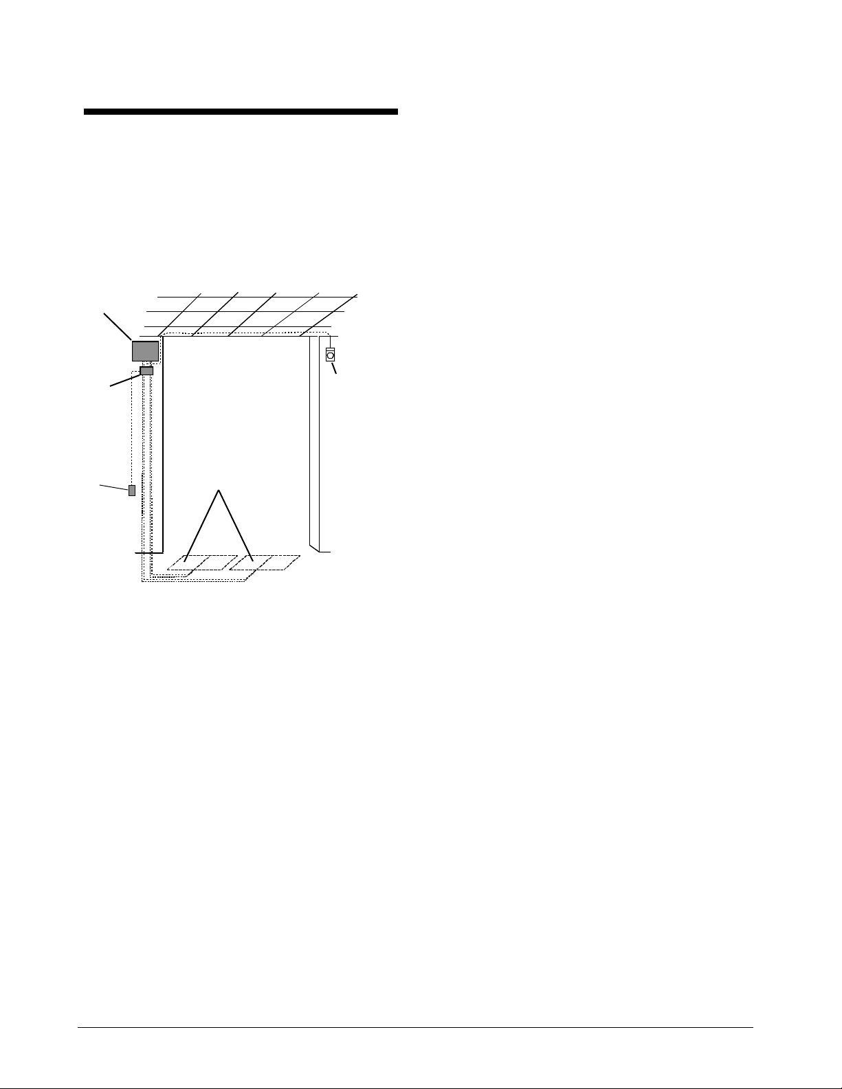
Figure 1. ADS Floor•M ax Det ect or
Component Part Nu mbers
ADS Floor•Max 6' System
1 ADS Floor•Max Ante nna (ZSFLORMX-
−
ANT)
ADS Enc losure Ass e mbly (ZPF LORMX-
−
ENC)
RS232 Assembly (ZPFLO RMX- 232)
−
ADS Power Pack (ZEADS2 16 )
−
Power
pack
Cap board
enclosure
RS232
plate
ADS Floor•Max 12' System
2 ADS Floor•Max Ante nnas (ZSFLORMX-
−
ANT)
ADS Enc losure Ass e mbly (ZPF LORMX-
−
ENC)
Optional
remote
alarm
RS232 Assembly (ZPFLO RMX- 232)
−
ADS Power Pack (ZEADS2 16 )
−
ADS Floor•Max Antenna (ZSFLORMX-ANT)
In-floor
antennas
Install kit (0351-1696- 01)
−
Capacitor board ( 0301- 1536- 01)
−
Antenna (0300-2289-01)
−
ADS Floor•M ax Shield (ZPFLORMX-SH)
Shield tray - left (0300-9219- 01
−
Shield tray - right (0300- 9219- 02)
−
Shield tiles (0500-9216- 01)
−
2 INSTALLATION GUIDE
ADS FLO OR•MAX ANTENNA
8000-2693-04, REV.
Page 3
In st allation Requiremen ts
Verifying Equipment and Unpacking
Verify that all equipment has arri ved. Mak e
❑
sure the system configuration is the right one
for the installation site.
Unpack major components i n a back room. At
❑
the install site, lay out parts in the order you will
need them. Do not clutter the aisle or cause a
trip hazard.
The capacitor board is in a cardboard
Note:
sleeve taped to t he bottom of the ante nna
shipping box. The PVC leveli ng legs are inside
one of the cardboard support r ibs on the end of
the box.
Installer/Contractor
Shall have electrical work comply with the
❑
latest national electr ical code, national f ire
code, and all applicable local codes and
ordinances.
Shall coordi nate all work with other trades to
❑
avoid interfer ence.
Shall verify existing site conditions and
❑
coordinate w ith the owner’s representative and
appropriate utilit ies as requir ed.
Shall obtain copies of all related pla ns,
❑
specificatio ns, shop dr aw ings and addenda to
schedule and coordinate relat ed w or k .
Shall thoroughly re view the project t o ensure
❑
that all work meets or exceeds the above
requirements. Any alleged discrepa ncies shall
be brought to the attentio n of Sensormatic
Electronics.
Chemical Interaction
WARNING!
!
Do not install this product in hazardous
areas where highly combustible or
explosive products are stored or used.
Antenna Placement and Cabling
Whenever possible, keep t he antennas at least
❑
2.4m (8') away from noise sources suc h as
computer monitors, TV’s, switching power
supplies, a nd neon displays.
Maximum cable distance from the antennas to
❑
the capacitor board enclosure is 12.2m (40').
DO NOT splice antenna cables.
Maximum cable dista nce from the power pac k
❑
to the cap board enclosure is 2m (7').
WARNING!
!
DO NOT compromise the structural
integrity of the floor by cutting or removing
rebar. Contractors must obtain approval for
all proposed structural changes. All
structural changes must meet national and
local requirements.
CAUTION:
cost t o the in- floor instal lation, check detector per formance and label detection height at the exact
installation s ite. Do this BEFORE cutting the floor
and again BEFORE pouring the concrete.
❏
Loca te panels i nside the facilit y and as c lo s e to
exit doors as possible.
❏
To provide 1.8m (6') of coverage widt h per
panel, space panels no more than 25-30c m
(10-12") apar t. Spacing of 25cm (10") is
recommended.
❏
For On Grade installatio ns, the pane ls must be
between 3cm (1.25") and 5cm (2") below t he
surface of t he finished floor.
❏
For Off Grade installation, the pa nels must be
1.25cm (.5") below the surface of the finished
floor.
❏
For On Grade installatio ns, no metal such as
rebar or wire mesh should be located under or
adjacent to t he antenna. If metal is required, it
must be spaced great er than 21cm (8") from
the bottom and 31cm (12") in all other
directio ns from the antenna.
❏
For conduit runs, use 3/4-inch Electrical Metal
Tub i ng (EMT) or rigid conduit (
the maximum run not to exceed 10.5m (35') t o
allow adequate cable length for system
connectio ns. Some local codes requir e r igid
conduit instead of EMT for concrete burial.
Some local codes require steel hardwar e in
concrete to be coat ed by tape or paint before
burial.
❏
Use two separ at e conduit runs for each
antenna. Conduit r un must be a minimum of
20cm (8") fr om the antennas. Conduit ca nnot
cross above or below t he antenna. It must be
routed around the perimeter .
To avoid adding sig nificant time a nd
not plastic
) with
ADS FLO OR•MAX ANTENNAS
8000-2693-04, Rev . A
INSTALLATION GUIDE 3
Page 4

S
A
❏
All conduit fittings must be rain/concrete tight. A
3/4-inch EMT fitting is s upplied with the
antenna. A rigid 3/4-i nch rain/concrete tight
fitt ing may be substituted. Wrap t hreads w ith
four turns of Teflon pipe tape.
❏
Minimize underground conduit couplings to
prevent moisture i ntrusion.
❏
Hi gh stre ngth, non-me tallic, non-shrink
mortar/ concret e w it h a compressive strength of
5000 psi is required.(For example, FX- 228
mortar mix and FX-752 bondi ng agent by Fox
Industries)
❏
Mort ar cure time depends on the mix and
temperature of t he mortar ingredients.
❏
Avoid walking on antenna cables duri ng
installation.
❏
Heavy forklifts can pass over the mortar after
24 hours, provided the mortar is protected by
3/4-inch steel plates.
Have on hand tools and equipment necessary
❑
to place the mortar once it is mixed.
Enclosure
❏
Mount the cap board enclosure as close to t he
power pack as possible. M aximum dista nce
from the power pack to the enclosure is 2m (7').
Install a heater in enclosures i n sub-fr eezing
❑
environments.
If conduit is not used, use Romex connectors
❑
wherever cables enter the power pack and
capacitor boar d enclosure.
Tools and Equipmen t Required
For all ADS Floor•Max system inst al latio ns:
6 mil (minimum) plastic sheeting ( t o pr ot ect
•
nearby items from dust)
Chalk or red permanent marker
•
Floor saw
•
PVC pipe cutter or hacksaw
•
Hammer dr ill with 6.5mm (1/ 4" ) and 9. 6 m m
•
(3/8") masonry d rill bit s
Pow er dr ill wit h 1. 6mm ( 1 /16"), 6.5mm (1 /4") ,
•
and 9.6 mm (3/8") d rill bit s
Hammer
•
Phillips and slotted screwdrivers
•
14-16 AWG and 16-22 AWG wire strippers
•
Ratchet a nd socket set
•
Vacuum and broom
•
Wet vacuum
•
Level
•
Electrical tape
•
Teflon pipe tape
•
Caution tape
•
Duct tape
•
4 INSTALLATION GUIDE
ADS FLO OR•MAX ANTENNA
8000-2693-04, REV.
Page 5
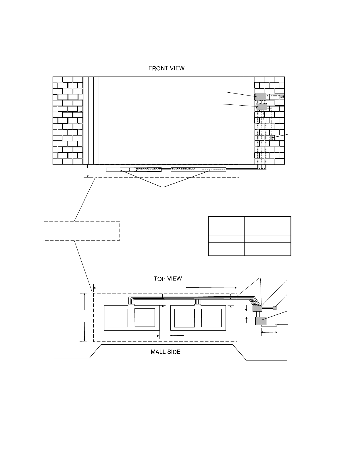
Figure 2. “O n G r ade” inst allation diagr am
25cm (10")
Power pack
Cap board
enclosure
Remote
alarm
RS232
plate
(3cm (1.25") min to 5cm (2") max below surface of floor)
No metal rebar or wire mesh
within 21cm (8") of bottom and
31cm (12") of sides of antenna
1.29m
(4' 3")
Antennas
3.98m (13' 1")
[a]
[c]
No. of
antennas
Length of
excavation
1 2.18m (7' 2")
2 3.98m (13' 1")
3 5.80m (19' 0")
4 7.61m (24' 11")
Conduit run
10.5m (35') max
[a]
[b]
7.5m (25') max
[a] - 20cm (8") min
[b] - 2m (7') max
[c] - 25cm (10")
Cap board
enclosure
RS232
plate
Power
pack
Remote
alarm
ADS FLO OR•MAX ANTENNAS
8000-2693-04, Rev . A
INSTALLATION GUIDE 5
Page 6
S
A
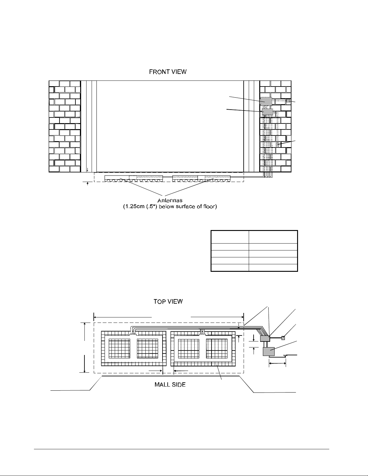
Figure 3. “O f f Gr ade” installation d iagram
5cm (2")
Power pack
Cap board
enclosure
Remote
alarm
RS232
plate
No. of
antennas
Length of
excavation
1 1.91m (6' 3")
2 3.93m (12' 11")
3 5.95m (19' 6")
4 7.96m (26' 2")
Conduit run
10.5m (35') max
Cap board
3.93m (12' 11")
enclosure
RS232
plate
Power
pack
Remote
1.14m
(3' 9")
[a]
[b]
alarm
[c]
7.5m (25') max
[a] - 20cm (8") min
Shield
tiles
[b] - 2m (7') max
[c] - 25cm (10")
6 INSTALLATION GUIDE
ADS FLO OR•MAX ANTENNA
8000-2693-04, REV.
Page 7

In st alling ADS Floor•Max
Antennas
1. Lay out ADS Floor •M ax ant ennas as shown
for proper ant e nna phasing (Figure 4) .
Loca te panels i nside the facilit y and as c lo s e to
exit doors as possible.
DO NOT space antennas more than 25-30c m
(10-12") apar t. Spacing of 25cm (10") is
recommended.
The flat side of the cable entry neck must face
up.
Figure 4. ADS Floor•M ax ant e nna
orientation for pr oper phasin g
Front view of antenna
showing flat side of
neck facing up.
2. Det er mine t he place ment of conduit runs
(Figure 5).
Two separat e conduit r uns ar e r equired f or
each antenna.
Conduit must ter minate at the capacitor
board enclosur e f or pr oper gr ounding.
Figure 5. Antenna w ith conduit att ached
Top view
Ant. 2
CAUTION:
Ant. 1
To avoid adding sig nificant time a nd
cost t o the in- floor instal lation, check detector per formance and label detection height at the exact
installation s ite. Do this BEFORE cutting the floor
and again BEFORE pouring the concrete.
ADS FLO OR•MAX ANTENNAS
8000-2693-04, Rev . A
INSTALLATION GUIDE 7
Page 8

S
A
3. Mark excavation locati on on f loor. Ref er t o
Figure 2 or Figure 3 for r ecommended
length and width of excavat ion.
a. With each antenna in place, use a chalk
line or wide tip red per manent marker to
trace an outline around the outside of t he
antenna and conduit. Also tr ac e the conduit
route from the antenna back to the cap
board enclos ure (Fig ure 6).
b. Remove the antennas.
c. Spray all floor markings with clear lacquer
to prevent erasure during t he floor
excavation process (next).
4. Excavat e t he f loor ( Figure 7) .
a. Usi ng a concret e saw , cut along the
outline.
For “On Grade” installation, cut down to grade.
For “Off Grade” installation, cut to a minimum
depth of 5cm (2").
WARNING!
!
DO NOT compromise the structural
integrity of the floor by cutting or
removing rebar. Contractors must obtain
approval for all proposed structural
changes. All structural changes must
meet national and local requirements.
Figure 6. Mar king the excavat ion lo cat ion
b. Usi ng the specified chipping hammer,
break up the floor and remove the
concrete.
Fiberglass reinfor ced plast ic (FRP) r ebar
Note:
can be used in the excavati on to prevent
cracking and settling. Drill 9/ 16" diameter holes
and dowel the rebar into the sides of the
exca vat ion. Do wels sho u ld be insta lled in the
holes using concrete adhesive. Refer to
Figure 8.
c. Remove all debris fr om the c hannels usi ng
water and a wet vacuum.
Figure 7. Excavatin g t he f loor
8 INSTALLATION GUIDE
ADS FLO OR•MAX ANTENNA
8000-2693-04, REV.
Page 9

Figure 8. FRP rebar instal lat io n
“On Grade” installation
For “Of f G rade” installations, pr oceed t o “Off
Grade” Installati on on page 10
Existing slab
Existing deck
Existing steel beam
31cm
(12")
min
“Off Grade” installation
31cm
(12")
min
25cm
(10")
FRP reinforcing bars
spaced at 31cm (12") on center
25cm
(10")
FRP reinforcing bars
spaced at 31cm (12") on center
Floor•Max
antenna
Floor•Max
antenna
“On Grad e” Installatio n
5. Assemble the antenna suppor t s, if needed.
(Figure 9).
Insert eight support rods into the antenna
support holes in the antenna.
Figure 9. Antenna w it h support rods
Support
rod
6. Level the gr ound under neath t he ant enna
and place the antenna wit h suppor t r ods
into the pit.
The antenna must be a minimum of 3cm (1.25")
and a maximum of 5c m (2") below t he surface
of the finished floor.
Figure 10. Placing supp or t s and assemb ly
31cm (12")
on center
ADS FLO OR•MAX ANTENNAS
8000-2693-04, Rev . A
Top view
31cm
25cm
(12")
(10")
min
INSTALLATION GUIDE 9
Page 10

S
A
7. If necessar y, cut the ant enna suppor t r ods
so that t he ant enna is level (Figure 11).
a. For each support rod, measure the depth of
the excavation from the s urface of the
finished floor.
b. Cut the suppor t r od to t he lengt h of t he
depth of the excavation minus the dept h of
the antenna (3cm (1.25") t o 5cm (2")).
Figure 11. Cutt ing the suppor t r ods
“Off Grade” Installation
5. Smooth the surface in the bottom of the pit.
Remove any peaks or valleys in the bottom of
the pit s o that the tr a y will be s uppor ted firmly.
6. Assemble the tray.
Place the two halves of the tray toget her and
secure with duct tape on the outside of the
bottom of the tray.
Length of rod =
depth of excavation
minus depth of
antenna
Finished floor
Depth of
excavation
Proceed to “Connecti ng Conduit and Cables”
on page 11.
7. Place the tray in the pit.
Orient the tray so that the cutout is on the side
where the cond uit attaches to the antenna.
8. Place ti les on tr ay.
Completely cover the bottom of the tray with
closely packed tiles. Begin placi ng t iles alo ng
the center line of the tray . Work fr om the center
to the outside of the tray. Refer to Figure 12.
9. Place the ant enna on t ile s.
Place the antenna on the tiles so that the
conduit ho using is over the cutout in the tray
and the antenna is centered over the tiles.
Figure 12. Placing til es on t r ay
Center line
10 INSTALLATION GUIDE
ADS FLO OR•MAX ANTENNA
8000-2693-04, REV.
Page 11

Connecting Conduit and
Cables
d. Insert Tx/Rx cable for panel A into
pluggable terminal block Tx/Rx A; insert
transmit cable for panel B into pluggable
terminal block Tx/Rx B.
1. Attach conduit to t he ant enna and pull the
antenna cables ( Figure 5) .
a. Lay out 3/4-inch EMT or rigid conduit from
the antenna to the cap board enclosure.
Two separat e conduit r uns ar e r equired
for each ant enna.
Conduit must ter minate at the capacitor
board enclosur e f or pr oper gr ounding.
b. For DIY installatio ns, lay out conduit from
the power pack t o the capacitor board
enclosure. M aximum conduit r un from the
power pack to the enclosure is 2m (7').
c. Pull t he antenna cables fr om the antenna
to the enclosure.
d. Label the cables indicating the location of
the attached in-floor panel for future
servicing.
e. Attach all conduit and tighten all conduit
connectors. Use only rai n/concrete t ight
EMT or rigid connectors.
f. Ground the conduit t o an earth ground by a
code-approved method suc h as a clamp.
WARNING—RISK OF ELECTRIC
SHOCK!
Failure to ground correctly could cause
shock risk.
2. Connect Tx/ Rx cables (5 conductor ) t o t he
power pack (Figure 15).
WARNING:
the power pack bef or e connecting cables.
a. Install Romex-type connect or s or conduit
fittings in knockouts on pack.
b. Route each Tx/Rx cable through knocko ut.
c. Using a small screw dr iver, attach Tx/Rx
cables to connectors 2109- 0351- 05
accordi ng to the followi ng table:
Do NOT hot plug cables. Turn off
Pin 1 - Black
Pin 2 - Red
Pin 3 - Green
Pin 4 - White
Pin 5 - Shield
3. Connect Com cables (10 conduct or) t o t he
power pack.
a. Route each Com cable through knockout.
b. Usi ng a small screw dr iver, at t ach
connectors 2109-0510-10 to each Com
cable following the color- coded label.
Pin 1 - Black
Pin 2 - Brown
Pin 3 - Red
Pin 4 - Ora nge
Pin 5 - Yellow
Pin 6 - Green
Pin 7 - Blue
Pin 8 - Violet
Pin 9 - Gr ay
Pin 10 - Shield
c. Insert connectors i nto pluggable t er mi nal
blocks on the power pack. Connect panel A
to Com A; connect panel B to Com B.
CAUTION:
cables for a panel are attac hed to
corresponding connectors. Incorrect
connecti ons w ill c ause i nco r rect alarm
signaling.
4. Determine whether the capacitor board
enclosure will be mounted ver t ica lly or
horizontally. Refer t o Figure 13. Identif y
correct knockout locations for ant enna
conduit and connect io n to power pack.
5. Mount cap board enclosure cl ose t o power
pack.
Mount with 3/16" Tapco ns® on masonry wall or
#10 self-t apping screws with anchors o n
drywa l l. Mountin g ha rd ware i s not supp lied.
6. M ount capacit or boar ds in enc losure and
pull cables from pack t o enclosure.
7. M ount RS232 plate and pull cable from
enclosure t o RS232 plate.
The RS232 plate can be mounted on the side
of the cap board enclosure or remotely usi ng a
standard duplex junction box.
Be sure the Tx/Rx and Com
ADS FLO OR•MAX ANTENNAS
8000-2693-04, Rev . A
INSTALLATION GUIDE 11
Page 12

S
A
8. Connect RS2 32 cable to cap boar d and
RS232 plate.
a. Connect the 8 conductor cable to P3 - cap
board A and the 2 conductor cable to P4 cap board B.
b. Cut cable to length leaving sufficie nt slack
to connect to RS232 plate.
c. Remove 6" to 8" of the outer jacket. Strip
all conductors 1/8". Insert shrink tub ing
over drain wire to pr event shorting of
printed circuit board.
d. Connect to connector 2109-0510- 10 in t he
RS232 plate following t he color-coded
label.
Pin 1 - Black
Pin 2 - Brown
Pin 3 - Red
Pin 4 - Ora nge
Pin 5 - Yellow
Pin 6 - Green
Pin 7 - Blue
Pin 8 - Violet
Pin 9 - Gr ay
Pin 10 - Shield
Pin 1 is on t he right end of the connector as
you look at the rear of the RS232 plate.
9. Connect power pack com cable to cap
board.
a. Route cable through knockout.
b. Usi ng a small screw dr iver, at t ach
connectors 2109-0510-10 to each Com
cable following the color- coded label.
Pin 1 - Black
Pin 2 - Brown
Pin 3 - Red
Pin 4 - Ora nge
Pin 5 - Yellow
Pin 6 Green
Pin 7 Bl ue
Pin 8 V iole t
Pin 9 G ray
Pin 10 Shield
c. Insert connectors i nto pluggable t er mi nal
blocks on cap board. Co nnect panel A to
P2 on cap board A; connect panel B to P2
on cap board B.
10. Connect antenna coil cables to cap board.
Use a separate conduit and knockout f or
each coil start and f inish pair (t wo per
antenna). Refer to Figure 15.
a. Route each antenna cable pair thro ugh
knockout and secure away f r om cap board
with cable cla mps located on partition and
sidewall.
b. Attach panel A to TB1-TB4 on cap board A;
attach panel B to TB1-TB4 on cap board B.
Attach using the followi ng table:
TB1 - Bottom coil start ( black)
TB2 - Bottom coil finish (white)
TB3 - Top coil start ( black)
TB4 - Top coil fi nish (white )
CAUTION!
!
For proper operation and reliability,
connect the large diameter, white, coilfinish cables to TB2 and TB4 only.
c. Att ach ground w ires from enclosure
chassis to TB5 on cap boards A and B.
11. Connect power pack T x/ Rx cable to cap
board.
a. Route each Tx/Rx cable through knocko ut
and secure away fr om cap board with cable
clamps located on partitio n and sidewal l.
b. Usi ng a small screw dr iver, at tach Tx/Rx
cables to connectors 2109- 0254- 04
according to the following table:
Pin 1 - Black
Pin 2 - Red
Pin 3 - Green
Pin 4 - White
Pin 5 Shield
c. Insert Tx/Rx cable for pane l A into
pluggable ter minal block P1 o n cap board
A; insert Tx/Rx cable for panel B into
pluggable ter minal block P1 o n cap board
B.
Proceed to “Antenna Tuning” on page 15.
12 INSTALLATION GUIDE
ADS FLO OR•MAX ANTENNA
8000-2693-04, REV.
Page 13

Figure 13. Cap board enclosure
V
ertically mounted
F
B
C
H
E
J
Horizontally mounted
A
C
B
F
H
G
E
I
A
D
I
J
A - Mounting holes
G
B - Power pack Tx/Rx cable entry
C - Power pack Com cable entry
D - Antenna coil cable entry
D
E - RS232 plate mounting location
F - Power pack Tx/Rx and Com cable
entry to other compartment
G - Antenna Tx/Rx cable entry to other
compartment
H - RS232 cable entry to other
compartment
I - Cable supports
J - Ground wire (connect to TB5)
Figure 14. Capacit or boar d 0301- 1536- 01
Tuning jumpers
JW1 – JW7
ADS FLO OR•MAX ANTENNAS
8000-2693-04, Rev . A
TB1 TB2 TB4 TB3
Bottom Bottom Top Top
Start Finish Finish Start
P1 - TB5
Tuning jumpers Tuning jumper LEDS
JW8 – JW14 DS1 – DS7 DS8 – DS14
P4
P2 –
Com
P3
Tx Off Check
LED Tuning button
INSTALLATION GUIDE 13
Page 14

S
A
Figure 15. Wiring d iagram
)
(Cap
)
(Cap
)
(Cap
)
(Cap
)
P8
ADS
Alarm
ADS Power Pack
P2
10 9 8 7 6 5 4 3 2 1
SHLD
GRY
VIO
BLU
P1
SHLD
WHT
GRN
RED
1 2 3 4 5
BLK
P14
RS485
GRN
YEL
P10
Noise
Coil B
ORG
RED
BRN
Noise
Coil A
BLK
Cap Box
P4
P2
P3
A
TB5 TB5
TB3
TB4
P1
TB2
TB1
P17
P9
Option
1
P2
P4 P3
B
TB3
TB4
P1
TB2
TB1
P18
Option
2
P12
Option
3
P11
Ferrite
P13
Relay
A-B
1 2 3 4 5 6 7 8 9 10
BLK
BRN
RED
P4
2 1
SHLD
GRY
P3
8 7 6 5 4 3 2 1
VIO
BLU
GRN
YEL
ORG
RED
BRN
. Board B
P2
. Board B
P7
Tx/Rx
Com
Ped. B
Ped. B
Com
ORG
YEL
GRN
BLU
VIO
GRY
P3
(Cap. Board A)
(Cap. Board B)
1 2 3 4 5 6 7 8 9 10
BLK
BLK
P1
P2
. Board A
P5
P6
Com
Ped. A
SHLD
P4
2109-0510-10
BRN
RED
ORG
YEL
GRN
P1
. Board A
P4
Tx/Rx
Ped. A
Tx/Rx
1 2 3 4 5
BLK
RED
GRN
RS232
Plate
BLU
VIO
GRY
WHT
SHLD
SHLD
Bottom Coil Start
Bottom Coil Finish
To p Coil Start
To p Coil Finish
A
14 INSTALLATION GUIDE
TB1 (Cap. Board A
TB2 (Cap . Boa rd A)
TB3 (Cap . Boa rd A)
TB4 (Cap . Boa rd A)
Floor•
Max
Bottom Coil Start
Bottom Coil Finish
To p Coil Start
To p Coil Finish
Floor•
B
Max
TB1 (Cap . Boa rd B)
TB2 (Cap . Boa rd B)
TB3 (Cap . Boa rd B)
TB4 (Cap . Boa rd B)
ADS FLO OR•MAX ANTENNA
8000-2693-04, REV.
Page 15

Antenna Tuning
The antenna is shipped with default settings that
are acceptable f or most installations. However, the
antenna may require tuning to adjust f or conditions
at the installation site.
The antenna is tuned by changing jumper set t ings
on the capacitor boards in the enclos ure. The
power pack assist s tuning by lighting LEDs to
indicate the correct jumper settings.
To tune the antenna, do the following for eac h
antenna:
1. If necessar y, turn off the power pack.
6. Change the ju mpers on t he capacitor board
to the set t ings indicated by the yellow LE Ds
on the capacitor board. Refer t o Figure 14.
WARNING—RISK OF ELECTRIC
SHOCK!
The green Tx Off LED on the capacitor
board must be ON before changing
jumpers. It indicates there are no high
voltages on the board.
If a yellow jumper LED is on, place the
corresponding jumper in the 1-2 position.
If a yellow jumper LED is off, place the
corresponding jumper in the 2-3 position.
2. Access the capacitor boar d i n t he
enclosure.
3. M ake sur e t he jumpers are set t o the
defaults.
JW1 -
JW2 -
JW3 -
JW4 -
JW5 -
JW6 -
JW7 -
JW8 -
JW9 -
JW10 -
JW11 -
JW12 -
JW13 -
JW14 -
7. Pr ess t he Check T uning but t on on t he
capacitor board and ret ur n t o st ep 5.
After repeating steps 5 and 6 several times, the
antenna should be tuned with t he green status
LED on continuously. If not, c onta ct
Sensormatic Customer Service.
4. Turn on the power pack.
5. Check the gr een st at us LED on the RS232
plate.
If the green st at us LED is ON continuousl y,
the antenna is tuned.
If the green st at us LED is blinking, the
antenna needs tunin g. Pr oceed t o st ep 6.
ADS FLO OR•MAX ANTENNAS
8000-2693-04, Rev . A
INSTALLATION GUIDE 15
Page 16

S
A
Pouring the Concrete
Figure 16. Adding t he f inal layer
CAUTION:
To avoid adding sig nificant time a nd
cost t o the in- floor instal lation, check detector per formance and label detection height at the exact
installation s ite. Do this BEFORE cutting the floor
and again BEFORE pouring the concrete.
1. Prepare the high-str engt h mort ar mix. FX-
228 by Fox Industries is recom men ded but
not required.
Fox products may be replaced by other mortar
materials as long as they have a compressi ve
strength of 5000 psi and contai n no ferrous
metal. For product specif icat io ns, call Tec hnical
Support.
CAUTION:
Work t ime is greatly reduced at
temperatures abo ve 80°F. Comp lete mort ar
placement w ithin the time specified.
2. Rough up the surface and work mortar int o
the sawed face of t he concr et e to promote
bonding and hand sho vel mort ar ar ound all
support r ods bef or e f illing the rest of th e
pit.
CAUTION:
Bottom of ante nnas must be 100%
supported by mortar— NO VOIDS! Do not lift
antenna assemblies o nce they have been
placed in the mortar.
3. Complete ly fil l the pit with additional
mortar. Apply the final layer by t r oweling it
into place (Figure 16) .
CAUTION:
Use only a small amo unt of water
when trow eling the final top surface to avoid
potential shrinkage cracks. Do not over trow el doi ng so will entra p air or le ave b lis ters in the
mortar.
16 INSTALLATION GUIDE
ADS FLO OR•MAX ANTENNA
8000-2693-04, REV.
Page 17

4. Using a garden sprayer, t hor oughly coat the
surface of t he concr et e with curing
compound (ref er back t o Figure 16) .
Wait five minutes for the compound to set.
5. Protect the installation f or at least 72 hour s.
After the initial set, cover mortar with 1.3cm
(1/2") plyw ood in retail installations and 2cm
(3/4") steel plates in DIY installatio ns.
NOTE:
the installation to warn of potential trip hazards.
After 24 hours
installation can be opened to pedest r ia n traf fic.
After 72 hours
plastic sheeti ng. The floor is now ready for the
desired floor coveri ng (tile, car pet , wood, etc. ).
Figure 17. Protecting the installatio n
Place signs and cautio n tape around
—The wood prot ec t ed
—Remove the steel plate a nd
Use caution tape
on edges of
wood or steel trip
hazard
STOP!
Wai t at least 24 hour s before
allowi n g fo rklift tr affic o ver the
steel plates.
Wai t 72 hour s before removing
the plates.
ADS FLO OR•MAX ANTENNAS
8000-2693-04, Rev . A
INSTALLATION GUIDE 17
Page 18

S
A
Specifications
Electrical
Power Supply (Non-European Power Pack)
Primary Input: ...................100-120Vac or
220-240Vac
@ 50–60Hz
Primary Power Fuse:.........5A, 250V slo-blow
Current Draw:...................2.0A peak
Input Power:.....................<180W
Transmitter
Outputs:............................2 ports (two antennas,
multiplexed)
Operating Frequency:........58 or 60kHz (±200Hz)
Transmit Burst Duration.....1.6ms
Transmit Current: ..............16A peak
Burst Repetition Rate:
Based on 50Hz ac.............37.5Hz (Normal)
75 Hz ( Va lidatio n)
Based on 60Hz ac.............45Hz (Normal)
90 Hz ( Va lidatio n)
Environmental
Amb ient Temperature:.......0°C to 50°C
(32°F to 122° F)
Relative Humi dity:............. 0 to 90%
non-condensing
Mechanical
ADS Floor•Ma x Pane l
Length..............................156cm (61 ¼")
Width................................67cm (26 ½")
Depth...............................2cm (.9")
Weig ht..............................kg (lbs.)
Antenna Shield
Length..............................180cm (71")
Width................................91cm (36")
Depth...............................3cm (1.3")
Weig ht..............................kg (lbs.)
Capacitor Board Enclosure
Length..............................47.5cm (18.7")
Width................................37.8cm (14.9")
Depth...............................8.5cm (3.3")
Weig ht..............................kg (lbs.)
Receiver
Inputs:..............................2 ports (two antennas,
multiplexed)
Center Frequency:.............58 or 60kHz
Receive Coil Resistance:...1.6 ohms (±5%)
Alarm
Alarm Relay Output...........DPDT contacts
Contact Switching Current .1.0A max.
Contact Sw itching Voltage .28V max.
Lamp/Audio Duration.........1–30 sec.
(1 sec. increments)
RS232 Plate
Height .............................. 11.5cm (4.5")
Width................................7cm (2.7")
Depth...............................1.7cm (.7")
Weig ht..............................kg (lbs.)
18 INSTALLATION GUIDE
ADS FLO OR•MAX ANTENNA
8000-2693-04, REV.
Page 19

Declarations
Regulatory Compliance (NonEuropean Power Pack)
Safety:............................UL 1950
Can/ CSA C22.2
No. 950
EMC:..............................47 CFR, Part 15
FCC COMPLIANCE:
15 of the FCC rules for intentional radiators and Class A
digital devices when installed and used in accordance with the
instruction manual. Following these rules provides reasonable
protection against harmful interference from equipment
operated in a commercial area. T his equipment should not be
installed in a residential area as it can radiate radio frequency
energy that could interfere with radio communications, a
situation the user would have to fix at their own expense.
EQUIPMENT MODIFICATION CAUTION:
changes or modifications not expressly approved by
Sensormatic Electronics Corporation, the party responsible for
FCC compliance, could void the user's authority to operate the
equipment and could create a hazardous condition.
This equipment complies with Part
Equipment
Other Declarations
WARRANTY DISCLAIMER:
Corporation makes no representation or warranty with respect
to the contents hereof and specifically disclaims any implied
warranties of merchantability or fitness for any particular
purpose. Further, Sensormatic Electronics Corporation
reserves the right to revise this publication and make changes
from time to time in the content hereof without obligation of
Sensormatic Electronics Corporation to notify any person of
such revision or changes.
LIMITED RIGHTS NOTICE:
of Defense, all documentation and manuals were developed at
private expense and no part of it was developed using
Government Funds. The restrictions governing the use and
disclosure of technical data marked with this legend are set
forth in the definition of "limited rights" in paragraph (a) (15)
of the clause of DFARS 252. 227.7013. Unpublished - rights
reserved under the Copyright Laws of the United States.
Sensormatic Electronics
For units of the Department
ADS FLO OR•MAX ANTENNAS
8000-2693-04, Rev . A
INSTALLATION GUIDE 19
 Loading...