

Page 1
© 2018 Sensormatic Electronics, LLC
Do not discard!
This document may be required by code inspectors.
Leave it at the site until the installation is complete
and the system has been approved.
Ultra 1.5 meter ABS Pedestal System®
Installation Guide
ULTRA 1.5 METER ABS PEDESTAL SYSTEM 8200-1048-06, REV. A
INSTALLATION GUIDE
1 of 44 *8200-1048-06*
ZS1146-P, ZS1146-S, ZA1146-D
Page 2

Contents
About this guide ............................................................................................................................................... 3
About the Ultra 1.5 meter ABS Pedestal System .......................................................................................... 3
Kit parts ......................................................................................................................................................... 4
Supported configurations .............................................................................................................................. 5
Coverage distances ...................................................................................................................................... 5
Compatibility .................................................................................................................................................. 5
Safety ............................................................................................................................................................ 6
Installation overview ........................................................................................................................................ 8
Section I: Before you begin ............................................................................................................................. 9
Planning the location of system components ................................................................................................ 9
Installation requirements ............................................................................................................................. 10
System requirements .................................................................................................................................. 11
Section II: Installation .................................................................................................................................... 12
Overview of installation steps ...................................................................................................................... 12
Step 1: Removing the pedestal covers ....................................................................................................... 12
Step 2: Positioning the pedestals ................................................................................................................ 12
Step 3: Routing the cables .......................................................................................................................... 13
Step 4: Securing the pedestal to the floor ................................................................................................... 14
Section III: Connecting the Ultra 1.5m ABS Pedestal ................................................................................. 15
Overview of connection steps ..................................................................................................................... 15
Step 1: Connecting the primary pedestal .................................................................................................... 15
Step 2: Connecting the secondary pedestal ............................................................................................... 17
Step 3: Connecting AC power ..................................................................................................................... 18
Step 4: Tuning the Ultra 1.5 meter ABS Pedestal System ......................................................................... 22
Step 5: Checking EAS performance ........................................................................................................... 28
Step 6: Adjusting the audio alarm ............................................................................................................... 28
Step 7: Installing the pedestal covers ......................................................................................................... 28
Step 8: Covering the antenna cables .......................................................................................................... 29
Step 9: Applying anti-theft labels in other languages .................................................................................. 29
Step 10: Cleaning the pedestal ................................................................................................................... 29
Field replaceable units................................................................................................................................... 30
Boot Loader Mode .......................................................................................................................................... 30
Specifications ................................................................................................................................................. 32
Declarations .................................................................................................................................................... 33
Appendix A: Dimensions ............................................................................................................................... 34
Appendix B: Connecting an Auxiliary Receiver .......................................................................................... 35
Appendix C: Connecting an UltraLink ......................................................................................................... 36
Appendix D: Connecting a Local Device Manager ..................................................................................... 39
Appendix E: Connecting a Digital Remote Alarm ....................................................................................... 41
Appendix F: Main board pinouts .................................................................................................................. 44
ULTRA 1.5 METER ABS PEDESTAL SYSTEM 8200-1048-06, REV. A
INSTALLATION GUIDE
2 of 44 *8200-1048-06*
Page 3
About this guide
This installation guide explains how to install the Ultra 1.5 meter ABS Pedestal System. You must install the
Ultra 1.5 meter ABS Pedestal System as outlined in this guide. Other related documents that can help you with
this installation, include the following:
• CBC-4055 Local Device Manager Installation Guide, 8200-0858-01
• CBC-4020 UltraLink Indoor Installation and Service Guide, 8200-0172-01
• AMC-1060 Digital Remote Alarm Installation Guide, 8200-0505-01
Customer requirements dictate the placement of system components. Your Sensormatic representative
supplies this information separately.
Regulatory restriction: For indoor use only.
Intended use: Only install this device as described in this guide.
If this product was installed in a European Union or European Free Trade Association member state, give the
Declaration of Conform it y included with this pr oduc t to the manager or user . By law, you must provide this
information to the user.
Technical support
For product bulletins, and the most recent updates to this document, visit https://sensormaticsecurelogin.com.
About the Ultra 1.5 meter ABS Pedestal System
The Ultra 1.5 meter ABS Pedestal System described in this document activates an alarm when it detects the
unique response of an active Ultra•Max
The Ultra 1.5 meter ABS Pedestal System consists of two pedestal antennas, a primary and a secondary,
connected by an interconnect cable. The primary pedestal connects to a power source and has an alarm board
and the main controller board. The secondary pedestal does not have a LED alarm indicator; it has the lens
cover and contains a receiver board.
Product features
The Ultra 1.5 meter ABS Pedestal System is similar to the Ultra•Shield systems, but the system has the
following additional features:
• An aesthetic look that meets and exceeds competitive offerings.
• Supports single and dual configurations.
• Integrated audio and visual alarming in the primary pedestal.
• Jammer detection.
• Tags-too-close.
• Network connectivity through the use of a Local Device Manager (LDM).
• The system has a single door coverage capability of 0.9 meters or 3 feet, and a double door coverage
capability of 1.5 meters, or 5 feet.
®
hard tag or disposable label.
ULTRA 1.5 METER ABS PEDESTAL SYSTEM 8200-1048-06, REV. A
INSTALLATION GUIDE
3 of 44 *8200-1048-06*
Page 4
Kit parts
Kit
Product code
Quantity required
Primary pedestal assembly with cover
0304-3039-01
1
Pedestal mounting installation kit
0352-0781-01
1
Kit
Product code
Quantity required
Secondary pedestal assembly with cover
0304-3040-01
1
Pedestal mounting installation kit
0352-0781-01
1
Part
Part number
Quantity required
Washer flat
2848-0025-01
4
Anchors expansion, 5/16” x 1-3/4”
2880-0105-01
4
Bolt, lag, 5/16“ x 2.5“, 1/2" Hex
2880-0106-01
4
Screws, Hex, M6 x 60
5801-4174-520
2
Washer, flat, M8
5840-0700-020
2
Item
Part number
Quantity required
Cable Assembly, transceiver
0652-0789-01
1
Item
Part number
Quantity required
Cable Assembly, transceiver
0652-0789-02
1
Item
Part number
Quantity
Cable Assembly, transceiver
0652-0789-03
1
This section outlines the components you require to install the Ultra 1.5 meter ABS Pedestal System.
Ultra 1.5 meter ABS Pedestal System
Table 1 lists the kit parts you require to install the Ultra 1.5m ABS Single Pedestal S ystem , ZS11 46-P.
Table 2 lists the kit parts you require to install the Ultra 1.5m ABS Secondary Pedestal System, ZS1146-S.
Table 3 lists the kit parts you require to mount the Ultra 1.5 meter ABS Pedestal System.
Table 1. Ultra 1.5m ABS Single Pedestal System, ZS1146-P
Table 2. Ultra 1.5m ABS Secondary Pedestal System, ZS1146-S
Table 3. Pedestal Mounting Installation Kit, 0352-0781-01
Interconnect cable options for the Ultra 1.5 meter ABS Pedestal System
Interconnect cables connect the primary and the secondar y pedestal .
Table 4 lists the kit parts you require to install the 4 meter interconnect cable.
Table 5 lists the kit parts you require to install the 12 meter interconnect cable.
Table 6 lists the kit parts you require to install the 15 meter interconnect cable.
Table 4. AMS-1146 4M TX Interconnect Cable Installation Kit, 0352-0792-01
Table 5. AMS-1146 12M TX Interconnect Cable Installation Kit, 0352-0793-01
Table 6. AMS-1146 15M TX Interconnect Cable Installation Kit, 0352-0794-01
ULTRA 1.5 METER ABS PEDESTAL SYSTEM 8200-1048-06, REV. A
INSTALLATION GUIDE
4 of 44 *8200-1048-06*
Page 5
Supported configurations
Ultra 1.5 meter ABS Pedestal System configuration
Exit coverage distance
Single
0.9 meters, or 3 feet
Dual alternating
1.5 meters, or 5 feet
The Ultra 1.5 meter ABS Pedestal System supports single and dual configurations.
Coverage distances
Table 7 lists the exit coverage capabilities of the Ultra 1.5 meter ABS Pedestal System.
Table 7. Ultra 1.5 meter ABS Pedestal System exit coverage capabilities
Compatibility
The Ultra 1.5 meter ABS Pedestal System is compatible with the following products:
• Ranger Antennas
• Satellite Antennas
• Amorphous Core Receiver
Note: Compatible with one Amorphous Core Receiver only, not a pair of receivers.
• Digital Remote Alarm (DRA)
• Ultra Link
• Local Device Manager (LDM)
• Wireless Device Manager (BIM1000) and the Wireless Device Module (BIX1000)
ULTRA 1.5 METER ABS PEDESTAL SYSTEM 8200-1048-06, REV. A
INSTALLATION GUIDE
5 of 44 *8200-1048-06*
Page 6
Safety
WARNING:
15A or 20A, 2 pole, gange
protection and has a minimum 3 millimeter open circuit clearance, must be installed by a licensed
electrician at a location readily accessible to the equipment.
For installations in other
the primary electrical supply input of the equipment, must be already provided or installed by a
qualified electrician. The National Electric Codes, regulations, cable, and fusi
applicable for the equipment and type of installation must be followed at all times.
Installation require m e nt s
Intended use: Only install this device as described in this guide.
The installer or contractor must adhere to the following criteria:
• Have electrical work comply with the latest national electrical code, national fire code, and all applicable
local codes and ordinances. National or local wiring codes or rules can differ between regions. Adherence
to these codes supersedes instructions in this document.
• Coordinate all work with other trades to avoid interference.
• Verify existing site conditions and coordinate with the owner’s representative and appropriate utilities as
required.
• Obtain copies of all related plans, specifications, shop drawings and addenda to schedule and coordinate
related work.
• Thoroughly review the project to ensure that all work meets or exceeds the above requirements. The
installer or contractor must bring any alleged discrepancies to the attention of Sensormatic Electronics.
Chemical interaction
WARNING: Do not install this product in hazardous areas where highly combustible or explosive
products are stored or used.
Cabling
WARNING: Risk of electric shock
During installation, if the antenna must be left unattended, turn off power or cover high voltage
components to prevent unauthorized access to hazardous voltages.
WARNING: Risk of electric shock
The AC power could be carrying 120Vac or 240Vac.
WARNING: Risk of electric shock
The transmit pedestal contains hazardous voltages. If the pedestal must be left unattended with its
high voltage components exposed, turn off power or cover these components to avoid unauthorized
persons access to hazardous voltages.
WARNING: Do not run the power and comm cables in the same conduit or raceway. Building codes
require that power wiring be separated from other types of wiring.
In accordance with the USA National Electric Code and applicable US local codes, a
d disconnect device, which also provides short circuit and overload
countries, an electrical out let, s uitab le for the vol tag e and current used in
ng requirements
ULTRA 1.5 METER ABS PEDESTAL SYSTEM 8200-1048-06, REV. A
INSTALLATION GUIDE
6 of 44 *8200-1048-06*
Page 7
CAUTION: The AC source must be a two-wire plus ground, 24-hour, unswitched outlet with less than
0.5Vac between neutral and ground.
CAUTION: For permanently connected equipment, a 15A or 20A, two-pole, ganged disconnect device,
which also provides short circuit and overload protection, and has a minimum 3 millimeter open circuit
clearance, in accordance with the National Electric Code and applicable local codes must be installed
by a licensed electrician at a location readily accessible to the equipment.
CAUTION: For pluggable equipment, the socket-outlet shall be installed near the
equipment and shall
be easily accessible.
Important:
• Do not share the AC source with neon signs, motors, computers, cash registers, terminals, or data
communications equipm ent .
• Do not use orange-colored outlets dedicated for computer equipment.
CAUTION: For continued protection against risk of fire, replace fuse only with same type and rating.
Implanted medical devices
This anti-theft system complies with all applicable safety standards. However, people with implanted electronic
medical devices can ask if the store has an anti-theft system, and its location. Although most anti-theft systems
are easily seen, some can be concealed. To help individuals with implanted medical devices, consider the
following health and safety guidelines:
Health and safety
Place the anti-theft system antennas to ensure customers behave in the following ways:
• Do not linger near, or lean on them while making their purchase.
• Are only near the front of them while exiting the checkout area.
For exit systems, place anti-theft system antennas:
• Close to exit and entrance doors, encouraging the customer to pass through them. Do not use antennas
intended for exits in an aisle configuration.
• Away from fixtures, equipment, amusements, and other signage that can attract customers to them.
Apply ‘Anti-theft’ signage
• ‘Anti-theft’ labels ar e place d on each antenna, including those hidden behind door frames and other
structures. Do not cover these labels with other signage.
• In non-English speaking countries, apply ‘Anti-theft’ labels in the local language to the antennas. For hidden
antennas, apply an ‘Anti-theft’ label in the local language to each side of the door frame facing the doorway
about 1.2 meters or 4 feet above the floor. You can order local language labels, 2412-0170-XX, from your
distribution center.
• To improve customer awareness of the anti-theft system, encourage the store to display signs that state it
has an anti-theft system. You can order awareness materials through your sales representative.
ULTRA 1.5 METER ABS PEDESTAL SYSTEM 8200-1048-06, REV. A
INSTALLATION GUIDE
7 of 44 *8200-1048-06*
Page 8
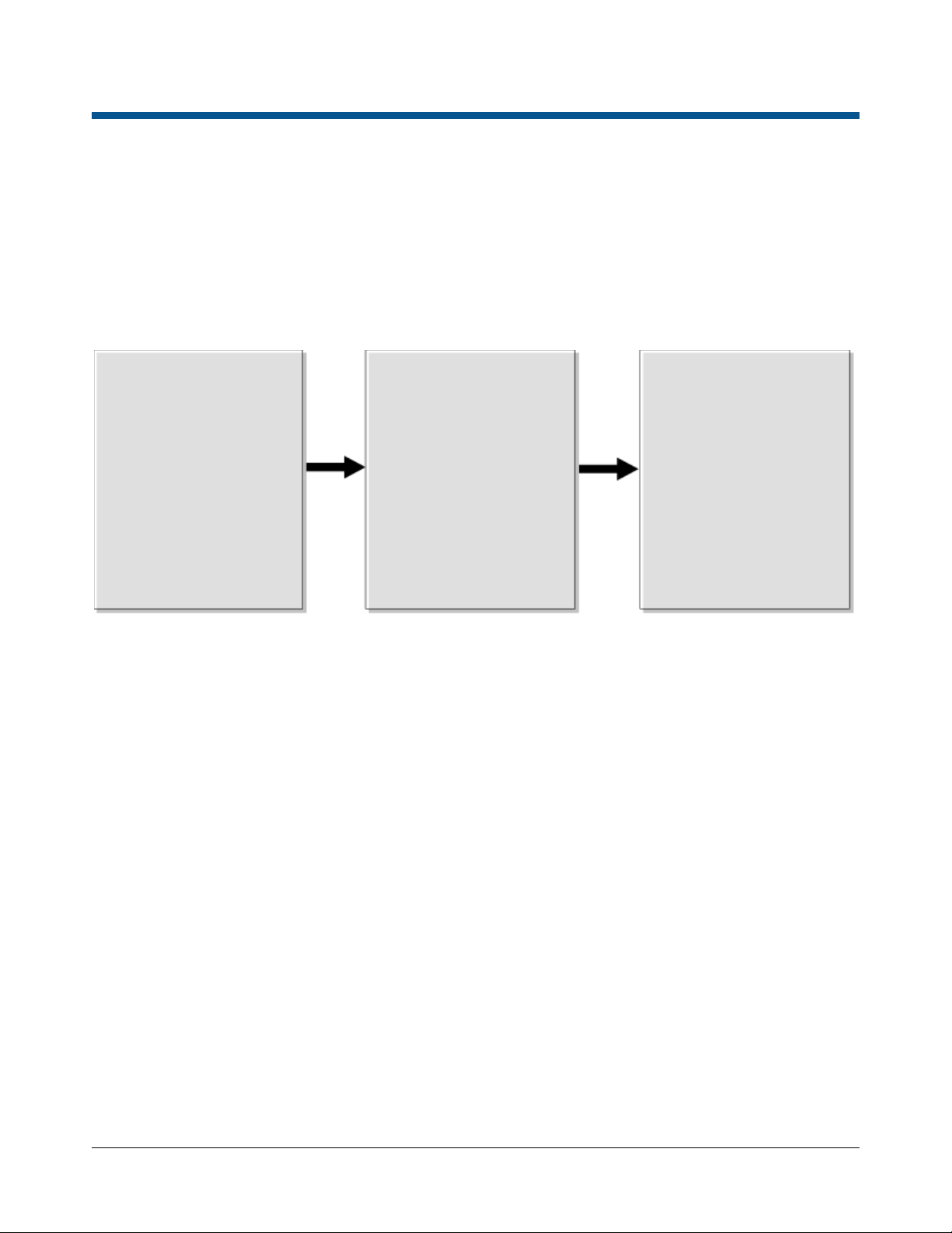
Installation overview
Section I:
Section II:
Section III:
Complete all the
Install the system
Connect the Ultra 1.5
Figure 1 gives an overview of the installation sequence you must follow when installing the Ultra 1.5 meter
ABS Pedestal System.
Figure 1. Ultra 1.5 meter ABS Pedestal System installation overview
Before you begin
prerequisites in Section I
before you install the
Ultra 1.5 meter ABS
Pedestal System.
Installation
components for the
Ultra 1.5 meter ABS
Pedestal System.
Connecting the system
meter ABS Pedestal
System
components,
and verify that they
work.
ULTRA 1.5 METER ABS PEDESTAL SYSTEM 8200-1048-06, REV. A
INSTALLATION GUIDE
8 of 44 *8200-1048-06*
Page 9

Section I: Before you begin
This section outlines the criteria you must adhere to when you install the Ultra 1.5 meter ABS Pedestal
System.
Training
Do not attempt to install the Ultra 1.5 meter ABS Pedestal System unless you have completed the Ultra 1.5
meter ABS Pedestal System Training webinar. To schedule a webinar or in class training, contact your regional
training representatives.
Planning the location of system components
This section outlines how to determine the location for the components of the Ultra 1.5 meter ABS Pedestal
System.
Pedestal location
Consider the following criteria when you select the location of the Ultra 1.5 meter ABS Pedestal System:
• Whenever possible, keep the antennas at least 2.4 meters, or 8 feet away from noise sources such as
computer monitors, TVs, switching power supplies, and neon displays.
• Maximum exit coverage of one primary pedestal is 0.9 meters, or 3 feet.
• The pedestals can protect a space 1.5 meters, or 5 feet wide between them , the primary pedestal also
detects 90 centimeters, or 3 feet behind for total exit coverage of 2.4 meters, or 8 feet.
• The maximum distance between the primary and the secondary pedestals is 1.5 meters or 5 feet, measured
from pedestal center to pedestal center. The minimum distance between two pedestals is
0.6 meters or 2 feet, measured center to center.
• If you must route the interconnect cable over the top of the doors, the maximum cable distance between the
pedestals is either 15 meters, or 50 feet, or 12 meters, or 40 feet, depending on which cable option the
pedestal has. You usually route the supplied 4 meter or 13 feet cable in the floor.
• A transmit field is emitted from both sides of the primary pedestal. Unless you are using backfield reduct ion
configuration, keep displays that are tagged at least 1.5 meters or 5 feet, from the pedestal, especially when
using the tag-too-close function.
• You mount the pedestal to the floor using the four anchors in the AMS-1146 Pedestal Mounting Installation
Kit, 0352-0781-01.
• Cable openings in the pedestal base allow for cable entry from underneath the pedestal or from either end
of the pedestal through a cutaway in the base covers.
®
• Cable access can be through conduit or Wiremold
.
AMC-1060 Digital Remote Alarm
If you are using an AMC-1060 Digital Remote Alarm with the Ultra 1.5 meter ABS Pedestal System, consider
the following criteria:
• The Ultra 1.5 meter ABS Pedestal System does not provide power for the AMC-1060 Digital Remote Alarm,
because the system does not provide power, you need a nearby power outlet. If installing an AMC-1060,
confirm the location of the power outlet before you run the wires.
• Plug the 12V DC transformer used to power the alarm, into a 24-hour unswitched outlet.
• The maximum cable distance from the primary pedestal to each remote alarm is about 12.2 meters, or 40
feet.
ULTRA 1.5 METER ABS PEDESTAL SYSTEM 8200-1048-06, REV. A
INSTALLATION GUIDE
9 of 44 *8200-1048-06*
Page 10

Installation requirements
This section outlines the installation requirements you require to install the Ultra 1.5 meter ABS Pedestal
System.
Tool requirements
You require the following tools and equipment to install the Ultr a 1.5 meter ABS Pedestal System:
• 0.15 millimeters or 6 mils minimum plastic sheeting to protect nearby items from dust
• A permanent marker or pencil
• A power drill with 1 cm, or 3/8 inch masonry drill bit
• A hammer
• Phillips and slotted screwdrivers
• A wire stripper
• Pancake conduit or floor saw and floor-fill material
• A ratchet and socket set
• A utility knife
• A level
• A hand vacuum and broom
Equipment requirement s
You require the following equipment to install the Ultra 1.5 meter ABS Pedestal System:
• The Ultra 1.5 meter ABS Pedestal System, ZS1146-P or, ZS1146-S
• The Ultra 1.5 meter ABS Pedestal System Mounting Installation Kit, 0352-0781-01
• One of the following TX Interconnect Cable Interconnect Kits:
o The 4 meter TX Interconnect Cable Interconnect Kit, 0352-0792-01
o The 12 meter TX Interconnect Cable Interconnect Kit, 0352-0793-01
o The 15 meter TX Interconnect Cable Interconnect Kit, 0352-0794-01
• A hard tag, non-deactivatable Ultra•Max tag, or Ultra•Max low energy labels.
• A laptop computer with Windows
• A RS-232 Ultra•Max programming cable
• A USB to RS-232 converter, if required
Note: For more information on the USB to RS232 converter cable for EAS configurator communication, see
the TB150807 USB to RS232 Converter for EAS PDF, available online at https://sensormaticsecurelogin.com
®
7 operating system, Internet Explorer 11, or Mozilla Firefox
Unpacking and checking e quipment
Complete the following checks when unpacking and verifying the equipment:
• Verify that all equipment is included. Ensure the Ultra 1.5m ABS Pedestal configuration is the correct one
for the installation site.
• Unpack the major components in a space where you are not obstructing or causing nuisance to customers.
At the install site, lay out the parts in the order you require them. Do not clutter the aisle, or cause a trip
hazard.
.
ULTRA 1.5 METER ABS PEDESTAL SYSTEM 8200-1048-06, REV. A
INSTALLATION GUIDE
10 of 44 *8200-1048-06*
Page 11

System requirements
This section outlines the system requirements you require to install the Ultra 1.5 meter ABS Pedestal System.
Laptop requirements
You require the following items for your laptop:
• A laptop computer with Windows
Firefox browser installed.
• A USB to RS-232 converter, if required.
• An RS-232 Ultra•Max programming cable.
Firmware requirements
In order to support the installation of the Ultra 1.5 meter ABS Pedestal System, you must download the latest
firmware bundle from https://sensormaticsecurelogin.com/
Table 8 lists the firmware you require to install the Ultra 1.5 meter ABS Pedestal System.
Table 8. Firmware you require to install the Ultra 1.5 meter ABS Pedestal System
Compatible firmware Version
Ultra 1.5 meter ABS Pedestal System firmware Version 1.0014 or higher
CE ADS4 Platform Configurator Version 9.20 Build 16 or higher
®
7 operating system and the latest Internet Explorer, or Mozilla
.
To download the latest configurator, complete the following steps:
1. Open a web browser and launch the https://sensormaticsecurelogin.com/
2. Enter your valid log-in details, and click Login.
3. From the Tech Support menu, select EAS.
4. Select Software Download.
5. From the Technology list, selec t Detectors.
6. Download the latest bundle.
webpage.
ULTRA 1.5 METER ABS PEDESTAL SYSTEM 8200-1048-06, REV. A
INSTALLATION GUIDE
11 of 44 *8200-1048-06*
Page 12
Section II: Installation
WARNING:
15A or 20A, 2 pole, ganged disconnect device, which also provides short circuit and overload
protection and has a minimum 3 millimeter open circui
licensed electrician at a location readily accessible to the equipment.
For installations in other countries, an electrical outlet, suitable for the voltage
in the primary electrical supply input of the
qualified electrician. The National Electric Codes, regulation
applicable for the equipment and type of installation
This section outlines how to install the Ultra 1.5 meter ABS Pedestal System.
Overview of installation steps
The following list outlines the steps you must complete to install the Ultra 1.5 meter ABS Pedestal System.
• Step 1: Remove the pedestal covers
• Step 2: Position the pedestals
• Step 3: Route the cables
• Step 4: Secure the pedestal to the floor
Step 1: Removing the pedestal covers
To remove the pedestal covers from the Ultra 1.5 meter ABS Pedestal System, complete the following
procedure:
1. At the top of the pedestal, squeeze the area below the alarm lens, and gently pull on the lens to remove it
from the cover.
CAUTION: You must remove the alarm lens gently. Using force to remove the lens from the pedestal
cover can cause the lens to break, or damage to the alarm board LED.
2. Loosen the two captive screws securing the pedestal base covers.
3. Gently prize the pedestal covers apart.
4. Remove the pedestal cover and set it aside.
Step 2: Positioning the pedestals
To mark the locations for the Ultra 1.5 meter ABS Pedestal System and position the pedestals, complete the
following steps:
1. Lift the pedestal from the pedestal base, and set it aside.
2. Determine the location of the Ultra 1.5 meter ABS Pedestal System, as described in Pedestal location
on page 9.
3. Note the location of the power source or the conduit stub where you will place the primary pedestal.
4. Position the primary pedestal in its exact mounting location.
In accordance with the USA National Electric Code and applicable US local codes, a
t clearance, must be installed by a
equipment, must be already provided or installed by a
s, cable, and fusing requirements
must be followed at all times.
and current used
ULTRA 1.5 METER ABS PEDESTAL SYSTEM 8200-1048-06, REV. A
INSTALLATION GUIDE
12 of 44 *8200-1048-06*
Page 13
5. Position the secondary pedestal no more than 1.5 meters, or 5 feet from the primary pedestal.
CAUTION: Do not space Ultra 1.5 meter pedestals more than 1.5 meters, or 5 feet apart.
6. Use the pedestal base as a template, and mark the locations for the four mounting holes. For the pedestal’s
footprint dimensions, see Appendix A: Dimensions, on page 34.
7. Optional: If you are burying the interconnect cable in the ground, mark the location of the interconnect cable
entry hole.
8. Remove the pedestals, and using a drill with a 1.25 centimeter or 1/2-inch masonry bit, drill four 7.6
centimeters or 3-inch deep mounting holes in the floor for each base.
Note: If drilling through carpet, to prevent carpet runs, first mark the holes then cut out the carpet plugs
where the holes will be.
Step 3: Routing the cables
To route the cables for the Ultra 1.5 meter ABS Pedestal System, complete the following steps:
WARNING: Risk of electric shock
Disconnect power from the primary pedestal before you proceed.
The AC power line could be carrying 120Vac or 240Vac.
Route cables underneath and around the controller board on the primary pedestal, and the receiver
board on the second pedestal, using the cabling guide on the pedestal chassis to keep them away
from high voltage.
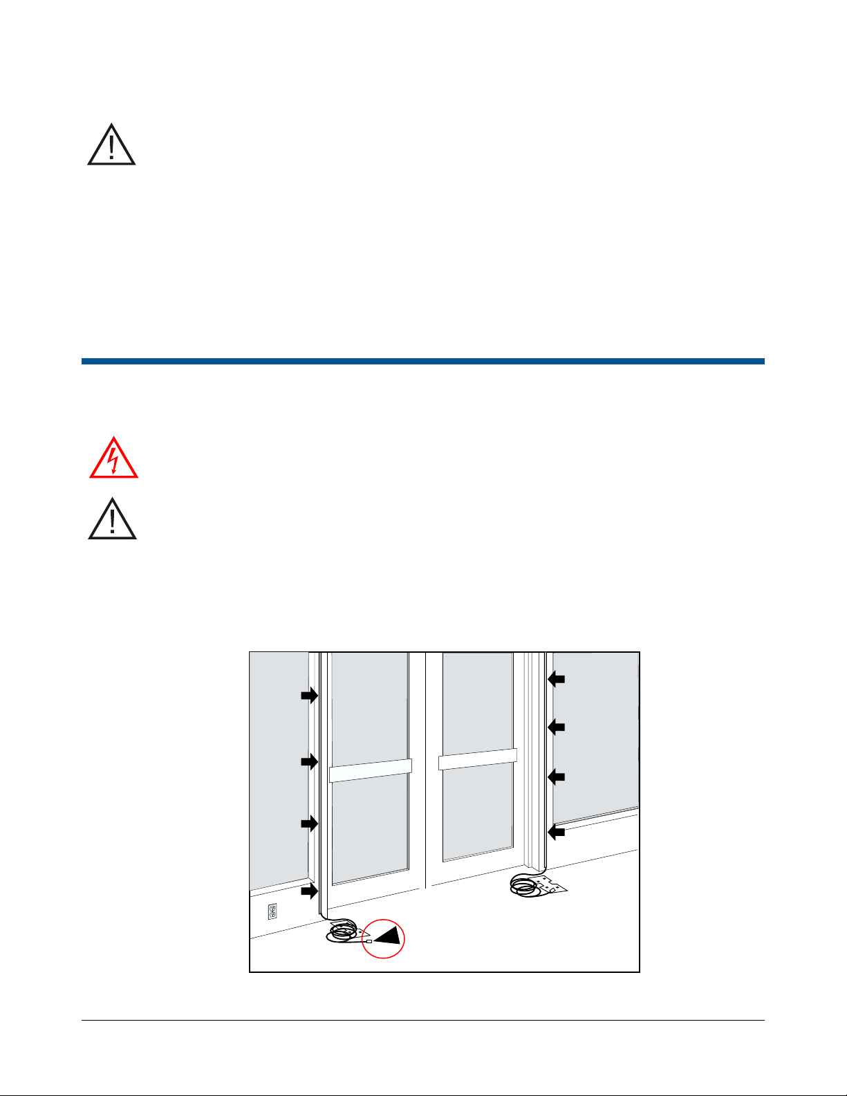
1. Route the cables using the appropriate length of cable: 4 meters or 13.1 feet, 12 meters or 39.3 feet, or 15
meters or 49.2 feet, and then select one of the following options:
• If you are routing the cable over the doorway, route the cable as shown in Figure 2.
Figure 2. Routing the cable over a doorway
ULTRA 1.5 METER ABS PEDESTAL SYSTEM 8200-1048-06, REV. A
INSTALLATION GUIDE
13 of 44 *8200-1048-06*
Page 14
• If you are trenching the floor between the pedestals, ensure the proposed trench extends under the
pedestal location so cables can enter the pedestal from its base underneath. Then, using a floor saw,
trench the floor from pedestal to pedestal. The depth of the trench is 1 centimeter, or 3/8 inches. The
width of the trench is 1 centimeter, or 3/8 inches.
Important: Direct burial without conduit is not permitted in European Union (EU) countries.
2. Note: Skip this step, if you are installing only a single primary pedestal.
Run the interconnect cable between the primary and secondary pedestal and up through the base. The
interconnect cable can enter the base either through the strain-relief on the bottom of the base or from the
center of the side.
3. Route the AC cable to the primary pedestal through the conduit access hole in the base.
WARNING: Do not run the power and interconnect cable in the same conduit or raceway. Building
codes require that power wiring be separated from other types of wiring.
4. If you are installing an optional device, for example, a digital remote alarm or auxiliary receivers, run the
device cable or cables up through the base of the primary pedestal, and along the side of the pedestal
using the cabling guide on the pedestal chassis.
Important: The Ultra 1.5 meter ABS Pedestal System does not provide power for the AMC-1060 Digital
Remote Alarm. Because the system does not provide power, you need a nearby power outlet to support the
required AC adapter. Confirm the location of the power outlet before you run the wires.
Important: The maximum cable distance from the primary pedestal to each remote alarm is about
12.2 meters, or 40 feet.
If you are connecting a digital remote alarm to the system, the wire you use to connect the digital
remote alarm to the pedestal must be shielded, and you must connect the shield wire at both ends.
Step 4: Securing the pedestal to the floor
To secure the Ultra 1.5 meter pedestal to a floor, complete the following steps:
1. Level the pedestal base, or bases.
2. Locate the anchor wedges, 2880-0105-01, from the Pedestal Mounting Installation Kit, 0352-0781-01. Insert
the anchor wedges into the holes in the floor, and tap the anchors into the holes.
3. Place the pedestal over the four protruding anchors in the floor.
4. Secure each pedestal base to the floor using the four screws, 5801-4174-520, and the four anchors, 28800105-01, from the Pedestal mounting installation kit, 0352-0781-01.
5. Locate the pedestal that you previously set side, and slip the pedestal over the pedestal base.
ULTRA 1.5 METER ABS PEDESTAL SYSTEM 8200-1048-06, REV. A
INSTALLATION GUIDE
14 of 44 *8200-1048-06*
Page 15

Section III: Connecting the Ultra 1.5m ABS Pedestal
Pin
Color
Signal name
1
Black
Top coil
2
Red
Top coil return
3
Green
Bottom coil
4
White
Bottom coil return
5
Shield
Shield
This section outlines how to connect the cables and wire the Ultra 1.5 meter ABS Pedestal System.
Overview of connection steps
The following list outlines the steps you must complete to connect and wire the Ultra 1.5 meter ABS Pedestal
System:
• Step 1: Connect the primary pedestal
• Step 2: Connect the secondary pedestal
• Step 3: Connect AC power
• Step 4: Tune the Ultra 1.5 meter ABS Pedestal System
• Step 5: Check EAS performance
• Step 6: Adjusting the audio alarm
• Step 7: Install the pedestal covers
• Step 8: Cover the antenna cables
• Step 9: Apply anti-theft labels in other languages
• Step 10: Clean the pedestal
Step 1: Connecting the primary pedestal
To connect the cables to the controller board of the primary pedestal, complete the following steps:
1. Note: Skip this step, if you are installing only a single primary pedestal.
On the main controller of the primary pedestal, attach the interconnect cable to the 5-position Euro-style
connector which is plugged into connector P6. For the connections, see Table 9 and Figure 3. For the location
of the P6 connector, see Figure 4.
Table 9. Primary pedestal interconnect cable connections
Figure 3. Connecting the interconnect cable
ULTRA 1.5 METER ABS PEDESTAL SYSTEM 8200-1048-06, REV. A
INSTALLATION GUIDE
15 of 44 *8200-1048-06*
Page 16

Figure 4. P6, P5, and top and bottom coil locations on the main controller board
A
Bottom coil connector, P3
C
Connector P5 location
B
Top coil connector, P1
D
Secondary P6
Pin
Color
Signal name
1
Black
Primary top coil return
2
Red
Shield
3
White
Primary top coil
Pin
Color
Signal name
1
Black
Primary top coil return
2
Red
Shield
3
White
Primary top coil
A B C
D
Note: If you are replacing the main board, connect P1, P3 and P5 alarm cable.
2. On the primary pedestal, plug the alarm cable 0652-5812-01, into connector P5 of the controller board.
3. Attach the 3-position connector to the upper antenna coil cable as shown in Table 10. Plug the cable into
the top coil connector, P1, on the controller board.
Table 10. Antenna top coil connections
4. Attach the 3-position connector to the lower antenna coil cable as shown in Table 11. Plug the cable into
the bottom coil connector, P3, on the controller board.
Table 11. Antenna bottom coil connections
ULTRA 1.5 METER ABS PEDESTAL SYSTEM 8200-1048-06, REV. A
INSTALLATION GUIDE
16 of 44 *8200-1048-06*
Page 17

Step 2: Connecting the secondary pedestal
Pin
Color
Signal name
1
Black
Top coil
2
Red
Top coil return
3
Green
Bottom coil
4
White
Bottom coil return
5
Shield
Shield
A
Connector P1 location
C
Connector P3 location
B
Connector P2 location
A
B
C
To connect the cables to the receiver board on the secondary pedestal, complete the following step:
WARNING: Risk of electric shock
Disconnect power from the primary pedestal before you proceed.
• On the receiver board of the secondary pedestal, attach the interconnect cable to the 5-position Euro-
style connector which is plugged into connector P2. For the connections, see Table 12 and Figure 5.
For the location of the P2 connector, see Figure 6.
Table 12. Secondary pedestal receiver cable connections
Figure 5. Connecting the interconnect cable
Figure 6. P1, P2 and P3 locations on the receiver board
ULTRA 1.5 METER ABS PEDESTAL SYSTEM 8200-1048-06, REV. A
INSTALLATION GUIDE
17 of 44 *8200-1048-06*
Page 18

If you are replacing the secondary receiver board, you must complete the following steps:
Pin
Color
Signal name
1
Black
Secondary top coil return
2
Red
Shield
3
White
Secondary top coil
Pin
Color
Signal name
1
Black
Secondary bottom coil return
2
Red
Shield
3
White
Secondary bottom coil
1. Attach the 3-position connector to the upper antenna coil cable as shown in Table 13. Plug the cable into
the top coil connector, P1, on the receiver board.
Table 13. Secondary antenna top coil connections
2. Attach the 3-position connector to the lower antenna coil cable as shown in Table 14. Plug the cable into
the bottom coil connector, P3, on the receiver board.
Table 14. Secondary antenna bottom coil connections
Step 3: Connecting AC power
To connect the system to AC power, complete the following steps:
CAUTION: A 15A, two-pole, ganged disconnect device, which also provides short circuit and overload
protection, and has a minimum 3 millimeter open circuit clearance, in accordance with the National
Electric Code and applicable local codes must be installed by a licensed electrician at a location
readily accessible to the equipment. If the only line providing power is the primary/L1, you can use a
single-pole breaker.
1. Locate the voltage shunt, 2109-0062-01, which is in a bag taped inside the primary pedestal enclosure.
WARNING: Risk of electric shock
Ensure that the system is not powered before moving the shunts.
2. Select the proper voltage for the site using the shunt, 2109-0062-01. The default setting is 240Vac.
For the location of J5, see Figure 8.
Figure 7. Voltage settings and shunts
120 Vac: J5 shunt IN 240 Vac (Default): J5 shunt OUT
ULTRA 1.5 METER ABS PEDESTAL SYSTEM 8200-1048-06, REV. A
INSTALLATION GUIDE
18 of 44 *8200-1048-06*
Page 19

Figure 8. J5 location on the capacitor board
A
J5
A
WARNING: Risk of electric shock
Ensure that the circuit breaker for the power cable is off before connecting the pedestal to AC power.
The AC power cord may carry 120Vac or 240Vac.
CAUTION: You can not use a power cord with the Ultra 1.5 meter ABS Pedestal System.
You must hardwire the system.
3. Connect the pedestal to AC power by hard-wiring the system.
4. Complete the following steps to remove the metal drip plate:
a. Locate the screw securing the drip plate to the pedestal, as shown in Figure 9.
b. Unscrew the screw from the drip plate, and set the drip plate aside for later use.
Figure 9. Metal drip plate screw
ULTRA 1.5 METER ABS PEDESTAL SYSTEM 8200-1048-06, REV. A
INSTALLATION GUIDE
19 of 44 *8200-1048-06*
Page 20

5. Loosen the ground screw, positioned to the right of the power connector. For the location of the ground
A
Line
C
Ground jumper, ground point
B
Neutral
D
Ground screw
C
B
A
D
screw, see Figure 10.
Figure 10. Wiring the power conn ector
6. Route the AC power cord up the right side of the pedestal base.
7. Connect the AC power wires to the power connector on the main controller board. Connect the Line wire
(black) to L, the Neutral wire (white) to N, and the Ground wire (green) to the ground screw on the main
controller board, as shown in Figure 10.
2
Note: The power connector accepts 0.75 to 2.0 mm
(18 to 14 AWG) wire.
Important: If you remove the connector, do not pull it out by the wires; pull on the connector.
8. Tighten the ground screw, and secure the Ground wire (green).
Note: When connecting the ground wire, ensure the slot on the washer is pointing down to allow the jacket
on the cable to fit behind the washer. See Figure 11.
Figure 11. Connecting the Ground wire
WARNING: After tightening the ground wire screw, carefully inspect the ground wire to insure that no
wire strands are touching any components on the board.
ULTRA 1.5 METER ABS PEDESTAL SYSTEM 8200-1048-06, REV. A
INSTALLATION GUIDE
20 of 44 *8200-1048-06*
Page 21

9. Reattach the metal drip plate positioning the wires behind the access slot, as shown in Figure 12.
WARNING: Risk of electric shock
When reattaching the drip plate do not to damage or pinch any cables routed behind it. Ensure the
cables route up through the access slot.
Figure 12. Routing the cables
WARNING: Do not run the power and comm cables in the same conduit or raceway. Building codes
require that power wiring be separated from other types of wiring.
ULTRA 1.5 METER ABS PEDESTAL SYSTEM 8200-1048-06, REV. A
INSTALLATION GUIDE
21 of 44 *8200-1048-06*
Page 22

Step 4: Tuning the Ultra 1.5 meter ABS Pedestal System
The goal of tuning is to adjust the total capacitance on the capacitor board until the current amplitudes in the
top and bottom coils are maximized.
WARNING: Risk of electric shock
High-voltage AC is present on the Cap board whenever the pedestal power is on. Ensure that the
system is not powered before touching the tuning jumpers.
Before you tune the Ultra 1.5 meter ABS Pedestal System
Tuning jumpers are used to adjust the total capacitance of the antennas. The main controller board on the
primary pedestal has two groups of tuning jumpers: JW6-JW8 and JW12 for the top coil, and JW9-JW11 and
JW13 for the bottom coil. The secondary pedestal requires no tuning.
Before applying power to the antenna and tuning the primary pedestal, complete the following steps:
1. Verify the board is properly seated and all cables are securely connected.
2. Ensure the tuning jumpers are in their default tuning positions on the primary pedestal. Se e Table 17 and
Figure 17 on page 27.
Tuning the Ultra 1.5 meter ABS Pedestal System
To tune the Ultra 1.5 meter ABS Pedestal S ystem, complete the following steps:
WARNING: Risk of electric shock
High-voltage AC is present on the Cap board whenever the pedestal power is on. Ensure that the
system is not powered before touching the tuning jumpers.
1. Supply power to the system.
2. Connect your laptop computer to the RS-232 service port, J2, on the primary controller board. For the
location of the J2 service port, see, Appendix F: Main board pinouts on page 44.
3. Launch the CE ADS4 Platform Configurator.
4. Click the TX Configuration tab. See Figure 13, on page 23.
5. In the Misc. TX Settings area, select the following parameters for the antenna:
• Ant Polarity: Aiding
• TX Frequency: Nominal
CAUTION:
Afte r you have finished tuning the pedestal, you must return the Misc. TX Settings to previous values
to return the pedestals to their normal operating modes.
ULTRA 1.5 METER ABS PEDESTAL SYSTEM 8200-1048-06, REV. A
INSTALLATION GUIDE
22 of 44 *8200-1048-06*
Page 23

Figure 13. TX Configuration window
6. Click the Setup tab. From the System Configuration list, select the correct configuration for the site, for
example, Prim Transceiver Only. See Figure 14.
Figure 14. Setup tab location
ULTRA 1.5 METER ABS PEDESTAL SYSTEM 8200-1048-06, REV. A
INSTALLATION GUIDE
23 of 44 *8200-1048-06*
Page 24

7. From the System menu, click TX Current. This window displays transmit current meters for the antennas.
A
Antenna transmit enable checkbox
C
Bottom Coil Aiding meter
B
Top Coil Aiding meter
A
B
C
Figure 15. CE ADS4 Platform Configurator System menu
8. On the TX Current window, observe the Top Coil Aiding and the Bottom Coil Aiding meters as you tune the
current for the highest amplitude. See Figure 16.
Note: The current for the primary pedestal should not exceed 33-40A.
Figure 16. TX Current window meters
ULTRA 1.5 METER ABS PEDESTAL SYSTEM 8200-1048-06, REV. A
INSTALLATION GUIDE
24 of 44 *8200-1048-06*
Page 25

Tuning the primary pedestal
Ultra 1.5 meter ABS Pedestal System
33-40A
The main controller board has two banks of four jumpers: JW6-JW8 and JW12 for the top coil, and JW9-JW11
and JW13 for the bottom coil. Ensure you are looking at the correct jumpers. For the location of the jumpers
see Figure 17, on page 27.
Note: The jumper configurations do not have to be the same. The top coil and bottom coil, can have different
jumper configurations.
Tuning the top coil
To tune the top coil on the primary pedestal, complete the following steps:
WARNING: Risk of electric shock
Before adjusting jumpers, clear the Antenna check box in the configurator to disable the antenna.
After changing the jumper, select the box to re-enable the antenna.
1. From the TX Current window, disable antenna transmission. To disable an antenna transmission, clear the
relating check box.
2. Using Table 17 on page 27, set the top coil tuning jumpers to their default tuning positions.
3. Referring to Table 17, reposition the top coil tuning jumpers, JW6-JW8 and JW12, one step up from their
default positions. Enable antenna transmission to observe the current meters.
4. If the current increased, add capacitance by completing the following steps:
Important: Before adjusting the jumpers in the following steps, you must clear the antenna check box on
the configurator.
a. Disable antenna transmission and reposition the top coil tuning jumpers one more step up.
b. Enable antenna transmission again and observe the meters. If the current increased again, move
another step up in the table.
c. Continue until the current displayed on the meter decreases. Then move one step down and
reconfigure the top coil tuning jumpers to obtain the highest coil current.
Table 15. Target current, top coil
Note: The values of the currents are for a line input of 120Vac and a four meter-long interconnect cable.
5. If current decreased, subtract capacitance by completing the following steps:
Important: Before adjusting the jumpers in the following steps, you must clear the antenna check box on
the configurator.
a. Disable antenna transmission and reposition the top coil tuning jumpers one step down in the tuning
table.
b. Enable antenna transmission again and observe the meters. If the current increases, move another
step down in the table.
c. Continue until the current displayed on the meter decreases. Then move one step up and reconfigure
the top coil tuning jumpers to obtain the highest coil current.
ULTRA 1.5 METER ABS PEDESTAL SYSTEM 8200-1048-06, REV. A
INSTALLATION GUIDE
25 of 44 *8200-1048-06*
Page 26

Tuning the bottom coil
Ultra 1.5 meter ABS Pedestal System
33-40A
To tune the bottom coil of the primary pedestal, complete the following steps:
CAUTION:
After you have finished tuning the pedestal, you must return the Misc. TX Settings to their previous
values to return the pedestals to their normal operating modes.
1. From the TX Current window, disable antenna transmission. To disable an antenna transmission, clear the
relating check box.
2. Using Table 17 on page 27, set the bottom coil tuning jumpers, JW9-JW11 and JW13, to their default tuning
positions.
3. Referring to Table 17, reposition the bottom coil tuning jumpers one step up from their default positions.
Enable antenna transmission to observe the current meters.
4. If the current increased, add capacitance by completing the following steps:
Important: Before adjusting the jumpers in the following steps, you must clear the antenna check box on
the configurator.
a. Disable antenna transmission and reposition the bottom coil tuning jumpers one more step up.
b. Enable antenna transmission again and observe the meters. If the current increases again, move
another step up in the table.
c. Continue until the current displayed on the meter decreases. Then move one step down and
reconfigure the bottom coil tuning jumpers to obtain the highest coil current.
d. When the antenna is properly tuned, return the Misc. TX Settings to their previous values:
• Ant A|B|C|D Polarity: Normal
• TX Frequency: Hopping
Table 16. Target current, bottom coil
Note: The values of the currents are for a line input of 120Vac and a four meter long interconnect cable.
5. If the current decreased, subtract capacitance by completing the following steps:
Important: Before adjusting the jumpers in the following steps, you must clear the antenna check box on
the configurator.
a. Disable antenna transmission and reposition the bottom coil tuning jumpers one step down in the tuning
table.
b. Enable antenna transmission again and observe the meters. If the current increases, move another
step down in the table.
c. Continue until the current displayed on the meter decreases. Then move one step up and reconfigure
the bottom coil tuning jumpers to obtain the highest coil current.
Note: You may have to retune the top coil again. If adjustment is required, disable antenna transmission
and reconfigure the jumpers one column to the left or right in the table as required. Recheck the antenna
current and readjust as required.
d. When the antenna is properly tuned, return the Misc. TX Settings to their previous values:
• Ant A|B|C|D Polarity: Normal
• TX Frequency: Hopping
ULTRA 1.5 METER ABS PEDESTAL SYSTEM 8200-1048-06, REV. A
INSTALLATION GUIDE
26 of 44 *8200-1048-06*
Page 27

Table 17. Primary pedestal tuning table
Coarse Adjust
Med
Fine
Notes
JW12
JW8
JW7
JW6
Top jumpers
JW13
JW11
JW10
JW9
Bottom jumpers
1
Off
Off
Off
Off
Minimum capacitance
2
Off
Off
Off
On 3
Off
Off
On
Off 4
Off
Off
On
On
6
Off
On
Off
On 7
Off
On
On
Off 8
Off
On
On
On
Top coil default
9
On
Off
Off
Off
10
On
Off
Off
On
11
On
Off
On
Off
12
On
Off
On
On
13
On
On
Off
Off
14
On
On
Off
On
Bottom coil default
16
On
On
On
On
Maximum capacitance
A
Bottom coil tuning jumpers
F
JW8
B
JW13
G
JW7
C
JW11
H
JW6
D
JW10
I
JW12
E
JW9
J
Top coil tuning jumpers
B
C D E
F
G
H I J
A
Step
5 Off On Off Off
15 On On On Off
Figure 17. Location of jumpers on the primary pedestal main board
Note: Locate the jumpers at the top of the main controller board, on the primary pedestal.
ULTRA 1.5 METER ABS PEDESTAL SYSTEM 8200-1048-06, REV. A
INSTALLATION GUIDE
27 of 44 *8200-1048-06*
Page 28

Step 5: Checking EAS performance
A
B
B
A
Using a known-good tag, test the performance of the system to ensure it performs satisfactorily.
• If the performance is satisfactory, you do not have to tune the antennas.
• If the performance is not satisfactory, you must retune the antennas. See Step 4: Tuning the Ultra 1.5
meter ABS Pedestal System, on page 22.
Step 6: Adjusting the audio alarm
To adjust the audio alarm from the piezo on the primary pedestal, complete the following step:
• Adjust the potentiometer using a Philips screw driver. For the location of the potentiometer see Figure 18.
Note: The alarm board is located under the lens cap of the primary pedestal.
Figure 18. Locating the potentiometer
Potentiometer
Piezo
Step 7: Installing the pedestal covers
To install the base covers on the Ultra 1.5m ABS Pedestals, complete the following procedure.
WARNING: Risk of electric shock
Disconnect power from the pedestals before you proceed. Components on the circuit board have line
voltage.
1. Disconnect power from the pedestals.
2. Locate the pedestal covers, you previously set aside.
3. Align the pedestal cover to the pedestal, and reattach the cover by snapping it into place.
4. At the top of the pedestal, insert the two captive screws, and then tighten the screws to secure the pedestal
cover.
5. Supply power to the pedestals.
6. Test the system with an active EAS tag or label to verify that the pedestal is operational.
ULTRA 1.5 METER ABS PEDESTAL SYSTEM 8200-1048-06, REV. A
INSTALLATION GUIDE
28 of 44 *8200-1048-06*
Page 29

Step 8: Covering the antenna cables
If the cables were laid in a trench between the pedestals, cover them with a proper fill, such as non-metallic,
non-shrink, 5000-psi mortar or concrete.
• The 4-meter transceiver cable assemblies, 0352-0792-01, use the cable part number 0652-0789-01.
• The 12-meter transceiver cable assemblies, 0352-0793-01, use the cable part number 0652-0789-02.
• The 15-meter transceiver cable assemblies 0352-0794-01, use the cable part number 0652-0789-03.
The following cable has been investigated and found suitable for direct burial in mortar and concrete. An
inspector can request the listing file number for the cable.
Sensormatic part number Listing file numbers* Vendor
6002-0254-01 Rated CL2P E34972 Belden
* The listing file number varies with the cable vendor and is printed on the cable.
Step 9: Applying anti-theft labels in other languages
To apply an anti-theft label in another language to the Ultra 1.5 meter ABS Pedestal System, complete the
following step:
• Apply the anti-theft labels in the local language over the English labels on each side of the antenna. Order
local language labels, 2412-0170-XX, from your distribution center. Do not cover the ‘Anti-theft System’
label.
Step 10: Cleaning the pedestal
WARNING: Risk of electric shock
Ensure that the pedestal is powered off before cleaning.
CAUTION: Avoid dripping liquids on the pedestal base.
Before cleaning the pedestal, ensure that the pedestal power is off. To power off and clean the pedestal,
complete the following steps:
1. Turn off the circuit breaker that provides power to the pedestal.
2. Clean the pedestal using a soft, lint-free cloth, moistened with a non-corrosive cleaning product.
3. Turn on the circuit breaker that provides power to the pedestal.
4. Test the system with an active EAS tag or label, to verify that the pedestal is operational.
ULTRA 1.5 METER ABS PEDESTAL SYSTEM 8200-1048-06, REV. A
INSTALLATION GUIDE
29 of 44 *8200-1048-06*
Page 30

Field replaceable units
A complete parts list is available online at https://sensormaticsecurelogin.com. Login, and on the Tech
Support page, select Part Information.
Part number
0500-9887-01 Lens cover
0312-3112-05 AMS-1146 Main Board
0312-1617-01 Alarm board APS 1002
0312-7266-01 AMS-1146 Secondary Board
0404-0566-01 Covers
Description
Boot Loader Mode
If the firmware in the main controller board is corrupt, you can override the normal boot sequence to prevent
the controller board from using the firmware. Instead, the controller board will stop during the boot process and
wait for new firmware to be downloaded.
Important: Only use the boot loader procedure if you can not successfully download firmware to
the controller board.
To update the firmware on the main controller board, complete the following procedure:
WARNING: Risk of electric shock
High-voltage AC is present on the Cap board whenever the controller is on.
Ensure the pedestal is powered off before installing the jumper on the capacitor board.
1. Turn off power to the pedestal.
2. On the main controller board, jumper pins 1 and 2 on P18. For the location of P18, see Appendix F: Main
board pinouts on page 44.
3. Connect the service laptop to the system and launch the CE ADS4 Platform Configurator.
4. Apply power to the system. The following message displays:
Boot utility is running. A Flash Download is needed. Please select a file to
download.
5. Click OK.
6. On the Setup page, select Flash Download. See Figure 19.
7. Click Browse… and select the flash application firmware version 1.0014 for the controller board.
CAUTION: Do not interrupt the flash process .
8. Click the Start Flash Download button. For the location of the button, see Figure 19.
9. Once the download is complete, remove the jumper on P18, and reboot the system by clicking the Reset
Pack button. See Figure 19.
ULTRA 1.5 METER ABS PEDESTAL SYSTEM 8200-1048-06, REV. A
INSTALLATION GUIDE
30 of 44 *8200-1048-06*
Page 31

Figure 19. Flash Downloads screen
A
Start Flash Download button
C
Browse button
B
Reset Pack button
A
B
C
ULTRA 1.5 METER ABS PEDESTAL SYSTEM 8200-1048-06, REV. A
INSTALLATION GUIDE
31 of 44 *8200-1048-06*
Page 32

Specifications
Electrical
Power Supply (Primary pedestal)
Primary input ........................................................................................................................ 100-120/200-240Vac @ 50-60Hz
..................................................................................................................................................................................... 1.4/0.8A
Primary power fuse ..................................................................................................... 2.5A, 250V, 5x20, slo-blow, hi-breaking
Current draw (120V) .................................................................................................................................................. <1.2Arms
Current draw (240V) ................................................................................................................................................ <0.66Arms
Input power maximum (120V) ........................................................................................................................................ <100W
Input power maximum (240V) ........................................................................................................................................ <100W
Transmitter
Outputs .................................................................................................................................................... 2 channel transmitter
Operating frequency ....................................................................................................................................... 58kHz (±200Hz)
Transmit burst duration ................................................................................................................................................... 1.6ms
Transmit current maximum (nominal) ........................................................................................................................ 40A peak
Burst Repetition Rate:
Based on 50Hz ac ...................................................................................................................................... 37.5Hz or 75Hz
Based on 60Hz ac ......................................................................................................................................... 45Hz or 90Hz
Transmit coil resi st ance ................................................................................................................................. 0.11 ohms (±2%)
Receiver
Inputs ............................................................................................................................................................................. 8 ports
Center frequency ............................................................................................................................................................ 58kHz
Receive coil resistance .................................................................................................................................. 0.11 ohms (±2%)
Alarm
Alarm Relay Output .......................................................................................................................................... DPDT contacts
Contact switching current ......................................................................................................................................... 1.0A max.
Contact switching voltage .......................................................................................................................................... 28V max.
Lamp/Audio duration .................................................................................................................................................. 1–30 sec.
.................................................................................................................................................................... (1 sec. increments)
Audio Level .................................................................................................................................................................. 80dB(A)
Environmental
Operating temperature .................................................................................................................. 0°C to 50°C (32°F to 122°F)
Relative humidity .............................................................................................................................. 0 to 90% non-condensing
Enclosure rating ................................................................................................................................................................ IPX0
Evaluated for altitudes less than 3200m (10500ft)
Mechanical
Ultra 1.5 meter ABS Pedestal System
Height .......................................................................................................................................................... 134.5 cm (52.9 in)
Width ................................................................................................................................................................ 35 cm (13.8 in)
Depth (at base w/o cover) ................................................................................................................................ 11.9 cm (4.7 in)
Primary pedestal weight (with cover) ................................................................................................................. 10.4 kg (23 lb)
Secondary pedestal weight (with cover) ........................................................................................................... 8.7 kg (19.2 lb)
Primary pedestal weight (without cover) ........................................................................................................... 7.3 kg (16.1 lb)
Secondary pedestal weight (without cover) ...................................................................................................... 5.7 kg (12.5 lb)
ULTRA 1.5 METER ABS PEDESTAL SYSTEM 8200-1048-06, REV. A
INSTALLATION GUIDE
32 of 44 *8200-1048-06*
Page 33

Declarations
Regulatory Information
Regulatory Model: LFAMS1801
MODEL: AMS-1146
FCC ID: BVCAMSUSUPB
IC ID: 3506A-AMSUSUPB
This device complies with part 15 of the FCC Rules and Industry Canada’s RSS-310. Operation is subject to the following
two conditions: (1) This device may not cause harmful interference, and (2) this device must accept any interference
received, including interference that may cause undesired operation.
EMC: ............................................................................................................................................................... 47 CFR, Part 15
............................................................................................................................................................................... EN 300 330
............................................................................................................................................................................ EN 301 489-1
............................................................................................................................................................................ EN 301 489-3
............................................................................................................................................................................ EN 61000-3-2
............................................................................................................................................................................ EN 61000-3-3
................................................................................................................................................................................... ICES-003
.................................................................................................................................................................................... RSS-210
Safety ............................................................................................................................................................... UL/EN 60950-1
.................................................................................................................................................................. CSA-C22.2.60950-1
EQUIPMENT MODIFICATION CAUTION: Equipment changes or modifications not expressly approved by Sensormatic Electronics, LLC,
the party responsible for FCC compliance, could void the user's authority to operate the equipment and could create a hazardous condition.
See About the Ultra 1.5 meter ABS Pedestal System on page 3.
Other declarations
WARRANTY DISCLAIMER: Sensormatic Electronics , LLC makes no representation or warranty with respect to the contents hereof and
specifically disclaims any implied warranties of merchantability or fitness for any particular purpose. Further, Sensormatic Electronics , LLC
reserves the right to revise this publication and make changes from time to time in the content hereof without obligation of Sensormatic
Electronics, LLC to notify any person of such revision or changes.
LIMITED RIGHTS NOTICE: For units of the Department of Defense, all documentation and manuals were developed at private expense
and no part of it was developed using Government Funds. The restrictions governing the use and disclosure of technical data marked with
this legend are set forth in the definition of “limited rights” in paragraph (a) (15) of the clause of DFARS 252.227.7013. Unpublished - rights
reserved under the Copyright Laws of the United States.
TRADEMARK NOTICE: Sens ormati c is a registered trademark of Sensormatic Electronics, LLC. Wiremold
the Wiremold Company. Other product names mentioned herein may be trademarks or registered trademarks of Sensormatic or other
companies.
No part of this guide may be reproduced in any form without written permission from Sensormatic Electronics, LLC.
®
is a registered trademark of
ULTRA 1.5 METER ABS PEDESTAL SYSTEM 8200-1048-06, REV. A
INSTALLATION GUIDE
33 of 44 *8200-1048-06*
Page 34

Appendix A: Dimensions
134.5 cm [52.9 in]
35 cm [13.8 in]
13.9 cm [5.5 in]
11.9 cm [4.7 in]
12.7 cm [5 in]
9 cm [3.54 in]
13.9 cm [5.5 in]
23.8 cm [9.4 in]
D
A
B
C
Figure 20. Ultra 1.5m Pedestal System dimensions
Figure 21. Pedestal footprint, top view
A
B
Front cover
Base
C
D
Mounting bolt center
Rear cover
ULTRA 1.5 METER ABS PEDESTAL SYSTEM 8200-1048-06, REV. A
INSTALLATION GUIDE
34 of 44 *8200-1048-06*
Page 35

Appendix B: Connecting an Auxiliary Receiver
Pin
Rangers
Satellite
Amorphous
1
Black
Black
Black
2
Red
Red
Red
3
Green
Black
Green
4
White
Red
White
5
Shield
Shield
Shield
Pin 1
Pin 1
P7
P6
The following section describes how to connect auxiliary receivers to the Ultra 1.5 meter ABS Pedestal
System.
Auxiliary receivers are receive-only antennas that extend the detection range of a primary antenna. You
connect the auxiliary receivers at ports P6 and P7 on the main controller board of the primary pedestal.
Note: To enable an auxiliary receiver, select a configuration that uses auxiliary receiver inputs.
To connect an auxiliary receiver to the Ultra 1.5 meter ABS Pedestal System, complete the following
procedure:
WARNING: Risk of electric shock
High-voltage AC is present on the cap boar d whene ver the pedestal power is on. Ensure that the
system is not powered before you connect the auxiliary receivers.
CAUTION: Auxiliary Receiver antennas are receive-only. A transmitter current will damage them. Do
not connect the auxiliary receivers to the secondary connector at P4.
1. Disconnect power from the system.
2. Connect the cable from the auxiliary receiver to the connector, P6 or P7, on the main controller board of the
primary pedestal, as shown in Table 18. See Figure 22 and Appendix F: Main board pinouts on page 44.
Table 18. Connecting auxiliary receivers
Figure 22. P6 and P7 on the main controller board
3. Supply power to the system.
4. Test the system with an active EAS tag or label to verify that the pedestal is operational.
ULTRA 1.5 METER ABS PEDESTAL SYSTEM 8200-1048-06, REV. A
INSTALLATION GUIDE
35 of 44 *8200-1048-06*
Page 36

Appendix C: Connecting an UltraLink
P24
Main controller board
CBC-4020UltraLink
Grounding Post
J6
AC to 12Vdc
Transformer
Comm Cable 6003-0210-01/02
UltraLink
Comm 1
Comm 2
The following section describes how to connect an UltraLink to the Ultra 1.5 meter ABS Pedestal System.
You can connect an RS-485 network device such as an UltraLink to the Ultra 1.5 meter ABS Pedestal S ystem
at P24 on the main controller board, using pins 1, 2, and 8.
Figure 23. Connecting the system to an UltraLink
on primary pedestal
ULTRA 1.5 METER ABS PEDESTAL SYSTEM 8200-1048-06, REV. A
INSTALLATION GUIDE
I/O Board
36 of 44 *8200-1048-06*
Page 37

To connect an UltraLink to the Ultra 1.5 meter ABS Pedestal System, complete the following procedure:
Pin
Color
Signal
1
Red
RS485 Hi
2
Black
RS485 Lo
8
Shield
Shield
Pin
Color
Signal
1
Red
RS485 Hi
2
Black
RS485 Lo
3
Shield
Shield
Pin
Color
Signal
1
Black
RS485 Hi
2
Red
RS485 Lo
3
Shield
Shield
WARNING: Risk of electric shock
High-voltage AC is present on the cap boar d whene ver the pedestal power is on. Ensure that the
pedestal system and the UltraLink are not powered before you connect the UltraLink to the system.
1. Disconnect power from the UltraLink and the Ultra 1.5 meter ABS Pedestal System.
2. Attach the 8-position RS-485 network connector to the comm cable, as shown in Table 19. Plug the cable
into the connector, P24, on the main controller board on the primary pedestal. See Figure 23, on page 36.
Table 19. Connecting the Comms cable
3. Attach the comm cable to the Comm 1 connector on the UltraLink I/O board. The connections on the
I/O board are determined by the revision le ve l of the Ultr aLink you are insta llin g.
• For UltraLink versions -01 or -02, attach the comm cable to the Comm 1 connector as shown in Table
20. For the location of the Comm 1 connector, see Figure 23, on page 36.
Table 20. UltraLink version -01 or -02 connections
• For UltraLink versions -03, -05, or-06, attach the comm cable to the Comm 1 connector, as shown in
Table 21. For the location of the Comm 1 connector, see Figure 23, on page 36.
Table 21. UltraLink version -03, -05, or -06 connections
Note: For more information on how to connect the cable, see the CBC-4020 UltraLink Indoor Installation
and Service Guide, 8200-0172-01, or other appropriate device manual.
4. Supply power to the pedestals and the UltraLink.
5. Test the system with an active EAS tag or label to verify that the pedestal is operational.
ULTRA 1.5 METER ABS PEDESTAL SYSTEM 8200-1048-06, REV. A
INSTALLATION GUIDE
37 of 44 *8200-1048-06*
Page 38

Configuring an UltraLink
The following section describes how to configure an Ultra 1.5 meter ABS Pedestal System.
Important: For correct operation, you require UltraLink Configurator Software, version 9.2.2.0 when you are
installing the Ultra 1.5 meter ABS Pedestal System to an UltraLink.
To configure an UltraLink to the Ultra 1.5 meter ABS Pedestal System, complete the following procedure:
1. Launch the UltraLink configurator and from the EAS SYSTEMS window, set the System Type parameter to
Digital RS-485.
Note: If you are connecting two Ultra 1.5m ABS Pedestals Systems, you also set EAS System 2 to Digital
RS-485. By default, one is address 1 and the other is address 2. Both systems connect in parallel to the
Comm1 port on the UltraLink.
2. Upload the .ini configuration file to the UltraLink configurator.
Note: You must upload the configuration file to the UltraLink for changes to take effect.
3. Configure the S1 switches on the UltraLink Single Board Computer (SBC) to select RS-485. The correct
switch settings are printed on the Comm Mode label that is attached to the inside of the UltraLink back
cover.
4. Connect your service laptop to the system and launch the CE ADS4 Platform Configurator.
5. From the Configure menu, select Change Network Address.
6. On the Enter Device’s Network Address window, in the Pack Address field, enter the num ber 1.
Note: The primary pedestal uses address 1.
7. Click OK.
Note: You require the pack address for communication between the Ultra 1.5 meter ABS Pedestal System
and the UltraLink.
ULTRA 1.5 METER ABS PEDESTAL SYSTEM 8200-1048-06, REV. A
INSTALLATION GUIDE
38 of 44 *8200-1048-06*
Page 39

Appendix D: Connecting a Local Device Manager
Pin
Wire Color
Signal
1
White/ Orange
RS-485 Hi
2
Orange
RS-485 Lo
3
White / Green
Not used
4
Blue
Not used
5
White / Blue
Not used
6
Green
Not used
7
White / Brown
Not Used
8
Brown
Ground
A
RJ-45 plug Note: Clip is pointing away from you
Pin Color
Pin 1
Pin 8
Pin 1
A
The following section describes how to connect a Local Device Manager (LDM) to the Ultra 1.5 meter ABS
Pedestal System.
WARNING: Risk of electric shock
High-voltage AC is present on the cap boar d whene ver the pedestal power is on. Ensure that the
pedestal system and the Local Device Manager are not powered before you connect the Local Device
Manager to the system.
To connect the Ultra 1.5 meter ABS Pedestal S ystem to a LDM, complete the following procedure:
1. Disconnect power from the Local Device Man ager and the Ultra 1.5 meter ABS Pedestal System.
2. Attach the 8-position RS-485 Network connector to the Cat5 cable, as shown in Table 22. Plug the cable
into the connector, P24, on the main controller board of the primary pedestal. For the location of P24 on the
main controller board, see Appendix F: Main board pinouts on page 44.
Table 22. Cat5 cable connections
3. Attach the RJ-45 plug to the Cat5 cable, as shown in Figure 24. Plug the cable into port 1-4 on the LDM.
See Figure 25 on page 40.
Figure 24. Cat5 cable connections
1 White / Orange
2 Orange
3 White / Green
4 Blue
5 White / Blue
6 Green
7 White / Brown
8 Brown
ULTRA 1.5 METER ABS PEDESTAL SYSTEM 8200-1048-06, REV. A
INSTALLATION GUIDE
39 of 44 *8200-1048-06*
Page 40

Figure 25. LDM II Ports 1-4
A
Ports 1-4
A
4. Supply power to the pedestals and the UltraLink.
5. Test the system with an active EAS tag or label to verify that the pedestal is operational.
Configuring a Local Devic e Manage r
The following section describes how to configure a Local Device Manger to the Ultra 1.5 meter ABS Pedestal
System.
Note: For correct operation, you require LDM Configurator Software, version 9.2.2.0 when you are installing
the Ultra 1.5 meter ABS Pedestal System to a Local Device Manager.
To configure a LDM to the Ultra 1.5 meter ABS Pedestal System, complete the following procedure:
1. Connect your laptop to the RS-232 service port, J2, on the primary controller board. For the location of J2,
see Appendix F: Main board pinouts on page 44.
2. Launch the CE ADS4 Platform Configurator.
3. From the Configuration menu, select Change Network Address.
4. On the Enter Device’s Network Address window, in the Pack Address field, set the device address in the
range of 1 to 253.
5. Click OK.
Note: You must enter a unique address from other addresses on the network.
For more information on connecting the Ultra 1.5 meter ABS Pedestal System to a Local Device Manger,
see the CBC-4055 Local Device Manager II Installation Guide, 8200-0858-01.
ULTRA 1.5 METER ABS PEDESTAL SYSTEM 8200-1048-06, REV. A
INSTALLATION GUIDE
40 of 44 *8200-1048-06*
Page 41

Appendix E: Connecting a Digital Remote Alarm
The following section describes how to connect a digital remote alarm to the Ultra 1.5 meter ABS Pedestal
System.
The Ultra 1.5 meter ABS Pedestal System supports the use of the AMC-1060 Digital Remote Alarm (DRA).
You can connect the DRA to the main controller board in two ways. You can connect to the RS-485 Peripheral
Network connector at TB2, or the relay port at J1.
Connecting the digital r emot e al ar m to relay port J1
The following section describes how to connect the DRA to the relay port J1 on the main controller board of the
Ultra 1.5 meter ABS Pedestal System.
If you connect a DRA to the relay port, the Remote Alarm will alarm only on tag detection and will not support
additional features such as tags-too-close, jammer detection, and people-count display.
To connect the Digital Remote Alarm to the relay port J1 on the AMS-1146 Pedestal, complete the following
procedure:
WARNING: Risk of electric shock
High-voltage AC is present on the cap boar d whene ver the pedestal power is on. Ensure that the
pedestal system and the digital remote alarm are not powered before you connect the digital remote
alarm to the system.
1. Disconnect power from the digital remote alarm and the Ultra 1.5 meter ABS Pedestal System.
2. Ensure that jumper P3 in the DRA is in the ‘IN’ position.
3. Connect the alarm cable to the DRA and the pedestal.
Note: If you are connecting the DRA to a single pedestal system, connect the alarm cable to the DRA and
the main controller board of the primary pedestal, as shown in Figure 26 on page 42. For the location of J1
on the main controller board, see Appendix F: Main board pinouts on page 44.
4. Supply power to the pedestals and the digital remote alarm.
5. Test the system with an active EAS tag or label to verify that the pedestal is operational.
ULTRA 1.5 METER ABS PEDESTAL SYSTEM 8200-1048-06, REV. A
INSTALLATION GUIDE
41 of 44 *8200-1048-06*
Page 42

Figure 26. Wiring the DRA to the relay po rt
A
Digital Remote Alarm
C
Relay port, J1, on main controller board
B
AC Adapter
Do not use the Universal Transformer
1
Shield
Black
Red
Green
Gray
Green
7
6
Green
Gray
Shield
P3 - In
A B C
Note: You must use the ZP1060-T AC Adapter.
Connecting the DRA to the Periphe ral Network RS-485 Port (TB2)
The following section describes how to connect the DRA to the Peripheral Network RS-485 Port, TB2, on the
main controller board of the Ultra 1.5 meter ABS Pedestal System.
If you connect a remote alarm to TB2, the DRA supports all types of alarms, for example, tags-too-close,
jammer detection, and people-counting.
To connect the Digital Remote Alarm to the Peripheral Network RS-485 Port, TB2, on the Ultra 1.5 meter
Pedestal, complete the following procedure:
WARNING: Risk of electric shock
High-voltage AC is present on the cap boar d whene ver the pedestal power is on. Ensure that the
pedestal system and the digital remote alarm are not powered before you connect the digital remote
alarm to the system.
1. Disconnect power from the digital remote alarm and the Ultra 1.5 meter ABS Pedestal System.
2. Ensure that the jumper P3 in the DRA is in the ‘OUT’ position, and the rotary switch is set to address 0.
3. Locate the connector, 0304-2930-01, in the DRA installation kit and attach the connector to the DRA, as
shown in Figure 27 on page 43.
ULTRA 1.5 METER ABS PEDESTAL SYSTEM 8200-1048-06, REV. A
INSTALLATION GUIDE
42 of 44 *8200-1048-06*
Page 43

4. At the main controller board of the primary pedestal, connect the cable to the Peripheral Network terminal
A
Digital Remote Alarm
C
Peripheral Port, TB2, on the main controller board
B
AC Adapter
Do not use the Universal Transformer
Black
Red
Orange
Violet
Shield
Green
Red
Black
P3 - Out
1
2
3
A
B
C
block, TB2. For the location of the Peripheral Network terminal block, see Appendix F: Main board
pinouts on page 44.
Note: You can also connect the DRA at pins 4, 5 and 6 on the TB2 terminal block.
5. Supply power to the pedestals and the digital remote alarm.
6. Test the system with an active EAS tag or label to verify that the pedestal is operational.
Figure 27. Wiring the DRA to the RS-485 port
Note: You must use the ZP1060-T AC Adapter.
ULTRA 1.5 METER ABS PEDESTAL SYSTEM 8200-1048-06, REV. A
INSTALLATION GUIDE
43 of 44 *8200-1048-06*
Page 44

Appendix F: Main board pinouts
A
Top coil
P3
Pins
Signal
1
Top coil return
2
Shield
3
Top coil
B
Bottom coil
P1
Pins
Signal
1
Top coil return
2
Shield
3
Top coil
C
Aux Rec 2
P7
Pins
Signal
5
Ground
4
Antenna D2 return
3
Antenna D2
2
Antenna D1 return
1
Antenna D1
D
Aux Rec 1
P6
Pins
Signal
5
Ground
4
Antenna C2 return
3
Antenna C2
2
Antenna C1 return
1
Antenna C1
E
Peripheral Network
TB2
Pins
Signal
1
RS-485 low*
2
RS-485 high*
3
Ground
4
RS-485 low*
5
RS-485 high*
6
Ground
F
RS-485 Network*
P24
Pins
Signal
8
Ground
7
Ground
6
Sync low (B)
5
Not used
4
Not used
3
Sync high (A)
2
RS-485 Low*
1
RS-485 high*
G
Wired sync
P8
Pins
Signal
5
Ground
4
Wired sync arm low
3
Wired sync arm high
2
RS-485 low*
1
RS-485 high*
H
Relay
J1
Pins
Signal
1
Ground
2
Not used
3
NO 2
4
ARM 2 (COM 2)
5
NC 2 6 NO 1
7
ARM 1 (COM 1)
8
NC 1
I
Alarm board
P5
Pins
Signal
1
Power LED-
2
Alarm CLK-
3
Audio 4 +12V 5 +5V
6
Ground
7
Tx Inhibit
8
Ground
J
Service
J2
Pins
Signal
1
RS-232 RX
2
RS-232 TX
3
Ground
4
Not used
K
Flash Override**
P18
Pins
1
2
* Connect RS-485 options by connecting the RS 485 LO wire to the RS 485 LO pin and the RS 485 HI wire to the RS 485 HI pin.
A
B
H
G
F
IDCEJ
K
**To override the normal boot process, short pins 1 and 2 of connector P18.
ULTRA 1.5 METER ABS PEDESTAL SYSTEM 8200-1048-06, REV. A
INSTALLATION GUIDE
44 of 44 *8200-1048-06*
 Loading...