

Page 1
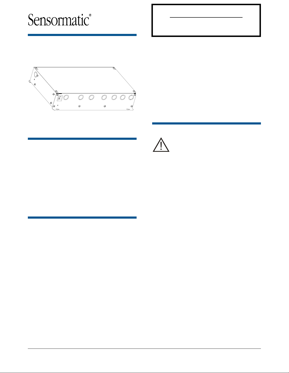
AMS-9060 Controller
Do Not Discard!
This document may be needed by code inspectors.
Leave it at the site until the installation is complete and
the system has been approved.
Installation Guide
ZE9060
ZE9060-2C
TYPE: AMS-9060
Contents
AMS-9060 Controller ............................................. 1
About this Guide .................................................... 1
To the Installer ....................................................... 1
About the Product .................................................. 2
Installation Requirements ...................................... 3
Controller Installation ............................................. 4
Specifications ...................................................... 12
Declarations ........................................................ 12
About this Guide
This installation and setup guide explains how to
install the AMS-9060 controller.
At least one but no more than four of the hybrid
series-parallel versions of the following antennas
can be connected to this controller:
Ultra•Exit (AMS-1090 Series / AMS-1100 Series)
Pro-Max 5
Options that connect to this controller are:
AMS-1060 digital remote alarm
Passive relays
Noise canceling antennas
Wired synchronization
CBC-4020-216 (UltraLink) or CBC-4055 (LDM II).
Preliminary
Other documents that may be required for
installation are:
AMS-9060 Planning Guide, 8200-1014-02
Pro-Max 5 Pedestals Installation Guide, 8200-1014-
07
Ultra•Exit Transceiver Antennas Installation Guide
(AMS-1090/AMS-1100 Series), 8200-0537-16
AMC-1060 Digital Remote Alarm Installation Guide,
8200-0505-01
CBC-4055 Local Device Manager II Installation
Guide, 8200-0858-01
Wired Sync Hookup Installation Guide, 8200-0537-
07.
To the Installer
Regulatory Restriction: In certain
countries, there may be installation
restrictions on the antennas. See antenna
installation guides for restrictions, if any.
Regulatory Restriction: Except for
power input connector all connections are
class 2.
Regulatory Restriction: For indoor use
only.
Intended Use: Only install this device as
described in this guide.
Declaration of Conformity: If this
product was installed in a European
Union or European Free Trade
Association member state, give the
Declaration of Conformity included with
this product to the manager or user. By
law, this information must be provided to
the user.
Because customer requirements dictate the
placement of system components, your
Sensormatic representative will supply this
information separately.
Because of the number of antennas and
accessories that can connect to this controller,
methodically install this system to avoid
problems. See “Connecting Pedestals” in this
guide for guidance on how to setup antennas.
© 2014 Sensormatic Electronics, LLC.
AMS-9060 CONTROLLER 8200-1014-01, REV. 1A
INSTALLATION GUIDE
1 of 13
Page 2

About the Product
The AMS-9060 controller is part of an EAS system
that:
Includes Ultra•Exit or Pro-Max 5 antennas used
to detect tags/labels at exits or in food store
checkout aisles.
Deters theft by activating an alarm when an
antenna detects the unique response of an
active Ultra•Max
label.
The AMS-9060 controller provides the following
installation features:
Antenna Support
The AMS-9060 controller supports up to two
(ZS9060-2) or four (ZS9060) transceiver exit
pedestals, or the same number of aisle pedestals,
each with separate transmit and receive coils.
Antennas can be set up as four transceivers, or
four transmit/receive pairs, or combinations of both
using a laptop computer and ADS 4 service
configurator software. Two receivers can be noise
canceling antenna coils. Automatic configuration is
available for the commonly used system
configurations.
Antenna coils can be set for phase flipping
(default), aiding, or figure-8 operation.
Note: Phase flipping is unavailable when noise
canceling antenna coils are used.
Alarm Support
The controller supports the following alarm
devices:
– Built-in alarm in the antenna (if used)
– Two externally-powered remote alarms such
as AMS-1060 digital remote alarms
– Up to two relays for devices such as security
cameras
– Externally-powered Sensormatic alarm
management or traffic flow device.
Auto Synchronization
Auto synchronization occurs during power up or
system reset. Auto sync can have different
outcomes depending on whether or not nearby
EAS transmitters are detected, they are properly
aligned to the ac-derived timing of the controller, or
too much ambient noise exists.
®
hard plastic tag or disposable
Preliminary
No transmitters detected. During initialization, the
controller determines if EAS transmitters are
nearby. If none are found, transmitter delay is set
to zero at initial power on, or set to the value stored
in the controller if not the initial power on.
Transmitters detected:
Transmitters detected and aligned. If
transmitters are correctly aligned, transmitter
delay is calculated and stored in the controller
for reference.
Transmitters detected and not aligned. If
transmitters are not aligned, transmitter delay is
set to zero at initial power on of the controller, or
set according to the value stored the controller if
not the initial power on.
Too much ambient noise. During initialization, the
controller locates other nearby EAS transmitters.
If ambient noise prevents the controller from
locating nearby EAS controllers and at initial
power on of the controller, transmitter delay is
set to zero.
If not initial power on of the controller, the zero
crossing delay stored in the controller is used.
Note: The controller stores the zero crossing delay
for when the controller could not determine a
reliable lock during subsequent power cycles.
Instead of using zero for the delay, the controller
uses the stored zero crossing delay.
Wired Synchronization
If a wired Tx sync device is connected to the
controller, the controller automatically uses its
signal as the timing reference instead of the ac
line. The service configurator indicates that wired
sync is active. See the Wired Sync Hookup
Installation Guide for wiring.
Controller Mounting
The controller has a built-in flange used to attach
the controller to a wall or ceiling using suitable
hardware.
Manual Voltage Selection
The voltage range (100-120 or 220-240 Vac) of the
controller must be manually selected at installation.
Conduit Support
Eleven knockouts receive exposed cables or
cables in conduit. Knockouts are available for
Class 2 wiring from antennas and low voltage
devices.
AMS-9060 CONTROLLER 8200-1014-01, REV. 1A
INSTALLATION GUIDE
2 of 13
Page 3
Installation Requirements
Verifying Equipment and Unpacking
Verify that all equipment has arrived. Ensure the
system configuration is correct for the site.
Unpack major components in a back room. At
the install site, lay out parts in the order used.
Do not clutter the aisle or cause a trip hazard.
Installer/Contractor
Have electrical work comply with the latest
national electrical code, national fire code, and
all applicable local codes and ordinances.
Coordinate work with other trades to avoid
interference.
Verify existing site conditions and coordinate
with the owner’s representative and appropriate
utilities as required.
Obtain copies of all related plans, specifications,
shop drawings and addenda to schedule and
coordinate related work.
Thoroughly review the project to ensure that all
work meets or exceeds the above requirements.
Bring alleged discrepancies to the attention of
Sensormatic Electronics.
Mounting Requirements
The controller has a built-in flange used to
attach the controller to a wall or ceiling using
suitable hardware. Structure and hardware must
support 12.08kg (26.06 lbs) or four times the
weight of the controller assembly.
Do not mount controller with its fan facing up.
AC Requirements
WARNING—RISK OF ELECTRIC
SHOCK! During installation, if the
antenna must be left unattended, turn off
power or cover high voltage components
to prevent unauthorized access to
hazardous voltages.
WARNING—RISK OF ELECTRIC
SHOCK! The ac power cord could be
carrying 120Vac or 240Vac.
Preliminary
WARNING! This device is not suitable
for an IT power distribution system
where impedance exists between neutral
and protective earth contacts.
CAUTION: When using a power cord,
install a socket-outlet near the controller
in an easily accessible location. The
appliance coupler or plug on the power
supply cord are the specified disconnect
devices.
CAUTION: DO NOT share the ac source
with neon signs, motors, computers,
cash registers, terminals, or data
communications equipment.
CAUTION: DO NOT use orange-colored
outlets dedicated for computer
equipment.
CAUTION: Select the appropriate power
cord based on the country of use.
Mounting the Controller
The controller can be mounted as follows:
On a shelf.
On a wall.
To a ceiling. Plywood with a surface larger than
the controller is secured to the ceiling studs that
hold the drywall. The controller then attaches
with suitable hardware to the plywood.
Equipment Required
Basic setup requires the following equipment:
AMS-9060 controller
Pedestal antennas
Hard tag (non-deactivatable Ultra•Max tag)
Ultra•Max low energy labels.
Advanced setup requires the following additional
equipment:
Laptop with Windows® 7, Windows® 95,
Windows® 98, Windows® NT, or Windows® 2000,
operating software
RS-232 Ultra•Max programming cable
ADS 4 service configurator software.
WARNING! Do not install this device
where highly combustible or explosive
products are stored or used.
WARNING! The ac source must be a 2-
wire type with ground. It also must be a
24-hour, unswitched outlet with less than
0.5Vac between neutral and ground.
AMS-9060 CONTROLLER 8200-1014-01, REV. 1A
INSTALLATION GUIDE
3 of 13
Page 4
Preliminary
Part
Qty.
Part number
Clamp, conduit
10
6010-0107-01
Label, Denan
0352-0398-07
Implanted Medical Devices
This anti-theft system complies with all applicable
safety standards. However, people with implanted
electronic medical devices may ask if the store has
an anti-theft system and its location. Although most
anti-theft systems are easily seen, some can be
concealed. To help these people, do the following:
Consider Health and Safety
Place the anti-theft system antennas so customers:
do not linger near or lean on them while making
their purchase
are only near the front of them while exiting the
checkout area.
For exit systems, place anti-theft system antennas:
Close to exit/entrance doors, encouraging the
customer to pass through them. DO NOT use
antennas intended for exits in an aisle
configuration.
Away from fixtures, equipment, amusements,
and other signage that can attract customers to
them.
Apply “Anti-Theft” Signage
“Anti-Theft” labels are placed on each antenna,
including those hidden behind door frames and
other structures. DO NOT cover these labels
with other signage.
In non-English speaking countries, apply “Anti-
Theft” labels in the local language to the
antennas. For hidden antennas, apply an “Anti-
Theft” label in the local language to each side of
the door frame facing the doorway about 1.2m
(4ft) above the floor. Order local language
labels (2412-0170-XX) from your distribution
center.
To improve customer awareness of the anti-
theft system, encourage the store to display
signs that state it has an anti-theft system.
Order awareness materials through your sales
representative.
Controller Installation
Tools required:
Tape measure
Pencil or marker
Electric drill
Phillips-head screwdriver or bit
Hand vacuum or broom
Parts required:
Install Kit 0352-0286-02
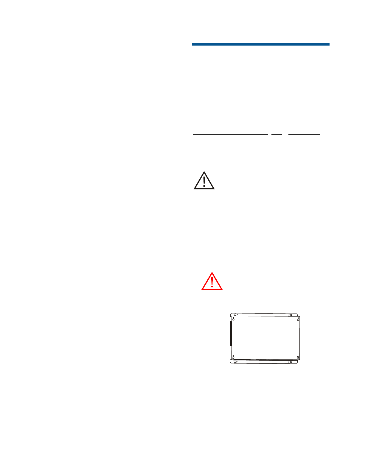
Mounting the Controller
CAUTION: Keep 22.9cm (9in) of free
space to the right of the controller for
screwdriver access (to facilitate
detachment of controller electronics).
1. Detach the top cover from the controller.
2. Remove knockouts closest to the connectors to
be used, then reattach the side plate.
3. Set the controller on a shelf, or using suitable
anchors and hardware, mount it to a wall or to a
ceiling. Note: Ceiling attachment requires
plywood be first attached to the ceiling and then
the controller attached to the plywood.
WARNING! Both the anchor system
and the wall or ceiling must be able to
support 12.08kg (26.6 lbs) or four
times the weight of the controller
assembly.
AMS-9060 CONTROLLER 8200-1014-01, REV. 1A
INSTALLATION GUIDE
4 of 13
4. Run cables from antennas and devices through
the appropriate knockouts and secure them
using the cable clamps provided. See Figure 1
for the locations of the connectors.
Page 5

Preliminary
120 Vac:
J1 shunt IN
240 Vac:
J1 shunt OUT
USA-IEC 320, 18/3, 125V, 10A, 7.5ft.
0351-0547-01
Schuko-IEC 320, 1mm sq., 250V, 10A, 2.5m
0351-0547-02
UK-IEC 320, 1mm sq., 250V, 10A, 2.5m
0351-0547-03
Japan-IEC 320, 2mm sq., 250V, 15A, 2.5m
0351-0547-04
US-Filter, Line, 125V, 6A, Plug-in
0351-0547-05
Australia to IEC 320, 2.5m, 250V, 10A
0351-0547-07
AC IN
(120Vac/
240Vac)
Ferrite
Cut wires here
Connecting AC Power
The controller can receive AC power either through
a power cord or through a hardwired connection.
CAUTION: A 10A, 2-pole, ganged
disconnect device, which also provides
short circuit and overload protection, and
has a minimum 3mm open circuit
clearance, in accordance with the
National Electric Code and applicable
local codes must be installed by a
licensed electrician at a location readily
accessible to the equipment.
1. Locate the voltage shunt, which is in a bag
taped inside the enclosure.
WARNING: RISK OF ELECTRIC
SHOCK! Ensure that the system is
not powered before moving the
shunts.
2. Select the proper voltage for the site using the
shunt (2109-0062-01) included with the kit. The
default setting is 240Vac.
WARNING—RISK OF ELECTRIC
SHOCK! The ac power cord may carry
120Vac or 240Vac.
CAUTION: When using a power cord,
a socket-outlet must be installed near
the controller and in an easily
accessible location.
2. Plug the power cord into the IEC320 receptacle
and the power source.
Hardwired connection
CAUTION: Use only copper wire.
WARNING—RISK OF ELECTRIC
SHOCK! The ac power cord may carry
120Vac or 240Vac. Ensure the power
is turned off at the circuit breaker
before performing the following
procedure.
Power cord connection
1. Choose a power cord for the country of use.
1. Ensure the controller does is not powered and
the hard-wire cables are not powered.
2. Unplug the existing power cable connector
from the main board, loosen the screws
holding the two wires, and pull out the wires.
3. Unscrew the ground lug from the main board.
Save the ground screw.
4. Cut the three wires connecting the IEC320
connector to the wiring harness with the ferrite.
They should be cut as close as possible to the
IEC320 connector.
5. Cut the ferrite from the power cord.
AMS-9060 CONTROLLER 8200-1014-01, REV. 1A
INSTALLATION GUIDE
5 of 13
Page 6

Preliminary
Ground screw
Washer (slot
points down
towards wire
jacket)
Ground wire
Cable
jacket
6. Remove one of the knockouts accessing the
ac connection area. Thread a cable clamp into
the hole.
7. Route the ac cable through a cable clamp,
leaving about 15.2cm (6in) out the other side.
Tighten the clamp around the cable.
8. Put the ferrite on the Line (L1), Neutral (L2)
and ground wires. Ensure the wires wrap
around the ferrite and pass through again like
they did on the existing wiring harness.
9. Expose about 5cm (2in) of insulated wires:
Line (L1), Neutral (L2), and ground.
10. Connect the AC power wires to the power
connector P1 on the main board in the
pedestal.
The power connector accepts 0.75 to 2.0 mm
(18 to 14 AWG) wire. Connect the Line wire
(black) to pin 1, the Neutral wire (white) to pin
2, and the ground wire (green) to the screw on
the main board, as shown below.
If you remove the connector, do not pull it out
by the wires; pull on the connector.
When connecting the ground wire, ensure the
slot on the washer is pointing down to allow the
jacket on the cable to fit behind the washer.
Connecting Pedestals
Transceiver pedestals connect to the AMS-9060
controller with two cables: Transceiver (Tx/RX)
cables and Alarm/Communication cables. They
connect to the controller at the following
connectors:
Transceiver connectors (P19, P21, P23,
P25). These four connectors labeled PED A, B,
C, and D, support Tx/Rx antennas designated
A, B, C, and D. Table 1 shows connections for
various antenna configurations. If “auto
configuration” is enabled, the system
automatically attempts to configure itself based
on the number of antennas detected. Only the
most commonly used configurations are auto
configured.
2
Alarm/Communication connectors (P20,
P22, P24, P26): Four connectors support the
antennas audio/visual alarms, transmitter/
alarms inhibit function, and peripheral RS-485
network communication. Note:
Transmitter/Alarms inhibit function and
peripheral RS-485 network communications
are only available in Ultra•Exit alarm antennas
and Pro-Max 5 pedestals.
WARNING—RISK OF ELECTRIC
SHOCK! The ac power cord may carry
120Vac or 240Vac.
CAUTION: After you connect the
ground wire, ensure all of the strands
of the ground wire are beneath the
washer. Loose strands can cause a
short circuit.
1. Ensure controller power is off.
2. Connect antenna cables to the controller
according to how the antennas are intended to
perform. Refer to diagrams and tables on pages
8 and 9 of this guide. See examples of pedestal
installations in the antenna installation guide.
AMS-9060 CONTROLLER 8200-1014-01, REV. 1A
INSTALLATION GUIDE
6 of 13
Page 7

Preliminary
Connecting Receivers
Auxiliary receivers connect to the AMS-9060
controller at the following connectors, with top coils
connecting to the Coil 1 connections and bottom
coils using the Coil 2 connections:
Receiver 1 (P3)
Receiver 2 (P4)
Receiver 3 (P5)
Receiver 4 (P17)
Antennas/coils connected to receiver inputs are
designated A, B, C, and D. These connectors
default to receive function with no auto detection.
ABOUT NOISE CANCELING COILS:
Noise canceling coils, such as a Ranger antenna
or the top coil of a pedestal antenna, are used to
cancel noise that interferes with detector operation.
Noise canceling coils only connect to the top
coil (Coil 1) input on connectors P5 and P17.
To accept a noise canceling coil, the auxiliary
input must be in noise canceling mode (set
using service configurator software). Save
adjustments to default settings if they are to be
used on the next power cycle or system reset.
Move the noise canceling coil around while
monitoring power levels on a laptop computer to
find where noise cancellation is best. This is
where the coil should be installed.
The location for the noise canceling coil must be
practical as well as yield satisfactory results.
If connecting a noise canceling coil and a
receive antenna into the same connector, the
top and bottom coils of the receive antenna
must share the Coil 2 connection (done in the
field by the technician switching the antenna
wire connections). Thus phase flipping is
unavailable when noise canceling coils are
used.
AMS-9060 CONTROLLER 8200-1014-01, REV. 1A
INSTALLATION GUIDE
7 of 13
Page 8

Figure 1. AMS-9060 connectors (with pinouts), jumpers, and switches
P3 P4 P5 P17 J2 P18 J3
P32
P30
P31
P28
P26
P25
P24
P23
P22
P21
P20
P19
P1
1 2
J1
S1
S2
S3
1 1 88
Off
On
Off
On
1 2 3 4 5 1 2 34 5 1 2 34 5 1 2 3 4 5 1 2 34 5
1 2 31 2 31 2 3
1 2 3
4 5
1 2 3 4 5 1 2 3 4 5 1 2 3 4 5 1 2 3 45
BKRD O GNWT BKRD O GNWT
BKRD O GNWT
BKRD O GNWT
P32 (NET RS485)
Pin 3 – (Shield)
Pin 2 – (Network RS485 HI)
Pin 1 – (Network RS485 LO)
P18 (WIRED SYNC)
Pin 1 – Black (Tx Burst High)
Pin 2 – Red (Tx Burst Low)
Pin 3 – Green (Arm High)
Pin 4 – White (Arm Low)
Pin 5 – (Shield)
P30, P31 (REM ALARM 1 and 2)
Pin 3 – (Shield)
Pin 2 – (Peripheral RS485 HI)
Pin 1 – (Peripheral RS485 LO)
J2 (RELAY A-B)
Pin 8 – NC 1
Pin 7 – Common 1
Pin 6 – NO 1
Pin 5 – NC 2
Pin 4 – Common 2
Pin 3 – NO 2
Pin 2 – Ground
P3, P4, P5, P17 (RX1-4)
Pin 1 – Black (Antenna [A-D]1)
Pin 2 – Red (Antenna [A-D]1 return)
Pin 3 – Green (Antenna [A-D]2)
Pin 4 – Gray/White (Antenna [A-D]2 return)
Pin 5 – Violet / ‘X’ (Shield)
Note: Color may vary depending on device.
P19, P21, P23, P25 (PED A-D Tx/Rx)
Pin 1 – Black (Bottom coil return)
Pin 2 – Red (Bottom coil)
Pin 3 – (Shield)
Pin 4 – Green (Top coil return)
Pin 5 – White (Top coil)
P20, P22, P24, P26 (COMM A-D)
Pro•Max 5
Pin 1 – (Shield)
Pin 2 – Black (Ground)
Pin 3 – Orange (12V)
Pin 4 – Brown (Peripheral RS485 LO)
Pin 5 – Red (Peripheral RS485 HI)
Ultra•Exit (AMS-9060 compatible)
Pin 1 – (Shield)
Pin 2 – No connect (Ground)
Pin 3 – Brown (12V)
Pin 4 – Black (Peripheral RS485 LO)
Pin 5 – Red (Peripheral RS485 HI)
P28 (EXT. TX INHIBIT)
Pin 1 – (Tx Inhibit 1)
Pin 2 – (Ground)
Pin 3 – (Tx Inhibit 2)
Pin 4 – (Ground)
Pin 5 – (Tx Inhibit 3)
P1 (AC)
Pin 1 – L1/PRI
Pin 2 – L2/NEU
J3 (RS232)
Pin 1 – (RxD)
Pin 2 – (TxD)
Pin 3 – (Ground)
Pin 4 – (No Connect)
S1
A/B DIP Switches
Pins 1-4 – Ped A
Pins 5-8 – Ped B
On – Port is Tx/Rx
Off – Port is Tx only,
Rx is at Rx
port
S3 (Flash Override Pushbutton)
DS1
(Power LED)
F1 (Fuse L1 )
F2 (Fuse L2 )
J1 (120V/240V)
120V - In
240V - Out
S2
C/D DIP Switches
Pins 1-4 – Ped C
Pins 5-8 – Ped D
On – Port is Tx/Rx
Off – Port is Tx only,
Rx is at Rx
port
Reserved
(P2)
Reserved
(P16)
Grounding Screw
Preliminary
AMS-9060 CONTROLLER 8200-1014-01, REV. 1A
INSTALLATION GUIDE
8 of 13
Page 9

Preliminary
EXIT SYSTEM
Exit 1
Exit 2
Auto
Config.*
MODE
PED 1 Connections
PED 2 Connections
PED 3 Connections
PED 4 Connections
None
Disabled
Disabled
Disabled
Disabled
Disabled
Disabled
Disabled
Disabled
NO
Single Transceiver
RX A / Alrm A
TX A
NA
NA
NA
NA
NA
NA
YES
1-2 Dual
RX A / Alrm A
TX A
RX C / Alrm C
TX C
NA
NA
NA
NA
YES
1-2 Dual
Sim.-Alternating
RX A / Alrm A
TX A
RX C / Alrm C
TX C
NA
NA
NA
NA
NO
1-2-3 Split
RX A / Alrm A
TX A
RX C / Alrm C
TX C
RX B / Alrm B
TX B
NA
NA
YES
1-2-3-4 Quad
RX A / Alrm A
TX A
RX C / Alrm C
TX C
RX B / Alrm B
TX B
RX D / Alrm D
TX D
YES
1-2 Dual with Ferrites
RX A / Alrm A
TX A
RX C / Alrm C
TX C
RX B
N/A
RX D
NA
NO
1-2 Transceiver-
Ferrite
RX A / Alrm A
TX A
RX C / Alrm C
TX C
RX B
N/A
RX D
NA
NO
1-2 Backfield
RX A / Alrm A
TX A
RX C / Alrm C
TX C
NA
NA
NA
NA
NO
1-2 Alternating
RX A / Alrm A
TX A
RX C / Alrm C
TX C
NA
NA
NA
NA
NO
1-2-3 Ferrites-
Transceiver-Ferrites
RX A
N/A
RX C / Alrm C
TX C
RX B
N/A
NA
NA
NO
1-2 Dual 3 Single
RX A / Alrm A
TX A
RX C / Alrm C
TX C
RX B / Alrm B
TX B
NA
NA
NO
1-2 Bfield 3 Single
RX A / Alrm A
TX A
RX C / Alrm C
TX C
RX B / Alrm B
TX B
NA
NA
NO
1-2_3-4 Dual
RX A / Alrm A
TX A
RX C / Alrm C
TX C
RX B / Alrm B
TX B
RX D / Alrm D
TX D
NO
1-2_3-4 Alternating
RX A / Alrm A
TX A
RX C / Alrm C
TX C
RX B / Alrm B
TX B
RX D / Alrm D
TX D
NO
1-2-3-4 Alternating
RX A / Alrm A
TX A
RX C / Alrm C
TX C
RX B / Alrm B
TX B
RX D / Alrm D
TX D
NO
1-2-3 Split Alternating
RX A / Alrm A
TX A
RX C / Alrm C
TX C
RX B / Alrm B
TX B
NA
NA
NO
1-2_3-4 Backfield
RX A / Alrm A
TX A
RX C / Alrm C
TX C
RX B / Alrm B
TX B
RX D / Alrm D
TX D
NO
1_2_3_4 Single
Transceiver**
RX A / Alrm A
TX A
RX C / Alrm C
TX C
RX B / Alrm B
TX B
RX D / Alrm D
TX D
NO
1-2 Dual 3-4 Bfield
RX A / Alrm A
TX A
RX C / Alrm C
TX C
RX B / Alrm B
TX B
RX D / Alrm D
TX D
NO
Table 1. Exit System
Note: Numbers 1, 2, 3, and 4 under mode column indicate the pedestals used. 1-2_3-4 indicates that 1 and 2
pedestals are in one exit, and 3 and 4 pedestals are in another. 1-2-3-4 indicates all pedestals are in one exit.
Note: Disregard receiver settings when using antennas as transceivers.
* Only applies to Ultra•Exit antennas.
** In 1_2_ 3_ 4 Single Transceiver Mode (where each antenna protects an exit), each antenna alarms independently.
AMS-9060 CONTROLLER 8200-1014-01, REV. 1A
INSTALLATION GUIDE
9 of 13
Page 10

Preliminary
Antenna
Controller
Input
DIP S1
DIP S2
Ultra•Exit or
Pro-Max 5
Transceiver
TXA
1–4 On,
rest don’t care
Don’t Care
TXB
5–8 On,
rest don’t care
Don’t Care
TXC
Don’t Care
1–4 On,
rest don’t care
TXD
Don’t Care
5–8 On,
rest don’t care
Rx Only
RXA
1–4 Off,
rest don’t care
Don’t Care
RXB
5–8 Off,
rest don’t care
Don’t Care
RXC
Don’t Care
1–4 Off,
rest don’t care
RXD
Don’t Care
5–8 Off,
rest don’t care
Noise Coil 1
RXC
(top coil)
Don’t Care
1–2 Off,
rest don’t care
Noise Coil 2
RXD
(top coil)
Don’t Care
5–6 Off,
rest don’t care
Setting Dip Switches
IMPORTANT! DIP S1 and DIP S2 are located on
the circuit board of the controller. When connecting
antennas, set switches 1–8 of each DIP according
to the number and type of antennas used.
For example, if using a:
1-2 dual pedestal exit system using two
Ultra•Exit alarm antennas as transceivers:
– Set S1 switches 1–4 and S2 switches 1–4 to
“on” (switches 5–8 of S1 and S2 can be left
either on or off).
– Also ensure no receive antennas such as
noise coils are connected to the controller
when using transceivers.
Connecting Optional Devices
Connect any optional devices to their connectors.
Relay connectors (J2): The controller has two
double-pole, double-throw (DPDT) relays, each
configurable using service configurator software.
Each relay:
Triggers devices such as externally powered
remote alarms, time-lapse VCRs, and security
cameras; one device per detection zone.
Accepts three wires and a shield. Cable shields
share one pin on the connector.
Remote alarm connector (P30, P31): These
connectors can control two externally-powered
digital remote alarms, such as an AMC-1060.
RS-485 network connector (P32): This connector
supports RS-485 communication for remote
diagnostics. It is also the connector for connecting
to UltraLink devices.
Wired Tx sync connector (P17): This connector
is used to connect an AMS-9060 controller to an
AMS-9060, AMS-9050, or AMS-9040 controller to
synchronize them to avoid cross interference.
RS-232 service connection (J3): Located on the
main board, the RJ-22 connector receives the
cable from a laptop computer that is used to locally
setup and diagnose the detection system.
1-2_3-4 dual pedestal exit system or 1-2-3-4
quad system using four Ultra•Exit alarm
antennas as transceivers:
– Set all S1 and S2 switches to “on”.
– Also ensure no receive antennas such as
noise coils are connected to the controller
when using transceivers.
Noise coils: If using noise coils, turn off S1
switches 1–2 for RxC and/or S2 switches 5–6
for RxD.
AMS-9060 CONTROLLER 8200-1014-01, REV. 1A
INSTALLATION GUIDE
10 of 13
Page 11

Preliminary
DB-9
RJ-11/12
RJ-10/22 to
controller
Configuring the System
The AMS-9060 controller enables you to change
controller parameters using your laptop computer
and the ADS 4 service configurator.
1. Turn on the service laptop and launch the ADS
4 service configurator.
Note: For how to use configurator settings, click
Help on the configurator.
IMPORTANT! Ensure the controller power is off.
Never restart or boot up a computer connected
to an active controller. Doing so disables the
mouse function on the computer.
2. Connect the DB-9-to-RJ-11/12 connector to
the DB-9 serial port on your laptop computer.
Only pins 2, 3, and 5 are used.
Verifying Operation
1. Pass an active security tag by each antenna to
verify antenna performance. Refer to Help if
monitoring or adjustments are necessary.
2. Check that the antenna alarm lamp lights when
a tag/label is passed through the checkout
aisle, or if the system is covering adjacent
aisles, that the lamp lights only in the aisle the
tag/label was in.
3. If the pick rate is acceptable, installation is
complete. Reattach the top cover.
4. If you are installing this controller in Japan and
the Japanese regulatory label (0352-0398-07)
has not been affixed, attach it to a flat surface
on the controller.
RS-232 port on
3. Connect the RJ-11/12 connector of the service
cable to the DB-9 connector and the RJ-10/22
connector on its other end to the RS-232 port
(J3) on the controller.
4. Turn on the controller.
5. Using the “Setup” page on the configurator:
Check that antenna selections match
antennas physically installed. If not, check
antenna connections to the controller.
Setup parameters for lamps, audio, relays,
and remote alarms.
6. Using the “Tx Configuration” page, set Tx
current for each antenna and enable/disable
transmitters, if necessary.
AMS-9060 CONTROLLER 8200-1014-01, REV. 1A
INSTALLATION GUIDE
11 of 13
Page 12

Preliminary
Specifications
Electrical
Power Supply
Primary input ........................................... 100-120Vac or
220-240Vac @ 50–60Hz
Primary power fuse ...................... 3.15A, 250V, slo-blow,
hi-breaking
Current draw (120V) ........................................ <2.1Arms
Current draw (240V) ........................................ <0.9Arms
Input power (120V) .............................................. <165W
Input power (240V) .............................................. <165W
Transmitter
Operating frequency .............................. 58kHz (±200Hz)
.......................................................... (sync pulse) 56kHz
Transmit burst duration .......................................... 1.6ms
Transmit current maximum (2.4m pedestals) ... 20A peak
Transmit current maximum (2.0m pedestals) ... 16A peak
Burst Repetition Rate:
Based on 50Hz ac ............................. 75Hz or 37.5Hz
Based on 60Hz ac ................................ 90Hz or 45Hz
Receiver
Center frequency ................................................... 58kHz
Environmental
Ambient temperature .................................... 0°C to 50°C
(32°F to 122°F)
Relative humidity ............................................... 0 to 90%
non-condensing
Enclosure Rating ..................................................... IPX0
Evaluated for altitudes less than 3000m (9800ft)
Mechanical
Height ....................................................... 8.87cm (3.5in)
Width .................................................. 29.82cm (11.74in)
Length ................................................. 46.10cm (18.15in)
Weight .................................................. 3.02kg (6.65 lbs)
Declarations
TYPE: AMS-9060
Model: AMS-9060 (4 channel controller)
Model: AMS-9060-2C (2 channel controller)
Regulatory Compliance
EMC ................................................ 47 CFR, Part 15
EN 61000-3-2
EN 61000-3-3
EN 300 330-2
EN 301 489-3
EN 301 489-1
EN 55022
EN 55024
ICES-003
RSS-210
Safety (second edition) ................... UL 60950-1
CSA C22.2.60950-1
EN 60950-1
FCC ID: BVCAMS90604 (4 channel controller)
FCC ID: BVCAMS90602 (2 channel controller)
This device complies with part 15 of the FCC Rules. Operation
is subject to the following two conditions: (1) This device may
not cause harmful interference, and (2) this device must accept
any interference received, including interference that may cause
undesired operation.
NOTE: This equipment has been tested and found to comply
with the limits for a Class A digital device, pursuant to part 15 of
the FCC Rules. These limits are designed to provide reasonable
protection against harmful interference when the equipment is
operated in a commercial environment. This equipment
generates, uses, and can radiate radio frequency energy and, if
not installed and used in accordance with the instruction
manual, may cause harmful interference to radio
communications. Operation of this equipment in a residential
area is likely to cause harmful interference in which case the
user will be required to correct the interference at his own
expense.
IC: 3506A-AMS90604 (4 channel controller)
IC: 3506A-AMS90602 (2 channel controller)
This device complies with Industry Canada licence-exempt RSS
standard(s). Operation is subject to the following two conditions:
(1) this device may not cause interference, and (2) this device
must accept any interference, including interference that may
cause undesired operation of the device.
Le présent appareil est conforme aux CNR d’Industrie Canada
applicables aux appareils radio exempts de licence.
L’exploitation est autorisée aux deux conditions suivantes : (1)
l’appareil ne doit pas produire de brouillage, et (2) l’utilisateur de
l’appareil doit accepter tout brouillage radioélectrique subi,
même si le brouillage est susceptible d’en compromettre le
fonctionnement.
This Class A digital apparatus complies with Canadian ICES-
003.
Cet appareil numérique de la classe A est conforme à la norme
NMB-003 du Canada.
AMS-9060 CONTROLLER 8200-1014-01, REV. 1A
INSTALLATION GUIDE
12 of 13
Page 13

EQUIPMENT MODIFICATION CAUTION: Equipment changes
or modifications not expressly approved by Sensormatic
Electronics, LLC, the party responsible for FCC compliance,
could void the user's authority to operate the equipment and
could create a hazardous condition.
See “About the Product” on page 2.
Other Declarations
WARRANTY DISCLAIMER: Sensormatic Electronics, LLC
makes no representation or warranty with respect to the
contents hereof and specifically disclaims any implied
warranties of merchantability or fitness for any particular
purpose. Further, Sensormatic Electronics, LLC reserves the
right to revise this publication and make changes from time to
time in the content hereof without obligation of Sensormatic
Electronics, LLC to notify any person of such revision or
changes.
LIMITED RIGHTS NOTICE: For units of the Department of
Defense, all documentation and manuals were developed at
private expense and no part of it was developed using
Government Funds. The restrictions governing the use and
disclosure of technical data marked with this legend are set
forth in the definition of “limited rights” in paragraph (a) (15) of
the clause of DFARS 252.227.7013. Unpublished - rights
reserved under the Copyright Laws of the United States.
TRADEMARK NOTICE: Sensormatic is a registered trademark
of Sensormatic Electronics, LLC. Other product names
mentioned herein may be trademarks or registered trademarks
of Sensormatic or other companies.
No part of this guide may be reproduced in any form without
written permission from Sensormatic Electronics, LLC.
Preliminary
AMS-9060 CONTROLLER 8200-1014-01, REV. 1A
INSTALLATION GUIDE
13 of 13
 Loading...