

Tyco Safety Sensormatic AMS1080 Users manual
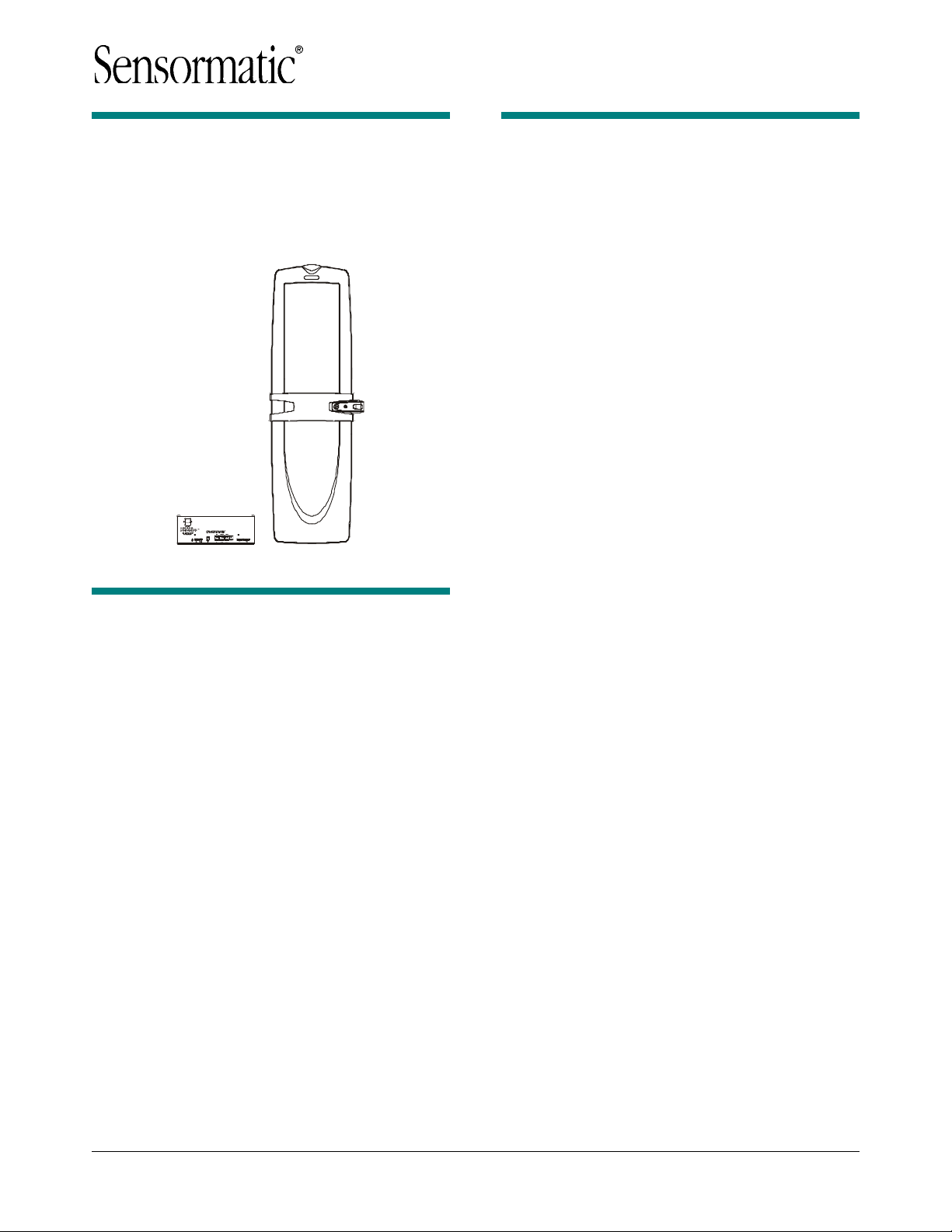
AMS-1080
Detection System
Installation and Service Guide
Contents
To the Installer....................................................... 1
About the Product.................................................. 2
Device Connections .............................................. 4
Installation Features.............................................. 6
Service Features ................................................... 7
Installation Requirements...................................... 8
AMS-1080 Antenna Installation............................. 9
Against a Wall or Counter .................................. 9
To a Railing Post.............................................. 10
Controller Installation........................................... 12
AC Hookup .......................................................... 12
System Setup ...................................................... 13
Antenna Connections....................................... 13
Software Selections ......................................... 14
Verifying Operation.............................................. 14
Troubleshooting................................................... 15
Fuse Replacement .............................................. 17
Specifications ...................................................... 17
Declarations ........................................................ 18
To the Installer
This installation and service guide explains how to
install, setup, and service the AMS-1080 detection
system.
Parts required to install this system are:
- AMS-1080 Controller
- AMS-1080 Controller Mounting Kit
0352-0203-01 (optional)
- AMS-1080 Antenna(s)
- AMS-1080 Antenna Counter Mounting Kit(s)
0352-0199-01 or Pole Mounting Kit(s)
0352-0198-01
- ZKRANGER-DG Ranger antenna kits, as
required (purchase separately).
Other documents that may be required for
installation are:
- AMS-1080 Planning Guide, 8200-0418-02
- ZKRANGER-DG Ranger Installation Guide,
8200-0452-01
- AMS-1080 Theory or Operation, 8200-0418-03.
Note:
- Because customer requirements dictate the
placement of system components, your
Sensormatic representative will supply this
information separately.
- If this product was installed in a European
Union or European Free Trade Association
member state, please give the Declaration of
Conformity included with this product to the
manager or user. By law, this information must
be provided to the user.
- The controller is cooled by a fan that is factory
set to 240Vac. If using 120Vac, remove the
cover from the controller and change fan
jumpers to 120Vac. See label inside the
controller for jumper locations.
- Install the AMS-1080 antenna at least 5cm (2in)
from metal surfaces.
© 2004 Sensormatic
AMS-1080 DETECTION SYSTEM 8200-0418-01, REV. A
INSTALLATION AND SERVICE GUIDE
1 of 18
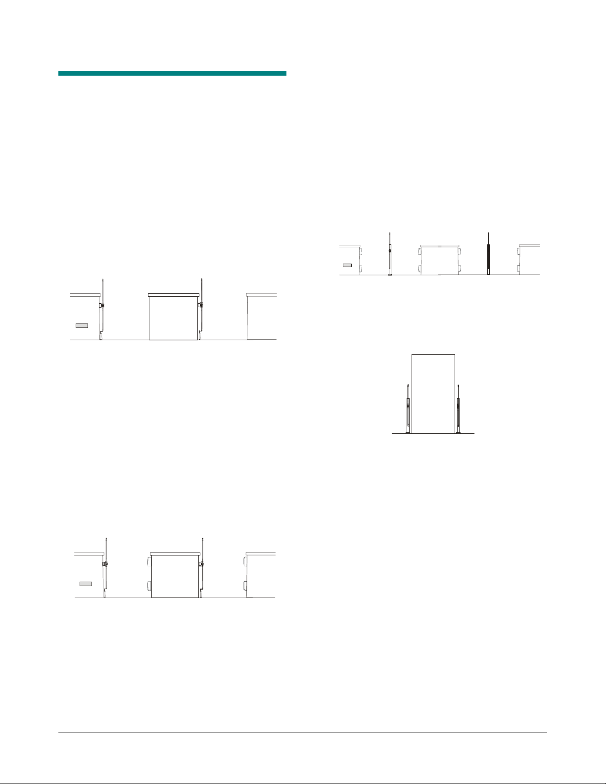
About the Product
The AMS-1080 detection system detects EAS
tags/labels in food store checkout aisles, with each
aisle independently supported. The detector
consists of a controller and one of the following
antenna combinations:
- Up to two individual aisles supported with
transceivers.
For this setup, an AMS-1080 antenna is set up
as a transceiver in each aisle. The antenna
furthest from the controller requires a trench to
route its cables to the controller.
The AMS-1080 antennas in each aisle can be
set to alarm independently.
A
B
- Up to two individual pairs of adjacent aisles
(A1/A2 and B1/B2) supported.
For each adjacent aisle, an AMS-1080 antenna
is set up as a transmitter on a railing post
between the two aisles and a pair of Ranger
receive antennas (purchased separately) are
setup opposite the each side of the antenna.
The alarm lamp in the AMS-1080 antenna
automatically signals which aisle a security
tag/label was detected.
Antennas furthest from the controller require a
trench to route their cables to the controller.
A1 A2 B1 B2
- Two AMS-1080 antennas set up at a doorway
either in alternating transmit-receive or dual
transceiver configurations. Alarms in both
antennas activate simultaneously.
- Up to two individual aisles (A and B) supported
with improved detection or with backfield
reduction.
For improved detection, an AMS-1080 antenna
is set up as a transceiver in each aisle and a
pair of Ranger receive antennas (purchased
separately) are set up opposite the antenna.
For backfield reduction, the AMS-1080 antenna
is set up as a transmitter instead.
The AMS-1080 antennas in each aisle can be
set to alarm independently.
Antennas furthest from the controller require a
trench to route their cables to the controller.
A
B
AMS-1080 DETECTION SYSTEM 8200-0418-01, REV. A
INSTALLATION AND SERVICE GUIDE
2 of 18

Basic Operation
The AMS-1080 detector deters theft by activating
an alarm when it detects the unique response of an
active Ultra•Max hard plastic tag or disposable
label.
To detect a tag/label, AMS-1080 antenna(s)
connected to the controller emit a magnetic field
close to the tag/label’s natural frequency causing it
to vibrate or “ring” at the frequency of the field.
When the field is removed, energy in the tag/label
dissipates causing an exponential ring down.
The AMS-1080 antenna(s)—and ferrite (Ranger)
antennas, if used—pick up incoming signals and
send them to the controller which processes them
to determine if they are indicative of ring down. If
they are, then the controller activates an
audio/visual alarm indicator at the top of the AMS1080 antenna that detected the tag/label.
When the AMS-1080 antenna is positioned
between two adjacent checkout lanes, the visual
alarm indicator can be set to indicate the aisle
where the active tag was detected.
AMS-1080 Antenna Features
The AMS-1080 antenna features the following:
- Emits the detection field and receives the
tag/label signal
- Figure “O” and Figure “8” transmit coils in the
antenna combine to produce a field that
alternates between the top and bottom of the
antenna. These coils can also be set for
maximum field in the top of the antenna only or
the bottom of the antenna only. Maximum
operating current is 15A
- Mounts to the side of a wall or counter, or to a
railing post using hardware supplied
- Has an alarm lamp for each side of the antenna
- Has a “transmitter on” lamp that lights when the
transmitter is on
- Has two hardwired cables that connect to the
controller. Cable length is 7.6m (25ft). DO NOT
CUT! Shorter cables can reduce operating
performance.
Ranger Antenna Features
AMS-1080 Controller Features
The AMS-1080 controller features the following:
- Independent Tx and Rx connections that
support two transmitters and four receivers
- Supports up to two noise canceling coils
- Controls pedestal alarms
- Has “ac line synchronization” and “tag too close”
functions.
- Supports wired transmitter synchronization
- Is adjusted either on-site or remotely using a
laptop computer and AMS-1080 service
configurator software
- Built-in mounting flange enables it to mount
vertically to a wall or inside the checkout
counter. The controller can also rest on a shelf.
- Only receives the tag/label signal
- Mounts to a wall or counter opposite the AMS1080 antenna
- These ferrite antennas connect together as a
pair and have a hardwired cable that connects
to a “Auxiliary Receive” connector on the
controller.
AMS-1080 DETECTION SYSTEM 8200-0418-01, REV. A
INSTALLATION AND SERVICE GUIDE
3 of 18
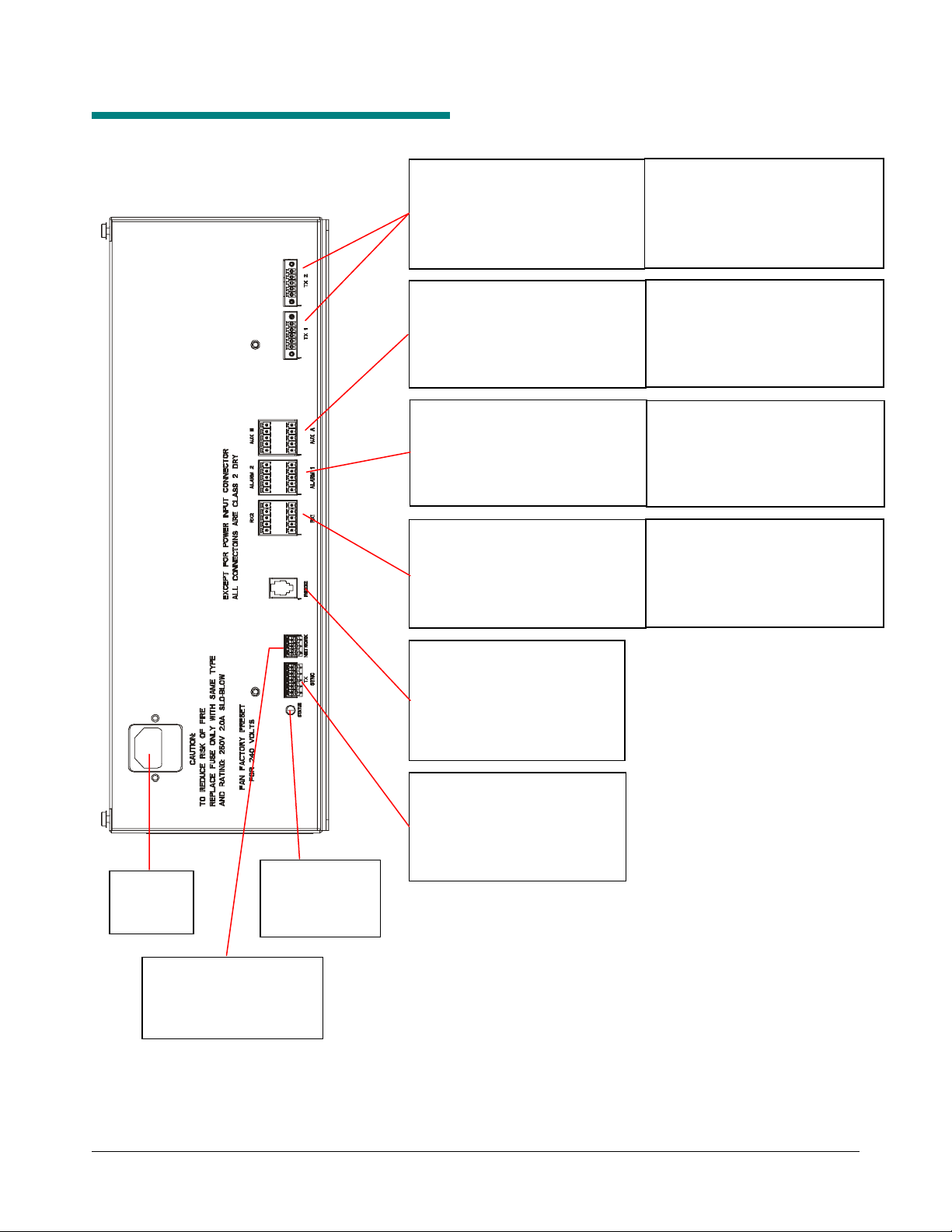
Device Connections
Tx 1 TRANSMIT ANTENNA (P58)
Pin 1 - Black (Figure-8 return)
Pin 2 - Red (Antenna A2)
Pin 3 - White with an 'X' (Shield)
Pin 4 - Green (Aiding return)
Pin 5 - White (Antenna A1)
AUX. RECEIVE (P56A)
Pin 1 - Black (Ant C1, noise can.)
Pin 2 - Red (Ant C1 return)
Pin 3 - Green (Ant C2)
Pin 4 - White (Ant C2 return)
Pin 5 - 'X' (Shield)
PEDESTAL ALARM 1 (P55A)
Pin 1 - White with an 'X' (Shield)
Pin 2 - Yellow (Audio 1)
Pin 3 - Orange (Alarm 1B)
Pin 4 - Blue (Alarm 1A)
Pin 5 - Brown (12V)
Rx 1 RECEIVE ANTENNA (P53A)
Pin 1 - Black (Ant A1)
Pin 2 - Red (Ant A1 return)
Pin 3 - Green (Ant A2)
Pin 4 - Gray or White (Ant A2 return)
Pin 5 - Violet / 'X' (Shield)
Tx 2 TRANSMIT ANTENNA (P59)
Pin 1 - Black (Figure-8 return)
Pin 2 - Red (Antenna B2)
Pin 3 - White with an 'X' (Shield)
Pin 4 - Green (Aiding return)
Pin 5 - White (Antenna B1)
AUX. RECEIVE (P56B)
Pin 1 - Black (Ant D1, noise can.)
Pin 2 - Red (Ant D1 return)
Pin 3 - Green (Ant D2)
Pin 4 - White (Ant D2 return)
Pin 5 - 'X' (Shield)
PEDESTAL ALARM 2 (P55B)
Pin 1 - White with an 'X' (Shield)
Pin 2 - Yellow (Audio 2)
Pin 3 - Orange (Alarm 2B)
Pin 4 - Blue (Alarm 2A)
Pin 5 - Brown (12V)
Rx 2 RECEIVE ANTENNA (P53B)
Pin 1 - Black (Ant B1)
Pin 2 - Red (Ant B1 return)
Pin 3 - Green (Ant B2)
Pin 4 - Gray or White (Ant B2 return)
Pin 5 - Violet / 'X' (Shield)
AC IN
(120Vac/
240Vac)
RS-485 NETWORK (P8)
Pin 1 - Black
Pin 2 - Red
Pin 3 - X (Shield)
LED
System Status
Indicator
RS-232 SERVICE (RJ-22)
Pin 1 - Rx
Pin 2 - Tx
Pin 3 - Ground
Pin 4 - Ground
WIRED Tx SYNC (P2)
Pin 1 - Black (Tx Burst High)
Pin 2 - Red (Tx Burst Low)
Pin 3 - Green (Arm High)
Pin 4 - White (Arm Low)
Pin 5 - 'X' (Shield)
AMS-1080 DETECTION SYSTEM 8200-0418-01, REV. A
INSTALLATION AND SERVICE GUIDE
4 of 18

Transmit Antenna (Tx1, Tx2)
These two connectors each receive a transmit
cable from an AMS-1080 antenna.
Receive Antenna
(Rx1, Rx2, Aux A, Aux B)
Connectors Rx1 and Rx2 each receive a receive
cable from an AMS-1080 antenna or from a ferrite
(Ranger) antenna. Connectors Aux A and Aux B
each receive a cable only from a ferrite antenna.
Each connector has a Coil 1 input (top of pedestal)
and a Coil 2 input (bottom of pedestal).
These connectors default to Rx function. Any
adjustment to default settings must be saved in the
controller for use on the next power cycle or
system reset.
When using noise coils, note the following:
- A noise coil is used to cancel specific noise
interfering with detector operation.
- Noise coils only connect to the Coil 1 input of
the Aux A or Aux B connectors on the controller.
- To accept a noise coil, the Coil 1 part of each
auxiliary input must be reconfigured to noise
canceling mode using the service configurator.
- By moving a noise coil around while monitoring
power levels on the service configurator, a
location can be found where noise cancellation
is best. This is where the coil is likely to be
installed.
- The location for noise coil installation must be
practical as well as yield satisfactory results.
RS-232 Network (Service Connection)
This 4-pin modular connector receives the cable
from a modem or laptop computer used to
communicate with the controller.
RS-485 Network
This connector supports network communication
and Sensormatic alarm logging and traffic flow
devices.
Wired Tx Sync
The wired Tx sync function is used to eliminate
interference from nearby detectors and deactivators. A wired sync device connected to this port is
automatically used as the timing reference for
system functions.
Note: The controller also provides for slower
sequencer level synchronization to allow two
antennas to be placed next to each other when
driven by different controllers.
AMS-1080 DETECTION SYSTEM 8200-0418-01, REV. A
INSTALLATION AND SERVICE GUIDE
5 of 18

Installation Features
Controller
- Ac synchronization
- Transmitter current control
- Integrated mounting flange to mount it to a
vertical surface inside the checkout counter.
Antenna
- 7.6m (25ft) Tx burial rated cable
- 7.6m (25ft) Rx burial rated cable
- Mounts to the checkout counter or pole
- No antenna tuning required.
Auto Synchronization
Auto synchronization occurs during power up or
system reset. Auto sync can have different
outcomes depending on whether or not nearby
EAS transmitters are detected, they are properly
aligned to the ac-derived timing of the controller, or
too much ambient noise exists.
No transmitters detected. During initialization, the
controller determines if EAS transmitters are
nearby. If none are found, transmitter delay is set
to zero if this is the initial power on, or set to the
value stored in the controller if not the initial power
on.
Transmitters detected:
- Transmitters detected and aligned. If
transmitters are correctly aligned, the
transmitter delay is calculated and stored in the
controller for reference.
- Transmitters detected and not
transmitters are not aligned, the transmitter
delay is set to zero if this is the first power on of
the controller, or set according to the value
stored the controller if not the initial power on.
aligned. If
Too much ambient noise. During initialization, the
controller locates other nearby EAS transmitters.
- If ambient noise prevents the controller from
locating nearby EAS controllers and if this is the
first power on of the controller, transmitter delay
is set to zero.
- If this is not the first power on of the controller,
the zero crossing delay stored in the controller
is used.
Note: The controller stores the zero crossing delay
for when the controller could not determine a
reliable lock during subsequent power cycles.
Instead of using zero for the delay, the controller
uses the stored zero crossing delay.
Wired Synchronization
If a wired Tx sync device is connected to the
controller, the controller automatically uses its
signal as the timing reference instead of the ac
line. The service configurator indicates that wired
sync is active.
No Antenna Tuning
AMS-1080 antennas are sealed at the factory. No
tuning is necessary.
Transmitter Current Control
The controller checks current in each transmitter.
If current reaches a pre-determined level, the
controller indicates current is excessive and which
antenna is affected. The transmitter also shuts
down for one second and then resumes.
Antenna and Controller Mounting
The AMS-1080 antenna can mount to the side of a
wall or counter, or to a railing post in the checkout
aisle.
The controller has a built-in flange used to attach
the controller to metal, wood, or drywall using
suitable hardware. The wall and hardware must
support 13.3kg (29.4 lbs) or four times the weight
of the controller assembly.
AMS-1080 DETECTION SYSTEM 8200-0418-01, REV. A
INSTALLATION AND SERVICE GUIDE
6 of 18
 Loading...