

Page 1
ZBAMB4300
© 2013 Sensormatic Electronics, LLC
Sync Access Point
Installation Guide for Lowe’s®
Hardware Stores
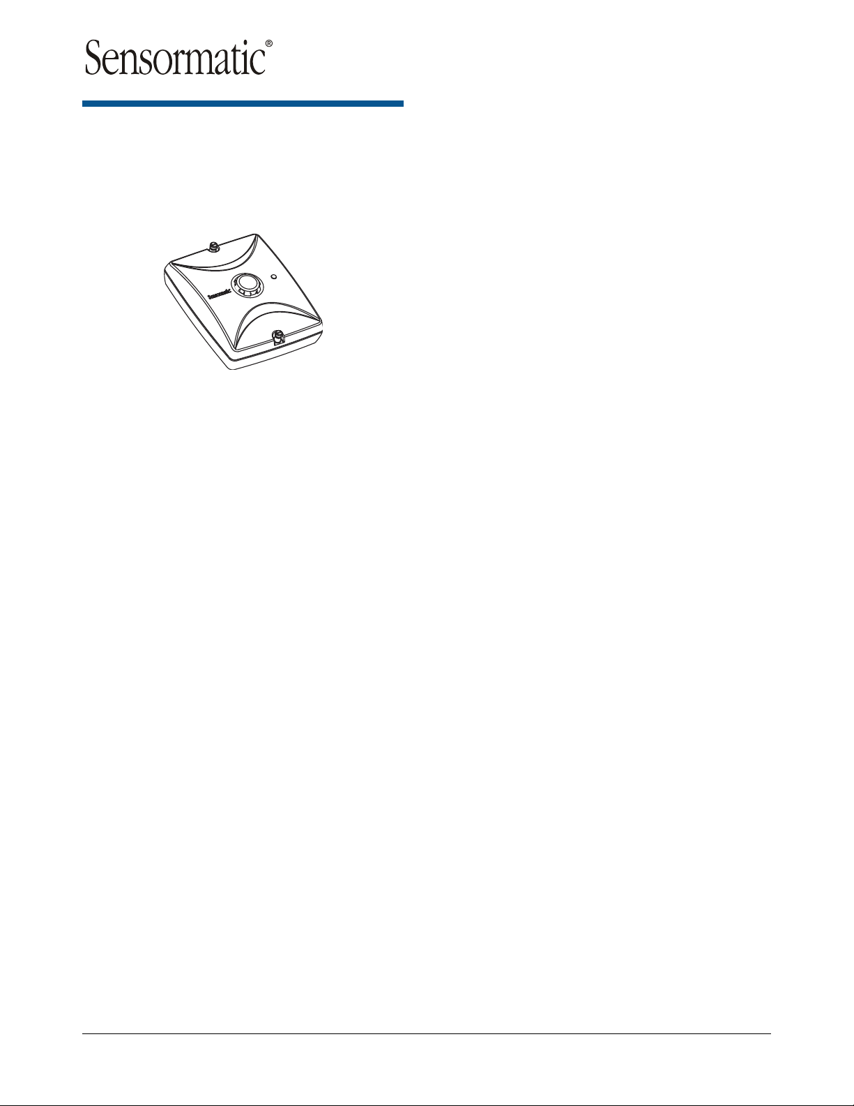
The ZBAMB4300 Sync Access Point (Sync AP) is
an AC line zero-crossing detector that can transmit
zero crossing data to nearby ZBAMB2070 Mobile
Handheld Deactivators to prevent detection
interference with nearby EAS detectors.
This guide explains only how to install the Sync AP
in a Lowe’s hardware store. For setup instructions,
see ZBAMB4300 Sync AP Connection and Setup
Guide 8200-0958-06.
If you need assistance...
Contact your Sales Representative.
ZBAMB4300 SYNC ACCESS POINT 8200-0958-03, REV. 2B
INSTALLATION GUIDE
1 of 7
Page 2
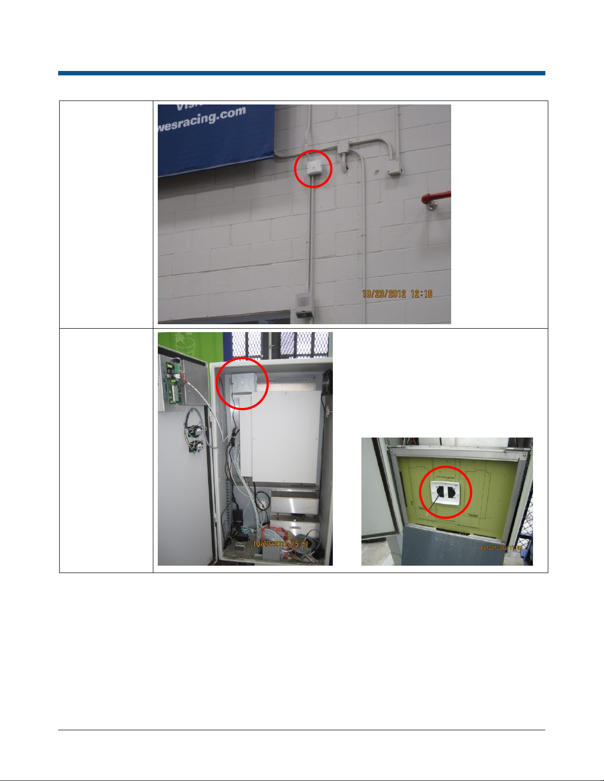
Installation Locations
On the wall near
the main or lumber
entrance
In the Universal
Outdoor Enclosure
near the garden
center entrance.
OR
ZBAMB4300 SYNC ACCESS POINT 8200-0958-03, REV. 2B
INSTALLATION GUIDE
2 of 7
Page 3

Safety
Part
Qty.
Part Number
Power Supply Module*
1
5606-0079-01
Install Kit (indoor install only)
1
0352-0580-01
Connector, Female, RJ45
1
2109-0717-01
Cable, Cat5, 4.6m (15ft)
1
6003-0266-02
Coupler, Female-to-Female, Cat5
1
2109-0906-01
Part
Qty.
Part Number
Install Kit (for outdoor enclosure)
1
0352-0591-01
Bracket, Mounting
1
0505-1544-01
Bracket, Corner/Wall Mount
1
0500-7844-01
Screw, Self-Tapping, PHP,
#6x34in
4
2816-7634-32
Screw, Tapcon, HXWH,
3/16x3/4in
4
2816-7683-02
Drill Bit, Tapcon, 5/32x3-1/2in
1
2816-7683-10
Anchor, HLW Wall, ¼-20, 1/8-5/8
4
2880-0025-02
Screw, Mach, M3x8, PHP (not
used)
1
5801-1051-120
Screw, Self-Tapping, 8x32, PHP
4
5810-5091-120
Nut, Locking, M3 (not used)
2
5826-0200-020
Nut, Locking, M4
4
5826-0300-020
Part
Qty.
3/4-inch Conduit, Preferred (as required)
–
4x4 Electrical Box, Deep
1
Parts Required
WARNING:
Install the AP in an air space not used
for environmental air. DO NOT install
it in a plenum or other environmental
air-handling space.
Cables placed in environmental
airspace must be plenum rated unless
the cables are in raceways.
All wiring must be through conduit.
Ensure that all safety instructions
within this manual are continuously
observed and respected during the
installation and/or operation of this
device.
Mount the AP only as shown in this
guide. Mounting the module any other
way may affect its operation.
The manufacturer is not responsible
for any radio or TV interference
caused by unauthorized modifications
to this equipment. Such modifications
could void the user’s authority to
operate the equipment.
Supplied
* Includes power cord 0352-0547-xx.
Not Supplied (Order Separately)
The antennas used for this transmitter
must be installed to provide a
separation distance of at least 20cm
(8in) from all persons and must not be
collocated or operating in conjunction
with any other antenna or transmitter.
Purchase
ZBAMB4300 SYNC ACCESS POINT 8200-0958-03, REV. 2B
INSTALLATION GUIDE
3 of 7
Page 4

Installation A:
3.7M (12FT)
FROM FLOOR
Main
Electrical
Box
UltraLink
Enclosure
Alarm
Module
1
2 3 4 5
Do not connect.
Leave the cable
hanging inside the
Sync AP
Main/Lumber Entrance
For the garden center entrance, see Installation B.
Electrical Connection Points
The electrical connections near the EAS system
are generally the same, but may vary from store to
store. A typical scenario is described below.
Power Cable Route
The power cable route goes from:
The AC outlet inside the main electrical box in
which the power supply module (1) and femaleto-female coupler (2) reside.
Down through existing conduit into the UltraLink
enclosure below.
Up through existing conduit and alarm module
electrical box (3).
To a 4x4 electrical box (4) mounted 3.7m (12ft)
from the floor (the Sync AP mounts here using
two screws as shown below). A length of
conduit (5) will need to be added for power to
reach this box.
Notes:
The 4.6m (15ft) Cat5 cable supplied is used to get
power to the Sync AP.
DO NOT connect this cable to the Sync AP or the
female-to-female coupler inside the main electrical
box at this time. These connections will be done at
the end of the setup process.
If the cable does not fit through the conduit, then
cut off one of its connectors close to the end of the
cable, route the cable, then reattach the connector
(see page 5 for reattachment instructions).
ZBAMB4300 SYNC ACCESS POINT 8200-0958-03, REV. 2B
INSTALLATION GUIDE
4 of 7
Page 5

Installation B:
Pin
Wire Color
1
Orange/White
2
Orange
3
Green/White
4
Blue
5
Blue/White
6
Green
7
Brown/White
8
Brown
Pin 1
Garden Center Entrance
For the main/lumber entrance, see Installation A.
Electrical Connection Points
The location of electrical connection points near
the EAS system is generally the same for each
store, but details may vary from store to store.
These instructions cover a typical scenario.
Sync AP Mounting Location
Mount the Sync AP in the Universal Outdoor
Enclosure.
If the enclosure has a drop-down floor-max
fiberglass panel: Drill an access hole in the
fiberglass for the cable and mount the Sync AP
where shown. Plug the power supply into the
AC outlet in the enclosure and route its cable up
through the drop-down panel and through the
access hole.
DO NOT connect the cable to the Sync AP. This
will be done during the setup process.
If the enclosure DOES NOT have a drop-
down floor-max fiberglass panel: Mount the
Sync AP in the interior upper-left corner of the
enclosure using optional mounting bracket
0505-1544-01* and four screws. Plug the power
supply into the AC outlet in the enclosure and
route its cable up behind the bracket. Attach the
Sync AP to the bracket using two screws and
connect the cable to the Sync AP.
DO NOT connect the cable to the Sync AP. This
will be done during the setup process.
- OR -
RJ45 Pin Assignments
* Order Sync AP Mounting Bracket Install Kit 0352-
0591-01.
Male plug pin assignments are according to the
T-568B standard. All connections are “straight
through” from plug to plug, that is: pin 1 to pin 1,
pin 2 to pin 2, and so on
ZBAMB4300 SYNC ACCESS POINT 8200-0958-03, REV. 2B
INSTALLATION GUIDE
5 of 7
Page 6

Specifications
Declarations
Electrical
AC input ........................................ 100–240V @ 47-63Hz
DC Input ................................................... 18Vdc @ 1.7A
Radio Module
Data communication:
Wireless .......................................................... 802.15.4
Data rate ........................................................ 250Kbps
Frequency range ............................. 2.4GHz ISM band,
2405MHz–2480MHz
Output power............ 5mW, +7dBm Max. (boost mode)
Spreading technique .............. Direct Sequence Spread
Spectrum (DSSS)
EAS synchronization ............................... Wireless EAS
Sync-AP receiver
with internal antenna
Under Industry Canada regulations, this radio transmitter may
only operate using an antenna of a type and maximum (or
lesser) gain approved for the transmitter by Industry Canada.
To reduce potential radio interference to other users, the
antenna type and its gain should be so chosen that the
equivalent isotropically radiated power (e.i.r.p.) is not more than
that necessary for successful communication.
Conformément à la réglementation d’Industrie Canada, le
présent émetteur radio peut fonctionner avec une antenne d’un
type et d’un gain maximal (ou inférieur) approuvé pour
l’émetteur par Industrie Canada.
Dans le but de réduire les risques de brouillage radioélectrique
à l’intention des autres utilisateurs, il faut choisir le type
d’antenne et son gain de sorte que la puissance isotrope
rayonnée équivalente (p.i.r.e.) ne dépasse pas l’intensité
nécessaire à l’établissement d’une communication satisfaisante.
Antenna: 2.4GHz Internal (inverted F type PCB trace)
Environmental
Operating temperature ................. 32 to 122°F (0 to 50°C)
Relative humidity ..................... 0 to 90% non-condensing
Mechanical
Length .................................................... 13.995cm (5.5in)
Width ..................................................... 11.495cm (4.5in)
Depth ....................................................... 4.291cm (1.7in)
Weight ................................................. 0.24kg (0.536 lbs)
Regulatory Information
FCC ID: BVCAMB43
NOTE: This equipment has been tested and found to comply
with the limits for a Class B digital device, pursuant to part 15 of
the FCC Rules. These limits are designed to provide reasonable
protection against harmful interference in a residential
installation. This equipment generates, uses and can radiate
radio frequency energy and, if not installed and used in
accordance with the instructions, may cause harmful
interference to radio communications. However, there is no
guarantee that interference will not occur in a particular
installation. If this equipment does cause harmful interference to
radio or television reception, which can be determined by
turning the equipment off and on, the user is encouraged to try
to correct the interference by one or more of the following
measures: reorient or relocate the receiving antenna, increase
the separation between the equipment and receiver, connect
the equipment into an outlet on a circuit different from that to
which the receiver is connected, and/or consult the dealer or an
experienced radio/TV technician for help.
IC ID: 3506A-AMB43
Models: ZBAMB4300
This device complies with Industry Canada licence-exempt RSS
standard(s). Operation is subject to the following two conditions:
(1) this device may not cause interference, and (2) this device
must accept any interference, including interference that may
cause undesired operation of the device.
Le présent appareil est conforme aux CNR d’Industrie Canada
applicables aux appareils radio exempts de licence.
L’exploitation est autorisée aux deux conditions suivantes : (1)
l’appareil ne doit pas produire de brouillage, et (2) l’utilisateur de
l’appareil doit accepter tout brouillage radioélectrique subi,
même si le brouillage est susceptible d’en compromettre le
fonctionnement.
This Class B digital apparatus complies with Canadian ICES-
003.
Cet appareil numérique de la classe B est conforme à la norme
NMB-003 du Canada.
EMC ....................................................... 47 CFR, Part 15
ICES-003
RSS-Gen
RSS-210
Safety .................................. UL 60950-1 (second edition)
CSA C22.2.60950-1
EN 60950-1
ZBAMB4300 SYNC ACCESS POINT 8200-0958-03, REV. 2B
INSTALLATION GUIDE
6 of 7
Page 7

Other Declarations
WARRANTY DISCLAIMER: Sensormatic Electronics, LLC
makes no representation or warranty with respect to the
contents hereof and specifically disclaims any implied
warranties of merchantability or fitness for any particular
purpose. Further, Sensormatic Electronics, LLC reserves the
right to revise this publication and make changes from time to
time in the content hereof without obligation of Sensormatic
Electronics, LLC to notify any person of such revision or
changes.
LIMITED RIGHTS NOTICE: For units of the Department of
Defense, all documentation and manuals were developed at
private expense and no part of it was developed using
Government Funds. The restrictions governing the use and
disclosure of technical data marked with this legend are set
forth in the definition of “limited rights” in paragraph (a) (15) of
the clause of DFARS 252.227.7013. Unpublished - rights
reserved under the Copyright Laws of the United States.
TRADEMARK NOTICE: Sensormatic is a registered trademark
of Sensormatic Electronics, LLC. Other product names
mentioned herein may be trademarks or registered trademarks
of Sensormatic or other companies.
No part of this guide may be reproduced in any form without
written permission from Sensormatic Electronics, LLC.
ZBAMB4300 SYNC ACCESS POINT 8200-0958-03, REV. 2B
INSTALLATION GUIDE
7 of 7
 Loading...