

Page 1

RM2-4000-PI26 Reader
DRAFT
RM2L-4000-PI26 Reader
Installation Guide
Version A0
Document Part Number 8200- 1179-01
September 2015
OVERVIEW
NOTE The RM2-4000-PI26 reader model is UL294 approved and not UL1076 approved.
This guide provides installation and connection information for RM2-4000-PI26 and
RM2L-4000-PI26 Readers.
The RM2L-4000-PI26 reader model is both UL294 and UL1076 approved.
Reader Models
The RM readers provide an enclosed RM-4 board with multiple read heads. The readers
include two separate read heads in their enclosure – a multi-technology read head
positioned behind the right hand side of the reader, and a separate Indala prox read head
located behind the keypad portion of the reader. The multi-technology read head will
read both low frequency (125KHz) HID prox cards and high frequency (13.56 MHz)
smart cards.
FIGURE 1. Reader Models
RM2-4000-PI26
RM2L-4000-PI26
1
Page 2
Overview
DRAFT
TABLE 1. Part Numbers
Reader Model Part Number
With keypad; built-in RM-4 DS interface board RM2-4000-PI26
With keypad and LCD; built-in RM-4 DS interface board RM2L-4000-PI26
Supported
Technologies and Card
Formats
NOTES UL has not evaluated the ability to “flash” new card protocols or formats directly to
Proximity
(125 KHz) Formats
Supported
The RM Multi-Technology reader can read three major card technologies – HID prox,
Indala prox, and 13.56 MHz smart card. Specific card formats supported include ISO
14443 A/B serial number, ISO 15693 serial number, iCLASS® serial number, MIFARE
encrypted sector, DESFire serial number, FIPS 201 PIV-II, and most 125 KHz formats
(HID, Indala 26-bit and CASI ProxLite).
the reader.
The RM Multi-Technology reader can be used to transition from a proximity system
to a more advanced smart card system gradually over time, or to maintain the
existing proximity card system while moving selected personnel to smart cards.
UL has not evaluated Smart Card technology with this unit.
UL has evaluated the Wiegand Proximity (26-bit only) card format for this unit.
TABLE 2. Proximity (125 KHz) Formats Supported
Proximity (125 KHz) Formats Supported
HID® 26 Bit Yes
HID® Corporate 1000 Yes
As Shipped: Default Mode
(On)
HID® 36 Bit Wiegand Yes
HID® 37 Bit Wiegand Yes
Other HID® Pass-through Formats Yes
Indala 26 Bit Yes
Deister Prox SmartFrame® Yes
(GE) Casi Rusco ProxLite Yes
Kantech ioProx No
NOTE
2
Not all features have been evaluated by UL.
Page 3

Features
DRAFT
Smart Card
(13.56 MHz) Formats
Supported
TABLE 3. Smart Card (13.56 MHz) Formats Supported
Smart Card (13.56 MHz) Formats Supported
MiFARE® Sector No
MiFARE® Serial number, 32 Bit Yes
MiFARE® Serial number, 56 Bit Yes
MiFARE® Plus Serial number, 56 Bit Yes
MiFARE® DesFire Serial number, 56 Bit No
MiFARE® DesFire® EV1 Serial number, 56 Bit No
iCLASS® ISO 15693 Serial number, 64 Bit Yes
* PIV, TWIC, CAC, FASC-N Read Yes* (200-bit output)
* PIV-I, 128 Bit, GUID Yes* (if 200-bit output is
* PIV-C, 128 Bit, GUID Yes* (if 200-bit output is
* Refers to cards issued under the U.S. Government Smart Card Initiative, HSPD-12.
Enabled by Default?
enabled)
enabled)
NOTE
FEATURES
NOTE
Not all features have been evaluated by UL.
Universal compatibility with most 125 KHz Prox (including all HID® Prox formats
and Indala 26-bit), all ISO 15693, and ISO 14443A credentials (badges, disk tags
and key fobs). Reads both 125 KHz and 13.56 MHz credentials in the same reader.
Electrical protection (reverse polarity diode protection on power lines).
Data lines: high-speed transient voltage suppressor diodes.
IP65-rated sealed electronics for deployment in both interior and exterior
environments.
Beep-on-card defaults to ON.
PIV support – The reader supports a FASC-N read (low assurance read, 200-bit
output) from all major PIV, TWIC and CAC cards, plus a 128-bit output from PIV-I
and CIV cards.
MIFARE 7-byte CSN Support - The reader firmware will be able to distinguish
between a legacy MIFARE Classic card and a “next-generation” MIFARE classic
card. The next generation MIFARE cards have a unique 7-byte serial number, not 4byte. When presented to a reader, the next-gen card causes the reader to output a 56bit CSN. Older cards still output a 32-bit CSN.
Not all features have been evaluated by UL.
3
Page 4

Features
DRAFT
Controller Communications
Wiegand
Locally Flashable via RS485
Open Standards Compliance
ISO 14443A
ISO 14443B
ISO 15693
Configure Using Program Card
Pass-through - Default setting that allows the reader to send all data on the card.
Fixed length - Reader can be configured to output a fixed length by padding or
truncating data on the card.
(26-bit, 32-bit, 35-bit, 37-bit, 64-bit)
CASI ProxLite
44-bit pass-through
MIFARE sectors
Select a sector (0-15)
Customize encryption keys
Specify data format (number of bits output)
Enable PIN-on Smart Card functionality
FIPS 201 PIV-II
Customize FASC-N Weigand BCD output
75-bit
128-bit
200-bit (default)
Customize the HMAC by changing the site key
Output HMAC
Output expiration date
4
Page 5
SPECIFICATIONS
DRAFT
Specification Requirement
Data Cable Recommended data cable is Belden #9841or equivalent.
Power Wiring Recommended power wiring is Belden #8461/8442 twisted
Specifications
The maximum length is 4000 feet (1212 meters) between
the controller and the reader.
pair. Maximum length depends on the wire gauge. Readers
can be powered from a local power supply.
Temperature
Distance from P5 to the ARM-1 Maximum: 25 feet
Distance from P5 to the inputs Maximum: 2000 feet
1KW resistors for the NO and NC
supervised inputs
Shielded, minimum 22 AWG stranded,
twisted pair cable
Power Requirements
NOTES Reader power to be supplied from power limited output of a Listed control unit or
Indoor: 32° F to 120° F (0° C to 49° C)
Outdoor: -31° F to 151° F (-35° C to 66° C)
Reader Display: 14° F to 151° F (-10° C to 66° C)
Display with heater kit: -4° F to 151° F (-20° C to 66° C)
Locate as close as possible to the switch.
Must be used to comply with UL.
from a separately-supplied UL Listed, access control (UL294) or burglar alarm
(UL603), power-limited power source with 4-hour standby capability.
Connection to the ARM-1 has not been evaluated by UL.
TABLE 4. Reader Power Supply Requirements
Reader Power Requirements: 12 VDC
RM2-4000-PI26
With Keypad
RM2L-4000-PI26
With Keypad and LCD
Relay contact power limits Up to 30 VAC/DC, 3.3 A maximum
350 mA Max
Voltage Range: 12V
350 mA Max
Voltage Range: 12V
5
Page 6
Installation
Standard H
DRAFT
INSTALLATION
Install the RM Mount
Plate
To Install the Reader:
1. Install the reader mount plate.
2. Wire the components.
3. Connect and ground the cable shields on the reader bus.
(Refer to TAB 2010-15 “RM Reader ESD Protection Guidelines.”)
4. Set the reader address.
5. Install the ARM-1 relay boards (optional).
6. Install the heater kit (optional).
7. Mount the reader standard housing on the reader mount plate using the Software
House security screwdriver (Part number 132-183).
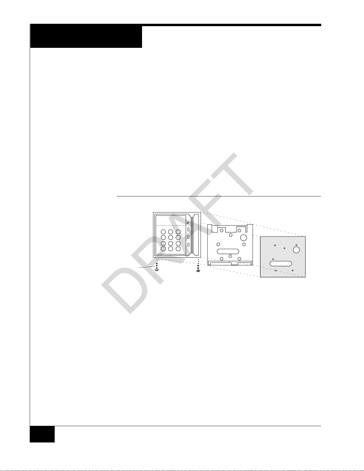
Figure 2 shows the standard housing, mount plate, and gasket. The readers conform to
the same housing, mount plate, and gasket dimensions.
FIGURE 2. Standard Housing and Mount Plate
ousing
6
Housing
screws
Requires a security screwdriver
Figure 3 on page 7 shows the mount plate dimensions.
Standard mount plate
Gasket
Page 7

FIGURE 3. Mount Plate Dimensions
DRAFT
5.45"
Installation
Wiring
access
2.47"
1.29"
.83"
1.54"
1.82"
2.73"
3.64"
3.92"
This device has been approved for outdoor use when properly installed with the
RM Heater Kit Installation (P.N. 130-915) and the supplied gasket material.
Position the gasket with the RM mount plate so that the mounting holes are
properly aligned. Ensure that the gasket is placed between the mounting surface
and mating surface of the RM mount plate. Fasten the RM mount plate to the
mounting surface with the gasket material in between. Install the gasket so that
no gaps or wrinkles are present.
The RM mount plate contains eight mounting holes. However, you do not have to
use all eight holes; usually any four of the eight holes are adequate. The
mounting holes are 0.156” and provide clearance for 6-32 flat head counter sunk
bolts or screws.
8 mounting holes
.0.156" Thru, 0.280” Countersink
4.11"
3.66"
4.94"
7
Page 8

Installation
DRAFT
Wiring the Reader
Components
Figure 4 shows reader connections.
FIGURE 4. Reader Connection
NOTE
UL has not evaluated the ARM-1.
8
Page 9

Setting up the reader
DRAFT
Wiring the Inputs,
Outputs, Reader Bus
Figure 5 shows RM-4 P1 and P5 wiring.
FIGURE 5. RM-4 Wiring Requirements
NOTES SW3-7 and SW3-8 refer to the Beeper on the RM-4.
SETTING UP THE
READER
P3 BEEP refers to the Beeper on the read head, if it exists. There is no Beeper on the
reader read heads. Some third-party readers that are connected to a standalone reader
have beepers.
To Set Up the Reader:
1. Set the Reader Address Switch, SW1 (a 16 position rotary switch, see Figure 5), to a
number from one to eight. Each Reader along the bus must have a unique address.
2. The SW3-1, SW3-2, SW3-3, and SW3-6 Configuration Switches are factory preset
for the readers, as shown in Figure 5 on page 9.
3. Note that you can override SW3-4, SW3-5, SW3-7 and SW3-8 if desired.
To properly terminate an RS-485 line, only the last unit on the bus should have
SW3-5 in the On (closed) position.
9
Page 10

Setting up the reader
DRAFT
Grounding and
Shielding
Single RM Reader
When connecting a single RM reader to the reader bus, use twisted pair, shielded
minimum 24 AWG cable. Attach the shield at the controller end.
(Refer to TAB 2010-15 “RM Reader ESD Protection Guidelines.”)
Attach a local earth ground (18 or 22 gauge) wire to the J5 component on the RM
reader.
Multiple RM Bus Devices
When wiring an RM reader to a bus with multiple devices, such as other RM-4s, I/8s, or
R/8s:
Attach the shields along the bus together (insulate each connection). Snip off the
shield wire at the end of the bus, see Figure 6.
Attach the shield to the ground at only one point – at the ground stud inside the
controller
Attach a local earth ground (18 or 22 gauge) wire to the J5 component on the RM
reader.
FIGURE 6. Reader Shield Wiring
Twist shield wires together and insulate
Ground stud
(do not ground)
Setting Module
Address and
EOL Termination
Shield wire
Shield wire
Knockout
RS-485 connector on a reader
(bus configuration)
Enclosure/cabinet
To set the module address, set SW1 (16 position rotary switch) to a number from one to
eight. Every reader on a bus must have a unique address.
To set RS-485 EOL (End of Line) termination, set SW3-5 to the On (closed) position if
the module is the last unit on the bus. If the module is not the last unit on the bus,
SW3-5 should be Off (open).
Snip off shield
wire at end of
bus
10
Page 11

Setting up the reader
DRAFT
Figure 7 shows how to connect ARM-1 relay modules to the reader outputs and how to
wire NO (Normally Open) and NC (Normally Closed) supervised inputs.
FIGURE 7. Reader Input/Output Connections
Installing the ARM-1
Relay Module
Two ARM-1 relay components can be connected to the reader through the P5 connector
(Table 5 ).
RM P5-1 is the common (+12 VDC) pin for either ARM-1.
RM P5-2 is the output drive (GND) for the first relay.
RM P5-3 is the output drive (GND) for the second relay.
TABLE 5. ARM-1 Wiring
Module (131-192) Wiring
ARM-1 Relay ARM P2-1 to RM P5-1
ARM P2-2 to RM P5-2
ARM-2 Relay ARM P2-1 to RM P5-1
ARM P2-2 to RM P5-3
11
Page 12

Setting up the reader
DRAFT
Installing the Heater
(optional)
The readers require a heater kit (Model C130-915) when installed outdoors in an
environment where temperatures may drop below 40° F (5° C).
The Model C130-915 heater kit contains the following parts:
TABLE 6. Heater Parts
Quantity Description
1 Transformer 12 VAC 40VA
2 Heater Strips
1 Thermostat (turns on at 40 ° F)
3 Wire nuts
2 6-32 x 1/4” screws to mount thermostat to RM
plate.
Part number C130-915A is supplied without a transformer. A UL Listed Class 2
transformer rated output 12 VAC, 40 VA is required for proper installation.
Figure 8 shows how to wire the RM heater kit.
FIGURE 8. RM Heater Kit Wiring
Figure 9 on page 13 shows the location of the heater strips and thermostat on the RM
mount plate.
12
Page 13

Setting up the reader
DRAFT
FIGURE 9. RM Installation
.
Applying Heater Strips
To Apply Heater Strips:
1. Clean the attachment surface of the RM mount plate with a solvent such as alcohol
(use all required precautions when handling solvents).
2. Carefully remove the release film from the adhesive.
3. Locate the heater on the clean surface of the RM mount plate exactly as shown in
Figure 9.
4. Gently roll the heater strip in place to remove air bubbles.
5. For maximum adhesion, do not apply pressure to the heater strips for 72 hours.
NOTE Air gaps or bubbles under the heater cause localized overheating and possible heater
burnout. Also, application of adhesives at temperatures below 50° F is not
recommended.
Installing the Thermostat
To Install the Thermostat:
1. Fasten the thermostat to the RM mount plate with the body of the device facing the
junction box and the face sitting flat against the RM mount plate surface.
2. With the back (or outside) surface facing up, align the thermostat such that the screw
holes of the thermostat allow for the 6-32 x 1/4” screws to secure the device to the
RM mount plate.
3. Use two (Quantity 2) 6-32 x 1/4” screws to mount the thermostat to the RM mount
Plate. Tighten the screws allowing the thermostat to be sufficiently secured to the
RM mount plate. Do not over tighten the screws.
13
Page 14

Testing Readers
DRAFT
TESTING READERS
To Test the Readers:
1. Properly configure Readers, Inputs, and Outputs using the C•CURE Administration
application and put the reader Online.
2. Measure the supply voltage to the reader.
The voltage can be measured between pin 1 (+12 VDC supply) and pin 4 (ground)
on the P4 connector. The voltage must be +12 VDC (+/-5%).
3. Check the reader address setting.
The reader must be set to an unused address, between 1 and 8, when connected to
the apC or iSTAR. Use rotary switch SW1 to set the reader address.
4. Check the reader for communications to the controller by observing LED2 and
LED3. (RM2L-4000-PI26 only)
5. Check the supervised inputs. Configure the inputs on the controller using the
C•CURE Administration application.
With no switches or resistors connected to the supervised input 1 and 2 lines, the
C•CURE Monitoring application should report inputs as “Open Loop”. When you
connect the 1,000-ohm resistor to the input terminals, the C• CURE Monitoring
application should report that the input as “Deactivated”. Supervised inputs #1 is
found at pins 4 and 5 of P5. Supervised input #2 is found at pins 6 and 7 of P5.
6. Check the outputs.
The outputs can be functionally tested by using the “momentary activate” feature in
the C• CURE Monitoring application. When the outputs are momentarily activated,
the signal will change state for a few seconds.
An RM2L-4000-PI26 and RM2L-NH can be used in area/partition for signal
acknowledgement.
CONFIGURATION
NOTES
14
7. Check the reader interface.
The reader interface can only be tested by presenting a card with the appropriate
technology to the reader. Reading a card will cause the display to show “Access
Granted” or “Access Denied,” depending on the clearance of the card.
The change to the default reader settings requires the use of special program cards that
are available from the Software House Applications Department. Program cards are
used to set a specific MIFARE read key and change other settings including card
technologies to be read.
To Program a Card Reader:
1. Power cycle the reader.
2. Present the .INI card. The reader’s internal amber LED turns off within the read head
compartment to indicate the reader is ready for the first program card.
3. Present the first program card. The amber LED turns on solid.
Page 15

Configuration Notes
DRAFT
4. If there are more program cards, repeat steps 2 and 3 until you have presented the
necessary number of program cards.
5. The reader is configured for the specified option(s) and is ready for use.
Amber LED
Flash Upgrade
For information about upgrading the firmware revision, refer to the PDF document
entitled SWH Readers Download Firmware to Reader posted on the Software House
Member Center.
15
Page 16

Compliance
DRAFT
Compliance
Specification Description
UL294 5
UL1076 5
IEC60950-1 ITE – Safety International
EN60950 ITE – Safety EU
EN55022-:2010 ITE – Radio Disturbance Characteristics EU
EN55024 ITE – Immunity Characteristics EU
EN50130-4:2011
IEC 62599-2
RoHS Restriction of hazardous substances EU
FCC 47 CFR part 15 FCC – unintentional transmitter USA - Class A
ICES-003/NMB-003 Issue 5 Canada – unintentional transmitter Canada - Class A
AS/NZS CISPR 22:2009 ITE – Radio Disturbance Characteristics Australia/New Zealand
Canadian Radio
Emissions
Requirements
th
Edition
th
Edition
This digital apparatus does not exceed the Class A limits for radio noise emissions from
digital apparatus set out in the Radio Interference Regulations of the Canadian
Department of Communications.
Le present appareil numerique n’emet pas de bruits radioelectriques depassant les
limites applicables aux appareils numeriques de la class A prescrites dans le Reglement
sur le brouillage radiolelectrique edicte par le ministere des Communications du
Canada.
Access Control System USA
Proprietary Alarm Units USA
Alarm systems – Electromagnetic Compatibility EU
United States
16
This equipment has been tested and found to comply with the limits for a Class A digital
device, pursuant to Part 15 of the FCC Rules. These limits are designed to provide
reasonable protection against harmful interference when the device is operated in a
commercial environment. This equipment generates, uses, and can radiate radio
frequency energy and, if not installed and used in accordance with the instruction
manual, may cause harmful interference to radio communications. Operation of this
equipment in a residential area is likely to cause harmful interference in which case the
user will be required to correct the interference at his/her own expense.
CAUTION: Equipment changes or modifications without the approval of the party
responsible for compliance could void the user's authority to operate the equipment and
could create a hazardous condition.
Page 17

UL Listing
DRAFT
The following requirements must be adhered to:
RM2L-4000-PI26 and RM2-4000-PI26 readers are Underwriters Laboratories
Inc. (UL) Listed to Standard UL 294, Access Control System Units.
RM2L-4000-PI26 reader is Underwriters Laboratories Inc. (UL1076).
The RM2-4000-PI26 and the RM2L-4000-PI26 readers installed in accordance
with the National Electric Code (ANSI/NFPA 70) or the Canadian Electric
Code as required by local authorities.
When purchased modularly, the reader module assembly is only for field
replacement in the RM housing.
Important Safety Information
Important Safety Information
LIFE SAFETY REQUIREMENT:
A fail-safe mechanism override must be installed at each card reader exit to allow people to leave the secure
area in case of electromechanical device failure.
2002/96/EC (WEEE directive):
Products marked with this symbol cannot be disposed of as unsorted municipal waste in the European Union.
For proper recycling, return this product to your local supplier upon the purchase of equivalent new equipment,
or dispose of it at designated collection points.
C•CURE and Software House are trademarks of Tyco Security Products.
The trademarks, logos, and service marks displayed on this document are registered in the United States [or other
countries]. Any misuse of the trademarks is strictly prohibited and Tyco will aggressively enforce its intellectual
property rights to the fullest extent of the law, including pursuit of criminal prosecution wherever necessary. All
trademarks not owned by Tyco are the property of their respective owners, and are used with permission or allowed
under applicable laws.
Product offerings and specifications are subject to change without notice. Actual products may vary from photos.
Not all products include all features. Availability varies by region; contact your regional sales manager.
Document Number: 8200-1179-01
Revision: A0
Release Date: September 2015
This manual is proprietary information of Software House. Unauthorized reproduction of any portion of this manual
is prohibited. The material in this manual is for information purposes only. It is subject to change without notice.
Software House assumes no responsibility for incorrect information this manual may contain.
©2015 Tyco Security Products
All Rights Reserved.
17
Page 18

DRAFT
 Loading...