

Page 1
Technical Services
800-381-9312 | +1-401-781-8220
www.tyco-fire.com
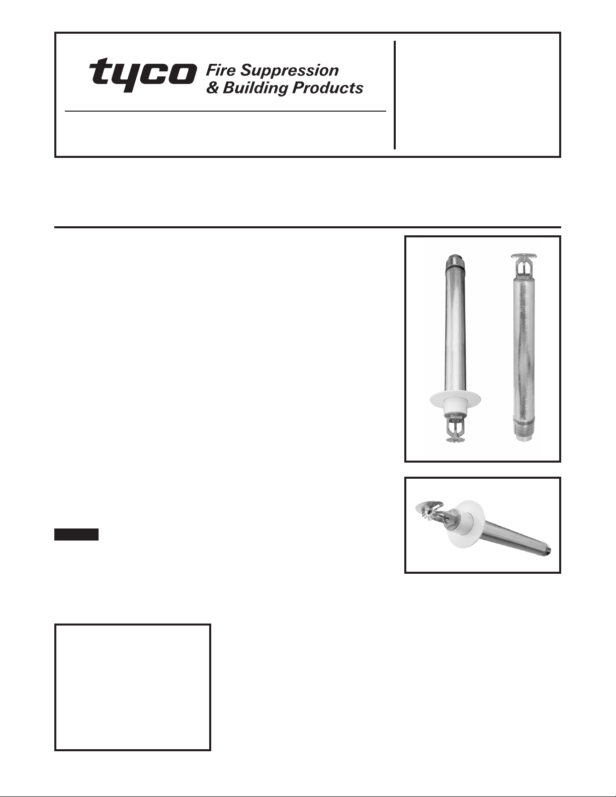
Series DS-1 Dry-Type Sprinklers
Quick Response, Standard Coverage
5.6 K-factor, 3/4 and 1-Inch NPT
General
Description
The TYCO Series DS-1, 5.6 K-factor,
3/4 and 1-Inch NPT, Quick Response,
Standard Coverage, Dry-Type Sprinklers are decorative, 3-mm glass bulb
automatic sprinklers de signed for commercial use. Dry-Type Sprinklers are
typically used where:
•
pendent sprinklers are re quired on
dry pipe systems that are exposed to
freezing tempera tures; for example,
sprinkler drops from un heated portions of buildings.
•
sprinklers and/or a portion of the connecting piping are exposed to freezing
temperatures; for example, sprinkler
drops from wet sys tems into freezers,
sprinkler sprigs from wet systems into
unheated attics, or horizontal piping
extensions through a wall to protect an
unheated areas such as loading docks,
overhangs, and building exteriors.
•
sprinklers are used on sys tems that are
seasonally drained to avoid freezing;
for example, vacation areas.
jurisdiction. Failure to do so may impair
the performance of these de vices.
Owners are responsible for maintain ing
their fire protection system and de vices
in proper operating condition. The installing contractor or sprinkler manufacturer should be contacted with any
questions.
The Series DS-1 Dry-Type Sprinklers
must only be installed in fittings that
meet the requirements of the Design
Criteria section.
Model/Sprinkler
Identification
Numbers (SINs)
3/4-Inch NPT:
TY3935 - Pendent
TY3735 - Horizontal Sidewall
1-Inch NPT:
TY3235 - Pendent
TY3135 - Upright
TY3335 - Horizontal Sidewall
NOTICE
The Series DS-1 Dry-Type Sprinklers
described herein must be installed
and maintained in compliance with this
document, as well as with the applicable standards of the National Fire
Protection Association, in addition to
the standards of any authorities hav ing
Always refer to Technical Data
Sheet TFP700 for the “INSTALLER
WARNING” that provides cautions
with respect to handling and installation of sprinkler systems and
components. Improper handling and
installation can permanently damage a sprinkler system or its components and cause the sprinkler to fail
to operate in a fire situation or cause
it to operate prematurely.
IMPORTANT
Page 1 of 10 OCTOBER 2010 TFP510
Page 2
TFP510
Page 2 of 10
3/4-INCH NPT
TY3935 Pendent
with Standard
Recessed Escutcheon
(Figure 4)
TY3935 Pendent
with Standard Escutcheon
(Figure 3)
with Deep Escutcheon
(Figure 5)
without Escutcheon
(Figure 6)
TY3735 Horizontal Sidewall
with Top of Deflec tor-to-Ceiling
Dist ance of 4 to 12 inches
(100 to 30 0 mm)
with Standard Escutcheon
(Figure 8)
with Deep Escutcheon
(Figure 9)
without Escutcheon
(Figure 10)
Temperature
Rating
Bulb
Color Code
Natural
Bras s
Chrome
Plate d
White
Polyester
Natural
Bras s
Finish
Chrome
Plate d
White
Polyester
Natural
Bras s
Chrome
Plate d
135°F (57°C) Orange 1, 2 1, 2 1*, 2*
155°F (68°C) Red 1, 2 1, 2 1*, 2*
175°F (79°C) Yellow 1, 2 1, 2 1*, 2*
200°F (93°C) Green 1, 2 1, 2 1*, 2*
286°F (141°C) Blue N/A 1, 2 1*, 2*
Notes:
1. Listed by Underwriters Laboratories, Inc.
(maximum order length of 48 inches).
2. Listed by Underwriters Laboratories for use in
Canada (maximum order length of 48 inches).
* Light and Ordinary Hazard Occupancies Only / N/A - Not Available
TABLE A
3/4-INCH NPT, SERIES DS-1 QUICK RESPONSE, STANDARD COVERAGE DRY-TYPE SPRINKLERS
LABORATORY LISTINGS AND APPROVALS
White
Polyester
1-INCH NPT
Temperature
Rating
Bulb
Color Code
TY3235 Pendent
with Standard
Recessed Escutcheon
(Figure 4)
Natural
Bras s
Chrome
Plate d
White
Polyester
TY3235 Pendent
with Standard Escutcheon
(Figure 3)
with Deep Escutcheon
(Figure 5)
without Escutcheon
(Figure 6)
TY3135 Upright
without Escutcheon
(Figure 7)
Finish
Natural
Bras s
Chrome
Plate d
White
Polyester
TY3335 Horizontal Sidewall
with Top of Deflec tor-to-Ce iling
Dist ance of 4 to 12 inches
(100 to 30 0 mm)
with Standard Escutcheon
(Figure 8)
with Deep Escutcheon
(Figure 9)
without Escutcheon
(Figure 10)
Natural
Bras s
Chrome
Plate d
White
Polyester
135°F (57°C) Orange 1, 2, 3 1, 2 1, 2, 3 1, 2 1*, 2*, 3** 1*, 2*
155°F (68°C) Red 1, 2, 3 1, 2 1, 2, 3 1, 2 1*, 2*, 3** 1*, 2*
175°F (79°C) Yellow 1, 2, 3 1, 2 1, 2, 3 1, 2 1*, 2*, 3** 1*, 2*
200°F (93°C) Green 1, 2, 3 1, 2 1, 2, 3 1, 2 1*, 2*, 3** 1*, 2*
286°F (141°C) Blue N/A 1, 2, 3 1, 2 1*, 2*, 3** 1*, 2*
Notes:
1. Listed by Underwriters Laboratories, Inc.
(maximum order length of 48 inches).
3. Approved by Factory Mutual Research Corporation
(maximum order length of 48 inches).
2. Listed by Underwriters Laboratories for use in Canada
(maximum order length of 48 inches).
4. The Upright Sprinkler without an Escutcheon (TY3135)
is available in 1-Inch NPT only.
* Light and Ordinary Hazard Occupancies Only / ** Light Hazard Occupancies Only / N/A - Not Available
1-INCH NPT AND ISO 7-R1, SERIES DS-1 QUICK RESPONSE, STANDARD COVERAGE DRY-TYPE SPRINKLERS
TABLE B
LABORATORY LISTINGS AND APPROVALS
Page 3
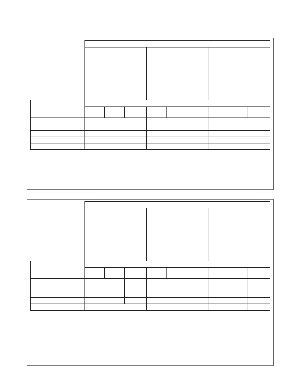
PLUG WITH
SEALING
ASSEMBLY
PLUG
SPRING
INLET
YOKE
INLET
BAND
TFP510
Page 3 of 10
Technical
Data
Approvals
UL and C-UL Listed
FM Approved
Refer to Tables A and B.
WATER
TUBE
GUIDE
TUBE
FRAME
VENT HOLE
DEFLECTOR
SPRING
CASING
INSERT
BULB
SEAT
3 mm BULB
COMPRESSION
SCREW
FIGURE 1
SERIES DS-1, 3/4-INCH NPT, QUICK RESPONSE
DRY-TYPE SPRINKLER ASSEMBLY
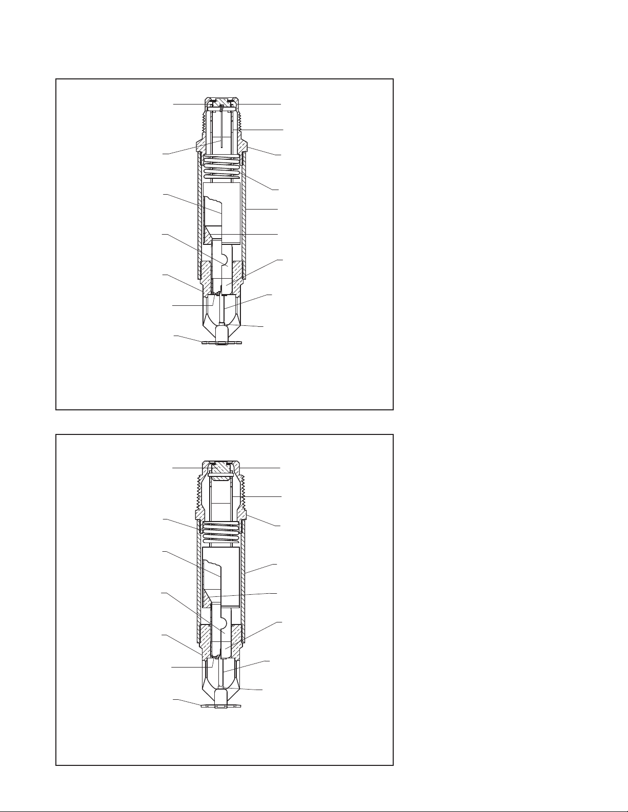
PLUG WITH
SEALING
ASSEMBLY
SPRING
WATER
TUBE
GUIDE
TUBE
FRAME
INLET
YOKE
INLET
BAND
CASING
INSERT
BULB
SEAT
Maximum Working Pressure
175 psi (12,1 bar)
Inlet Thread Connection
3/4-Inch NPT
1-Inch NPT or ISO 7-R1
Discharge Coefficient
K = 5.6 GPM/psi
(80,6 LPM/bar
1/2
1/2
)
Temperature Ratings
Refer to Tables A and B.
Finishes
Sprinkler: Natural Brass, Chrome
Plated, White Polyester
Escutcheon: White Coated, Chrome
Plated, Brass Plated
Physical Characteristics
Inlet. . . . . . . . . . . . . . . . . . . . . Copper
Plug . . . . . . . . . . . . . . . . . . . . Copper
Yoke . . . . . . . . . . . . . . Stainless Steel
Casing . . . . .Galvanized Carbon Steel
Insert . . . . . . . . . . . . . . . . . . Bronze
Bulb Seat . . . . . . . . . . .Stainless Steel
Bulb . . . . . . . . . . . . . . . . . . . . . . Glass
Compression Screw . . . . . . . . Bronze
Deector . . . . . . . . . . . . . . . . Bronze
Frame . . . . . . . . . . . . . . . . . . . Bronze
Guide Tube . . . . . . . . . Stainless Steel
Water Tube . . . . . . . . .Stainless Steel
Spring . . . . . . . . . . . . .Stainless Steel
Plug Spring*. . . . . . . . .Stainless Steel
Sealing Assembly . . . . . . . . Beryllium
Nickel w/Teon**
Escutcheon . . . . . . . . . Carbon Steel
Patents
U.S.A. Patent No. 5,188,185
**Registe red trademark of DuPont
*For 3/4- Inch NPT only
VENT HOLE
DEFLECTOR
3 mm BULB
COMPRESSION
SCREW
FIGURE 2
SERIES DS-1, 1-INCH NPT AND ISO 7-R1, QUICK RESPONSE
DRY-TYPE SPRINKLER ASSEMBLY
Page 4

TFP510
Page 4 of 10
SPRINKLER FITTING
(REFER TO DESIGN
CRITERIA SECTION)
FACE OF
SPRINKLER
FITTING
ORDER LENGTHS:
2-3/4" to 48"
(69,9 to 1219,2 mm)
IN 1/4" (6,4 mm)
INCREMENTS
FACE OF
CEILING
2-3/16" ± 1/8"
(55,6 ± 3,2 mm)
1-3/4" DIA.
(44,5 mm)
3" DIA.
(76,2 mm)
FIGURE 3
TY3235 AND TY3935 PENDENT
WITH STANDARD ESCUTCHEON
SPRINKLER FITTING
(REFER TO DESIGN
CRITERIA SECTION)
FACE OF
SPRINKLER
FITTING
ORDER LENGTHS:
3-3/4" to 48"
(95,3 to 1219,2 mm)
IN 1/4" (6,4 mm)
INCREMENTS
FACE OF
CEILING
1-3/8" ± 1/8"
(34,9 ± 3,2 mm)
2-1/4" DIA.
(57,2 mm)
2-7/8" DIA.
(73,0 mm)
FIGURE 4
TY3235 AND TY3935 PENDENT
WITH STANDARD RECESSED
ESCUTCHEON
SPRINKLER FITTING
(REFER TO DESIGN
CRITERIA SECTION)
FACE OF
SPRINKLER
FITTING
ORDER LENGTHS:
1/2" to 46"
(12,7 to 1168,4 mm)
IN 1/4" (6,4 mm)
INCREMENTS
FACE OF
CEILING
4-1/4" ± 1/8"
(108,0 ± 3,2 mm)
3-1/2" DIA.
(88,9 mm)
2-1/2" DIA.
(63,5 mm)
FIGURE 5
TY3235 AND TY3935 PENDENT
WITH DEEP ESCUTCHEON
SPRINKLER FITTING
(REFER TO DESIGN
CRITERIA SECTION)
FACE OF
SPRINKLER
FITTING
ORDER LENGTHS:
5" to 48"
(127,0 to 1219,2 mm)
IN 1/4" (6,4 mm)
INCREMENTS
MINIMUM
1-3/4" (44,5 mm)
DEFLECTOR
TO CEILING
FIGURE 6
TY3235 AND TY3935 PENDENT
WITHOUT ESCUTCHEON
TOP OF
DEFLECTOR
ORDER LENGTHS:
5" to 48"
(127,0 to 1219,2 mm)
IN 1/4" (6,4 mm)
INCREMENTS
FACE OF
SPRINKLER
FITTING
SPRINKLER FITTING
(REFER TO DESIGN
CRITERIA SECTION)
FIGURE 7
TY3135 UPRIGHT
WITHOUT ESCUTCHEON
— 1-INCH NPT ONLY —
Page 5

TFP510
Page 5 of 10
ORDER LENGTHS:
2-3/4" to 48" (69,9 to 1219,2 mm)
IN 1/4" (6,4 mm) INCREMENTS
FACE OF
SPRINKLER
FITTING
SPRINKLER FITTING
(REFER TO DESIGN
CRITERIA SECTION)
FACE OF
MOUNTING
SURFACE
FIGURE 8
TY3335 AND TY3735 HORIZONAL SIDEWALL
WITH STANDARD ESCUTCHEON
ORDER LENGTHS: FACE OF
1/2" to 45-3/4" (12,7 to 1162,1 mm)
IN 1/4" (6,4 mm) INCREMENTS
FACE OF
SPRINKLER
FITTING
SPRINKLER FITTING
(REFER TO DESIGN
CRITERIA SECTION)
FIGURE 9
TY3335 AND TY3735 HORIZONAL SIDEWALL
WITH DEEP ESCUTCHEON
ORDER LENGTHS:
5-1/2" to 48" (139,7 to 1219,2 mm)
IN 1/4" (6,4 mm) INCREMENTS
FACE OF
SPRINKLER
FITTING
SPRINKLER FITTING
(REFER TO DESIGN
CRITERIA SECTION)
FIGURE 10
TY3335 AND TY3735 HORIZONAL SIDEWALL
WITHOUT ESCUTCHEON
1-3/4" DIA.
(44,5 mm)
CENTERLINE
OF WATERWAY
MOUNTING
SURFACE
2-1/2" DIA.
(63,5 mm)
CENTERLINE
OF WATERWAY
4" ± 1/8"
(101,6 ± 3,2 mm)
3.5°
(7,9 mm)
4-13/16" ± 1/8"
(122,2 ± 3,2 mm)
3.5°
(7,9 mm)
2-1/4" (57,2 mm)
DEFLECTOR TO
CENTERLINE
OF WATERWAY
3" DIA.
(76,2 mm)
5/16"
3-1/2" DIA.
(88,9 mm)
5/16"
MINIMUM
MOUNTING
SURFACE
3.5°
(7,9 mm)
5/16"
Operation
When the TYCO Series DS-1 Dry-Type
Sprinkler is in service, water is prevented from entering the assembly by the
Plug with Sealing Assembly in the Inlet
of the Sprinkler. See Figures 1 and 2.
The glass Bulb contains a uid that expands when ex posed to heat. When the
rated tem perature is reached, the uid
expands sufciently to shatter the glass
Bulb, and the Bulb Seat is released.
The compressed Spring is then able
to ex pand and push the Water Tube as
well as the Guide Tube outward. This
action simultaneously pulls inward on
the Yoke, withdrawing the Plug with
Sealing Assembly from the Inlet and
allowing the sprin kler to activate and
ow water.
Design
Criteria
The TYCO Series DS-1 Sprinklers are
intended for use in re sprinkler systems designed in accordance with the
standard installation rules recognized
by the applicable Listing or Approval
agency; for example, UL Listing is
based on NFPA 13 requirements.
Sprinkler Fittings
Install the 3/4 or 1-inch NPT Series
DS-1 Dry-Type Sprinklers in the 3/4 or
1-inch NPT outlet or run of the following ttings:
•
malleable or ductile iron threaded tee
ttings that meet the dimensional requirements of ANSI B16.3 (Class 150)
•
cast iron threaded tee ttings that
meet the dimensional requirements
of ANSI B16.4 (Class 125).
Do not install the DS-1 Sprinklers into
an elbow ttings. The Inlet of the sprinkler can contact the interior of the elbow, potentially damaging the Inlet
seal.
The unused outlet of the threaded tee is
plugged as shown in Figures 12 and 13.
You can also install the Series DS-1
Dry-Type Sprinklers in the 3/4 or 1-inch
NPT outlet of a GRINNELL Figure 730
Mechanical Tee. However, the use of
the Figure 730 Tee for this arrangement
is limited to wet pipe systems.
The conguration shown in Figure 12
is only applicable for wet pipe systems
where the sprinkler tting and waterlled pipe above the sprinkler tting are
not subject to freezing and where the
length of the Dry-Type Sprinkler has the
minimum exposure length depicted in
Figure 11. Refer to the Exposure Length
section.
Page 6

TFP510
Page 6 of 10
For wet pipe system installations of
the 1-inch NPT Series DS-1 Dry-Type
Sprinklers connected to CPVC piping,
use only the following TYCO CPVC
ttings:
•
1" x 1" NPT Female Adapter (P/N 80145)
•
1" x 1" x 1" NPT Sprinkler Head Adapter
Tee (P/N 80249).
For wet pipe system installations of
the the 3/4-inch NPT Series DS-1
Sprinklers connected to CPVC piping, use in the 3/4" x 3/4" NPT Female
Adapter (P/N 80142).
For dry pipe system installations, use
only the side outlet of maximum 2-1/2inch reducing tee when locating the
Series DS-1 Sprinklers directly below
the branch line. Otherwise, use the conguration shown in Figure 13 to assure
complete water drainage from above
the Series DS-1 Dry-Type Sprinklers
and the branch line. Failure to do so
may result in pipe freezing and water
damage.
NOTICE
Do not install the Series DS-1 Dry-Type
Sprinkler into any other type fitting
without first consulting the Technical
Services Department. Failure to use the
appropriate fitting may result in one of
the following:
•
Failure of the sprinkler to operate properly due to formation of ice over the
inlet Plug or binding of the Inlet Plug.
•
Insufficient engagement of the Inlet
pipe threads with consequent leakage.
Drainage
In accordance with the minimum
requirements of the National Fire
Protection Association for dry pipe
sprinkler systems, branch, cross, and
feed-main piping connected to Dry
Sprinklers and subject to freezing temperatures must be pitched for proper
drainage.
Exposure Length
When using Dry Sprinklers in wet pipe
sprinkler systems to protect areas subject to freezing temperatures, use Table
C to determine a sprinkler’s appropriate
exposed barrel length to prevent water
from freezing in the connecting pipes
due to conduction. The exposed bar-
rel length measurement must be taken
from the face of the sprinkler tting to
the surface of the structure or insulation that is exposed to the heated area.
Refer to Figure 11 for an example.
Clearance Space
In accordance with Section 8.4.9.2
of the 2010 edition of NFPA 13, when
connecting an area subject to freezing and an area containing a wet pipe
sprinkler system, the clearance space
around the sprinkler barrel of Dry-Type
Sprinklers must be sealed. Due to temperature differences between two areas, the potential for the formation of
condensation in the sprinkler and subsequent ice build-up is increased. If
this condensation is not controlled, ice
build-up can occur that might damage
the dry-type sprinkler and/or prevent
proper operation in a re situation.
Use of the Model DSB-2 Dry Sprinkler
Boot, described in technical data sheet
TFP591 and shown in Figures 14 and
15, can provide the recommended seal.
Ambient Temperature
Exposed to Discharge End of
Sprinkler
40°F (4°C) 0 0 0
30°F (-1°C) 0 0 0
20°F (-7°C) 4 (100) 0 0
10°F (-12°C) 8 (200) 1 (25) 0
0°F (-18°C) 12 (305) 3 (75) 0
-10°F (-23°C) 14 (355) 4 (100) 1 (25)
-20°F (-29°C) 14 (355) 6 (150) 3 (75)
-30°F (-34°C) 16 (405) 8 (200) 4 (100)
-40°F (-40°C) 18 (455) 8 (200) 4 (100)
-50°F (-46°C) 20 (510) 10 (255) 6 (150)
-60°F (-51°C) 20 (510) 10 (255) 6 (150)
Notes:
(a) For protected area temperatures that occur between values listed above, use the next cooler temperature.
(b) These lengths are inclusive of wind velocities up to 30 mph (18,6 kph).
40°F (4°C) 50°F (10°C) 60°F (16°C)
Minimum Exposed Barrel Length, Inches (mm)
Temperatures for Heated Area
(a)
(b)
TABLE C
MINIMUM RECOMMENDED LENGTHS OF EXPOSED SPRINKLER BARRELS
IN WET PIPE SYSTEMS
Page 7

FACE OF
SPRINKLER
FITTING
HEATED
AREA
DSB-2
INTENDED
FOR FREEZER
STRUCTURES
EXPOSURE
LENGTH
(SEE DESIGN
CRITERIA
SECTION)
TO WET
SYSTEM
HEATED
AREA
DSB-2
INTENDED
FOR FREEZER
STRUCTURES
SIDE
OUTLET
PLUGGED
SPRINKLER
FITTING
(SEE DESIGN
CRITERIA
SECTION)
TO DRY
SYSTEM
AREA
SUBJECT
TO
FREEZING
TFP510
Page 7 of 10
RUN
OUTLET
PLUGGED
SPRINKLER
FITTING
(SEE DESIGN
CRITERIA
SECTION)
DSB-2
INTENDED
FOR FREEZER
STRUCTURES
FIGURE 11
EXPOSURE LENGTH
MODEL DSB-2 SPRINKLER
BOOT WITH PENDENT SERIES
DS-1 DRY SPRINKLER
SHOWN WITH
ESCUTCHEON
FIGURE 14
FIGURE 12
SPRINKLER FITTING IN
HEATED AREA
STRAP TIES
(ENDS ON
OPPOSING
SIDES OF
BOOT)
DSB-2 BOOT
ADHESIVE
1-3/4" DIA.
(44,5 mm)
CLEARANCE
HOLE
INSULATED
FREEZER
STRUCTURE
DS-1
STANDARD
SPRINKLER FITTING IN
UNHEATED AREA
1-3/4" DIA.
(44,5 mm)
CLEARANCE
HOLE
ADHESIVE
DSB-2
BOOT
STRAP TIES
(ENDS ON
OPPOSING
SIDES OF
BOOT)
INSULATED
FREEZER
STRUCTURE
DS-1
SHOWN WITH
STANDARD
ESCUTCHEON
FIGURE 15
MODEL DSB-2 SPRINKLER
BOOT WITH SIDEWALL SERIES
DS-1 DRY SPRINKLER
FIGURE 13
Page 8

TFP510
Page 8 of 10
Installation
The T YCO Series DS-1 Dry-Type
Sprinklers must be installed in accordance with the following instructions.
NOTICE
The Series DS-1 Dry-Type Sprinkler
must only be installed in fittings that
meet the requirements of the Design
Criteria section. Refer to the Design
Criteria section for other important requirements regard ing piping design
and sealing of the clearance space
around the Sprinkler Casing.
Do not install any bulb type sprinkler
if the bulb is cracked or there is a loss
of liquid from the bulb. With the sprinkler held horizontally, a small air bubble
should be present. The diameter of the
air bubble is approximately 1/16 inch
(1,6 mm) for the 135°F (57°C) rating to
1/8 inch (3,2 mm) for the 286°F (141°C)
rating.
•
Obtain a leak-tight 3/4-inch NPT sprinkler joint by applying a minimum-tomaximum torque of 10 to 20 ft. lbs.
(13,4 to 26,8 Nm).
• Obtain a leak-tight 1 inch NPT sprinkler joint by applying a minimum-tomaximum torque of 20 to 30 ft. lbs.
(26,8 to 40,2 Nm).
Higher levels of torque can distort the
sprinkler Inlet with consequent leakage
or impairment of the sprinkler.
Do not attempt to compensate for
insufcient adjustment in an
Escutcheon Plate by under or overtightening the Sprinkler. Re-adjust the
position of the sprinkler tting to suit.
1.
Install pendent sprinklers only in the
pendent position, and install upright
sprinklers only in the upright position. The deector of a pendent or
upright sprin kler must be parallel to
the ceiling.
Install horizontal sidewall sprinklers in the horizontal position with
their centerline of waterway perpendicular to the back wall and parallel to the ceiling. Ensure the word
“TOP” on the De ector faces the
ceiling.
2.
With a non-hardening pipe-thread
sealant such as Teon1 tape applied
to the Inlet threads, hand-tighten the
sprinkler into the sprinkler tting.
3.
Wrench-tighten the sprinkler using
either:
•
a pipe wrench on the Inlet Band or
the Casing (Figures 1 and 2)
•
the W-Type 7 Sprinkler Wrench on
the Wrench Flat (Figure 16).
1 Registered trademark of DuPont
Apply the Wrench Recess of the
W-Type 7 Sprinkler Wrench to the
Wrench Flat.
Note: If sprinkler removal becomes
necessary, remove the sprinkler
using the same wrenching method noted above. Sprinkler removal is easier when a non-hardening
sealant was used and torque guidelines were followed. After removal,
inspect the sprinkler for damage.
4.
After installing the ceiling or wall and
applying a celing nish, slide on the
outer piece of the Escutcheon until
it comes in contact with the ceiling
or wall. Do not lift the ceiling panel
out of its normal position.
When using the Deep Escutcheon,
hold the outer piece in contact with
the mounting surface (ceiling or
wall). Then rotate the inner piece
approximately 1/4 turn with respect
to the outer piece, to hold the Deep
Escutcheon rmly together.
Care and
Maintenance
The T YCO Series DS-1 Dry-Type
Sprinklers must be maintained and serviced in accordance with the following
instructions.
NOTICE
Before closing a fire protection system
main control valve for maintenance
work on the fire protection system that
it controls, obtain permission to shut
down the affected fire protection systems from the proper authorities and
notify all personnel who may be affected by this action.
Absence of the outer piece of an escutcheon, which is used to cover a
clearance hole, can delay the time to
sprinkler operation in a re situation.
A Vent Hole is provided in the Bulb Seat
(Figures 1 and 2) to indicate if the DryType Sprinkler is remaining dry. Evidence of leakage from the Vent Hole indicates potential leakage past the Inlet
seal and the need to remove the sprinkler to determine the cause of leakage;
for example, an improper installation
or an ice plug. Close the re protection system control valve and drain the
system before removing the sprinkler.
Exercise care to avoid dam age before,
during, and after instal lation. Never
paint, plate, coat, or otherwise alter
automatic sprinklers after they leave
the factory.
Never repaint factory-painted Cover
Plates. When necessary, replace cover plates with factory-painted units.
Non-factory applied paint can adversely delay or prevent sprinkler operation
in the event of a re.
Replace sprinklers that:
• were damaged by dropping, striking,
wrench twisting, wrench slippage, or
the like.
• were modied or over-heated.
•
have cracked bulbs or have lost liquid
from the bulbs. Refer to the Installation
Section in this data sheet.
• are leaking or exhibiting visible signs
of corrosion.
Responsibility lies with owners for the
in spection, testing, and maintenance of
their re protection system and devices
in compliance with this document, as
well as with the applicable standards of
the National Fire Protec tion Association
(for example, NFPA 25), in addition to
the standards of any other authorities
having jurisdiction. The installing contractor or sprinkler manufacturer should
be contacted relative to any questions.
Automatic sprinkler systems are recommended to be inspected, tested, and
maintained by a qualied Inspection
Service in accordance with local requirements and/or national codes.
WRENCH
RECESS
WRENCH
FLAT
PUSH WRENCH
IN TO ENSURE
ENGAGEMENT
WITH SPRINKLER
WRENCHING AREA
W-TYPE 7 SPRINKLER WRENCH
FIGURE 16
Page 9

TFP510
Page 9 of 10
Limited
Warranty
Products manufactured by Tyco Fire
Suppression & Building Products
(TFSBP) are war ranted solely to the
original Buyer for ten (10) years against
defects in mate rial and workmanship when paid for and properly installed and maintained under normal
use and service. This warranty will expire ten (10) years from date of shipment by TFSBP. No warranty is given
for products or com ponents manufactured by companies not afliated
by ownership with TFSBP or for products and components which have
been subject to misuse, improper installation, corrosion, or which have
not been installed, maintained, modied or repaired in accordance with applicable Standards of the National Fire
Protection Association, and/or the standards of any other Authorities Having
Jurisdiction. Materials found by TFSBP
to be defective shall be either repaired
or replaced, at TFSBP's sole option.
TFSBP neither assumes, nor authorizes
any person to assume for it, any other
obligation in connection with the sale of
products or parts of prod ucts. TFSBP
shall not be responsible for sprinkler
system design errors or inac curate or
incomplete information sup plied by
Buyer or Buyer’s repre sentatives.
In no event shall TFSBP be liable, in
contract, tort, strict liability or under
any other legal theory, for incidental,
indirect, special or consequential damages, including but not limited to labor
charges, regardless of whether TFSBP
was informed about the possibility of
such damages, and in no event shall
TFSBP's liability exceed an amount
equal to the sales price.
The foregoing warranty is made in lieu
of any and all other warranties, express
or implied, including warranties of merchantability and tness for a particular
purpose.
This limited warranty sets forth the exclusive remedy for claims based on failure of or defect in products, materi als
or components, whether the claim is
made in contract, tort, strict liability or
any other legal theory.
This warranty will apply to the full extent permitted by law. The invalidity, in
whole or part, of any portion of thiswarranty will not affect the remainder.
Ordering
Procedure
Contact your local distributor for availability. When placing an order, indicate
the full product name and Part Number
(P/N).
Dry-Type Sprinklers
Specify this dry-type sprinkler as
follows:
• Model/SIN from Page 1
•
Quick Response, Standard Cover age,
Dry-Type Sprinkler
• Deector Style
• 5.6 K-Factor
• Order Length
Dry-Type Sprinklers are furnished
based upon Order Length as measured per Figures 3 through 10. After
taking the measurement, round it to
the nearest 1/4 inch increment.
•
Inlet Connection: 3/4-inch NPT,
1-inch NPT, or ISO 7-R1
• Temperature Rating
• Sprinkler Finish
•
Escutcheon Style and Finish, as
applicable
• Part Number (P/N) from Table C
The Upright Sprinkler without an
Escutcheon ( TY3135) is available in
1-Inch NPT only.
Part Numbers are for 3/4-inch and
1-inch NPT stand ard order sprinklers. Orders for all other sprinkler
assemblies must be accompanied
by a complete description. Refer to
the Price List for a complete listing of
Part Numbers.
Sprinkler Wrench
Specify: W-Type 7 Sprinkler Wrench,
P/N 56-850-4-001.
Sprinkler Boot
Specify: Model DSB-2 Dry Sprinkler
Boot, P/N 63-000-0-002.
This Part Number includes one Boot,
two Strap Ties, and 1/3 oz. of Adhesive.
The quantity of adhesive is sufcient for
installing one Boot.
Page 10

TFP510
Page 10 of 10
P/N 60 – XXX – X – XXX
Pendent with Standard
01
Escutcheon (3/4" NPT)
Pendent with Deep
02
Escutcheon (3/4" NPT)
Pendent with Standard Recessed
03
Escutcheon (3/4" NPT)
Pendent without
04
Escutcheon (3/4" NPT)
Sidewall with Standard
05
Escutcheon (3/4" NPT)
Sidewall with Deep
06
Escutcheon (3/4" NPT)
Sidewall without
07
Escutcheon (3/4" NPT)
Pendent with Standard
36
Escutcheon (1" NPT)
Pendent with Deep
33
Escutcheon (1" NPT)
Pendent with Standard Recessed
37
Escutcheon (1" NPT)
MODEL/SIN
TY3935
(Figure 3)
TY3935
(Figure 5)
TY3935
(Figure 4)
TY3935
(Figure 6)
TY3735
(Figure 8)
TY3735
(Figure 9)
TY3735
(Figure 10)
TY3235
(Figure 3)
TY3235
(Figure 5)
TY3235
(Figure 4)
SPRINKLER
FINISH
1 NATURAL BRASS WHITE
4 WHITE POLYESTER WHITE
9 CHROME PLATED CHROME
0 CHROME PLATED WHITE
2 NATURAL BRASS BRASS PLATED
TEMPERATURE
RATINGS (2)
0 135°F (57°C)
1 155°F (68°C)
2 175°F (79°C)
3 200°F (93°C)
4 286°F (141°C)
ESCUTCHEON
FINISH (1)
055 5.50”
082 8.25”
180 18.00”
187 18.75”
372 37.25”
480 48.00”
SAMPLE ORDER
LENGTHS (3)
Pendent without
32
Escutcheon (1" NPT)
TY3235
(Figure 6)
NOTES
Sidewall with Standard
34
Escutcheon (1" NPT)
Sidewall with Deep
43
Escutcheon (1" NPT)
Sidewall without
44
Escutcheon (1" NPT)
Upright without
38
Escutcheon (1" NPT)
TY3335
(Figure 8)
TY3335
(Figure 9)
TY3335
(Figure 10)
TY3135
(Figure 7)
(1). Escutcheon Finish applies to sprinklers provided with
escutcheons.
(2). 286°F (141°C) temperature rating applies to non-recessed
sprinkler assemblies.
(3). Dry-Type Sprinklers are furnished based upon “Order Length”
as measured per Figures 3 through 10, as applicable, and
for each individual sprinkler where it is to be installed. After
the measurement is taken, round it to the nearest 1/4 inch
increment.
TABLE C
PART NUMBER SELECTION
SERIES DS-1, 3/4 AND 1-INCH NPT, QUICK RESPONSE, STANDARD COVERAGE, DRY-TYPE SPRINKLERS
(Use Prefix “I” for ISO 7-R1 Connection; for example, I-60-361-1-180)
Copyright © 200 9 - 2010 Tyco Fire Suppression & Building Products
. All rights reserved.
 Loading...