

Page 1

Technical Services: Tel: (800) 381-9312 / Fax: (800) 791-5500
Model DPV-1 Dry Pipe Valve, DN100 & DN150
Model ACC-1 Dry Pipe Valve Accelerator
European Conformity Valve Trim, 16 Bar
SECTIONS
General Description
DryPipeValve.........1
Accelerator . . . . . . . . . . . 1
TechnicalData..........5
Operating Principles
DryPipeValve.........9
Accelerator . . . . . . . . . . . 9
Installation ...........10
Valve Setting Procedure . . . . 10
Care and Maintenance . . . . 11
LimitedWarranty........12
Ordering Procedure . . . . . . 21
Summary Instructions . . . . . .
......... AppendicesA-G
TABLES
A - Air Pressure Requirements . 4
B - Trim Cross Reference . . . . 6
C - Accelerator Fill Times . . . 11
FIGURES
1A - DN100 Assembly . . . . . . 2
1B - DN150 Assembly . . . . . . 3
2 - Pressure Loss . . . . . . . . 4
3 - Valve Take-Out Dimensions . 5
4 - Accelerator Assembly . . . . 6
5-ValveOperation .......7
6-Accelerator“Set”.......8
7 - Accelerator “Tripped” . . . . 8
Valve Trim is illustrated in Figures
8 thru 15. Refer the Table B on
Page 5 for types of trim and corresponding figure and page number.
General
Description
DRY PIPE VALVE
The DN100and DN150, Model DPV-1
Dry Pipe Valves are differential valves
used to automatically control the flow
of water into a dry pipe fire protection
sprinkler systems upon operation of
one or more automatic sprinklers. The
DPV-1 also provides for actuation of
fire alarms upon system operation.
The Model DPV-1 features are as follows:
• External reset.
• 16 bar pressure rating.
• Unique offset single clapper design
enabling a simple compact valve to
minimize installation labor.
• Ductile iron construction to ensure a
lightweight valve to minimize shipping cost.
• A variety of inlet and outlet connections.
• Simple reset procedure through the
elimination of priming water.
Dry pipe sprinkler systems are used in
unheated warehouses, parking garages, store windows, attic spaces,
loading docks, and other areas exposedtofreezingtemperatures,where
water filled pipe cannot be utilized.
When set for service, the dry pipe
sprinklersystemispressurizedwithair
(or nitrogen). The loss of pressure
through an operated automatic sprinkler in response to heat from a fire
permits the DPV-1 Dry Pipe Valve to
open and allow a flow of water into the
sprinkler system piping. Table A establishes the minimum required system air pressure that includes a safety
factor to help prevent false operations
that occur due to water supply fluctuations.
ACCELERATOR
TheoptionalModelACC-1Accelerator
Page 1 of 22 TFP1090
MARCH, 2006
Page 2
Page2of22
TFP1090
6
7
8
9
2
CLAPPER
ASSEMBLY
11
12
13
14
15, 18
16
17
RESET
PLUNGER
PARTS
1
4
NO. QTY.DESCRIPTION REF.
1 ValveBody 1 NR
2
Air and Water
Seat
3
Handhole Cover
4 Handhole Cover
5 1/2-13 UNC x 1"
Hex Head Cap
6
Clapper
7
Clapper Facing
Clapper Facing
8
Retaining Plate
9
1/4-20 UNC x 1/2"
Socket Head Cap
10
Clapper Hinge
Pin
11
Reset Knob
12
Reset Spring
13 Reset Bushing See (c)1....
14 Reset Bushing
Reset Plunger
15
16 Reset Plunger See (c)1.....
1718Reset Latch
Subassembly 1 See (c).....
Dow Corning FS3452
Flourosilicone
3
.......
............
..........
....
.............
......
NR: Not Replaceable
CH: Common Hardware
...
1
NR
1
NR
See (b)Gasket 1..........
CHScrew 6...........
1
See (a)
1
See (a) or (b)
See (a)1....
See (a)7Screw...........
1
See (a)
1
See (c)
See (c)1.....
See (b) or (c)O-Ring 1...........
See (b) or (c)O-Ring 1..........
See (b) or (c)Grease, 1.5 g 1.....
10
5
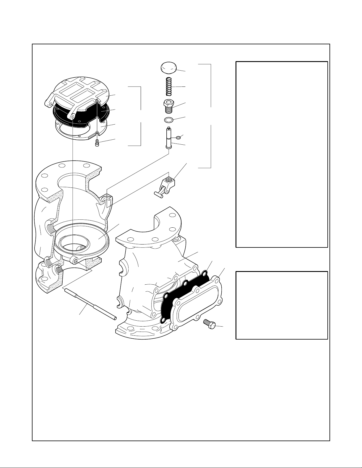
FIGURE 1A
DN100 MODEL DPV-1 DRY PIPE VALVE
— ASSEMBLY —
REPLACEMENT PARTS
NO. DESCRIPTION P/N
(a) Clapper Assembly
Includes Items:
6through10
(b) Repair Parts Kit
Includes Items:
4, 7, 14, 15, 18
(c) Reset Plunger Parts Kit
Includes Items:
11through 18 92-309-1-405........
92-309-2-403.........
92-309-1-404.......
Page 3

TFP1090
Page 3 of 22
NO. QTY.DESCRIPTION REF.
1 ValveBody 1 NR.......
2 Air and Water
3 Water Seal
O-Ring .......... NR1
4
NRSeat 1............
NRAir Seal O-Ring 1....
NO. QTY.DESCRIPTION REF.
5 3/8-16 UNC x 1"
Socket Head Cap
Handhole Cover Clapper
6
7 Handhole Cover
9
10
CLAPPER
ASSEMBLY
11
12
NR8Screw...........
NR See (a)
11
... ..........
See (d)Gasket 1..........
14
15
16
RESET
PLUNGER
17
PARTS
18, 21
19
20
NO. QTY.DESCRIPTION REF.
8 5/8-11UNC x 1"
Hex Head Cap
9
10
Clapper Facing
11
Clapper Facing
Retaining Plate
12
1/4-20 UNC x 1/2"
Socket Head Cap
13
Clapper Hinge
Pin
14
15
16 Reset Bushing See (c)1....
17 Reset Bushing
18
19 Reset Plunger See (c)1.....
20 Reset Latch
21 Dow Corning FS3452
.............
Reset Knob
Reset Spring
Reset Plunger
Subassembly 1 See (c)
Flourosilicone
....
......
.....
NR: Not Replaceable
CH: Common Hardware
CHScrew 6...........
See (a) or (b)
1
See (a)1....
See (a)9Screw...........
See (a)
1
See (c)
1
See (c)1.....
See (b) or (c)O-Ring 1...........
See (b) or (c)O-Ring 1...........
See (b) or (c)Grease, 1.5 g 1.....
13
REPLACEMENT PARTS
NO. DESCRIPTION P/N
(a) Clapper Assembly
Includes Items:
9through13
(b) Repair Parts Kit
2
4
5
3
Includes Items:
7, 10, 17, 18, 21
(c) Reset Plunger Parts Kit
Includes Items:
14 through 21 92-309-1-405........
1
7
6
8
92-309-2-603.........
92-309-1-604......
FIGURE 1B
DN150 MODEL DPV-1 DRY PIPE VALVE
— ASSEMBLY —
Page 4
Page4of22
Maximum
Water Supply
Pressure,
bar
1,4
System Air
Pressure
Range,
bar
0,7
TFP1090
0,60
0,50
0,40
4,1
5,5
6,9
8,3
10,0
11,4
12,8
14,1
1,0 - 1,6
1,4 - 1,9
1,7 - 2,3
2,1 - 2,6
2,4 - 3,0
2,8 - 3,3
3,1 - 3,7
3,4 - 4,0
15,5 3,8 - 4,3
16,0 4,1 - 4,6
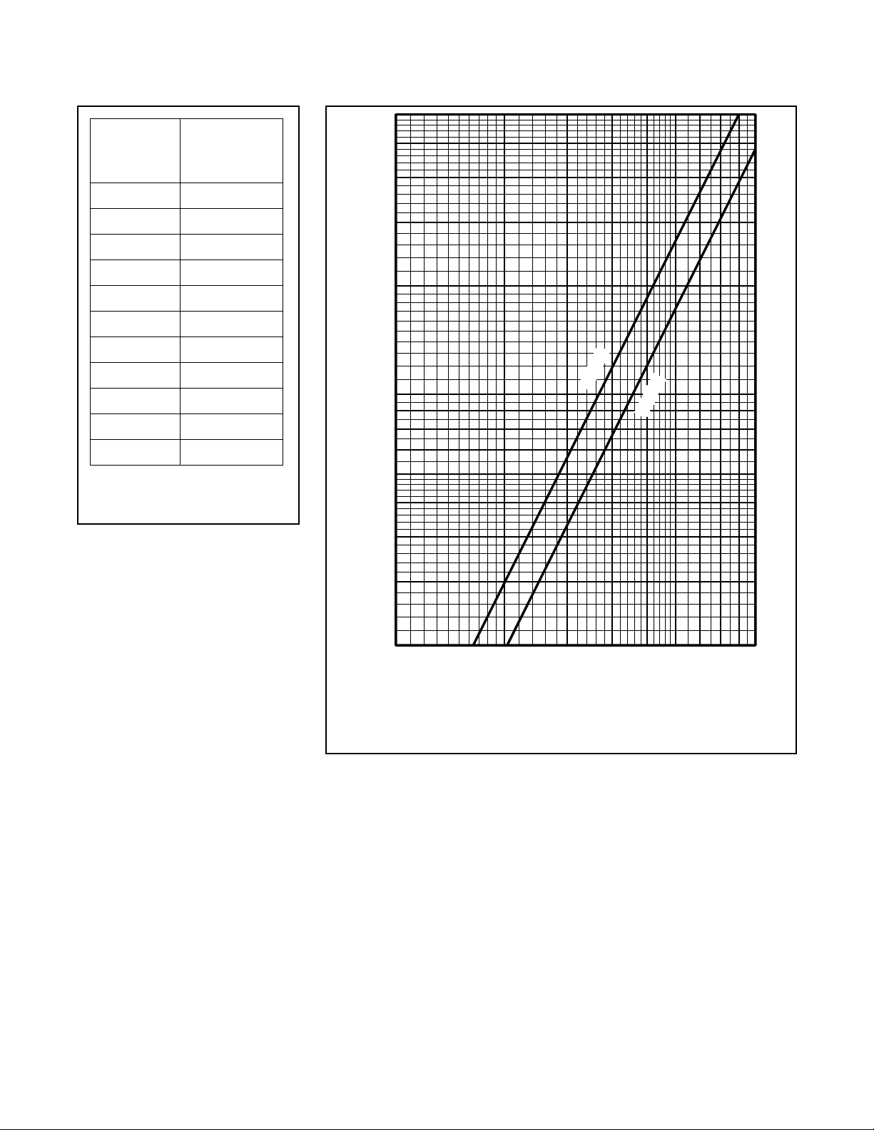
TABLE A
SYSTEM AIR PRESSURE
REQUIREMENTS
is a quick opening device that is intended to reduce the time for valve
operation foll owi ng the operation of
one or more automatic sprinklers. The
Model ACC-1 Accelera tor automatically adjusts to both small and slow
changes in system pressure, but trips
when there is a rapid and steady drop
in pressure (as in the case of a sprinkler operation). Upon tripping, the Accelerator transmits system air pressure to the intermediate chamber of
the Model DPV-1 Dry Pipe Valve. This
neutralizes the differential pressure
holding the Mode l DPV-1 Dry Pipe
Valve closed and permits it to open.
The Model ACC-1 Accelerator has a
unique, positive action, internal antiflood device a nd a ball float which
combine to prevent water and water
borne debris from entering the more
sensitive operating areas of the accelerator. The anti-flood device seals and
latches immediately upon operation of
the Model ACC-1 Accelerator without
waiting for a pressure build-up in the
intermediate chamber of the dry pipe
valve. The latching feature keeps the
anti-flood device sealed, even while
the system is being drained. The ball
float seals the pilot chamber inlet port
if there is an inadvertent trip of the dry
pipe valve, due for example, to an air
compressor failure combined with a
slow loss in system air pressuredue to
a leak.
0,30
0,20
0,10
0,09
0,08
0,07
NOMINAL PRESSURE DROP IN BAR
0,06
0,05
0,04
0,03
0,02
2000 3000 10000700050001000
FLOW RATE IN LITRES PER MINUTE (LPM)
FIGURE 2
DN100 and DN150 MODEL DPV-1 DRY PIPE VALVE
— NOMINAL PRESSURE LOSS VERSUS FLOW —
WARNING
TheModelDPV-1DryPipe Valves and
Model ACC-1 Dry Pipe Valve Accelerator described herein must be installed and maintained in compliance
with this document in addition to the
standards recognized by the Approval
agency, in addition to any other
authoritieshaving jurisdiction. Failure
to do so may impair the performance of these devices.
The owner is responsible for maintaining their fire protection system anddevices in proper operating condition.
The installing contractor or m anufacturer should be contacted with any
questions.
DN100
DN150
Page 5
TFP1090
00
50
Page 5 of 22
Technical
Data
Approvals:
The DN100 and DN150 Model DPV-1
Dry Pipe Valves with or without Model
ACC-1 Dry Pipe Valve Accelerator are
FM, LPCB, VDS, and CE Approved
with European Conformity Valve Trim
(Ref. Figures 8 thru 15).
DryPipeValve:
The DN100 and DN150, Model DPV-1
Dry Pipe Valves are for vertical installations (flow going up), and they are
rated for use at a maximum service
pressure of 16 bar. The nominal pressure loss versus flow is shown in Figure 2, and the valve take-out dimensions are shown in Figure 3.
Flanged connec tions are drilled per
ISO 2084 ( PN10/16) or ANSI B16.1
(Class 125). The grooved outlet connections, as applicable, are cut in accordance with standard groove specifications for steel pip e. They a re
suitable for use with grooved end pipe
couplings that are listed or approved
for fire protection system service.
Threaded port connections are per
ISO 7/1 to readily accept the trim arrangement detaile d in Fig ur es 8 -1 5 .
Components of the DN100 DPV-1
Valve are shown in Figure 1A, and
components of the DN150 DPV-1
Valve are shown in Figure 1B. The
Body and Handhole Cover are ductile
iron. The Handhole Cover Gasket is
neoprene, and the Clapper Facing is
EPDM. The Air/Water Seat Ring is
brass, the Clapper is c opper, and both
the Clapper Retaining Plate and Latch
arebronze. The Hinge Pin is aluminum
bronze, and the fasteners for the
Handhole Cover are carbon steel.
Valve Trim:
The Valve Trim is illustrated in Figures
8 and 15 (Ref. Table B). The Valve
Trim forms a part of the laboratory
approval of the DPV-1 Valve and is
necessary for the proper operation of
theDPV-1 Valve. Eachpackage of trim
includes the following items:
• Water Supply Pressure Gauge
• System Air Pressure Gauge
• Main Drain Valve
• Low Body Drain Valve
• Alarm Test Valve
• Automatic Drain Valve
• Provision For An Optional
Accelerator
Alarm Test Valve AcceleratorValve Size
DN100
üü ü138
üüü1510
üüü 1712
üüü1914
DN150 Three-Way Standard Yes No
üü ü 149
üüü1611
üü ü 1813
üüü 2015
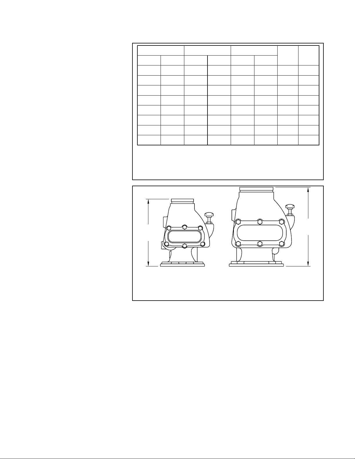
TABLE B
REFERENCE FOR CORRESPONDING
FIGURE NUMBER AND PAGE NUMBER
— EUROPEAN CONFORMITY VALVE TRIM —
346 mm
FxF, FxG,
or GxG
DN1
DN1
FIGURE 3
DN100 and DN150 MODEL DPV-1 DRY PIPE VALVE
— TAKE-OUT DIMENSIONS —
Air Supply:
TableA shows the system air pressure
requirementsas a function ofthewater
supply pressure. The air (or nitrogen)
pressurein the sprinkler system is recommended to be automatically maintained by using one of the following
pressure maintenance devices, as appropriate:
• Model AMD-1 Air Maintenance Device (pressure reducing type).
Quick Opening Device:
As an option, the Model DPV-1 Dry
Pipe Valve m ay be acquired with the
Model ACC-1 M echanical Dry Pipe
Valve Accelerator (Ref. Figure 4) The
ACC-1 is used to reduce the time to
valve actuation following the operation
of one or more automatic sprinklers.
Patents:
U.S.A. Patent No. 6 ,557,645 and
4,570,719.
• Model AMD-2 Air Maintenance Device (compressor control type).
• Model AMD-3 Nitroge n Maintenance Device (high pressure reducing type).
Figure
Number
Page
Number
406 mm
FxF, FxG,
or GxG
Page 6
Page6of22
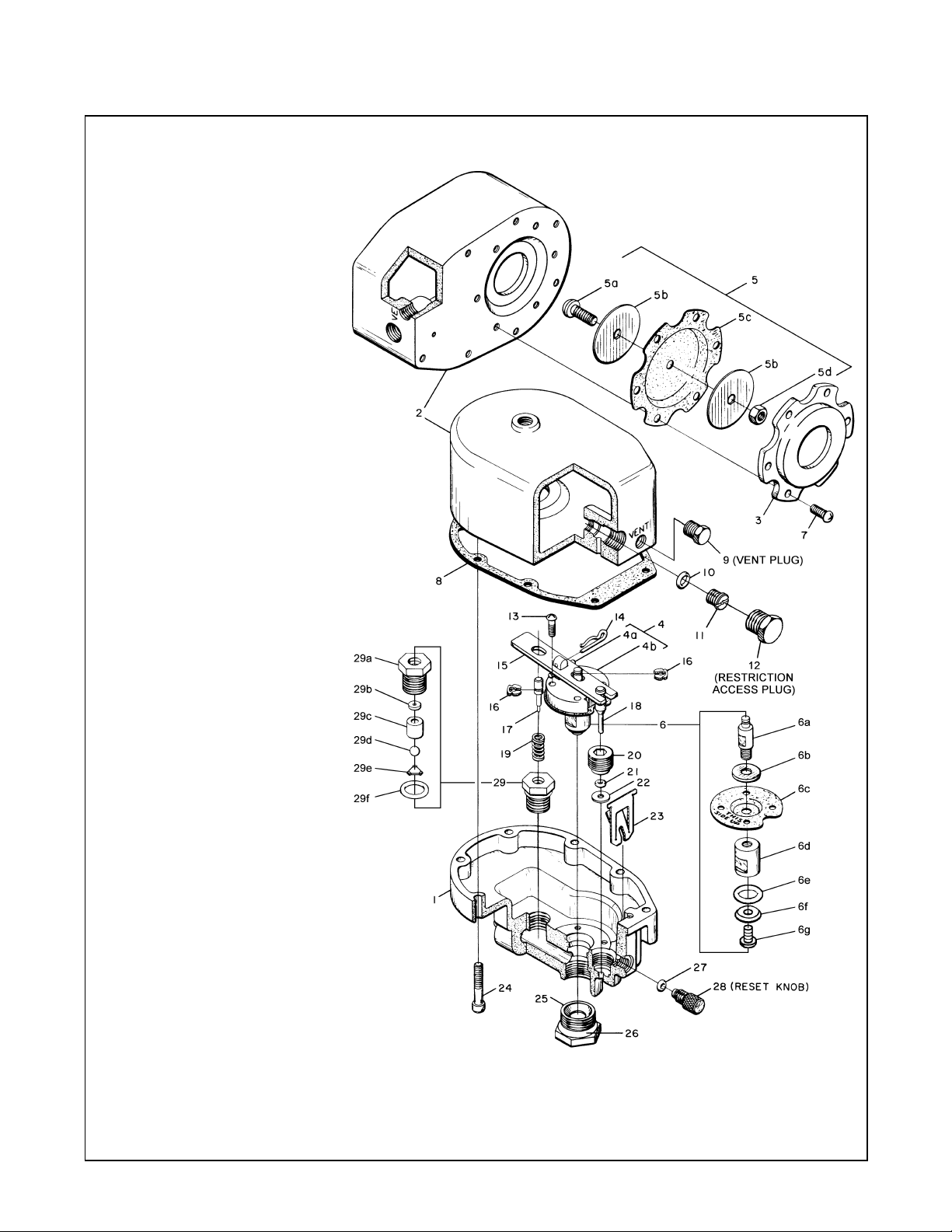
NO. DESCRIPTION QTY. P/N
1Base 1 NR
2 Cover 1 NR
3 Upper Diaphragm
Plate 1 See (c)
4 Pivot Plate
Assembly 1 See (b)
aSpirolPin 1
b Pivot Plate 1
5 Plunger 1 See (a)
a Pan Hd. Machine
Screw 1
b Upper Diaphragm
Retaining Ring 2
c Upper Diaphragm 1
dJamNut 1
6 Exhaust Valve 1 See (a)
a Upper Plug 1
b Washer 1
c Lower Diaphragm 1
d Lower Plug 1
e O-Ring* 1
f O-Ring Retainer 1
g Exhaust Valve Screw 1
7 Rd. Head Machine
Screw,
1/4"-20 UNC x 5/8" 6 See (c)
8 Cover Gasket 1 See (a)
9 Vent Plug 1 See (c )
10 O-Ring* 1 See(a)
11 Restriction 1 See (a)
12 Restriction Access
Plug 1 See (c)
13 Pan Hd. Machine
Screw,
No. 10-32 UNF x 5/8" 4 See (b)
14 Cotter Pin 1 See (b)
15 Lever 1 See (b)
16 Retaining Ring 1 See (b)
17 Anti-Flood Valve 1 See (b)
18 Relief Valve 1 See (b)
19 Spring 1 See (b)
20 Relief Valve Seat 1 See (b)
21 O-Ring* 1 See (b)
22 Seal Washer 1 See (b)
23 Latch 1 See ( a)
24 Fillerster Hd.
Machine Screw,
1/4"-20 UNC x 1-1/2" 8 See (c)
25 Plug Seat 1 See (c)
26 O-Ring* 1 See (c)
27 O-Ring* 1 See (a)
28 Reset Knob 1 See (c)
29 Anti-Flood Seat
Assembly
w/Ball Float 1 See (b)
a Insert 1
b Seal 1
c Guide 1
dBall 1
eClip 1
f O-Ring* 1
* Requires thin film of
FS3452 Fluorosilicone Grease
(a) Repair Parts Kit (a)
Includes Items 5, 6, 8,
10, 11, 23, 27 &
1.5 grams of FS3452 92-311- 1-116
(b) Replacement Parts
Kit (b) Includes Item s
4, 13-22, 29 &
1.5 grams of FS3452 92-311- 1-117
(c) Replacement Parts
Kit (c) Includes Item s
3, 7, 9, 12, 24-26, 28,
& 1.5 grams of FS3452 92-311-1-118
NR: Not Replaceable
TFP1090
FIGURE 4
MODEL ACC-1 ACCELERATOR ASSEMBLY
Page 7
TFP1090
O
Page 7 of 22
DN25
AIR SUPPLY
PORT
01
DN15
WATER
SUPPLY
PRESSURE
& ALARM
TEST PORT
02
CLAPPER
ASSEMBLY
LATCHED
OPEN
04
DN20
LOW BODY
DRAIN
PORT
AIR PRESSURE
TO SYSTEM
FROM
WATER SUPPLY
FIGURE 5A
SET POSITION
DRAIN FROM
SYSTEM
WATER SUPPLY
SHUT OFF
CLAPPER
ASSEMBLY
IN SET
POSITION
DN20 ALARM
PORT OPEN TO
ATMOSPHERE
03
WATER
SEAT
VALVE
WATERWAY
RESET
ASSEMBLY
CLAPPER
LATCH
DN50
MAIN DRAIN
05
PORT
CLAPPER LATCH
PIVOTS TOALLOW
CLAPPER ASSEMBLY
TO FULLY OPEN
CLAPPER
ASSEMBLY
FIGURE 5B
SET POSITION
INTERMEDIATE
CHAMBER
CLAPPER
ASSEMBLY
FULLY OPEN
AIR
SEAT
ALARM
03
PORT
INTERMEDIATE
CHAMBER
CLAPPER
LATCH
PIVOTS TO
UNLATCH
CLAPPER
ASSEMBLY
WATERFL
TO SYSTEM
WATER SUPPLY
W
FROM
FIGURE 5C
OPERATED POSITION
DRAIN FROM
SYSTEM
COMPLETE
WATER SUPPLY
SHUT OFF
ALARM PORT
WATERFLOW
TO ALARM
PUSH HERE
TO RESET
VALVE
RESET
KNOB
CLAPPER
ASSEMBLY
RESEATED
FIGURE 5D
DRAIN POSITION
FIGURE 5E
RESET POSITION
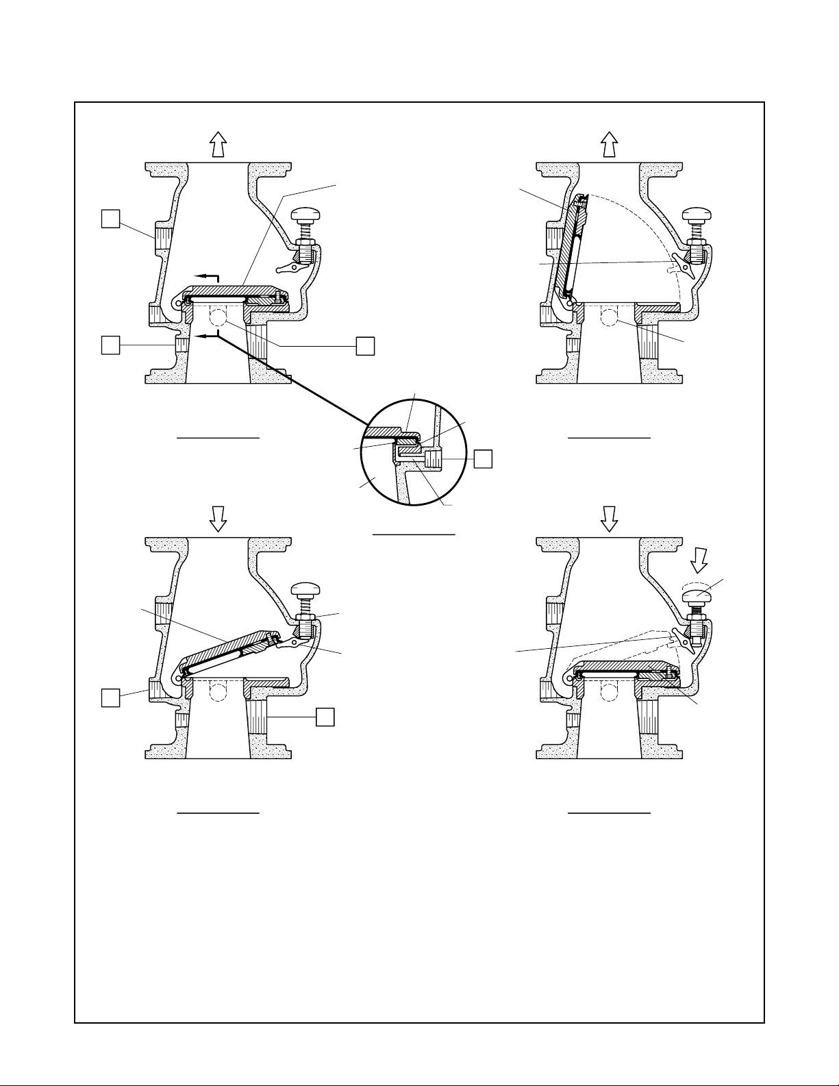
FIGURE 5
MODEL DPV-1 DRY PIPE VALVE (DN100 SHOWN)
— SET AND OPEN POSITIONS —
Page 8
Page8of22
TFP1090
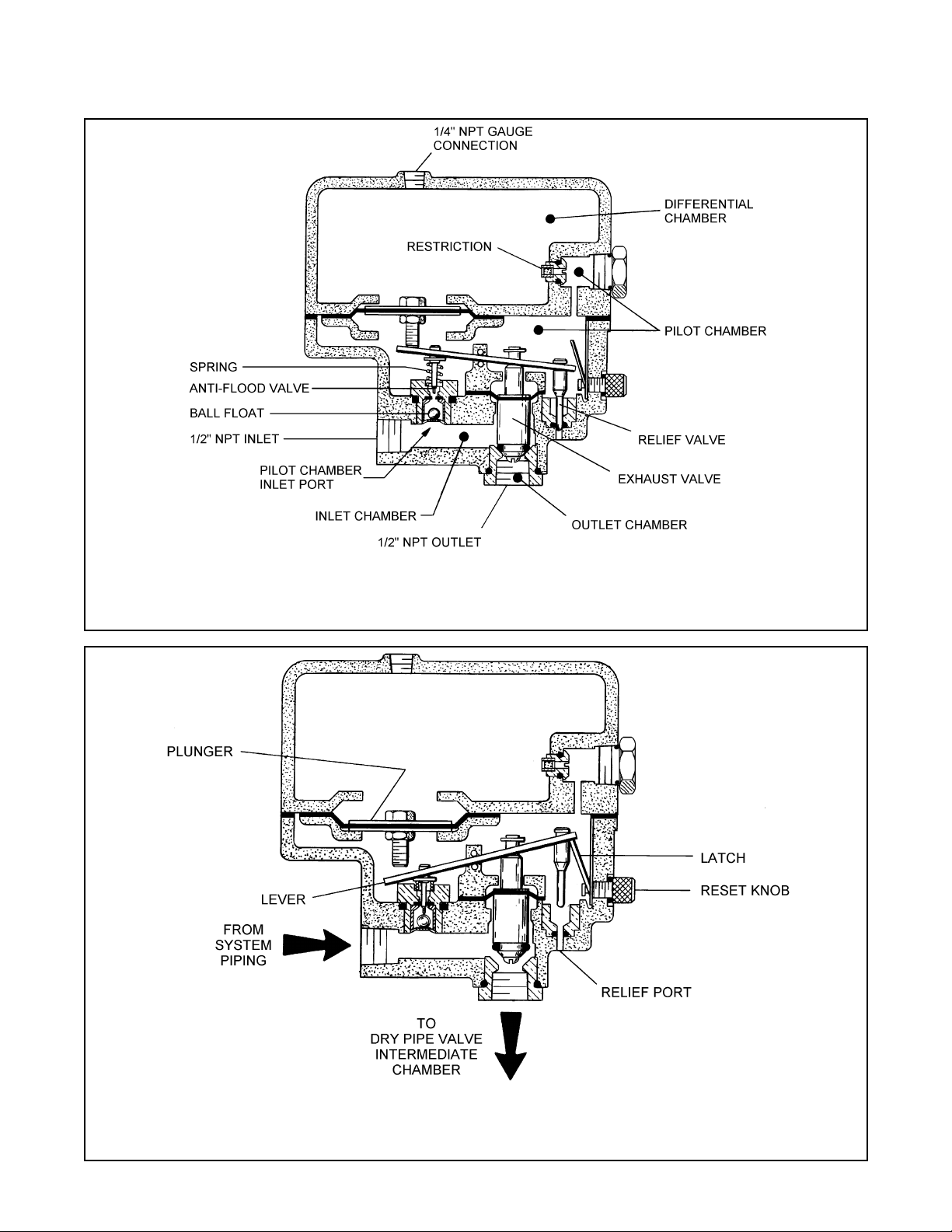
FIGURE 6
MODEL ACC-1 ACCELERATOR IN SET POSITION
FIGURE 7
MODEL ACC-1 ACCELERATOR IN TRIPPED POSITION
Page 9

TFP1090
Page 9 of 22
Operating
Principles
DRY PIPE VALVE
The Model DPV-1 Dry Pipe Valve is a
differential type valve that utilizes a
substantiallylowersystem(airor nitrogen) pressure than the supply (water)
pressure, to maintain the set position
shown in Figure 5A. The differential
nature of the DPV-1 is based on the
area difference between the air seat
and the water seat in combination with
the ratio of the radial difference from
the Hing e Pi n to the center of the
Water Seat and the Hinge Pin to the
center of the Air Seat. The difference
is such that the DPV-1 has a nominal
trip ratio of 5,5:1 (water to air).
Table A establishes the minimum required system air pressure th at includes a safety factor to help prevent
false operations that occur due to
water supply fluctuations.
The Intermediate Chamber of the
DPV-1isformedbytheareabetween
the Air Seat and Water Seat as shown
in Figure 5B. The Intermediate Chamber normally remains at atmospheric
pressure through the Alarm Port connection and the valve trim to the normally open Automatic Drain Valve
(Ref. Figures 8 thru 15). Having the
Intermediate Chamber, Figure 5B,
open to atmosphere is critical to the
DPV-1 Valve remaining set, otherwise
the full resulting pressure of the system air pressure on top of the Clapper
Assembly cannot be realized. For example, if the system air pressure is
1,7 bar and there was 1,0 bar pressure trapped in the Intermediate
Chamber, the r esulting pressure
across the top of the Clapper would
only be 0,7 bar. This pressure would
be insufficient to hold the Clapper Assembly closed against a water supply
pressure of 6,9 bar.
When one or more automatic sprinklers operate in response to a fire, air
pressure within the system piping is
relieved through the open sprinklers.
When the air pressure is sufficiently
reduced, the water pressure overcomes the differential holding the
Clapper Assembly closed and the
Clapper Assembly swings clear of the
water seat, as shown in Figure 5C,
This action permits water flow into the
system piping and subsequently to be
discharged from any open sprinklers.
Also,withtheClapperAssemblyopen,
the intermediate chamber is pressurizedand water flows through the alarm
port (Ref. Figure 5B) at the rear of the
DPV-1 Valve. As the flow through the
alarm port exceeds the drain capacity
of the Automatic Drain Valve, the
alarm line is pressurized to actuate
system water flow alarms.
After a valve actuation and upon subsequent closing of a system main control valve to stop water flow, the Clapper Assembly will latch open asshown
in Figure 5D. Latching open of the
DPV-1 will permit complete draining of
the system (including any loose scale)
through the main drai n po rt .
During the valve resetting procedure
and after the system is completely
drained, the external reset knob can
be easily depressed to externally unlatch the Clapper Assembly as shown
in Figure 5E. As such, the Clapper
Assembly is returned to its normal set
position to facilitate setting of the dry
pipe sprinkler system, without having
to remove the Handhole Cover.
ACCELERATOR
The Inlet Chamber of the Accelerator,
(Ref. Figure 6), is pressurized via its
connection to the system. The Pilot
Chamber is, in tur n, pressurized
throughits inlet port whichisformed by
the annular opening around the lower
tipofthe Anti-Flood Valve. Asthe Pilot
Chamber increases in pressure, the
Differential Chamber is pressurized
through the Restriction.
The Accelerator is in its set position
while it is being pressurized as well as
after the Inlet, Pilot Chamber and Differential Chamber pressures have
equalized. When in the Set position,
theOutlet Chamber is sealed offbythe
ExhaustValvewhichis held againstits
seat by a combination of the Spring
pushing up against the Lever and the
net downward force exerted by the
pressure in the Pilot Chamber.
Both small and slow changes in system pressure are accommodated b y
flow through the Restriction. When,
however, there is a rapid and steady
drop in system (i.e., Inlet and Pilot
Chamber) pressure, the pressure in
the Differential Chamber reduces at a
substantially lower rate. This condition
creates a net downward force on the
Plunger which rotates the Lever. As
theLeveris rotated (Ref. Figure7),the
Relief Valve is raised out of the Relief
Port and the Anti-Flood Valve is depressed downward into the Pilot
Chamber Inlet Port, venting the Pilot
Chamber.
The system pr essure in the Inlet
Chamber then forces (raises) the Exhaust Valve off its seat. Thiscontinues
the rotation of the Lever into the
tripped (latched) position (Ref. Figure
7). As the Exhaust Valve is raised off
its seat, system pressure is transmit-
ted to the intermediate chamber of the
dry pipe valve which neutralizes the
differential pressure holding the valve
closed.
Water and any water borne debris
such as silt is prevented from entering
the Pilot Chamber by virtue of the AntiFlood Valve having sealed off its inlet
port.
After the accelerator/dry pipe valve
has tripped and the sprinkler system
has been drained, the piping from the
systemto theAccelerator must also be
drained and the Accelerator reset/inspected according to the instructions
given in the Valve Setting Procedure
section.
The rate-of-flow through the Restriction has been set such that the M odel
ACC-1 Accelerator provides the maximum practical sensitivity to a loss in
system pressure due to a sprinkler operation while sti ll being capable of
automatically compensating for normal variations in system pressure
such as are caused by environmental
temperaturechanges. A test for verifying that the rate-of-flow through the
Restriction is within the range for optimumA ccelerator performanceisgiven
in the Valve Setting Procedure section.
Page 10

Page 10 of 22
TFP1090
Installation
NOTES
Proper operation of the Model DPV-1
Dry Pipe Valve depends upon its trim
being installed in accordance with Figures 8 thru 15, as applicable. Alteration of the trim may prevent the DPV-1
Valve from functioning properly, as
well as void approvals and the manufacturer’s warranties.
Failure to latch open the Clapper Assembly prior to a system hydrostatic
test may result in damage to the Clapper Assembly.
The DPV-1 Valve must be installed in
a readily visible and accessible location.
The DPV-1 Valve and associated trim
mustbemaintainedataminimumtemperature of 4°C.
Heat tracing of the DPV-1 V alv e or its
associated trim is not permitted. Heat
tracing can result in the formation of
hardenedmineraldepositsthatarecapable of preventing proper operation.
The Model DPV-1 Dry Pipe Valve is to
be installed in accordance with the following criteria:
Step 1. When trimming valves in the
field (i.e., other than valves provided
with factory assembled trim), all nipples, fittings, and devices must be
clean and free of scale and burrs before installation. Use pipe thread
sealantsparinglyon male pipe threads
only.
Step 2. The DPV-1 Valve must be
trimmed in accordance with Figures 8
thru 15.
Step 3. Care must be taken to make
sure that check valves, strainers,
globevalves, etc. are installed with the
flow arrows in the proper direction.
Step 4. Sui table provision must be
made for disposal of drain water.
Drainage water must be directed such
that it will not cause accidental damage to property or danger to persons.
Step 5. Installation of an Air Maintenance Device, as described in the
Technical Data Section, is recommended.
Step 6. An Inspector’s Test Connection must be provided on the system
pipingat the mostremotelocation from
the Model DPV-1 Valve.
Step 7. Conduitand electrical connections are to be made in accordance
with the requirements of the authority
having jurisdiction.
Step 8. Before a system hydrostatic
test is performed in accordance with
the standards recognized by the Approval agency, in addition to any other
authorities having jurisdiction, the
Clapper Assembly is to be manually
latched open (Ref. Fig. 4D); the Automatic Drain Valve (Ref. Figures 8 thru
15) is to be temporarily plugged, and
the Handhole Cover Bolts are to be
tightened using a cross-draw sequence.
Valve Setting
Procedure
Steps 1 through 12 are to be performed when initially settingthe Model
DPV-1 Dry Pipe Valve; after an operationaltestofthefireprotectionsystem;
or, after system operation due to a fire.
Determine which of Figures 8 through
15 is applicable for your given riser
arrangement,and then proceed as follows:
Step 1. Close the Main Control Valve,
and close the Air Supply Control
Valve.
IftheDPV-1isequippedwitha
Dry Pipe Valve Accelerator, close the
Accelerator Control Valve.
Step 2. Open the Main Drain V al v e
and all auxiliary drains in the system.
Close the auxiliary drain valves after
water ceases to discharge. Leave the
Main Drain V alve open.
Step 3. As applicable, place the
Three-way Alarm Control Valve in the
open position.
Step 4. Verify thatthe A utomatic Drain
Valve has stopped draining to determinetheDPV-1Valveiscompletely
drained.
Step 5. As necessary, replace all
sprinklers that have operated. Replacement sprinklers must be of the
same type and temperature rating as
those which have operated.
In order to prevent the possibility of a
subsequent operation of an overheated solder type sprinkler, any solder type sprinklers which were possibly exposed to a temperature greater
than the ir maximum rated ambient
must be replaced.
Step 6. Push down on the Reset Knob
(Fig. 5E) to allow the Clapper Assembly to reseat.
Step 7. Pressurize the system with air
(or nitrogen) to 0,7 bar, and then individually open all auxiliary drain valves
NOTE
in the system piping to drain any remaining water in trapped sections.
Close each drain valve as soon as
water ceases to discharge. Also partially open the Low Body Drain V alve
in the valve trim to assure thatthe riser
is completely drained. Close the Low
Body Drain Valve as soon as water
ceases to discharge.
Step 8. Refer to Table A and then
restore the system to the normal system air pressure as necessary to hold
the DPV-1 Valve closed.
Step 9. Verify that there is not any air
discharging from the Automatic Drain
Valve.
The absence of air discharging from
theAutomaticDrainValveis an indication of a properl y set air seat wit h in the
DPV-1Valve. If air is discharging,refer
to the Care and Maintenance section
under Automatic Drain Valve Inspection to determine/correct the cause of
the leakage problem.
Step 10. If the DPV-1 is equipped with
aDry Pipe Valve Accelerator, reset the
Dry Pipe Valve Accelerator in accordance with Steps 10A thru 10H. Otherwise, proceed to Step 11.
Step 10A. While holding the plunger
of the A utomatic Drain Valve depressed, open the Accelerator Control Valve one-quarter turn and allow
the water in the Accelerator piping to
blowout.Afterwaterspray stops discharging, close the Accelerator Control Valve and then release the
plunger.
Step 10B. Slowly remove the Vent
Plug located in the frontof the Accelerator Cover and bleedoff any residual air pressure in the Differential
Chamber.
Step 10C. Unscrew (counter-clockwise rotation) the knurled Reset
Knob at the front of the Accelerator
until it resists further turning. A click,
whichis thesound of the Lever snapping back into the Set Position, may
be heard. Scre w t he Res et Knob
back in until it is finger tight.
NOTE
Do not wrenchon the reset Knob, since
damagemayresult. TheResetKnobwill
turn with finger torque only.
Step 10D. Replace the Vent Plug.
Step 10E. Verify that the system air
pressure has returned to normal.
Step 10F. Using a watch, note the
time for the pressure in the Differential Chamber of the Accelerator to
increase to 0,7 bar after the Accelerator Control Valve is opened. The
Page 11

TFP1090
Pressure, bar Minimum, sec. Maximum, sec.
1,4 24 160
1,7 18 116
2,1 15 92
2,8 10 60
3,5 8 48
4,1 6 36
TABLE C
DIFFERENTIAL CHAMBER FILL TIMES TO 0,7 BAR
time should be within the range of
values indicated in Table C for optimum performance of the Accelerator.
NOTE
If the time to pressurize the Differential
Chamber to 0,7 bar is not within the
range of values given in the Table C,
then the Accelerator Control Valve
shouldbe closed and the correctiveprocedure described in the Careand Maintenance Section followed.
Step 10G. When the air pressure in
the Differential Chamber of the Accelerator is equal to that in the system, then the Accelerator is set and
ready for service.
Step 10H. Close the Accelerator
Control Valve and then slowly open
theLow Body Drain Valve in the trim,
to bleed off any excess water
trapped above the dry pipe valve
clapper.Reclose the LowBodyDrain
Valve, return system pressure to its
normal value, and then re-open the
Accelerator Control Valve.
Step 11. Partially open the Main Control Valve. Slowly close the Main Drain
Valve as soon as water discharges
from the drain connection.
Verify that there is not any water discharging from the Automatic Drain
Valve.
The absence of water discharging
from the Automatic Drain Valve is an
indication of a properly set water seat
within the DPV-1 Valve. If water is discharging, refer to the Care and Maintenance section under the Automatic
Drain V alve In spection to dete rmine/correct the cause of the leakage
problem.
If there are no leaks, the DPV-1 Valve
isready tobeplacedinservice andthe
Main Control Valve must then be fully
opened.
NOTE
After setting a fire protection system,
notify the proper authorities and advise those responsible for monitoring
proprietary and/or central station
alarms.
Step 12. Once a week after a valve is
reset following an operational test or
system operation, the Low Body Drain
Valve (and any low point drain valves)
should be partially opened (and then
subsequently closed) to relieve drainback water. Continue this procedure
until drain-back water is no longer present.
Care and
Maintenance
The following procedures and inspections should be performed as indicated, in addition to any specific requirements of any authority having
jurisdiction. Impairments must be immediately corrected.
The owner is responsible for the inspection, testing, and maintenance of
their fire protection system and devices in c om plia nce with this document, as well as with the applicable
standardsof any authorityhavingjurisdiction. The installing contractor or
product manufacturer should be contacted relative to any questions.
It is recommended that automatic
sprinkler systems be inspected,
tested, and maintained by a qualified
Inspection Service.
NOTES
The operational test procedure and
waterflow pressure alarm test procedure will result in operation of the associated alarms. Consequently, notification must first be given to the owner
and the fire department, central station,or other signal stationtowhichthe
alarms are connected.
Before closing a fire protection system
main control valve for maintenance
work on the fire protection system that
itcontrols, permission to shutdownthe
affected fire protection systems must
first be obtained from the proper
authorities and all personnel who may
be affected by this decision must be
notified.
Page 11 of 22
Annual Operation Test Procedure
Proper operation of the DPV-1 Valve
(i.e., opening of the DPV-1 Valve during a fire condition) should be verified
at least once a year as follows:
Step 1. If water must be prevented
from flowing beyond the riser, perform
the following steps.
• Close the Main Control Valve.
• Open the Main Drain Valve.
• Open the Main Control Valve one
turn beyond the position at which
water just begins to flow from the
Main Drain Valve.
• Close the Main Drain Valve.
Step 2. Open the system’s Inspector’s
Test Connection.
Step 3. Verify that the DPV-1 Valve
has operated, as indicated by the flow
of water into the system and that all
waterflow alarms operate properly.
Step 4. Close the system’s Main Control Valve.
Step 5. Reset the DPV-1 Valve in accordancewith the ValveSetting Procedure.
NOTE
It is recommended that the inside of
the valve be inspected at this time and
prior to resetting theDPV-1 Valve. Refer to the Self Closing Drain Valve Inspection sub-section Steps 2 through
5 for instructions with regard to the
inspection of the Clapper Facing.
Periodic Waterflow Alarm Test
Procedure
Testing of the system waterflow
alarms should be performed periodically based on the requirements of
the authority having jurisdiction. To
test the waterfl ow alarm, place the
Three-wayAlarmTestValveinthe
“Test” position or open the Standard
AlarmTestValve,asapplicable,which
will allow a flow of water to the Waterflow Pressure Alarm Switch and/or
Water Motor Alarm. Upon satisfactory
completion of the test, place the
Three-wayAlarmTestValveinthe
“Open” position or close the Standard
Alarm Test Valve, as applicable.
Water Pressure Inspection
The Water Pressure Gauge is to be
inspectedperiodically based on the requirements of the authority having jurisdictionto ensure that normal system
water pressure is being maintained.
Air Pressure Inspection
The Air Pressure Gauge is to be inspected periodically based on the requirements of the authority having ju-
Page 12

Page 12 of 22
TFP1090
risdictionto ensure that normal system
air pressure is being maintained.
Automatic Drain Valve Inspection
The Automatic Drain Valve should be
inspectedperiodically based on the requirements of the authority having jurisdiction by depressing the plunger
and checking to ensure that the Automatic Drain Valve is not discharging
water and/or air. A discharge of water
and/or air is an indication that the air
and/or water seats are leaking, which
could subsequently cause a false operation should the intermediate chamberbecomeinadvertentlypressurized.
If leakage is present, take the DPV-1
Valve out of service (i.e., close the
main control valve, open the main
drainvalve, close the air supplycontrol
valve, remove the Dry Pipe Valve Accelerator from service, as applicable,
by closing the Accelerator Control
Valve, and open the Inspector’s Test
Connection to relieve the system air
pressure to 0 psig as indicated on the
SystemAirPressureGauge), and then
after removing the Handhole Cover,
perform the followin g st eps :
Step 1. Make sure that the Seat Ring
is clean and free of any n icks orsignificant scratches.
Step 2. Remove the Clapper Assembly from the valve by first pulling out
the Hinge Pin.
Step 3. Disassemble the Clapper Facing Ret a ine r from the Cl app er so that
the Clapper Facing can be removed
and inspected. Make sure that the
ClapperFacingdoes not show signs of
compression set, damage, etc. Replacethe Clapper Facing if thereisany
signs of wear.
Step 4. Clean the Clapper Facing,
Clapper,and ClapperFacingRetainer,
and then reassemble the Clapper Assembly.
Step 5. Reinstall the Clapper Assembly with its Hinge Pinand thenreinstall
the Handhole Cover.
Accelerator Inspection Procedur e
Itis recommended that theAccelerator
be inspected periodically based onthe
requirements of the authority having
jurisdiction to determine proper operation of the Accelerator without having
to trip the dry pipe valve. This procedure mus t also be used whenever
flooding the system would expose the
water to freezing conditions.
trouble shooting of the Model ACC-1
Dry Pipe Valve Accelerator.
Step 1. Verify that the Reset Knob is
screwed in.
Step 2. Close the system’s main control valve and open the main drain
valve to relieve the supply pressure to
the dry pipe valve.
Step 3. Verify that the Accelerator
Control Valve is open.
Step 4. Open the Inspector’s Test
Connection. Verify that the time to Acceleratortrip is essentially thesameas
in previous tests. A momentary burst
of air from the Automatic Drain Valve
indicates that the Accelerator has
tripped.
NOTE
As the system pressure is decreasing,
check for any sign of water being discharged from the Accelerator Relief
Port.
Step 5. Depress the plunger of the
Automatic Drain Valv e. A steady
stream of exhausting air indicates that
theAcceleratorhas properly latched in
the Tripped position.
Step 6. Close the Accelerator Control
Valve and the Inspector’s Test Connection.
Step 9 . After the system automatically
restores itself to its normal air pressure, reset the Accelerator and Dry
Pipe Valve in accordance with the
Valve Setting Procedure Steps 10 and
11.
Limited
Warranty
Products manufactured by Tyco Fire &
Building Products (TFBP) are warranted solely to the original Buyer for
ten (10) years against defects in material and workmanship when paid for
and properly installed and maintained
under normal use and service. This
warranty will expire ten (10) years
from date of shipment by TFBP. No
warranty is given for products or components manufactured by companies
not affiliated by ownership with TFBP
or for products and components which
havebeen subject to misuse, improper
installation, corrosion, or which have
not been installed, maintained, modified or repaired in accordance with the
standards recognized by the Approval
agency, as well as the standards of
any other Authorities Having Jurisdiction. Materials found by TFBP to be
defective shall be either repaired or
replaced, at TFBP’s sole option.TFBP
neither assumes, nor authorizes any
person to assume for it, any other obligation in connection with the sale of
products or parts of products. TFBP
shall not be responsible for sprinkler
system design errors or inaccurate or
incomplete information supplied by
Buyer or Buyer’s representatives.
In no event shall TFBP be liable, in
contract, tort, strict liability or under
any other legal theory, for incidental,
indirect,special or consequential damages, including but not limited to labor
charges, regardless of whether TFBP
was informed about the possibility of
such damages, and in no event shall
TFBP’s liability exceed an amount
equal to the sales price.
Theforegoingwarrantyismadeinlieu
of any and all other warranties, express or implied, including warranties
ofmerchantability and fitnessfor a particular purpose.
This limited warranty sets forth the exclusive remedy for claims based on
failure of or defect in products, materials or components, whether the claim
is made in contract, tort, strict liability
or any other legal theory.
This warranty will apply to the full extent permitted by law. The invalidity,in
whole or part, of any portion of this
warranty will not affect the remainder.
Refer to Tec hnical Data Sheet
NOTE
TFP1112 for guidance with regard to
Page 13

TFP1090
Page 13 of 22
NO.
DESCRIPTION
025500013; Water gauge; 1/4" npt; 300 psi
1
1610000210; Ball valve; brass; full bore; 1/2" BSP; PN30;
2
kv=16.3; pr
1610000270; Ball valve; brass; full bore; 3/4" BSP; PN30;
3
kv=29.5; pr
1610000600; Ball valve; brass; full bore; 2" BSP; PN25;
4
kv=265; ur
2162156; Automatic drain valve; 1/2";
5
oper: k=25 & non oper: k=5
260; Alarm pressure switch
6
262; Low pressure switch
7
305105; Check valve brass thread;
8
DN15 male x DN15 fem.; nickel plated
9
406012; Elbow 3 mm x m5
Dry pipe valve; DPV-1; ductile iron; 4"
10
59304FO; Ball valve; size 1/2"; full bore; PN40;
11
venthole threaded
923431012; Air pressure gauge;12
300 psi; 1/4" npt
13
A130RIID2; malleable fitt.; reducing tee; BSP thread 2" x 2"
14
A280I2; malleable fitting; nipple male; BSP thread;
size 2"; galvanized
15
A291E2; malleable fitting; plug male; BSP thread;
size 3/4"; galvanized
16
AP100E4; pipe nipple; stainless steel 316; size 3/4";
length 100 mm
17
AP120I2; pipe nipple; steel; size 2"; length 120 mm;
galvanized
18
AP180D4; pipe nipple; stainless steel 316; size 1/2";
length 180 mm
19
AP80D4; pipe nipple; stainless steel 316; size 1/2";
length 80 mm
..........................................
..........................................
...........................................
.............................
.............................
...............................
..............................
.....................................
......................................
....................................
...................................
.......................................
..........................................
.......................................
........................................
36
.....................
.....................
28
32
19
21
24
6
15
30
.................
....
7
24
20
2
33
24
31
11
22
33
8
24
25
32
16
20
3
5
QTY.
120
1
1
1
1
1
1
1
3
1
3
1
1
1
1
1
1
1
1
9
35
9
35
28
25
18
DESCRIPTION
NO.
ATDDMN;Adapter fitting; brass;
thread DN15 x DN15 male; nickel pl.
ATDFCON;Adapter fitting; brass;
21
thread DN15 fem. x compr.15 mm; n.
ETDDMN; Adapter elbow; brass;
22
thread DN15 male x DN15 male; nickel pl.
ETDMCON; Adapter elbow; brass;
23
thread DN15 male x compr.15 mm; nickel pl.
ETDMDFN; Adapter elbow; brass;
24
thread DN15 male x DN15fem.; nickel pl.
ETEMEFN; Adapter elbow; brass;
25
thread DN20 male x DN20 fem.; nickel pl.
K00128; Alarm test/shut off valve; PN40; 1/2"; BSP; 3 way
26
MANIF3WAY; Manifold; threaded; nickel plated brass;
27
DN25 x DN15
PTDN; Plug; brass; thread DN15 male; nickel plated
28
RTDMBFN; Adapter reduce; brass;
29
thread DN15 male x DN8 fem.; nickel pl.
30
RTDMEFN; Adapter reduce; brass;
thread DN15 male x DN20 fem.; n.
RTEMDFN; Adapter reduce; brass;
31
thread DN20 male x DN15 fem.; n.
32
TTDDDFN; adapter tee; brass;
thread DN15 fem x DN15 fem x DN15 fem; nickel pl.
33
TTDDMDFN; adapter tee; brass;
thread DN15 male x DN15 male x DN15 fem; n.
34
UTFFMN; Adapter union; brass;
thread DN25 x DN25 male; nickel plated
35
WS00000004; Pressure relief hose;
3 x 6 length 1.2 m; transparent
36
WS00000082; Nickel pl.c opp. tube 15 x 1 mm
type B for DPV-1 DN100
12
29
11
34
27
20
......................
.....................
..................
................
...................
..................
........................................
...................2
........................
........................
.............
...................
...........................
................................
1
9
35
20
17
10
29
11
13
14
4
.....
..........
..........
QTY.
4
1
1
1
4
2
1
1
2
1
1
2
2
1
3
1
23
26
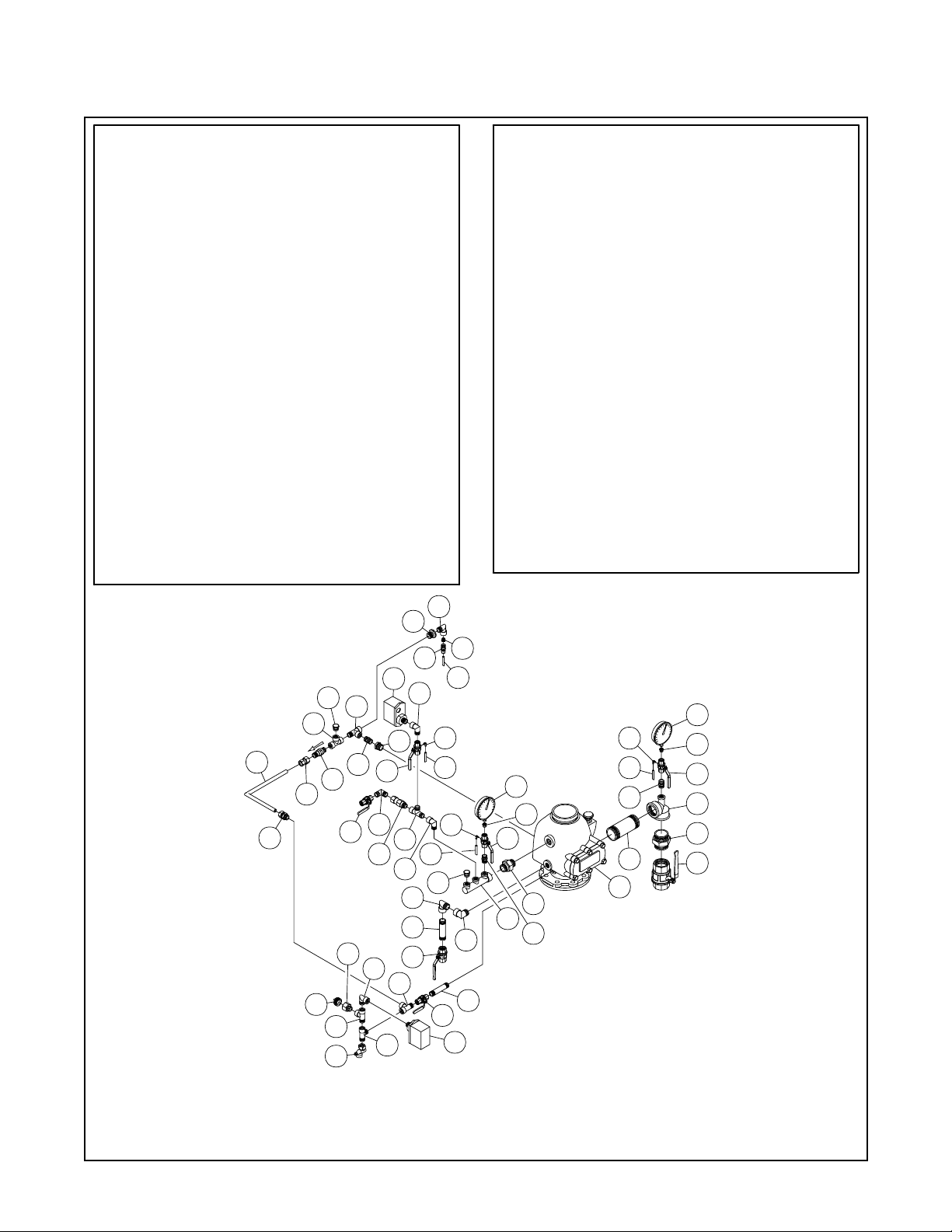
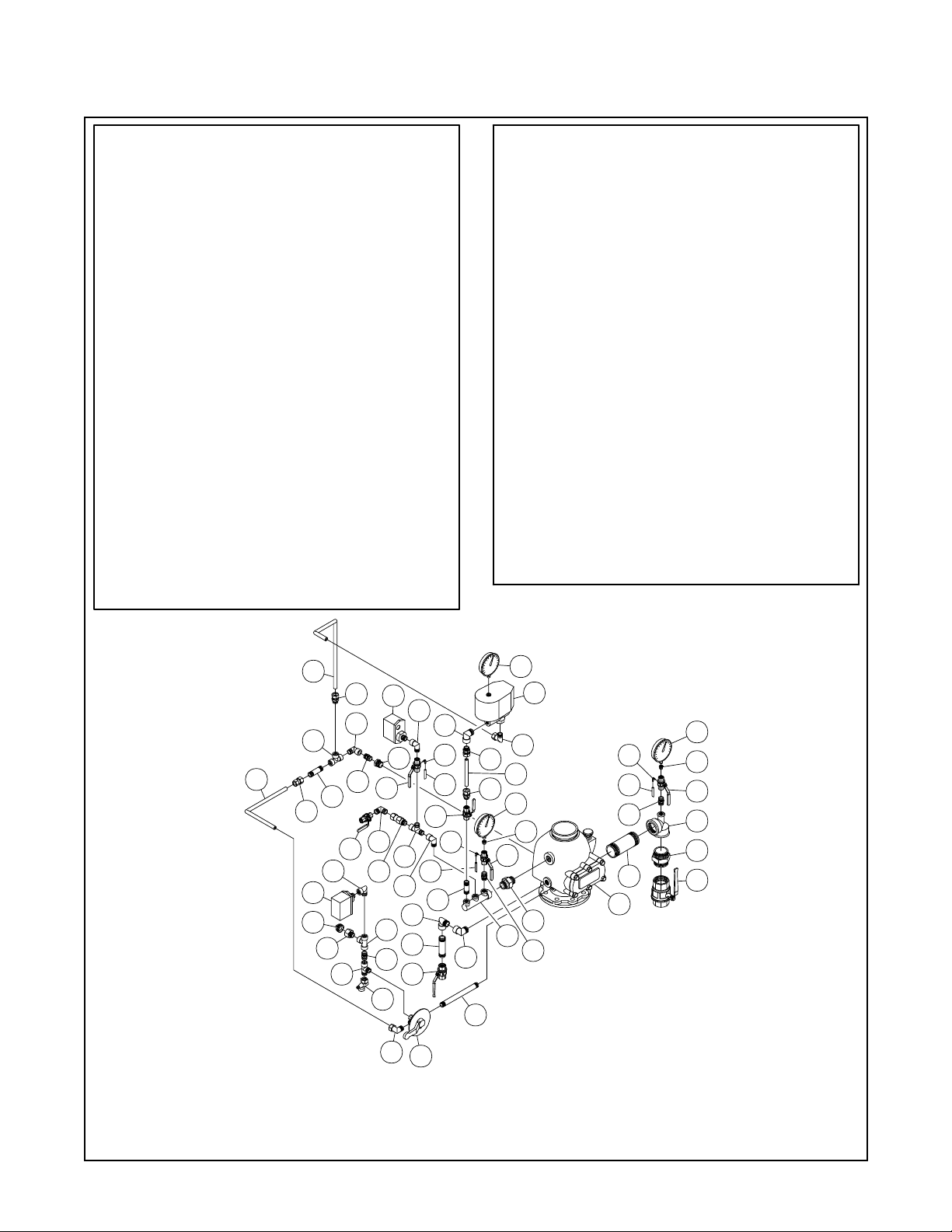
FIGURE 8
EUROPEAN CONFORMITY
DPV-1 DRY PIPE VALVE TRIM with THREE-WAY ALARM TEST VALVE
without ACC-1 ACCELERATOR
— DN100 —
Page 14

Page 14 of 22
NO.
DESCRIPTION
025500013; Water gauge; 1/4" npt; 300 psi
1
1610000210; Ball valve; brass; full bore; 1/2" BSP; PN30;
2
kv=16.3; pr
1610000270; Ball valve; brass; full bore; 3/4" BSP; PN30;
3
kv=29.5; pr
1610000600; Ball valve; brass; full bore; 2" BSP; PN25;
4
kv=265; ur
2162156; Automatic drain valve; 1/2";
5
oper: k=25 & non oper: k=5
6
260; Alarm pressure switch
262; Low pressure switch
7
305105; Check valve brass thread;
8
DN15 male x DN15 fem.; nickel plated
9
406012; Elbow 3 mm x m5
Dry pipe valve; DPV-1; ductile iron; 6"
10
59304FO; Ball valve; size 1/2"; full bore; PN40;
11
venthole threaded
923431012; Air pressure gauge;
12
300 psi; 1/4" npt
A130RIID2; malleable fitt.; reducing tee; BSP thread 2" x 2"
13
14
A280I2; malleable fitting; nipple male; BSP thread;
size 2"; galvanized
A291E2; malleable fitting; plug male; BSP thread;
15
size 3/4"; galvanized
16 AP100D4; pipe nipple; stainless steel 316; size 1/2";
length 100 mm
AP100I2; pipe nipple; steel; size 2"; length 100 mm;
17
galvanized
AP120E4; pipe nipple; stainless steel 316; size 3/4";
18
length 120 mm
AP180D4; pipe nipple; stainless steel 316; size 1/2";
19
length 180 mm
AP60D4; pipe nipple; stainless steel 316; size 1/2";20
length 60 mm
..........................................
..........................................
...........................................
.............................
.............................
...............................
..............................
.....................................
......................................
....................................
...................................
.......................................
...........................................
.......................................
.......................................
........................................
.....................
.....................
.................
....
QTY.
1
1
1
1
1
1
1
1
3
1
3
1
1
1
1
1
1
1
1
1
DESCRIPTION
NO.
ATDDMN;Adapter fitting; brass;
21
thread DN15 x DN15 male; nickel pl.
ATDFCON;Adapter fitting; brass;
22
thread DN15 fem. x compr.15 mm; n.
ETDDMN; Adapter elbow; brass;
23
thread DN15 male x DN15 male; nickel pl.
ETDMCON; Adapter elbow; brass;
24
thread DN15 male x compr.15 mm; nickel pl.
ETDMDFN; Adapter elbow; brass;
25
thread DN15 male x DN15fem.; nickel pl.
ETEEMN; Adapter elbow; brass;
26
thread DN20 male x DN20 male; nickel pl.
ETEMEFN; Adapter elbow; brass;
27
thread DN20 male x DN20 fem.; nickel pl.
MANIF3WAY; Manifold; threaded; nickel plated brass;
28
DN25 x DN15
29
PTDN; Plug; brass; thread DN15 male; nickel plated
RTDMBFN; Adapter reduce; brass;
30
thread DN15 male x DN8 fem.; nickel pl.
31
RTDMEFN; Adapter reduce; brass;
thread DN15 male x DN20 fem.; n.
32
TTDDDFN; adaptertee; brass;
thread DN15 fem x DN15 fem x DN15 fem; nickel pl.
33
TTDDMDFN; adaptertee; brass;
thread DN15 male x DN15 male x DN15 fem; n.
34
UTFFMN; Adapter union; brass;
thread DN25 x DN25 male; nickel plated
35
WS00000004; Pressure relief hose;
3 x 6 length 1.2 m; transparent
36
WS00000088; Nickel pl. copp. tube 15 x 1 mm
type D for DPV-1 DN150
37
WS00000095; Alarm test/shut off valve; PN40; 1/2";
BSP; 3 way
........................................
........................
...........................
................................
..........................................
TFP1090
......................
.....................
..................
................
...................
..................
..................
..........
...................
..........
.............2
...................
QTY.
2
1
1
1
4
1
1
1
2
2
2
2
1
3
1
1
7
11
35
23
2
33
835
25
25
13
14
6
15
36
16
25
9
12
30
9
29
28
17
9
20
4
32
29
11
21
1
30
35
11
25
22
31
18
26
27
34
3
31
21
10
32
33
5
24
37
19
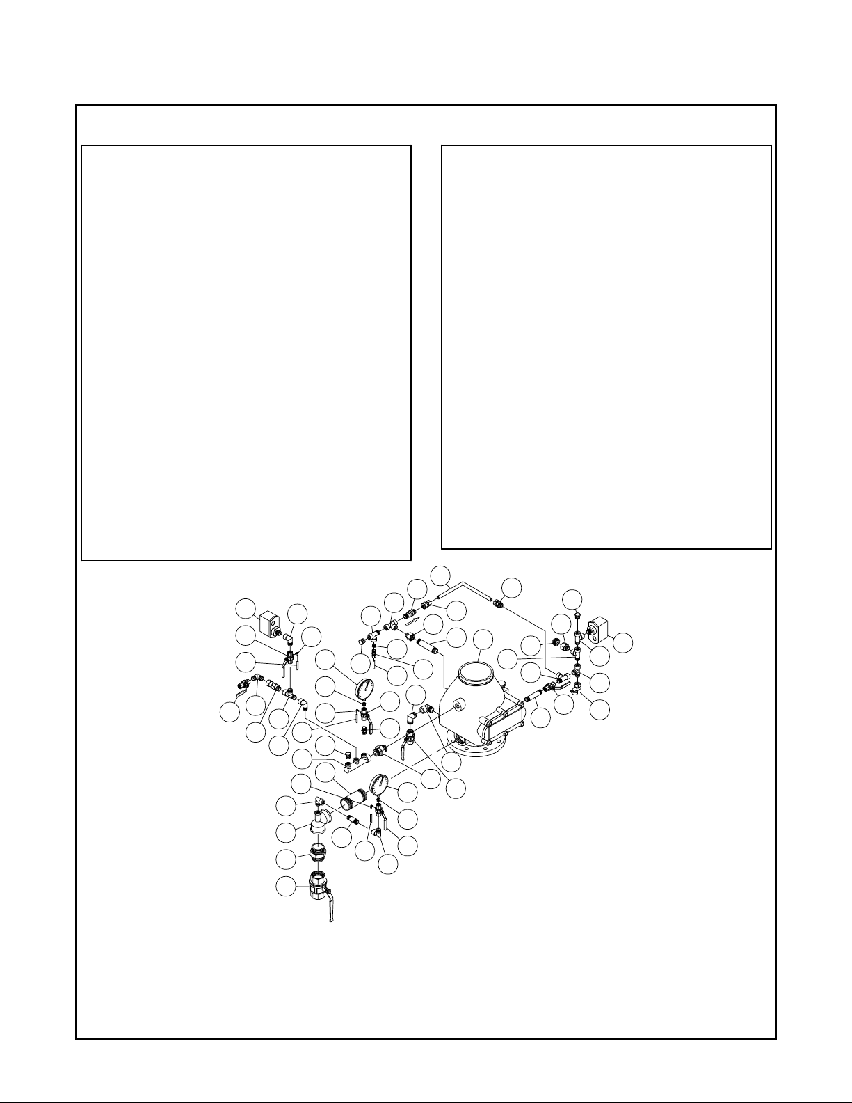
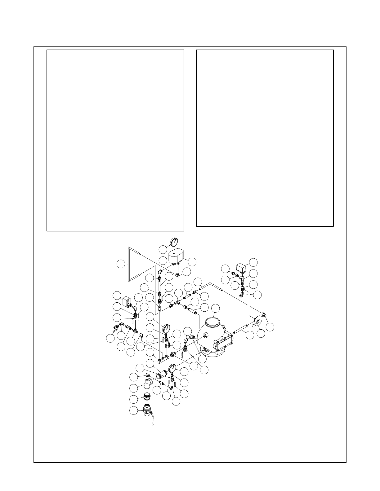
FIGURE 9
EUROPEAN CONFORMITY
DPV-1 DRY PIPE VALVE TRIM with THREE-WAY ALARM TEST VALVE
without ACC-1 ACCELERATOR
— DN150 —
Page 15
TFP1090
Page 15 of 22
DESCRIPTIONNO.
025500013; Water gauge; 1/4" npt; 300 psi
1
2
1610000210; Ball valve; brass; full bore; 1/2" BSP; PN30;
kv=16.3; pr
1610000270; Ball valve; brass; full bore; 3/4" BSP; PN30;
3
kv=29.5; pr
4
1610000600; Ball valve; brass; full bore; 2" BSP; PN25;
kv=265; ur
5
2162156; Automatic drain valve; 1/2";
oper: k=25 & non oper: k=5
260; Alarm pressure switch
6
7
262; Low pressure switch
8
305105; Check valve brass thread;
DN15 male x DN15 fem.; nickel plated
406012; Elbow 3 mm x m5
9
10
Dry pipe valve; DPV-1; ductile iron; 4"
11
59304FO; Ball valve; size 1/2"; full bore; PN40;
venthole threaded
12
920321002; Fitting anti flood; 3/32"
13
923431012; Air pressure gauge;
300 psi; 1/4" npt
14
A130RIID2; malleable fitt.; reducing tee; BSP thread 2" x 2"
15
A280I2; malleable fitting; nipple male; BSP thread;
size 2"; galvanized
16
A291E2; malleable fitting; plug male; BSP thread;
size 3/4"; galvanized
17
AP100D4; pipe nipple; stainless steel 316; size 1/2";
length 100 mm
AP100E4; pipe nipple; stainless steel 316; size 3/4";18 36
length 100 mm
AP120I2; pipe nipple; steel; size 2"; length 120 mm;
19
galvanized
ATDDMN;Adapter fitting; brass;
20
thread DN15 x DN15 male; nickel pl.
ATDFCON;Adapter fitting; brass;
21
thread DN15 fem. x compr.15 mm; n.
..........................................
..........................................
...........................................
.............................
.............................
...............................
..............................
.....................................
......................................
....................................
...................................
.......................................
.......................................
..........................................
.................
.....................
.....................
........................
......................
.....................
QTY. NO.
1
2
1
1
1
1
1
1
329
1
3
1
1
....1
1
1
1
1
1
3
1
DESCRIPTION
ATDMCON;Adapter fitting; brass;
22
thread DN15 male x compr.15 mm; n.
ETDDMN; Adapter elbow; brass;
23
thread DN15 male x DN15 male; nickel pl.
ETDMDFN; Adapter elbow; brass;
24
thread DN15 male x DN15fem.; nickel pl.
ETDMDFN; Adapter elbow; brass;
25
thread DN15 male x DN15fem.; nickel pl.
ETEMEFN; Adapter elbow; brass;
26
thread DN20 male x DN20 fem.; nickel pl.
MANIF3WAY; Manifold; threaded; nickel plated brass;
27
DN25 x DN15
PTDN; Plug; brass; thread DN15 male; nickel plated
28
RTDMBFN; Adapter reduce; brass;
thread DN15 male x DN8 fem.; nickel pl.
RTDMEFN; Adapter reduce; brass;
30
thread DN15 male x DN20 fem.; n.
RTEMDFN; Adapter reduce; brass;
31
thread DN20 male x DN15 fem.; n.
TTDDDFN; adapter tee; brass;
32
thread DN15 fem x DN15 fem x DN15 fem; nickel pl.
TTDDMDFN; adapter tee; brass;
33
thread DN15 male x DN15 male x DN15 fem; n.
TTDMDDFN; adapter tee; brass;
34
thread DN15 male x DN15 fem x DN15 fem; nickel pl.
UTFFMN; Adapter union; brass;
35
thread DN25 x DN25 male; nickel plated
V923221002; Check valve brass;
NPT 1/2" male/male; seat buna-n
WS00000004; Pressure relief hose;
37
3 x 6 length 1.2 m; transparent
WS00000008; Copper pipe 6 mm; length 1 meter
38
WS00000082; Nickel pl.c opp. tube 15 x 1 mm
39
type B for DPV-1 DN100
........................................
........................
........................
.........................
...........................
................................
.....................
..................
...................
...................
..................
..........
...................
..........
.............
.........
...................
............
QTY.
1
1
1
3
2
1
2
4
1
1
1
2
3
1
1
3
1
1
25
29
29
12
7
28
34
32
31
39
21
22
20
36
16
34
5
11
23
2
30
33
25
24
34
33
38
25
1
9
37
13
9
378
28
26
18
26
3
17
2
6
29
11
35
27
20
9
37
20
19
10
29
11
14
15
4
FIGURE 10
EUROPEAN CONFORMITY
DPV-1 DRY PIPE VALVE TRIM with STANDARD ALARM TEST VALVE
without ACC-1 ACCELERATOR
— DN100 —
Page 16
Page 16 of 22
TFP1090
NO.
DESCRIPTION
025500013; Water gauge; 1/4" npt; 300 psi
1
1610000210; Ball valve; brass; full bore; 1/2" BSP; PN30;
2
kv=16.3; pr
1610000270; Ball valve; brass; full bore; 3/4" BSP; PN30;
3
kv=29.5; pr
1610000600; Ball valve; brass; full bore; 2" BSP; PN25;
4
kv=265; ur
2162156; Automatic drain valve; 1/2";
5
oper: k=25 & non oper: k=5
260; Alarm pressure switch
6
262; Low pressure switch
7
305105; Check valve brass thread;
8
DN15 male x DN15 fem.; nickel plated
9
406012; Elbow 3 mm x m5
Dry pipe valve; DPV-1; ductile iron; 6"
10
59304FO; Ball valve; size 1/2"; full bore; PN40;
11
venthole threaded
920321002; Fitting anti flood; 3/32"
12
923431012; Air pressure gauge;
13
300 psi; 1/4" npt
A130RIID2; malleable fitt.; reducing tee; BSP thread 2" x 2"
14
A280I2; malleable fitting; nipple male; BSP thread;15 33
size 2"; galvanized
A291E2; malleable fitting; plug male; BSP thread;
16
size 3/4"; galvanized
AP100I2; pipe nipple; steel; size 2"; length 100 mm;
17
galvanized
AP120D4; pipe nipple; stainless steel 316; size 1/2";
18
length 120 mm
AP120E4; pipe nipple; stainless steel 316; size 3/4";
19
length 120 mm
AP60D4; pipe nipple; stainless steel 316; size 1/2";
20
length 60 mm
ATDDMN;Adapter fitting; brass;
21
thread DN15 x DN15 male; nickel pl.
..........................................
..........................................
...........................................
.............................
.............................
...............................
..............................
.....................................
......................................
....................................
...................................
...........................................
.......................................
.......................................
........................................
.................
.....................
.....................
........................
......................
QTY.
1
2
1
125
1
1
1
1
3
1
3
1
1
....
1
1
1
1
1
1
1
1
DESCRIPTION
NO.
ATDFCON;Adapter fitting; brass;
22
thread DN15 fem. x compr.15 mm; n.
ATDMCON;Adapter fitting; brass;
23
thread DN15 male x compr.15 mm; n.
ETDDMN; Adapter elbow; brass;
24
thread DN15 male x DN15 male; nickel pl.
ETDMDFN; Adapter elbow; brass;
thread DN15 male x DN15fem.; nickel pl.
ETEEMN; Adapter elbow; brass;
26
thread DN20 male x DN20 male; nickel pl.
ETEMEFN; Adapter elbow; brass;
27
thread DN20 male x DN20 fem.; nickel pl.
MANIF3WAY; Manifold; threaded; nickel plated brass;
28
DN25 x DN15
PTDN; Plug; brass; thread DN15 male; nickel plated
29
RTDMBFN; Adapter reduce; brass;
30
thread DN15 male x DN8 fem.; nickel pl.
RTDMEFN; Adapter reduce; brass;
31
thread DN15 male x DN20 fem.; n.
TTDDDFN; adaptertee; brass;
32
thread DN15 fem x DN15 fem x DN15 fem; nickel pl.
TTDDMDFN; adaptertee; brass;
thread DN15 male x DN15 male x DN15 fem; n.
TTDMDDFN; adaptertee; brass;
34
thread DN15 male x DN15 fem x DN15 fem; nickel pl.
UTFFMN; Adapter union; brass;
35
thread DN25 x DN25 male; nickel plated
V923221002; Check valve brass;
36
NPT 1/2" male/male; seat buna-n
WS00000004; Pressure relief hose;
37
3 x 6 length 1.2 m; transparent
WS00000008; Copper pipe 6 mm; length 1 meter
38
WS00000088; Nickel pl. copp. tube 15 x 1 mm
39
type D for DPV-1 DN150
........................................
........................
.........................
...........................
................................
.....................
.....................
..................
...................
..................
..................
..........
...................
..........
.............
.........
...................
............
QTY.
1
1
1
4
1
1
1
3
3
2
1
2
4
1
1
3
1
1
7
11
37
24
2
33
837
25
25
14
15
4
39
36
25
9
13
30
9
29
28
17
9
20
32
34
30
29
38
11
21
1
30
37
11
25
22
31
19
12
26
27
35
3
23
10
16
34
34
29
31
34
33
2
18
5
FIGURE 11
EUROPEAN CONFORMITY
DPV-1 DRY PIPE VALVE TRIM with STANDARD ALARM TEST VALVE
without ACC-1 ACCELERATOR
— DN150 —
6
Page 17
TFP1090
Page 17 of 22
DESCRIPTIONNO.
025500013; Water gauge; 1/4" npt; 300 psi
1
1610000210; Ball valve; brass; full bore; 1/2" BSP; PN30;
2
kv=16.3; pr
1610000270; Ball valve; brass; full bore; 3/4" BSP; PN30;
3
kv=29.5; pr
1610000600; Ball valve; brass; full bore; 2" BSP; PN25;
4
kv=265; ur
2162156; Automatic drain valve; 1/2";
5
oper: k=25 & non oper: k=5
260; Alarm pressure switch
6
7
262; Low pressure switch
305105; Check valve brass thread;
8
DN15 male x DN15 fem.; nickel plated
406012; Elbow 3 mm x m5
9
Dry pipe valve; DPV-1; ductile iron; 4"
10
523111001; Accelerator;ACC-1
11
59304FO; Ball valve; size 1/2"; full bore; PN40;
12
venthole threaded
13
923431012; Air pressure gauge;
300 psi; 1/4" npt
A130RIID2; malleable fitt.; reducing tee; BSP thread 2" x 2"
14
A280I2; malleable fitting; nipple male; BSP thread;
15
size 2"; galvanized
16
A291E2; malleable fitting; plug male; BSP thread;
size 3/4"; galvanized
17
AP100E4; pipe nipple; stainless steel 316; size 3/4";
length 100 mm
AP120I2; pipe nipple; steel; size 2"; length 120 mm;18 37
galvanized
19
AP180D4; pipe nipple; stainless steel 316; size 1/2";
length 180 mm
AP60D4; pipe nipple; stainless steel 316; size 1/2";
20
length 60 mm
21
AP80D4; pipe nipple; stainless steel 316; size 1/2";
length 80 mm
ATDDMN;Adapter fitting; brass;
22
thread DN15 x DN15 male; nickel pl.
..........................................
..........................................
...........................................
.............................
.............................
...............................
..............................
..........................
.....................................
......................................
....................................
...................................
.......................................
..........................................
.......................................
........................................
........................................
.................
.....................
.....................
......................
QTY. NO.
1
2
1
1
1
1
1
1
330
1
1
3
2
....1
1
1
1
1
1
1
1
4
DESCRIPTION
ATDFCON;Adapter fitting; brass;
23
thread DN15 fem. x compr.15 mm; n.
ATDMCON;Adapter fitting; brass;
24
thread DN15 male x compr.15 mm; n.
ETDDMN; Adapter elbow; brass;
25
thread DN15 male x DN15 male; nickel pl.
ETDMCON; Adapter elbow; brass;
26
thread DN15 male x compr.15 mm; nickel pl.
ETDMDFN; Adapter elbow; brass;
27
thread DN15 male x DN15fem.; nickel pl.
ETEMEFN; Adapter elbow; brass;
28
thread DN20 male x DN20 fem.; nickel pl.
K00128; Alarm test/shut off valve; PN40; 1/2"; BSP; 3 way
29
MANIF3WAY; Manifold; threaded; nickel plated brass;
DN25 x DN15
RTDMBFN; Adapter reduce; brass;
31
thread DN15 male x DN8 fem.; nickel pl.
RTDMEFN; Adapter reduce; brass;
32
thread DN15 male x DN20 fem.; n.
RTEMDFN; Adapter reduce; brass;
33
thread DN20 male x DN15 fem.; n.
TTDDDFN; adapter tee; brass;
34
thread DN15 fem x DN15 fem x DN15 fem; nickel pl.
TTDDMDFN; adapter tee; brass;
35
thread DN15 male x DN15 male x DN15 fem; n.
UTFFMN; Adapter union; brass;
36
thread DN25 x DN25 male; nickel plated
WS00000004; Pressure relief hose;
3 x 6 length 1.2 m; transparent
WS00000082; Nickel pl.c opp. tube 15 x 1 mm
38
type B for DPV-1 DN100
WS00000083; Nickel pl. copp. tube 15 x 1 mm
39
type C for DPV-1 DN100
WS00000086; Nickel pl.c opp. tube 15 x 1 mm
40
type B for DPV-1 DN150
........................................
................................
................................
................................
.....................
.....................
..................
...................
..................
...................
........................
........................
...................
...........................
................
.....
..........
.............
QTY.
1
3
1
2
5
2
1
1
2
1
1
2
2
1
3
1
1
1
39
24
7
27
34
38
23
22
21
2
27
6
16
32
35
27
27
33
12
25
8
34
22
5
26
9
37
2
9
35
37
27
20
28
17
28
3
29
13
11
26
24
40
24
13
31
12
36
30
22
19
9
37
22
18
10
31
12
14
15
FIGURE 12
EUROPEAN CONFORMITY
DPV-1 DRY PIPE VALVE TRIM with THREE-WAY ALARM TEST VALVE
with ACC-1 ACCELERATOR
— DN100 —
1
4
Page 18
Page 18 of 22
TFP1090
NO. DESCRIPTION
1
025500013; Water gauge; 1/4" npt; 300 psi
2
1610000210; Ball valve; brass; full bore; 1/2" BSP; PN30;
kv=16.3; pr
1610000270; Ball valve; brass; full bore; 3/4" BSP; PN30;
3
kv=29.5; pr
1610000600; Ball valve; brass; full bore; 2" BSP; PN25;
4
kv=265; ur
2162156; Automatic drain valve; 1/2";
5
oper: k=25 & non oper: k=5
260; Alarm pressure switch
6
262; Low pressure switch
7
305105; Check valve brass thread;
8
DN15 male x DN15 fem.; nickel plated
406012; Elbow 3 mm x m5
9
Dry pipe valve; DPV-1; ductile iron; 6"
10
523111001; Accelerator; ACC-1
11
59304FO; Ball valve; size 1/2"; full bore; PN40;
12
venthole threaded
923431012; Air pressure gauge;
13
300 psi; 1/4" npt
A130RIID2; malleable fitt.; reducing tee; BSP thread 2" x 2"
14
A280I2; malleable fitting; nipple male; BSP thread;
15
size 2"; galvanized
A291E2; malleable fitting; plug male; BSP thread;
16
size 3/4"; galvanized
17
AP100D4; pipe nipple; stainless steel 316; size 1/2";
length 100 mm
AP100I2; pipe nipple; steel; size 2"; length 100 mm;
18
galvanized
AP120E4; pipe nipple; stainless steel 316; size 3/4";
19
length 120 mm
AP180D4; pipe nipple; stainless steel 316; size 1/2";
20
AP60D4; pipe nipple; stainless steel 316; size 1/2";
21
length 60 mm
ATDDMN;Adapter fitting; brass;
22
thread DN15 x DN15 male; nickel pl.
..........................................
..........................................
...........................................
.............................
.............................
...............................
..............................
.....................................
......................................
....................................
...................................
.......................................
...........................................
.......................................
.......................................1length 180 mm 39
........................................
.....................
.....................
..........................
......................
.................
....
QTY.
1
2
1
1
1
1
1
1
3
1
1
3
2
1
1
1
1
1
1
2
2
NO.
DESCRIPTION
23
ATDFCON;Adapter fitting; brass;
thread DN15 fem. x compr.15 mm; n.
24
ATDMCON;Adapter fitting; brass;
thread DN15 male x compr.15 mm; n.
25
ETDDMN; Adapter elbow; brass;
thread DN15 male x DN15 male; nickel pl.
26
ETDMCON; Adapter elbow; brass;
thread DN15 male x compr.15 mm; nickel pl.
27
ETDMDFN; Adapter elbow; brass;
thread DN15 male x DN15fem.; nickel pl.
28
ETEEMN; Adapter elbow; brass;
thread DN20 male x DN20 male; nickel pl.
29
ETEMEFN; Adapter elbow; brass;
thread DN20 male x DN20 fem.; nickel pl.
30
MANIF3WAY; Manifold; threaded; nickel plated brass;
DN25 x DN15
31
RTDMBFN; Adapter reduce; brass;
thread DN15 male x DN8 fem.; nickel pl.
32
RTDMEFN; Adapter reduce; brass;
thread DN15 male x DN20 fem.; n.
33
TTDDDFN; adaptertee; brass;
thread DN15 fem x DN15 fem x DN15 fem; nickel pl.
34
TTDDMDFN; adaptertee; brass;
thread DN15 male x DN15 male x DN15 fem; n.
35
UTFFMN; Adapter union; brass;
thread DN25 x DN25 male; nickel plated
36
WS00000004; Pressure relief hose;
3 x 6 length 1.2 m; transparent
37
WS00000086; Nickel pl.c opp. tube 15 x 1 mm
type B for DPV-1 DN150
38
WS00000087; Nickel pl. copp. tube 15 x 1 mm
type C for DPV-1 DN150
WS00000088; Nickel pl. copp. tube 15 x 1 mm
type D for DPV-1 DN150
40
WS00000095; Alarm test/shut off valve; PN40; 1/2";
BSP; 3 way
........................................
........................
...........................
................................
................................
................................
..........................................
.....................
.....................
..................
................
...................
..................
..................
...................
..........
.............
...................
QTY.
1
3
1
2
5
1
1
1
2
2
2
2
1
3
1
1
1
1
38
7
12
36
25
2
34
836
27
27
14
15
13
27
24
24
21
27
9
13
31
30
18
9
4
37
2
24
9
21
36
11
26
39
17
33
12
22
1
31
12
27
23
32
19
28
29
35
3
16
32
22
10
6
33
34
5
26
40
20
FIGURE 13
EUROPEAN CONFORMITY
DPV-1 DRY PIPE VALVE TRIM with THREE-WAY ALARM TEST VALVE
with ACC-1 ACCELERATOR
— DN150 —
Page 19

TFP1090
Page 19 of 22
NO. DESCRIPTION
1
025500013; Water gauge; 1/4" npt; 300 psi
2
1610000210; Ball valve; brass; full bore; 1/2" BSP; PN30;
kv=16.3; pr
3
1610000270; Ball valve; brass; full bore; 3/4" BSP; PN30;
kv=29.5; pr
4
1610000600; Ball valve; brass; full bore; 2" BSP; PN25;
kv=265; ur
5
2162156; Automatic drain valve; 1/2";
oper: k=25 & non oper: k=5
6
260; Alarm pressure switch
7
262; Low pressure switch
8
305105; Check valve brass thread;
DN15 male x DN15 fem.; nickel plated
9
406012; Elbow 3 mm x m5
10
Dry pipe valve; DPV-1; ductile iron; 4"
11
523111001; Accelerator; ACC-1
12
59304FO; Ball valve; size 1/2"; full bore; PN40;
venthole threaded
13
920321002; Fitting anti flood; 3/32"
14
923431012; Air pressure gauge;
300 psi; 1/4" npt
15
A130RIID2; malleable fitt.; reducing tee; BSP thread 2" x 2"
16
A280I2; malleable fitting; nipple male; BSP thread;
size 2"; galvanized
17
A291E2; malleable fitting; plug male; BSP thread;
size 3/4"; galvanized
18
AP100D4; pipe nipple; stainless steel 316; size 1/2";
length 100 mm
AP100E4; pipe nipple; stainless steel 316; size 3/4";
19
length 100 mm
AP120I2; pipe nipple; steel; size 2"; length 120 mm;
20
galvanized
AP60D4; pipe nipple; stainless steel 316; size 1/2";21 41
length 60 mm
ATDDMN;Adapter fitting; brass;
22
thread DN15 x DN15 male; nickel pl.
ATDFCON;Adapter fitting; brass;23
thread DN15 fem. x compr.15 mm; n.
ATDMCON;Adapter fitting; brass;
24
thread DN15 male x compr.15 mm; n.
..........................................
..........................................
...........................................
.............................
.............................
...............................
..............................
..........................
.....................................
......................................
....................................
...................................
.......................................
.......................................
..........................................
........................................
.................
.....................
.....................
........................
......................
.....................
.....................
....
QTY.
1
3
1
1
1
1
1
1
3
1
1
3
2
1
1
1
1
1
1
2
3
1
1
NO.
DESCRIPTION
25
ATDMCON;Adapter fitting; brass;
thread DN15 male x compr.15 mm; n.
26
ETDDMN; Adapter elbow; brass;
thread DN15 male x DN15 male; nickel pl.
27
ETDMCON; Adapter elbow; brass;
thread DN15 male x compr.15 mm; nickel pl.
28
ETDMDFN; Adapter elbow; brass;
thread DN15 male x DN15fem.; nickel pl.
29
ETDMDFN; Adapter elbow; brass;
thread DN15 male x DN15fem.; nickel pl.
30
ETEMEFN; Adapter elbow; brass;
thread DN20 male x DN20 fem.; nickel pl.
31
MANIF3WAY; Manifold; threaded; nickel plated brass;
DN25 x DN15
32
RTDMBFN; Adapter reduce; brass;
thread DN15 male x DN8 fem.; nickel pl.
33
RTDMEFN; Adapter reduce; brass;
thread DN15 male x DN20 fem.; n.
341
RTEMDFN; Adapter reduce; brass;
thread DN20 male x DN15 fem.; n.
35
TTDDDFN; adapter tee; brass;
thread DN15 fem x DN15 fem x DN15 fem; nickel pl.
36
TTDDMDFN; adapter tee; brass;
thread DN15 male x DN15 male x DN15 fem; n.
37
TTDMDDFN; adapter tee; brass;
thread DN15 male x DN15 fem x DN15 fem; nickel pl.
38
UTFFMN; Adapter union; brass;
thread DN25 x DN25 male; nickel plated
39
V923221002; Check valve brass;
NPT 1/2" male/male; seat buna-n
40
WS00000004; Pressure relief hose;
3 x 6 length 1.2 m; transparent
WS00000008; Copper pipe 6 mm; length 1 meter
WS00000082; Nickel pl.c opp. tube 15 x 1 mm
42
type B for DPV-1 DN100
WS00000083; Nickel pl. copp. tube 15 x 1 mm
43
type C for DPV-1 DN100
WS00000086; Nickel pl.c opp. tube 15 x 1 mm
44
type B for DPV-1 DN150
........................................
........................
........................
.........................
...........................
................................
................................
................................
.....................
..................
................
...................
...................
..................
...................
..........
.............
.........
...................
............1
QTY.
3
1
1
1
4
2
1
4
1
1
1
2
3
1
1
3
1
1
1
29
32
43
25
7
37
35
34
42
23
24
22
39
17
12
26
2
33
37
5
36
29
28
37
36
32
13
41
29
29
9
40
2
9
408
21
30
19
3
30
18
2
6
14
11
27
25
44
25
14
32
12
38
31
22
9
40
22
20
10
1
32
12
15
16
4
FIGURE 14
EUROPEAN CONFORMITY
DPV-1 DRY PIPE VALVE TRIM with STANDARD ALARM TEST VALVE
with ACC-1 ACCELERATOR
— DN100 —
Page 20
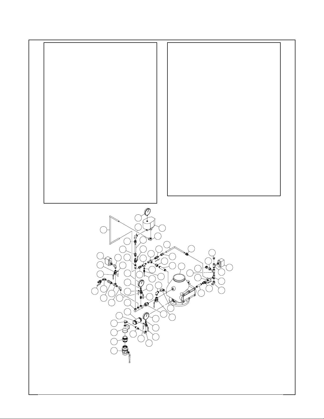
Page 20 of 22
TFP1090
NO.
DESCRIPTION
025500013; Water gauge; 1/4" npt; 300 psi
1
1610000210; Ball valve; brass; full bore; 1/2" BSP; PN30;
2
kv=16.3; pr
1610000270; Ball valve; brass; full bore; 3/4" BSP; PN30;
3
kv=29.5; pr
1610000600; Ball valve; brass; full bore; 2" BSP; PN25;
4
kv=265; ur
2162156; Automatic drain valve; 1/2";
5
oper: k=25 & non oper: k=5
260; Alarm pressure switch
6
7
262; Low pressure switch
305105; Check valve brass thread;
8
DN15 male x DN15 fem.; nickel plated
9
406012; Elbow 3 mm x m5
10
Dry pipe valve; DPV-1;ductile iron; 6"
523111001; Accelerator; ACC-1
11
12
59304FO; Ball valve; size 1/2"; full bore; PN40;
venthole threaded
13
920321002; Fitting anti flood; 3/32"
14
923431012; Air pressure gauge;
300 psi; 1/4" npt
A130RIID2; malleable fitt.; reducing tee; BSP thread 2" x 2"
15
16
A280I2; malleable fitting; nipple male; BSP thread;
size 2"; galvanized
A291E2; malleable fitting; plug male; BSP thread;
17
size 3/4"; galvanized
AP100I2; pipe nipple; steel; size 2"; length 100 mm;
18
galvanized
AP120D4; pipe nipple; stainless steel 316; size 1/2";
19
length 120 mm
AP120E4; pipe nipple; stainless steel 316; size 3/4";
20
length 120 mm
AP60D4; pipe nipple; stainless steel 316; size 1/2";
21
length 60 mm
ATDDMN;Adapter fitting; brass;
22
ATDFCON;Adapter fitting; brass;
23
thread DN15 fem. x compr.15 mm; n.
24
ATDMCON;Adapter fitting; brass;
thread DN15 male x compr.15 mm; n.
..........................................
..........................................
...........................................
.............................
.............................
...............................
..............................
.....................................
......................................
....................................
...................................
...........................................
.......................................
.......................................
........................................
.....................
.....................
..........................
........................
......................1thread DN15 x DN15 male; nickel pl.
.....................
.....................
.................
....1 36
DESCRIPTION
QTY.
1
3
1
128
1
1
1
1
3
1
1
3
1
2
1
1
1
1
1
2
1
1
NO.
ATDMCON;Adapter fitting; brass;
25
thread DN15 male x compr.15 mm; n.
ETDDMN; Adapter elbow;brass;
26
thread DN15 male x DN15 male; nickel pl.
ETDMCON; Adapter elbow; brass;
27
thread DN15 male x compr.15 mm; nickel pl.
ETDMDFN; Adapterelbow; brass;
thread DN15 male x DN15fem.; nickel pl.
ETEEMN; Adapterelbow; brass;
29
thread DN20 male x DN20 male; nickel pl.
ETEMEFN; Adapter elbow; brass;
30
thread DN20 male x DN20 fem.; nickel pl.
MANIF3WAY; Manifold; threaded; nickel plated brass;
31
DN25 x DN15
PTDN; Plug; brass; thread DN15 male; nickel plated
32
RTDMBFN; Adapter reduce; brass;
33
thread DN15 male x DN8 fem.; nickel pl.
RTDMEFN; Adapter reduce; brass;
34
thread DN15 male x DN20 fem.; n.
TTDDDFN; adaptertee; brass;
35
thread DN15 fem x DN15 fem x DN15 fem; nickel pl.
TTDDMDFN; adaptertee; brass;
thread DN15 male x DN15 male x DN15 fem; n.
TTDMDDFN; adaptertee; brass;
37
thread DN15 male x DN15 fem x DN15 fem; nickel pl.
UTFFMN; Adapter union; brass;
38
thread DN25 x DN25 male; nickel plated
V923221002; Check valve brass;
39
NPT 1/2" male/male; seat buna-n
WS00000004; Pressure relief hose;
40
3 x 6 length 1.2 m; transparent
WS00000008; Copper pipe 6 mm; length 1 meter
41
WS00000086; Nickel pl.c opp. tube 15 x 1 mm
42
type B for DPV-1 DN150
WS00000087; Nickel pl. copp. tube 15 x 1 mm
43
type C for DPV-1 DN150
WS00000088; Nickel pl. copp. tube 15 x 1 mm
44
type D for DPV-1 DN150
.....................
..................
................
...................
..................
..................
........................................
...................
........................
...................
.........................
...........................
................................
................................1
................................
..........
..........
.............
.........
............
QTY.
3
1
1
5
1
1
1
1
3
2
1
2
4
1
1
3
1
1
1
14
43
7
12
40
26
2
36
840
28
28
15
16
28
42
25
24
21
28
9
33
31
18
9
4
2
37
1
25
9
21
40
11
27
44
39
35
33
41
12
22
33
12
28
23
34
20
13
29
30
38
1
3
25
10
37
32
34
17
37
2
19
6
37
36
5
FIGURE 15
EUROPEAN CONFORMITY
DPV-1 DRY PIPE VALVE TRIM with STANDARD ALARM TEST VALVE
with ACC-1 ACCELERATOR
— DN150 —
Page 21

TFP1090
Page 21 of 22
Ordering
Procedure
Model DPV-1 Dry Pipe Valve
with Assembled European
Conformity Valve Trim
Specify: Fully Assembled Model DPV1 Dry Pipe Valve with European Conformity Valve Trim, P/N (Table D).
Accessories
Specify: (“description”) and P/N.
• “Supervisory Switch” for accelerator
control valve,
P/N CEDPV1ASS.
• “SupervisorySwitch” forwatermotor
alarm control valve,
P/N CEDPV1ASS.
DRY PIPE
VALVE
27 Flanged/Flanged, PN10/16
28 Flanged/Grooved, PN10/16
29 Flanged/Flanged,ANSI
• “Air Pressure Relief Valve set at 3,1
bar”, P/N 92-343-1-020.
• “Model WMA-1 Water Motor Alarm
with Red Finish Gong”,
P/N 52-630-2-021.
• “A thru Z” Labels for attaching to
valve trim components,
P/N WS00000033.
P/N XX X XX XX X XX
STOP VALVE
00
TO BE ORDERED
SEPARATELY
SWITCH
0
NONE
1 PS10-1A
2A Flanged/Grooved, ANSI
2B Grooved/Grooved
SIZE
4
6 6" (168,3 mm)
EUR/FM w/3-way Alarm Control Valve88
89 EUR/FM w/Std. Alarm Test Valve
4"
6" (165,1 mm)7
TRIM
ACCESSORIES
00
European Conformity Trim with:
01
- Accelerator
- Accelerator control valve
European Conformity Trim with:
49
- Low pressure switch PS40-1A
- No accelerator
- No accelerator control valve
European Conformity Trim with:
50
- Low pressure switch PS40-1A
- Accelerator
- Accelerator control valve
TABLE D
MODEL DPV-1 DRY PIPE VALVE
WITH EUROPEAN CONFORMITY VALVE TRIM
— FULLY ASSEMBLED —
NONE
Page 22

Page 22 of 22
TFP1090
TYCO FIRE & BUILDING PRODUCTS, 451 North Cannon Avenue, Lansdale, Pennsylvania 19446
Page 23

Appendix A of TFP1090 (09/2005)
Summary Instructions (If problems occur, consult full document)
Dry Pipe Valve, DPV-1, DN100, Three-Way Alarm Test, Without Accelerator
J
K
M
E
L
A
400 mm 400 mm
I. Normal conditions:
• Themain control valve (A) is opened
and locked.
• Thesprinkler system is filled with air
and is pressurized.
• The main drain valve (F), and low
body drain valve (L) are closed.
• The three-way alarm control valve
(E) is in the open position.
• The pressure gauge valves (B) and
(C) are open.
• The pressure switch valve (J) is
open.
• The air supply control valve (K) is
open.
• System air pressure gauge (G)
reads downstream air pressure.
• Water supply pressure gauge (H)
reads the upstream water pressure.
II. Operation
When one or more sprinklers are activated, air pressure is reduced downstream of the drypipe valve. When the
airpressureis sufficientlyreduced,the
water pressure overcomes the differentialholdingthe dry pipevalve closed
and the dry pipe valve opens to permit
water flow into the system piping and
to be discharged from any open sprinklers. Also, with the dry pipe valve
open, water flows through the alarm
port at the rear of the dry pipe valve to
actuate the waterflow pressure alarm
switch (M) and, as applicable, the
water motor alarm.
D
PGC
H
B
F
III. Removing system from service:
Step 1. Close the main control valve
(A), close the air supply control valve
(K), and place the three-way alarm
controlvalve (E) in theclosedposition.
Step2. Drain the system with the main
drain valve (F) andby opening all auxiliary drain valves in the system to
make sure that cross-mains and
branch lines are drained.
IV. Placing the system back in service:
Step 1. Close the auxiliary drain
valves after water ceases to discharge,andleavethemain drain valve
(F) open.
Step 2. Place the thre e-way alarm
control valve (E) in the open position.
Step 3. Replace the sprinklers that
haveoperated and the sprinklersclose
to the fire.
Step 4. Push down on the reset knob
(P) to allow the dry pipe valve (D) to
reseat.
Step 5. Viathe air supply control valve
(K) pressurize the system with air to
0,7 bar, and then open and close each
auxiliary drain valves in the system
piping to drain any remaining water in
trapped sections. Also, partially open
the low body drain valve (L) to assure
that the riser is completely drained.
Close the low body drain valve (L) as
soon as water ceases to discharge.
Step 6. Open the air supply control
valve (K) to restore the system to the
normal system air pressure.
N
465 mm
195 mm
Step 7. Partially open the main control
valve (A), and then slowly close the
main drain valve (F).
Step 8. Fully open the main control
valve (A) and lock it open.
Step 9. Reset the fire alarm panel and
notify the central alarm station.
V. Weekly test:
Important: Prior to closing any valves
or activating any alarms, notify local
security guards and the central alarm
station if applicable.
Step 1. Place the three-way alarm
control valve (E) in the test position,
verify that the alarm signal created by
the waterflow pressure alarm switch
(M) is visible at the fire panel. If applicable, check the sound of the water
motor alarm — it must be clear and
steady.
Step 2. Place the three-way alarm
control valve (E) in the open position
and verify that the normal supply and
system pressures are restored. If the
supply pressure is below the normal,
use the ins truc tions from the water
supply to obtain the usual pressure.
Step 3. Close the pr essure switch
valve ( J) and verify operation of the
low air pressur e alarm switch (N).
Step 4. Return the pressure switch
valve (J) to the normally open position
after verifying that the alarm signal is
visible at the fire panel.
Page 24

Appendix B of TFP1090 (09/2005)
Summary Instructions (If problems occur, consult full document)
Dry Pipe Valve, DPV-1, DN150, Three-Way Alarm Test, Without Accelerator
GC
J
K
H
B
F
A
415 mm
I. Normal conditions:
• Themain control valve (A) is opened
and locked.
• Thesprinkler system is filled with air
and is pressurized.
• The main drain valve (F), and low
body drain valve (L) are closed.
• The three-way alarm control valve
(E) is in the open position.
• The pressure gauge valves (B) and
(C) are open.
• The pressure switch valve (J) is
open.
• The air supply control valve (K) is
open.
• System air pressure gauge (G)
reads downstream air pressure.
• Water supply pressure gauge (H)
reads the upstream water pressure.
II. Operation
When one or more sprinklers are activated, air pressure is reduced downstream of the drypipe valve. When the
airpressureis sufficientlyreduced,the
water pressure overcomes the differentialholdingthe dry pipevalve closed
and the dry pipe valve opens to permit
water flow into the system piping and
to be discharged from any open sprinklers. Also, with the dry pipe valve
open, water flows through the alarm
port at the rear of the dry pipe valve to
actuate the waterflow pressure alarm
switch (M) and, as applicable, the
water motor alarm.
D
P
M
E
340 mm 210 mm
III. Removing system from service:
Step 1. Close the main control valve
(A), close the air supply control valve
(K), and place the three-way alarm
controlvalve (E) in theclosedposition.
Step2. Drain the system with the main
drain valve (F) andby opening all aux-
Step 7. Partially open the main control
valve (A), and then slowly close the
main drain valve (F).
Step 8. Fully open the main control
valve (A) and lock it open.
Step 9. Reset the fire alarm panel and
notify the central alarm station.
iliary drain valves in the system to
make sure that cross-mains and
branch lines are drained.
V. Weekly test:
Important: Prior to closing any valves
IV. Placing the system back in service:
Step 1. Close the auxiliary drain
valves after water ceases to discharge,andleavethemain drain valve
(F) open.
Step 2. Place the thre e-way alarm
control valve (E) in the open position.
Step 3. Replace the sprinklers that
haveoperated and the sprinklersclose
to the fire.
Step 4. Push down on the reset knob
(P) to allow the dry pipe valve (D) to
reseat.
Step 5. Viathe air supply control valve
(K) pressurize the system with air to
0,7 bar, and then open and close each
auxiliary drain valves in the system
piping to drain any remaining water in
trapped sections. Also, partially open
the low body drain valve (L) to assure
that the riser is completely drained.
Close the low body drain valve (L) as
soon as water ceases to discharge.
or activating any alarms, notify local
security guards and the central alarm
station if applicable.
Step 1. Place the three-way alarm
control valve (E) in the test position,
verify that the alarm signal created by
the waterflow pressure alarm switch
(M) is visible at the fire panel. If applicable, check the sound of the water
motor alarm — it must be clear and
steady.
Step 2. Place the three-way alarm
control valve (E) in the open position
and verify that the normal supply and
system pressures are restored. If the
supply pressure is below the normal,
use the ins truc tions from the water
supply to obtain the usual pressure.
Step 3. Close the pr essure switch
valve ( J) and verify operation of the
low air pressur e alarm switch (N).
Step 4. Return the pressure switch
valve (J) to the normally open position
after verifying that the alarm signal is
visible at the fire panel.
Step 6. Open the air supply control
valve (K) to restore the system to the
normal system air pressure.
N
510 mm
L
Page 25

Appendix C of TFP1090 (09/2005)
Summary Instructions (If problems occur, consult full document)
Dry Pipe Valve, DPV-1, DN100, Standard Alarm Test, Without Accelerator
CGP
D
J
H
K
N
M
E
L
A
I. Normal conditions:
• Themain control valve (A) is opened
and locked.
• Thesprinkler system is filled with air
and is pressurized.
• The main drain valve (F), and low
body drain valve (L) are closed.
• The alarm test valve (E) is in the
closed position.
• The pressure gauge valves (B) and
(C) are open.
• The pressure switch valve (J) is
open.
• The air supply control valve (K) is
open.
• System air pressure gauge (G)
reads downstream air pressure.
• Water supply pressure gauge (H)
reads the upstream water pressure.
II. Operation
When one or more sprinklers are activated, air pressure is reduced downstream of the drypipe valve. When the
airpressureis sufficientlyreduced,the
water pressure overcomes the differentialholdingthe dry pipevalve closed
and the dry pipe valve opens to permit
water flow into the system piping and
to be discharged from any open sprinklers. Also, with the dry pipe valve
open, water flows through the alarm
port at the rear of the dry pipe valve to
actuate the waterflow pressure alarm
switch (M) and, as applicable, the
water motor alarm.
B
F
400 mm365 mm
III. Removing system from service:
Step 1. Close the main control valve
(A), and close the air supply control
valve (K).
Step2. Drain the system with the main
drain valve (F) andby opening all auxiliary drain valves in the system to
make sure that cross-mains and
branch lines are drained.
IV. Placing the system back in service:
Step 1. Close the auxiliary drain
valves after water ceases to discharge,andleavethemain drain valve
(F) open.
Step 2. Replace the sprinklers that
haveoperated and the sprinklersclose
to the fire.
Step 3. Push down on the reset knob
(P) to allow the dry pipe valve (D) to
reseat.
Step 4. Viathe air supply control valve
(K) pressurize the system with air to
0,7 bar, and then open and close each
auxiliary drain valves in the system
piping to drain any remaining water in
trapped sections. Also, partially open
the low body drain valve (L) to assure
that the riser is completely drained.
Close the low body drain valve (L) as
soon as water ceases to discharge.
Step 5. Open the air supply control
valve (K) to restore the system to the
normal system air pressure.
Step 6. Partially open the main control
valve (A), and then slowly close the
main drain valve (F).
465 mm
195 mm
Step 7. Fully open the main control
valve (A) and lock it open.
Step 8 . Reset the fire alarm panel and
notify the central alarm station.
V. Weekly test:
Important: Prior to closing any valves
or activating any alarms, notify local
security guards and the central alarm
station if applicable.
Step 1. Open the alarm test valve (E),
verify that the alarm signal created by
the waterflow pressure alarm switch
(M) is visible at the fire panel. If applicable, check the sound of the water
motor alarm — it must be clear and
steady.
Step 2. Close the alarm test valve (E),
verify that the normal supply and system pressures are restored. If the supply pressure is below the normal, use
the instructions from the water supply
to obtain the usual pressure.
Step 3. Close the pr essure switch
valve ( J) and verify operation of the
low air pressur e alarm switch (N).
Step 4. Return the pressure switch
valve (J) to the normally open position
after verifying that the alarm signal is
visible at the fire panel.
Page 26

Appendix D of TFP1090 (09/2005)
Summary Instructions (If problems occur, consult full document)
Dry Pipe Valve, DPV-1, DN150, Standard Alarm Test, Without Accelerator
GC
J
K
H
B
F
A
I. Normal conditions:
• Themain control valve (A) is opened
and locked.
• Thesprinkler system is filled with air
and is pressurized.
• The main drain valve (F), and low
body drain valve (L) are closed.
• The alarm test valve (E) is in the
closed position.
• The pressure gauge valves (B) and
(C) are open.
• The pressure switch valve (J) is
open.
• The air supply control valve (K) is
open.
• System air pressure gauge (G)
reads downstream air pressure.
• Water supply pressure gauge (H)
reads the upstream water pressure.
II. Operation
When one or more sprinklers are activated, air pressure is reduced downstream of the drypipe valve. When the
airpressureis sufficientlyreduced,the
water pressure overcomes the differentialholdingthe dry pipevalve closed
and the dry pipe valve opens to permit
water flow into the system piping and
to be discharged from any open sprinklers. Also, with the dry pipe valve
open, water flows through the alarm
port at the rear of the dry pipe valve to
actuate the waterflow pressure alarm
switch (M) and, as applicable, the
water motor alarm.
D
P
M
E
460 mm415 mm
III. Removing system from service:
Step 1. Close the main control valve
(A), and close the air supply control
valve (K).
Step2. Drain the system with the main
drain valve (F) andby opening all auxiliary drain valves in the system to
make sure that cross-mains and
branch lines are drained.
IV. Placing the system back in service:
Step 1. Close the auxiliary drain
valves after water ceases to discharge,andleavethemain drain valve
(F) open.
Step 2. Replace the sprinklers that
haveoperated and the sprinklersclose
to the fire.
Step 3. Push down on the reset knob
(P) to allow the dry pipe valve (D) to
reseat.
Step 4. Viathe air supply control valve
(K) pressurize the system with air to
0,7 bar, and then open and close each
auxiliary drain valves in the system
piping to drain any remaining water in
trapped sections. Also, partially open
the low body drain valve (L) to assure
that the riser is completely drained.
Close the low body drain valve (L) as
soon as water ceases to discharge.
Step 5. Open the air supply control
valve (K) to restore the system to the
normal system air pressure.
Step 6. Partially open the main control
valve (A), and then slowly close the
main drain valve (F).
N
510 mm
L
210 mm
Step 7. Fully open the main control
valve (A) and lock it open.
Step 8 . Reset the fire alarm panel and
notify the central alarm station.
V. Weekly test:
Important: Prior to closing any valves
or activating any alarms, notify local
security guards and the central alarm
station if applicable.
Step 1. Open the alarm test valve (E),
verify that the alarm signal created by
the waterflow pressure alarm switch
(M) is visible at the fire panel. If applicable, check the sound of the water
motor alarm — it must be clear and
steady.
Step 2. Close the alarm test valve (E),
verify that the normal supply and system pressures are restored. If the supply pressure is below the normal, use
the instructions from the water supply
to obtain the usual pressure.
Step 3. Close the pr essure switch
valve ( J) and verify operation of the
low air pressur e alarm switch (N).
Step 4. Return the pressure switch
valve (J) to the normally open position
after verifying that the alarm signal is
visible at the fire panel.
Page 27
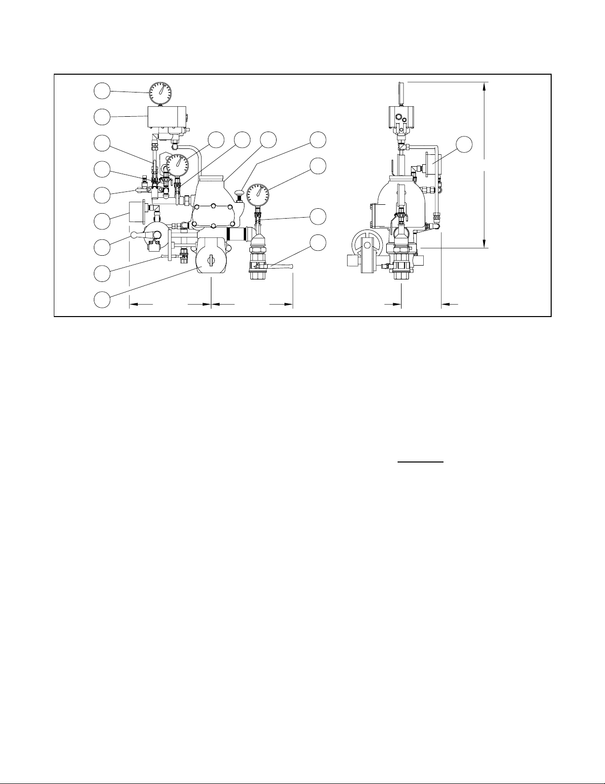
Appendix E of TFP1090 (09/2005)
Summary Instructions (If problems occur, consult full document)
Dry Pipe Valve, DPV-1, DN100, Three-Way Alarm Test, With Accelerator
R
Q
S
J
K
M
E
L
A
400 mm
I. Normal conditions:
• Themain control valve (A) is opened
andlocked, and the accelerator control valve (S) and air supply control
valve (K) are open.
• Thesprinkler system is filled with air
and is pressurized.
• The main drain valve (F), and low
body drain valve (L) are closed.
• The three-way alarm control valve
(E) is in the open position.
• The pressure gauge valves (B) and
(C) are open.
• The pressure switch valve (J) is
open.
• System air pressure gauge (G)
reads downstream air pressure,
water supply pr essure gauge (H)
reads the upstream water pressure,
and accelerator air pressure gauge
(R) reads the accelerator pressure.
II. Operation
When one or more sprinklers are activated, the accelerator operatesto permit system air pressure into the dry
pipe valve intermediate chamber. Doing so will immediately overcome the
ability of the system air pressure to
hold the dry pipe valve closed without
havingto wait fora system air pressure
to decay to approximately 20% of the
water supply. The dry pipe valve immediately opens to permit water flow
into the system piping and to be discharged from any open sprinklers.
Also, with the dry pipe valve open,
water flows to actuate the waterflow
pressure alarm switch (M) and, as applicable, the water motor alarm.
GC P
D
H
B
F
400 mm
III. Removing system from service:
Step 1. Close the main control valve
(A), close the air supply control valve
(K),closethe accelerator controlvalve
(R), and place the three-way alarm
controlvalve (E) in theclosedposition.
Step2. Drain the system with the main
drain valve (F) andby opening all auxiliary drain valves in the system to
make sure that cross-mains and
branch lines are drained.
IV. Placing the system back in service:
Step 1. Close the auxiliary drain
valves after water ceases to discharge,andleavethemain drain valve
(F) open.
Step 2. Place the thre e-way alarm
control valve (E) in the open position.
Step 3. Replace the sprinklers that
haveoperated and the sprinklersclose
to the fire.
Step 4. Push down on the reset knob
(P) to allow the dry pipe valve (D) to
reseat.
Step 5. Viathe air supply control valve
(K) pressurize the system with air to
0,7 bar, and then open and close each
auxiliary drain valves in the system
piping to drain any remaining water in
trapped sections. Also, partially open
the low body drain valve (L) to assure
that the riser is completely drained.
Close the low body drain valve (L) as
soon as water ceases to discharge.
Step 6. Open the air supply control
valve (K) to restore the system to the
normal system air pressure.
N
805 mm
195 mm
Step 7. Reset accelerator (Q) using
the instruction on its resetting label.
Step 8. Partially open the main control
valve (A), and then slowly close the
main drain valve (F).
Step 9. Fully open the main control
valve (A) and lock it open.
Step 10. Reset the fire alarm panel
and notify the central alarm station.
V. Weekly test:
Important: Prior to closing any valves
or activating any alarms, notify local
security guards and the central alarm
station if applicable.
Step 1. th e three-way alarm control
valve(E) in the test position, verify that
the alarm signal created by the waterflow pressure alarm switch (M) is visible at the fire panel. If applicable,
check the sound of the water motor
alarm — it must be clear and steady.
Step 2. Place the three-way alarm
control valve (E) in the open position
and verify that the normal supply and
system pressures are restored. If the
supply pressure is below the normal,
use the ins truc tions from the water
supply to obtain the usual pressure.
Step 3. Close the pr essure switch
valve ( J) and verify operation of the
low air pressur e alarm switch (N).
Step 4. Return the pressure switch
valve (J) to the normally open position
after verifying that the alarm signal is
visible at the fire panel.
Page 28

Appendix F of TFP1090 (09/2005)
Summary Instructions (If problems occur, consult full document)
Dry Pipe Valve, DPV-1, DN150, Three-Way Alarm Test, With Accelerator
R
Q
S
J
K
H
B
F
A
415 mm 340 mm
I. Normal conditions:
• Themain control valve (A) is opened
andlocked, and the accelerator control valve (S) and air supply control
valve (K) are open.
• Thesprinkler system is filled with air
and is pressurized.
• The main drain valve (F), and low
body drain valve (L) are closed.
• The three-way alarm control valve
(E) is in the open position.
• The pressure gauge valves (B) and
(C) are open.
• The pressure switch valve (J) is
open.
• System air pressure gauge (G)
reads downstream air pressure,
water supply pr essure gauge (H)
reads the upstream water pressure,
and accelerator air pressure gauge
(R) reads the accelerator pressure.
II. Operation
When one or more sprinklers are activated, the accelerator operatesto permit system air pressure into the dry
pipe valve intermediate chamber. Doing so will immediately overcome the
ability of the system air pressure to
hold the dry pipe valve closed without
havingto wait fora system air pressure
to decay to approximately 20% of the
water supply. The dry pipe valve immediately opens to permit water flow
into the system piping and to be discharged from any open sprinklers.
Also, with the dry pipe valve open,
water flows to actuate the waterflow
pressure alarm switch (M) and, as applicable, the water motor alarm.
C
G
D
P
M
E
III. Removing system from service:
Step 1. Close the main control valve
(A), close the air supply control valve
(K),closethe accelerator controlvalve
(R), and place the three-way alarm
controlvalve (E) in theclosedposition.
Step2. Drain the system with the main
drain valve (F) andby opening all auxiliary drain valves in the system to
make sure that cross-mains and
branch lines are drained.
IV. Placing the system back in service:
Step 1. Close the auxiliary drain
valves after water ceases to discharge,andleavethemain drain valve
(F) open.
Step 2. Place the thre e-way alarm
control valve (E) in the open position.
Step 3. Replace the sprinklers that
haveoperated and the sprinklersclose
to the fire.
Step 4. Push down on the reset knob
(P) to allow the dry pipe valve (D) to
reseat.
Step 5. Viathe air supply control valve
(K) pressurize the system with air to
0,7 bar, and then open and close each
auxiliary drain valves in the system
piping to drain any remaining water in
trapped sections. Also, partially open
the low body drain valve (L) to assure
that the riser is completely drained.
Close the low body drain valve (L) as
soon as water ceases to discharge.
Step 6. Open the air supply control
valve (K) to restore the system to the
normal system air pressure.
N
835 mm
L
210 mm
Step 7. Reset accelerator (Q) using
the instruction on its resetting label.
Step 8. Partially open the main control
valve (A), and then slowly close the
main drain valve (F).
Step 9. Fully open the main control
valve (A) and lock it open.
Step 10. Reset the fire alarm panel
and notify the central alarm station.
V. Weekly test:
Important: Prior to closing any valves
or activating any alarms, notify local
security guards and the central alarm
station if applicable.
Step 1. Place the three-way alarm
control valve (E) in the test position,
verify that the alarm signal created by
the waterflow pressure alarm switch
(M) is visible at the fire panel. If applicable, check the sound of the water
motor alarm — it must be clear and
steady.
Step 2. Place the three-way alarm
control valve (E) in the open position
and verify that the normal supply and
system pressures are restored. If the
supply pressure is below the normal,
use the ins truc tions from the water
supply to obtain the usual pressure.
Step 3. Close the pr essure switch
valve ( J) and verify operation of the
low air pressur e alarm switch (N).
Step 4. Return the pressure switch
valve (J) to the normally open position
after verifying that the alarm signal is
visible at the fire panel.
Page 29

Appendix G of TFP1090 (09/2005)
Summary Instructions (If problems occur, consult full document)
Dry Pipe Valve, DPV-1, DN100, Standard Alarm Test, With Acce lerator
R
Q
S
J
K
M
E
L
A
365 mm 400 mm
I. Normal conditions:
• Themain control valve (A) is opened
andlocked, and the accelerator control valve (S) and air supply control
valve (K) are open.
• Thesprinkler system is filled with air
and is pressurized.
• The main drain valve (F), and low
body drain valve (L) are closed.
• The alarm test valve (E) is in the
closed position.
• The pressure gauge valves (B) and
(C) are open.
• The pressure switch valve (J) is
open.
• System air pressure gauge (G)
reads downstream air pressure,
water supply pr essure gauge (H)
reads the upstream water pressure,
and accelerator air pressure gauge
(R) reads the accelerator pressure.
II. Operation
When one or more sprinklers are activated, the accelerator operatesto permit system air pressure into the dry
pipe valve intermediate chamber. Doing so will immediately overcome the
ability of the system air pressure to
hold the dry pipe valve closed without
havingto wait fora system air pressure
to decay to approximately 20% of the
water supply. The dry pipe valve immediately opens to permit water flow
into the system piping and to be discharged from any open sprinklers.
Also, with the dry pipe valve open,
water flows to actuate the waterflow
pressure alarm switch (M) and, as applicable, the water motor alarm.
D
PGC
H
B
F
III. Removing system from service:
Step 1. Close the main control valve
(A), close the air supply control valve
(K), and close the accelerator control
valve (R).
Step2. Drain the system with the main
drain valve (F) andby opening all auxiliary drain valves in the system to
make sure that cross-mains and
branch lines are drained.
IV. Placing the system back in service:
Step 1. Close the auxiliary drain
valves after water ceases to discharge,andleavethemain drain valve
(F) open.
Step 2. Replace the sprinklers that
haveoperated and the sprinklersclose
to the fire.
Step 3. Push down on the reset knob
(P) to allow the dry pipe valve (D) to
reseat.
Step 4. Viathe air supply control valve
(K) pressurize the system with air to
0,7 bar, and then open and close each
auxiliary drain valves in the system
piping to drain any remaining water in
trapped sections. Also, partially open
the low body drain valve (L) to assure
that the riser is completely drained.
Close the low body drain valve (L) as
soon as water ceases to discharge.
Step 5. Open the air supply control
valve (K) to restore the system to the
normal system air pressure.
Step 6. Reset accelerator (Q) using
the instruction on its resetting label.
N
805 mm
195 mm
Step 7. Partially open the main control
valve (A), and then slowly close the
main drain valve (F).
Step 8. Fully open the main control
valve (A) and lock it open.
Step 9 . Reset the fire alarm panel and
notify the central alarm station.
V. Weekly test:
Important: Prior to closing any valves
or activating any alarms, notify local
security guards and the central alarm
station if applicable.
Step 1. Open the alarm test valve (E),
verify that the alarm signal created by
the waterflow pressure alarm switch
(M) is visible at the fire panel. If applicable, check the sound of the water
motor alarm — it must be clear and
steady.
Step 2. Close the alarm test valve (E),
verify that the normal supply and system pressures are restored. If the supply pressure is below the normal, use
the instructions from the water supply
to obtain the usual pressure.
Step 3. Close the pr essure switch
valve ( J) and verify operation of the
low air pressur e alarm switch (N).
Step 4. Return the pressure switch
valve (J) to the normally open position
after verifying that the alarm signal is
visible at the fire panel.
Page 30

Appendix H of TFP1090 (09/2005)
Summary Instructions (If problems occur, consult full document)
Dry Pipe Valve, DPV-1, DN100, Standard Alarm Test, With Acce lerator
R
Q
S
J
K
H
B
F
A
415 mm 460 mm
I. Normal conditions:
• Themain control valve (A) is opened
andlocked, and the accelerator control valve (S) and air supply control
valve (K) are open.
• Thesprinkler system is filled with air
and is pressurized.
• The main drain valve (F), and low
body drain valve (L) are closed.
• The alarm test valve (E) is in the
closed position.
• The pressure gauge valves (B) and
(C) are open.
• The pressure switch valve (J) is
open.
• System air pressure gauge (G)
reads downstream air pressure,
water supply pressure gauge (H,)
reads the upstream water pressure,
and accelerator air pressure gauge
(R) reads the accelerator pressure.
II. Operation
When one or more sprinklers are activated, the accelerator operatesto permit system air pressure into the dry
pipe valve intermediate chamber. Doing so will immediately overcome the
ability of the system air pressure to
hold the dry pipe valve closed without
havingto wait fora system air pressure
to decay to approximately 20% of the
water supply. The dry pipe valve immediately opens to permit water flow
into the system piping and to be discharged from any open sprinklers.
Also, with the dry pipe valve open,
water flows to actuate the waterflow
pressure alarm switch (M) and, as applicable, the water motor alarm.
GC
III. Removing system from service:
Step 1. Close the main control valve
(A), close the air supply control valve
(K), and close the accelerator control
valve (R).
Step2. Drain the system with the main
drain valve (F) andby opening all auxiliary drain valves in the system to
make sure that cross-mains and
branch lines are drained.
IV. Placing the system back in service:
Step 1. Close the auxiliary drain
valves after water ceases to discharge,andleavethemain drain valve
(F) open.
Step 2. Replace the sprinklers that
haveoperated and the sprinklersclose
to the fire.
Step 3. Push down on the reset knob
(P) to allow the dry pipe valve (D) to
reseat.
Step 4. Viathe air supply control valve
(K) pressurize the system with air to
0,7 bar, and then open and close each
auxiliary drain valves in the system
piping to drain any remaining water in
trapped sections. Also, partially open
the low body drain valve (L) to assure
that the riser is completely drained.
Close the low body drain valve (L) as
soon as water ceases to discharge.
Step 5. Open the air supply control
valve (K) to restore the system to the
normal system air pressure.
Step 6. Reset accelerator (Q) using
the instruction on its resetting label.
D
P
M
E
210 mm
N
835 mm
L
Step 7. Partially open the main control
valve (A), and then slowly close the
main drain valve (F).
Step 8. Fully open the main control
valve (A) and lock it open.
Step 9 . Reset the fire alarm panel and
notify the central alarm station.
V. Weekly test:
Important: Prior to closing any valves
or activating any alarms, notify local
security guards and the central alarm
station if applicable.
Step 1. Open the alarm test valve (E),
verify that the alarm signal created by
the waterflow pressure alarm switch
(M) is visible at the fire panel. If applicable, check the sound of the water
motor alarm — it must be clear and
steady.
Step 2. Close the alarm test valve (E),
verify that the normal supply and system pressures are restored. If the supply pressure is below the normal, use
the instructions from the water supply
to obtain the usual pressure.
Step 3. Close the pr essure switch
valve ( J) and verify operation of the
low air pressur e alarm switch (N).
Step 4. Return the pressure switch
valve (J) to the normally open position
after verifying that the alarm signal is
visible at the fire panel.
 Loading...