

Tyco DigiTrace 920 Series Installation, Operating And Maintenance Manual

DigiTrace
DigiTrace® 920 Series
Heat Trace Controller
Installation, Operating, and Maintenance Manual
Firmware versions up to V3.2X
Document #H56874
SHIFT
A
B
LOCK
ALARM
A/B
MONITOR
®
920 SERIES
CONFIG
BACK
ENTER
PROGRAMMABLE DUAL POINT
HEAT TRACING CONTRO
LLER
Tx
Rx
STATUS
ALARM
OUTPUT
DigiTrace
ALARM
SHIFT
A/B
LOCK
®
920 SERIES
MONITOR
CONFIG
BACK
ENTER
STA
TUS
ALARM
OUTPUT

2

Table of Contents
Introduction . . . . . . . . . . . . . . . . . . . . . . . . . . . . . . . . . . . . . . . . . . . . . . . . . . . . . . 5
Certification . . . . . . . . . . . . . . . . . . . . . . . . . . . . . . . . . . . . . . . . . . . . . . . . . . . . . . . . . . . . . . 5
Limited Warranty . . . . . . . . . . . . . . . . . . . . . . . . . . . . . . . . . . . . . . . . . . . . . . . . . . . . . . . . . . 5
Warranty Exclusion/Disclaimer . . . . . . . . . . . . . . . . . . . . . . . . . . . . . . . . . . . . . . . . . . . . . . . 5
Exclusive Remedies . . . . . . . . . . . . . . . . . . . . . . . . . . . . . . . . . . . . . . . . . . . . . . . . . . . . . . . . 5
Conducted and Radiated Emissions—FCC/DOC Statement of Compliance . . . . . . . . . . . . . . 5
What’s New . . . . . . . . . . . . . . . . . . . . . . . . . . . . . . . . . . . . . . . . . . . . . . . . . . . . . . 6
New Controller Features. . . . . . . . . . . . . . . . . . . . . . . . . . . . . . . . . . . . . . . . . . . . . . . . . . . . . 6
New Operator Console Features. . . . . . . . . . . . . . . . . . . . . . . . . . . . . . . . . . . . . . . . . . . . . . . 7
Section 1 Overview. . . . . . . . . . . . . . . . . . . . . . . . . . . . . . . . . . . . . . . . . . . . . . . . . 7
1.1 Controllers Covered by this Manual . . . . . . . . . . . . . . . . . . . . . . . . . . . . . . . . . . . . . . . . . . 7
1.2 Product Overview . . . . . . . . . . . . . . . . . . . . . . . . . . . . . . . . . . . . . . . . . . . . . . . . . . . . . . . . 7
1.3 Modular Components . . . . . . . . . . . . . . . . . . . . . . . . . . . . . . . . . . . . . . . . . . . . . . . . . . . . .9
1.4 Controller Assemblies . . . . . . . . . . . . . . . . . . . . . . . . . . . . . . . . . . . . . . . . . . . . . . . . . . . .10
1.5 Ordering and Configuration Guide . . . . . . . . . . . . . . . . . . . . . . . . . . . . . . . . . . . . . . . . . .10
Section 2 Installation and Wiring . . . . . . . . . . . . . . . . . . . . . . . . . . . . . . . . . . . . . . 12
2.1 Introduction . . . . . . . . . . . . . . . . . . . . . . . . . . . . . . . . . . . . . . . . . . . . . . . . . . . . . . . . . . . 12
2.2 Initial Inspection . . . . . . . . . . . . . . . . . . . . . . . . . . . . . . . . . . . . . . . . . . . . . . . . . . . . . . . . 12
2.3 Operator Safety Considerations . . . . . . . . . . . . . . . . . . . . . . . . . . . . . . . . . . . . . . . . . . . . 12
2.4 Operating Environment . . . . . . . . . . . . . . . . . . . . . . . . . . . . . . . . . . . . . . . . . . . . . . . . . . .12
2.5 Installation Location . . . . . . . . . . . . . . . . . . . . . . . . . . . . . . . . . . . . . . . . . . . . . . . . . . . . . 12
2.6 Mounting Procedures . . . . . . . . . . . . . . . . . . . . . . . . . . . . . . . . . . . . . . . . . . . . . . . . . . . . 13
2.7 Wiring. . . . . . . . . . . . . . . . . . . . . . . . . . . . . . . . . . . . . . . . . . . . . . . . . . . . . . . . . . . . . . . . 14
2.8 Initial Power-up . . . . . . . . . . . . . . . . . . . . . . . . . . . . . . . . . . . . . . . . . . . . . . . . . . . . . . . . 17
2.9 Setup for the 920 . . . . . . . . . . . . . . . . . . . . . . . . . . . . . . . . . . . . . . . . . . . . . . . . . . . . . . . 18
Section 3 Programming and Configuration . . . . . . . . . . . . . . . . . . . . . . . . . . . . . . . . 18
3.1 Introduction . . . . . . . . . . . . . . . . . . . . . . . . . . . . . . . . . . . . . . . . . . . . . . . . . . . . . . . . . . . 18
3.2 Front Panel Features . . . . . . . . . . . . . . . . . . . . . . . . . . . . . . . . . . . . . . . . . . . . . . . . . . . . . 19
3.3 920 Operator Console Display . . . . . . . . . . . . . . . . . . . . . . . . . . . . . . . . . . . . . . . . . . . . . 19
3.4 920 Functions . . . . . . . . . . . . . . . . . . . . . . . . . . . . . . . . . . . . . . . . . . . . . . . . . . . . . . . . . . 20
3.5 Control Point Setup . . . . . . . . . . . . . . . . . . . . . . . . . . . . . . . . . . . . . . . . . . . . . . . . . . . . . 20
3.6 Common Controller Setup . . . . . . . . . . . . . . . . . . . . . . . . . . . . . . . . . . . . . . . . . . . . . . . . 29
3.7 Temperature Alarms . . . . . . . . . . . . . . . . . . . . . . . . . . . . . . . . . . . . . . . . . . . . . . . . . . . . .32
3.8 Other Alarms. . . . . . . . . . . . . . . . . . . . . . . . . . . . . . . . . . . . . . . . . . . . . . . . . . . . . . . . . . . 34
3.9 Communications Setup. . . . . . . . . . . . . . . . . . . . . . . . . . . . . . . . . . . . . . . . . . . . . . . . . . . 42
3.10 Operator Console Functions . . . . . . . . . . . . . . . . . . . . . . . . . . . . . . . . . . . . . . . . . . . . . . 45
3.11 Copy Configuration Functions (V3.11 and up) . . . . . . . . . . . . . . . . . . . . . . . . . . . . . . . . 46
Section 4 Monitored Parameters . . . . . . . . . . . . . . . . . . . . . . . . . . . . . . . . . . . . . . 47
4.1 Introduction . . . . . . . . . . . . . . . . . . . . . . . . . . . . . . . . . . . . . . . . . . . . . . . . . . . . . . . . . . . 47
4.2 Analog Readings. . . . . . . . . . . . . . . . . . . . . . . . . . . . . . . . . . . . . . . . . . . . . . . . . . . . . . . . 47
4.3 Maintenance Data . . . . . . . . . . . . . . . . . . . . . . . . . . . . . . . . . . . . . . . . . . . . . . . . . . . . . . . 49
Section 5 Control Modes . . . . . . . . . . . . . . . . . . . . . . . . . . . . . . . . . . . . . . . . . . . . 50
5.1 Introduction . . . . . . . . . . . . . . . . . . . . . . . . . . . . . . . . . . . . . . . . . . . . . . . . . . . . . . . . . . . 50
5.2 Switch Control Modes . . . . . . . . . . . . . . . . . . . . . . . . . . . . . . . . . . . . . . . . . . . . . . . . . . . 50
5.3 Load Shedding Control Mode . . . . . . . . . . . . . . . . . . . . . . . . . . . . . . . . . . . . . . . . . . . . . .52
5.4 TEMPBUS™ Control Mode . . . . . . . . . . . . . . . . . . . . . . . . . . . . . . . . . . . . . . . . . . . . . . . . 53
Section 6 Troubleshooting . . . . . . . . . . . . . . . . . . . . . . . . . . . . . . . . . . . . . . . . . . . 55
6.1 Operator Checks . . . . . . . . . . . . . . . . . . . . . . . . . . . . . . . . . . . . . . . . . . . . . . . . . . . . . . . . 55
6.2 Common Problem Areas. . . . . . . . . . . . . . . . . . . . . . . . . . . . . . . . . . . . . . . . . . . . . . . . . .55
6.3 Common Alarms—What to look for . . . . . . . . . . . . . . . . . . . . . . . . . . . . . . . . . . . . . . . . . 58
Section 7 Maintenance . . . . . . . . . . . . . . . . . . . . . . . . . . . . . . . . . . . . . . . . . . . . . 60
7.1 Operator Maintenance. . . . . . . . . . . . . . . . . . . . . . . . . . . . . . . . . . . . . . . . . . . . . . . . . . . .60
7.2 Replaceable Parts . . . . . . . . . . . . . . . . . . . . . . . . . . . . . . . . . . . . . . . . . . . . . . . . . . . . . . . 60
Appendix A Specifications . . . . . . . . . . . . . . . . . . . . . . . . . . . . . . . . . . . . . . . . . . . 61
Appendix B Typical Enclosure Dimensions . . . . . . . . . . . . . . . . . . . . . . . . . . . . . . . . 63
B.1 Single-Point Assemblies #10160-003 and #10160-009 . . . . . . . . . . . . . . . . . . . . . . . . . 63
B.2 Dual-Point Assemblies #10160-120 and #10160-121 . . . . . . . . . . . . . . . . . . . . . . . . . . .64
3

B.3 Four-Point Assembly #10160-125 . . . . . . . . . . . . . . . . . . . . . . . . . . . . . . . . . . . . . . . . . . 65
B.4 Eight-Point Assembly #10160-035 . . . . . . . . . . . . . . . . . . . . . . . . . . . . . . . . . . . . . . . . . 66
B.5 Twenty-Point Assembly #10160-045 . . . . . . . . . . . . . . . . . . . . . . . . . . . . . . . . . . . . . . . . 67
Appendix C Wiring Diagrams . . . . . . . . . . . . . . . . . . . . . . . . . . . . . . . . . . . . . . . . . 68
C.1 TS Wiring . . . . . . . . . . . . . . . . . . . . . . . . . . . . . . . . . . . . . . . . . . . . . . . . . . . . . . . . . . . . 68
C.2 Power Wiring . . . . . . . . . . . . . . . . . . . . . . . . . . . . . . . . . . . . . . . . . . . . . . . . . . . . . . . . . . 70
C.3 Communication Wiring . . . . . . . . . . . . . . . . . . . . . . . . . . . . . . . . . . . . . . . . . . . . . . . . . . 71
C.4 Alarm Output Wiring . . . . . . . . . . . . . . . . . . . . . . . . . . . . . . . . . . . . . . . . . . . . . . . . . . . .71
C.5 External Input/Output Port Wiring . . . . . . . . . . . . . . . . . . . . . . . . . . . . . . . . . . . . . . . . . . 73
Appendix D HTC Load Shedding Sequence. . . . . . . . . . . . . . . . . . . . . . . . . . . . . . . . 74
Appendix E 100 Ω Platinum RTD Table . . . . . . . . . . . . . . . . . . . . . . . . . . . . . . . . . . 75
Appendix F 100 Ω Nickel-Iron RTD Table . . . . . . . . . . . . . . . . . . . . . . . . . . . . . . . . . 76
Appendix G Factory Default/Configuration Sheets . . . . . . . . . . . . . . . . . . . . . . . . . . . 77
G.1 Configuration Sheet V3.00 . . . . . . . . . . . . . . . . . . . . . . . . . . . . . . . . . . . . . . . . . . . . . . . 77
G.2 920 Series HTC Configuration Sheet V3.1X . . . . . . . . . . . . . . . . . . . . . . . . . . . . . . . . . . .80
4

Introduction
Installation and Maintenance Instructions for Firmware Versions up to and Including V3.2X
Certification
Limited Warranty
This manual provides information pertaining to the installation, operation, testing, adjustment,
and maintenance of the DigiTrace
Additional copies of the operating manual may be ordered separately through your Tyco Thermal
Controls representative or online at www.tycothermal.com using the document number H56874.
Notice: The information contained in this document is subject to change without notice.
Tyco Thermal Controls certifies that this product met its published specifications at the time of
shipment from the Factory.
This Tyco Thermal Controls product is warranted against defects in material and workmanship
for a period of 18 months from the date of installation or 24 months from the date of purchase,
whichever occurs first. During the warranty period, Tyco Thermal Controls will, at its option,
either repair or replace products that prove to be defective.
For warranty service or repair, this product must be returned to a service facility designated by
Tyco Thermal Controls. The Buyer shall prepay shipping charges to Tyco Thermal Controls and
Tyco Thermal Controls shall pay shipping charges to return the product to the Buyer. However,
the Buyer shall pay all shipping charges, duties, and taxes for products returned to Tyco Thermal
Controls from another country.
®
Model 920 Series Heat Trace Control and Monitoring products.
Tyco Thermal Controls warrants that the software and firmware designated by Tyco Thermal
Controls for use with the DigiTrace 920 Controller will execute its programming instructions
properly. Tyco Thermal Controls does not warrant that the operation of the hardware, or software, or firmware will be uninterrupted or error-free
Warranty Exclusion/Disclaimer
The foregoing warranty shall not apply to defects resulting from improper or inadequate maintenance by the Buyer, Buyer-supplied software or interfacing, unauthorized modification or misuse,
operation outside of the specifications for the product, or improper installation.
No other warranty is expressed or implied. Tyco Thermal Controls disclaims the implied warranties of merchantability and fitness for a particular purpose.
Exclusive Remedies
The remedies provided herein are the buyer’s sole and exclusive remedies. Tyco Thermal
Controls shall not be liable for any direct, indirect, special, incidental, or consequential damages,
whether based on contract, tort, or any other legal theory.
Conducted and Radiated Emissions—FCC/DOC Statement of Compliance
This equipment has been tested and found to comply with the limits for a Class A digital device,
pursuant to Part 15 of the FCC rules. These limits are designed to provide reasonable protection
against harmful interference when the equipment is operated in a commercial environment. This
equipment generates, uses, and can radiate radio frequency energy and, if not installed and used
5

What’s New
New Controller Features
in accordance with the instruction manual, may cause harmful interference to radio communications. Operation of this equipment in a residential area is likely to cause harmful interference, in
which case the user will be required to correct the interference at his own expense.
This equipment does not exceed Class A limits for radio emissions as set out in Schedule V to
VIII of the Radio Interference Regulations of Communication Canada.
Cet apparel respecte les limites de bruits radioelectriques applicables aux appareils numeriques
de Classe A prescrites dans la norme sur le materiel brouilleur: “Appareils Numeriques,” NMB003 edictee par le Ministre des Communications.
This section provides a summary of the new features that have been added since the last version
of this manual was printed. It is assumed that the reader is already familiar with the earlier versions of the 920 Controller.
• Alarm filtering is now available for:
–
LOW and HIGH TS ALARMS (see sections 3.7.7 on page 33 and 3.7.8 on page 34)
–
LOW and HIGH CURRENT ALARMS (see sections 3.8.2 on page 35 and 3.8.4 on page 36)
–
HIGH GFI ALARMS (see section 3.8.6 on page 36)
–
LOW and HIGH VOLTAGE ALARMS (see sections 3.8.9 on page 37 and 3.8.11 on page 38)
–
LOW and HIGH RESISTANCE ALARMS (see sections 3.8.13 on page 38 and 3.8.15 on
page 39).
Alarm filtering will prevent an alarm from being indicated until the alarm condition has
existed for the duration of the alarm filter time.
• Two new
SWITCH CONTROL MODES have been added for use with Ambient Temperature control:
– Proportional Ambient SSR
– Proportional Ambient Contactor (see sections 3.5.3 on page 21 and 5.2 on page 50).
•
ASCII and RTU ModBus™ communications protocol support (see section 3.9.1 on page 42).
• Support for an isolated, 2-wire RS-485 communications interface (see section 1.4.5).
• A 3-phase power calculation feature has been included for use with balanced, Y-connected
heating loads (see section 3.5.10 on page 23).
• A Temperature Sensor (
ON or OFF when a control temperature failure occurs (see section 3.5.11 on page 23).
TS) Fail Mode feature is now available to allow the output to be forced
•A TEMPBUS™ feature to allow one “master” 920 controller to share its temperature sensor
information with up to 25 “slave” controllers (up to 50 control points). This includes the
addition of three
TS CONTROL MODES (see sections 3.5.12 on page 24 and 5.4 on page 53).
• Support for 100 ohm nickel-iron RTDs along with the standard 100 ohm platinum types (see
sections 3.5.13 on page 24 and 3.5.16 on page 25).
• Manual voltage source selection (see section 3.5.19 on page 26).
• Support for
FORCE ON and FORCE OFF modes using the EXTERNAL input (see sections 3.5.27
on page 28 and 3.6.3 on page 29).
• Features to reload factory default parameters as well as copy configuration parameters from
one point to another are now included (see section 3.11 on page 46).
6
• New maintenance alarming to track contactor wear (see section 3.8.23 on page 42).

New Operator Console Features
Section 1 Overview
1.1 Controllers Covered by this Manual
• Monitor PEAK LOAD CURRENT, PEAK GFI, and the EXTERNAL INPUT STATUS through communi-
cations (see sections 4.3.6 on page 50, 4.3.7 on page 50, and 4.3.8 on page 50).
• The ability to adjust the display scroll rate is now available (see section 3.6.10 on page 31).
• Maintenance data resetting is now supported (see section 4.3 on page 49).
• Display and reset the CONTACTOR CYCLE COUNTER (see section 4.3.3 on page 49).
• Limit the range of the CONTROL SETPOINT setting for 920 Operator Console users
(see sections 3.5.29 on page 29 and 3.5.30 on page 29).
•An
UNLOCK DATABASE feature was added to the 920 Operator Console’s “Configuration Mode
Main Menu” (see section 3.10.3 on page 46).
• The display test no longer occurs at startup; instead, the user may activate it from a menu
option (see section 3.10.5 on page 46).
1.2 Product Overview
This document covers the 920 Series of heat trace controllers and available options. The information coincides with the specific releases of firmware for the 920 product which are listed on
the cover. As Tyco Thermal Controls releases new firmware to modify or enhance the product
significantly, new documentation will accompany these releases. To ensure that you are using
the correct documentation for your particular version of controller, please check the firmware
version number of the 920 against the version number listed on the front of this manual. This
can be displayed using the optional 920 Operator Console or a communicating device. As subsequent changes are made, supplements to this document will be included in manuals shipped
after the firmware is released. Supplements will make specific reference to the operational or
functional changes.
1.2.1 DESCRIPTION
The 920 Series Heat-Tracing Controller controls, monitors, and communicates alarms and data
for one or two heating circuits. As a dual-point device, it offers a complete range of control and
monitoring features, as well as superior reliability compared to multipoint systems. Its modular,
scalable architecture yields cost-effective multipoint assemblies without the expense of additional control points that are not required. Available for use with external solid-state relays
(SSRs) or contactors in either one-, two-, or three-pole configurations and the ability to switch
loads up to 600 Vac makes the 920 the most versatile product on the market.
1.2.2 FEATURES
A detailed description of available features can be found in Section III of this manual. Highlights
of specific features are included in the following text.
Front Display
The control module includes
the optional 920 Operator Console, the setpoint temperature, actual control temperature, and
load current are immediately accessible to plant operators and maintenance staff. The display
units are field selectable for °F or °C.
LED status indicators to show output and alarm conditions. Using
7

–40°F to 140°F (–40°C to 60°C) Operation
Extended temperature operation permits installation in all but the harshest environments.
SSR
output modules are limited to operating ambient temperatures of 104°F (40°C) without derating.
Single or Dual Temperature Sensor Inputs
The ability to use one or two temperature sensor (
TS) inputs for each control point allows the
selection of one of eleven control modes and programming of all temperature parameters.
High and Low Temperature Alarms
High and low temperature alarms are offered for both inputs of each control point.
High and Low Current Alarms
Low current alarm is more than just a continuity level alarm. The 920 offers full adjustment over
the entire current measurement range for both high and low current alarm limits.
Solid State or Contactor Output
The 920 is available with externally-mounted solid-state relay (
SSR) output switches or contac-
tors. With the SSR option, the user may select a time-proportional control algorithm, a simple
deadband mode, or one of two ambient control algorithms. The contactor versions always use
either the deadband mode or the proportional ambient contactor mode. Switching device failure
alarms are supported for both types of output devices.
Ground-Fault Alarm and Trip
Ground-fault (GF) current levels are monitored and displayed in milliamps. The availability of the
actual ground-fault level gives the user the choice of both alarm and trip levels suitable for the
particular installation. Using multiple
non-neutral circuits to be switched off under
SSRs or a multipole contactor allows all powered legs of
GF conditions.
Overcurrent Protection
A unique overcurrent protection algorithm greatly reduces the possibility of damage to the circuit or the controller in the event of a temporary overload while allowing for initially high in-rush
currents (
SSR options only).
Soft Starting
Given the circuit breaker size, the 920 will limit the energy let-through to help prevent nuisance
breaker trips due to cable in-rush. This feature makes the controller particularly attractive for use
with self-regulating cables (
SSR options only).
Minimum/Maximum Temperature Tracking
The controller maintains the minimum and maximum temperature values seen by the controller
since the last reset of these values. This is helpful in determining causes of temperature alarms.
Latching/Non-Latching Temperature Alarms
User-selectable, non-latching temperature alarms allow the controller to automatically clear the
alarm when the condition no longer exists.
High and Low Voltage Alarms
Operating at voltages less than design can cause serious loss of heater output. The alarming of
preset voltage deviations ensures availability of sufficient wattage output.
Power Limiting
The 920 will control the maximum output wattage if the full load power exceeds the specified
maximum power setpoint. This feature eliminates the need for low voltage transformers in many
applications and can assist in standardization of heating cable types (
SSR options only).
Autocycling
The controller will energize the circuit for 10 seconds at a programmable interval. Circuit alarms
will be generated at the time of autocycle instead of when the heat is required. This feature eliminates the need for a preventive maintenance program as these tests are performed at regular
intervals by the controller.
8
Temperature Sensor Failure Alarm
Both open and shorted sensors are detected and alarmed by the controller.

1.3 Modular Components
Random Start
A startup delay between 0 and 9 seconds ensures that all units do not come on line at the same
time.
Full Digital Communications
An optional internal communications interface allows the communication of alarms and analog
data to a monitoring system. Industry-standard RS-232 or RS-485 serial communications are
available for applications requiring direct interfacing to other devices. The modem version maintains compatibility with legacy products including the GCC-9000/780 Series (Group Communications Controller). With the availability of the heat trace data at the user’s fingertips, historical
trending of temperatures, power consumption, or other parameters are available for analysis
and system optimization.
CSA C/US and Factory Mutual Approved
The 920 series of controllers is approved for Class I, Division 2, Groups A,B,C,D and Zone 2
hazardous locations, making it ideal for direct installation in the field. This can save the significant expense of wiring back to a centrally-located electrical distribution center.
The 920 series controller is made up of a number of building blocks, allowing the ultimate in
design flexibility. Each component’s primary function is described below.
1.3.1 CONTROL MODULE
The 920 control module forms the heart of a single- or dual-point heat trace control solution.
Each plug-in module provides all of the intelligence required to control and monitor two independent heat trace circuits. It includes indicators for alarm and output status and a connector for
use with a 920 Operator Console. An internal connector is provided to plug into an optional communications interface.
The control module packaging provides a rugged, vibration-proof design. Once it is plugged into
a terminal board, the module is fastened using the two captive screws included as part of the
rear cover. It is important that these two screws be securely fastened whenever the module is
powered.
1.3.2 TERMINAL BOARD
The terminal board eases maintenance and troubleshooting by providing a termination point for
all of the low-voltage signals. The 920 control module may be installed or removed without disturbing the field wiring. Temperature sensor, communications, and alarm control wiring are connected to the lever-operated spring terminals, providing gas-tight, vibration-resistant
connections.
1.3.3 OPERATOR CONSOLE
A large, easy-to-read alphanumeric display and menu-driven interface ease controller configuration and eliminate the need for an external programmer. The console may be left installed permanently or may be installed temporarily for display/setup during maintenance and
troubleshooting. Access is available for all monitored parameters, programmed values, and
alarm information. Enhanced security is provided by password protection.
The unique design of the operator console allows it to be installed or removed under power, even
in hazardous areas.
1.3.4 SWITCH INTERFACE
Universal single-phase current monitoring, single- or 3-phase ground-fault detection, and voltage monitoring are provided by the Switch Interface (
each control point, and two versions are available:
SIS/SIC) module. One device is required for
SIS for use with SSRs, and SIC for use with the
contactor. Both units also incorporate a universal power supply, allowing operation directly from
100 Vac to 277 Vac. Use with higher trace voltages is also possible, using a separate power
source or a small step-down transformer.
9
1.4 Controller Assemblies
Redundant operation is supported, allowing a control module to automatically power itself from
either of two switch interface modules or both. This permits one heat-trace circuit to be turned
off for maintenance without affecting the operation of the other circuit.
1.3.5 COMMUNICATIONS INTERFACE
In applications where the user wishes remote configuration capability or wants to communicate
trace information and/or alarms to another device such as the
GCC (Group Communications
Controller), an optional communications interface may be installed in the control module.
A modem version that maintains compatibility with legacy products is available, or other industrystandard interfaces such as RS-232 and RS-485 may be specified.
1.3.6 SOLID-STATE RELAY OUTPUT MODULE
In applications where the benefits of solid-state control are desired, a modular solid-state relay
(SSR) is available. This component is easily installed on the outside of an enclosure using a single 3/4
NPT knockout and locknut providing a weatherproof seal. This allows the heat generated
by the
SSR to be dissipated directly to the ambient air, without increasing the internal tempera-
ture of the enclosure. When applications require two-pole or 3-phase switching, multiple
SSR
modules may be ganged together, allowing the same component to be used.
Due to its modular packaging, the 920 easily supports single-, dual-, or multi-point configurations. Factory standard assemblies are available in a variety of enclosure types, and panels made
up of multiple points are also available. Refer to the Ordering Guide in section 1.5 on page 10 for
a sample listing of available configurations. If your application requires a customized solution,
please contact your Tyco Thermal Controls representative for help in specifying an assembly
suited to your particular requirements.
1.5 Ordering and Configuration Guide
920 series control assemblies are ordered as three separate items:
PROGRA
H
M
EA
M
T TRACING CON
AB
LE DU
AL P
DigiTrace
A
™
920 SERIES
B
P
R
O
G
R
H
A
E
M
A
T
M
T
A
R
B
A
L
C
E
I
D
N
A
G
UA
L
S
C
A
L
H
O
R
P
I
N
F
M
O
T
T
IN
R
O
T
L
M
L
E
O
R
N
A
I
T
/
B
O
R
C
O
N
F
L
I
Tx
G
O
B
C
A
K
C
K
E
Rx
N
T
E
S
R
T
A
T
U
S
A
L
A
R
M
O
U
T
P
U
T
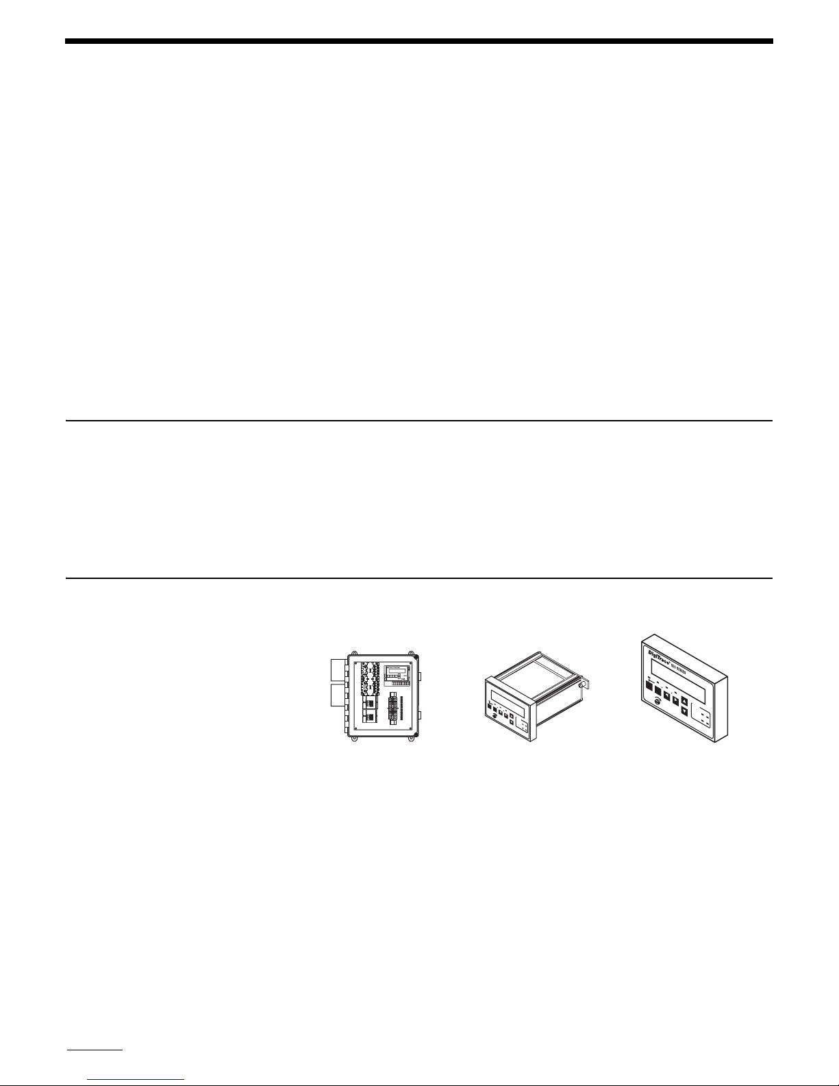
Enclosure assembly Control module(s)
(One for every two circuits)
A
L
S
A
H
R
IF
M
T
M
A
/B
L
O
C
K
O
TRO
INT
LLER
O
N
IT
O
R
C
O
N
F
IG
B
A
C
K
E
N
T
E
S
R
T
ATU
S
A
L
A
R
M
O
U
T
P
U
T
Optional operator
console(s)
Fig. 1.6 920 series control assemblies
Tyco Thermal Controls maintains a shelf stock of enclosure assemblies, control modules, and
consoles. All other enclosure assemblies are built to order. Not all options may be listed. Contact
your local representative for any special applications you may have.
10

1.5.1 ENCLOSURE ASSEMBLY
Enclosure Assemblies
Description Catalog number Part number Weight/lbs
DigiTrace 920 controller–2 Pt in a 14" x 12" x 8" FRP enclosure
with window and quick-release latches, control module, and operator console. 1P 30 A 277 V SSR/pt. Controls two circuits, each
with a 1-pole solid-state relay. (Approved for Class 1, Div. 2 areas)
DigiTrace 920 controller–2 Pt in a 14" x 12" x 8" FRP enclosure
with window and quick-release latches, control module, and operator console. Includes an isolated 2-wire RS-485 communication
option. 1P 30 A 277 V SSR/pt. Controls two circuits, each with a
1-pole solid-state relay. (Approved for Class 1, Div. 2 areas)
DigiTrace 920 controller–2 Pt in a 14" x 12" x 8" FRP enclosure
with window and quick-release latches, control module, and operator console. 2P 30 A 277 V SSR/pt. Controls two circuits, each
with a 2-pole solid-state relay. (Approved for Class 1, Div. 2 areas)
DigiTrace 920 controller–2 Pt in a 14" x 12" x 8" FRP enclosure
with window and quick-release latches, control module, and operator console. Includes an isolated 2-wire RS-485 communication
option. 2P 30 A 277 V SSR/pt. Controls two circuits, each with a
2-pole solid-state relay. (Approved for Class 1, Div. 2, areas)
DigiTrace–DigiTrace Supervisory Software DigiTrace Supervisor 10391-002 1
Note: The NEC (and CEC) rules specify that all ungrounded—i.e., hot—legs of a circuit, must be switched in the event of a ground fault. This means for
207 V single-phase applications, you must specify a 2-pole (2P) version if you are not using external GFI breakers.
920*E4FWL*SIS302*SS3102*HTC*CON 10160-010 27
920*E4FWL*SIS302*SS3102*HTC485*CON 10160-011 27
920*E4FWL*SIS302*SS3202*HTC*CON 10160-012 32
920*E4FWL*SIS302*SS3202*HTC485*CON 10160-013 32
Control Modules
DigiTrace 920 controller–Control module only
(No communications options installed)
DigiTrace 920 controller–Control module with an isolated
2-wire RS-485 communication option installed
DigiTrace 920 controller–Control module with modem
communications option installed
Operator Console
DigiTrace 920 controller–Operator console 920CON 10260-005 1
920HTC 10260-001 1
920HTC*485 10260-004 1
920HTC*MDM 10260-002 1
Contact your local representative for other available configurations that are not listed above.
11

Section 2 Installation and Wiring
2.1 Introduction
Caution: Be sure all personnel involved in installation, servicing, and programming are qualified
and familiar with electrical equipment, their ratings and proper practices and codes. Multiple
voltages and signal levels may be present during the installation, operation, and servicing of this
product. Do not power the product until the safety provisions outlined in this section have been
observed.
This section includes information on the initial inspection, preparation for use, and storage
instructions for the 920 series heat trace controller.
2.2 Initial Inspection
2.3 Operator Safety Considerations
Caution: Solid-state relay (
removed. Exercise care when handling
Inspect the shipping container for damage. If the shipping container or cushioning material is
damaged, it should be kept until the contents of the shipment have been verified for completeness and the equipment has been checked mechanically and electrically. Procedures for configuring and operating the heat trace controller are given in Section 3 on page 18. If the shipment is
incomplete there is mechanical damage, a defect, or the controller does not pass the electrical
performance tests, notify your Tyco Thermal Controls representative. If the shipping container is
damaged, or the cushioning material shows signs of stress, notify the carrier as well as your
Tyco Thermal Controls representative. Keep the shipping materials for the carrier’s inspection.
The standard 920 controller using solid-state relays is suitable for Class I, Division 2, Groups A,
B, C, D and Zone 2 hazardous areas. Hazardous areas are defined by Article 500 of the National
Electrical Code and Section 18 of the Canadian Electrical Code. Contactor-based assemblies are
suitable for use in ordinary (non-hazardous) areas only.
Caution: Many wiring configurations will use more than one power source and all must be deenergized prior to performing any maintenance on a controller circuit.
SSR) modules may be extremely hot immediately after power is
SSRs.
2.4 Operating Environment
2.5 Installation Location
12
The operating environment should be within the limitations described in the 920 heat trace controller specifications outlined in Appendix A on page 61.
The wide ambient operating temperature range of the controller permits installation in any convenient location. Considerations should include expected atmospheric conditions, accessibility
for maintenance and testing, the location of existing conduits, and hazardous area rating. Ambient temperature conditions may affect load current ratings.
Caution: Always be sure that the intended location is classified as an area that the product is
approved for as defined by Article 500 of the National Electrical Code and/or Part I, Section 18 of
the Canadian Electrical Code.
2.6 Mounting Procedures
Mounting hole dimensions for the standard enclosures are shown in Appendix B on page 63. If
possible, conduit entries should be made in the bottom of the enclosure to reduce the possibility
of water entry or leakage. Conduit entries must be drilled/punched following the enclosure manufacturer’s recommendations. Use bushings suitable for the enclosure type and install such that
the completed installation remains waterproof. Grounding hubs and conductors must be
installed in accordance with Article 501-4(b) of the National Electrical Code and Part I of the
Canadian Electrical Code.
The user may want to consider enclosure drain holes in applications where moisture is a problem; drill 0.125" holes in the bottom of the enclosure on both the left and right sides. Two holes
reduce the possibility that one will plug and ensures drainage if the enclosure is not perfectly
level. Note that drilling holes in the enclosure compromises the NEMA 4 rating. Controllers
should be removed from the enclosure before any holes are drilled or cut to prevent damage due
to flying debris.
2.6.1 CONTROL MODULE INSTALLATION AND REMOVAL
Caution: Always ensure that the power to the unit is turned off during installation or removal to
avoid the risk of injury and damage to the controllers.
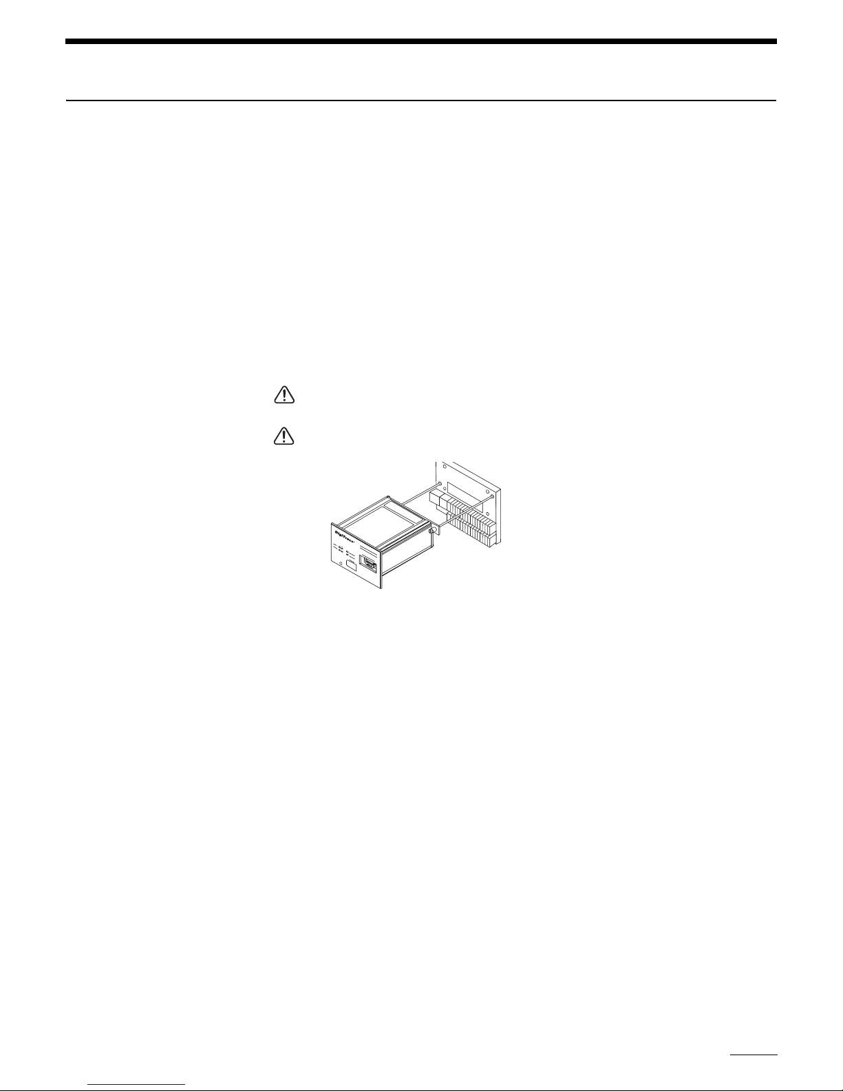
Warning—Explosion Hazard! Do not install or remove the control module while the unit is
powered.
Fig 2.1 Control module installation
The 920 series controller is designed to be mounted to a flat back plate/panel using a terminal
board. This plug-in design simplifies installation and maintenance by allowing all of the lowvoltage field wiring to remain undisturbed while a control module is installed or removed.
Installation of the control module is easily accomplished by plugging it into the connector on the
terminal board.
• The module is fully inserted once its rear cover is flush to the top surface of the terminal
board. The connectors are designed to be self-aligning, so no undue force should be
required.
• Next, secure the module using the two captive screws provided (one located on each side of
the rear cover). These should thread easily into the terminal board. Be sure to align the
screws properly to avoid cross-threading them.
To remove the control module, loosen the two captive screws. Once they have been completely
loosened, they will float freely in their respective retaining collars without falling out. The module
may now simply be pulled straight out of its connection.
2.6.2 OPERATOR CONSOLE INSTALLATION AND REMOVAL
The operator console is designed to be easily installed or removed while the controller is powered—even in Class I Division 2 and Zone 2 hazardous areas. It may be temporarily or permanently installed.
The console is installed in three steps:
13
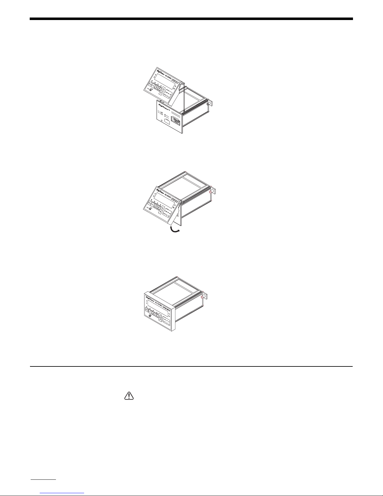
Step 1 “Hook” the lip provided on the rear cover of the console over the top edge of the con-
trol module front plate.
Fig. 2.2 Console installation – Step 1
Step 2 “Hinge” the bottom of the console downwards until it is flush with the front of the con-
trol module.
2.7 Wiring
Fig. 2.3 Console installation – Step 2
Step 3 If the console is to be permanently installed, secure it to the control module using the
captive screw provided. It should be finger tight only. Do not over-tighten the screw or damage
to the console housing may occur.
Fig. 2.4 Console installation – Step 3
To remove the console, follow the three steps outlined above in reverse order.
Wiring diagrams for typical configurations are included in Appendix C on page 68.
Caution: Always verify wiring connections before applying power to the controller or connected
circuits. To avoid injury or equipment damage, do not install or remove wiring while controller
power is on.
14
To minimize the chance of loose connections, the terminal board uses lever-operated, springloaded terminals. See Appendix A on page 61 for allowable wire sizes and recommended insulation strip lengths.
2.7.1 TEMPERATURE SENSOR CONNECTIONS
Use shielded, twisted, three-conductor wire for the extension of
RTD leads. The wire size should
ensure that the maximum allowable lead resistance is not exceeded. Shields on
should be grounded at the controller end only, using the terminals provided.
Temperature Sensors Terminal No.
Point A – Shield 25
Point A TS 1 Source (
Point A TS 1 Sense (
Point A TS 1 Common (RED)28
Point A – Shield 9
Point A TS 2 Source (
Point A TS 2 Sense (WHT)11
Point A TS 2 Common (
Point B – Shield 29
Point B TS 1 Source (
Point B TS 1 Sense (
Point B TS 1 Common (
Point B – Shield 13
Point B TS 2 Source (
Point B TS 2 Sense (
Point B TS 2 Common (
WHT)26
WHT) 27
WHT)10
RED)12
WHT)30
WHT)31
RED)32
WHT)14
WHT)15
RED)16
RTD wiring
Note: Some
RTDs may be constructed with the Sense wire color-coded as Black.
2.7.2 ALARM RELAY CONNECTIONS
The alarm output relay is a programmable dry contact output. It may be programmed for N.O.,
N.C., steady or flashing operation, and is typically used to annunciate an alarm to an external
device such as a DCS, PLC, etc.
Note: The alarm relay is intended to be used for switching low-voltage, low-current signals. Do
not use this relay to directly switch line voltages. Ensure that your application stays within the
ratings of the relay contacts as defined in Appendix A on page 61.
The alarm relay may also be used in conjunction with the +9 Vdc source to switch an external,
line-voltage relay to drive a local pilot light, etc. Refer to the wiring diagrams in Appendix C on
page 68 for example connection details.
Alarm and Control Signals Terminal No.
Alarm relay dry contact output 17
Alarm relay dry contact output 18
Ground 19
+9 Vdc nominal Out (100 mAmps maximum) 1
Common 2
Common 3
2.7.3 EXTERNAL INPUT/OUTPUT
These input and output terminals are used to implement the Override and Ambient Temperature
Control Mode features. Refer to Section 3 on page 18 for programming details, and Appendix C
on page 68 for example wiring diagrams.
15

Miscellaneous Signals Terminal No.
External input (+) 20
External input (-) 21
External output (+) 4
External output(-) 5
2.7.4 COMMUNICATION SIGNAL CONNECTIONS
The communications terminal assignments change based on the type of option installed. If
present in a control module, the type of communications interface will be identified by a label
located next to the module’s rating label.
Communications wiring should use twisted conductor, shielded cable. Shields on communications wiring should be grounded at one end only, using the terminals provided.
The following tables define the appropriate signal connections for the various types of interfaces:
RS-485 (2-Wire) Connections
Communication Signal Terminal No.
Receive/transmit data (+) 6
Receive/transmit data (-) 22
Shield 8
Shield 24
RS-232 Connections
Communication Signal Terminal No.
Receive data 6
Data carrier detect 7
Clear to send 8
Transmit data 22
Request to send 23
Common 24
Modem Interface Connections (Note that these particular signals are not polarity sensitive)
Communication Signal Terminal No.
Modem 6
Modem 22
Shield 8
Shield 24
2.7.5 POWER CONNECTIONS
All of the power terminals are numbered for easy identification. Do not attempt to use wire sizes
that exceed the marked terminal ratings and avoid terminating two wires on the same terminal
whenever possible.
Always be sure that all terminals are adequately tightened according to the terminal manufacturer’s specification. See Appendix A on page 61 for allowable wire sizes, recommended insulation strip lengths, and tightening torque. A loose terminal can cause arcing and damage to the
terminal or incorrect operation of the controller.
16
Note: Make sure that power terminals are re-tightened several days after installation. Stranded
wire will tend to compress when initially installed; therefore, these terminals should be checked
for tightness several times after the system is installed to ensure that a good connection is main-

tained. Be certain to use the proper size screwdriver for the terminal blocks to minimize the
chance of damage to the terminals.
If the controllers are installed in either a metallic or non-metallic enclosure, follow the enclosure
manufacturer’s recommendations for proper grounding. Do not rely on conduit connections to
provide a suitable ground.
Grounding terminals/screws are provided for connection of system ground leads. Proper system
grounding is required for safe and correct operation of the controller’s protection features.
2.7.6 INPUT POWER
The 920 controller may be powered directly from the trace voltage (120 Vac to 277 Vac),
through a step-down transformer, or from a separate circuit. The same wiring terminal assignments are used in all configurations, as defined below:
Power Connections Terminal No.
Line/L1 power input 1
Line/L1 Control Power Input 2
Neutral/L2 Power Input 3
Neutral/L2 Control Power Input 4
L3 Power Input (3Ph only) 5
Line/L1 Output to Trace 6
Neutral/L2 Output to Trace 7
L3 Output to Trace (3Ph only) 8
Note that terminals 5 and 8 are only used for implementing 3-phase switching (this is true for
both SSR and contactor configurations).
When powering the controller directly from the incoming trace power (120 Vac to 277 Vac),
jumpers are installed between terminals 1 and 2 and 3 and 4. This is the standard factory configuration. When the controller is to be powered from another voltage source, the jumpers between
terminals 1 and 2 and 3 and 4 should be removed, and the controller power connected to terminals 2 and 4.
In applications where a neutral-based 4-wire 3-phase source is available, the controller may be
powered from one line to neutral connection, while the trace is operated from the line-to-line
connection, eliminating the need for step-down transformers or separate power sources. This
can be accomplished by removing the jumper between terminals 3 and 4 only. Controller power
can then be derived from the L1 trace power on terminals 1 and 2 and the incoming neutral connection for controller power would be connected to terminal 4.
Wiring diagrams for typical 1- and 2-pole configurations are included in Appendix C on page 68.
Note: The contactor version Switch Interface modules provide a switched line voltage signal to
drive the contactor coil. This is derived from the control power and, as such, requires that the
contactor coil voltage be specified to match the control voltage present on terminals 2 and 4.
Caution: Many wiring configurations will use more than one power source and all must be deenergized prior to performing any maintenance on a controller circuit. When servicing one control point, remember that power may also be present on the second control point.
2.8 Initial Power-up
Caution: Before applying power to the controller, ensure that powering the circuit will not damage it if power limiting or the setpoint temperature have not been set correctly. If there is any
doubt, the load should be disconnected until the 920 has been suitably programmed for correct
and safe operation.
17

2.9 Setup for the 920
2.8.1 INITIAL CABLE TEST
To minimize the risk of damage to the controller due to a cable fault, the integrity of the heating
cable should be verified by:
1. Using a megger to perform a high-voltage insulation test
2. Using an ohmmeter to ensure that the heating cable is not shorted
These tests must be performed with the controller output disconnected. Once the cable has been
checked, it may be reconnected to the controller and power applied.
2.8.2 RANDOM START DELAY
All 920 series control modules incorporate a
RANDOM START-UP DELAY feature, ensuring that all
units do not power on at the same time. When power is first applied to a controller, it will hold its
output off for a random time (0 to 9 seconds), equal to the last digit of the
HTCBUS™ communi-
cations address (see section 3.9.2 on page 43). Once the start-up delay has timed out, the controller will begin normal operation.
The 920 may be programmed using the optional 920 Operator Console, or a Group Communications Controller (
GCC) if the modem communications option is installed. For instructions on the
operation of these devices, refer to the corresponding operating manuals. For complete instructions on programming the 920, see the Section 3 on page 18.
2.9.1 VOLTAGE READING SETUP
The 920 series control module is tested, calibrated, and ordered separately from the switch
interface modules which contain the voltage sensing circuitry. This prevents Tyco Thermal
Controls from calibrating the control modules to specific switch interfaces and removing any
component inaccuracies. Generally, the voltage readings will be within 3 Vac to 5 Vac when
shipped from Tyco Thermal Controls. If more accurate voltage readings are desired, they may be
adjusted as part of the initial setup of the controller. This requires measurement of the trace voltage using a multimeter and adjusting the
VOLTAGE TURNS RATIO setting to arrive at more accu-
rate voltage readings. See section 3.5.21 on page 26.
2.9.2 SWITCH RATING SETUP (SSR ONLY)
The 920 series control module is ordered and shipped as a separate item from the enclosure
assembly. This prevents Tyco Thermal Controls from predetermining the
settings since various types of output switches are available.
RATING
The user should verify that the switch current ratings are set properly for the rating of the solidstate relays that are included as part of the enclosure assembly. Refer to section 3.5.7 on
page 22 for more information on the
default setting is defined in Appendix F on page 76.
Section 3 Programming and Configuration
3.1 Introduction
This section provides complete operating and setup instructions for the 920 Series Heat-Tracing
Controller. The text describes each available function in detail, its purpose, valid range settings,
the procedure for use, and some operational tips and suggestions.
While configuring the controller, it is important to remember that the 920 series controller is a
two control point device. Both control points allow completely independent operation and, as
such, have their own individual settings that must be configured. Throughout the text, the first
control point is referred to “Point A” and the second as “Point B.”
SWITCH CURRENT
SWITCH CURRENT RATING setting. Tyco Thermal Controls
18
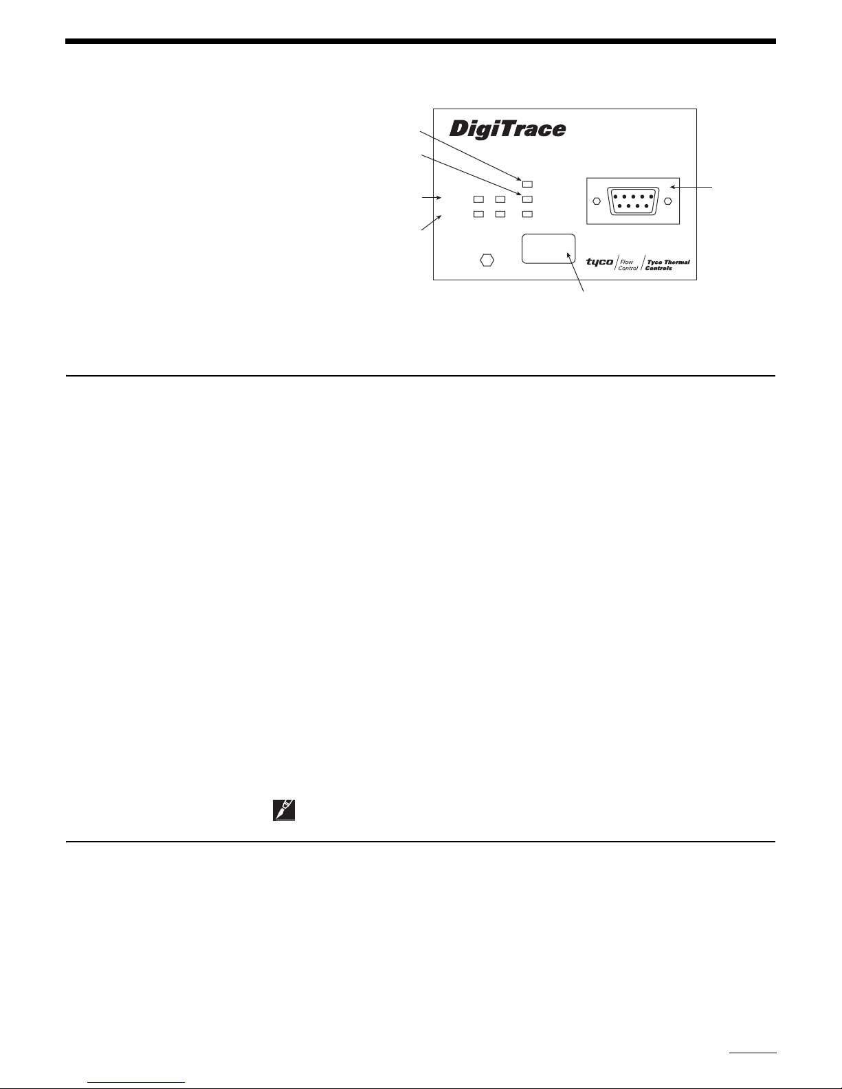
3.2 Front Panel Features
“Power On” LED
Communications status
indicators
Alarm status
indicators
Output status
indicators
Fig 3.1 DigiTrace 920 front panel
ALARM
OUTPUT
920 SERIES
AB
POWER
TRANSMIT
RECEIVE
ADDRESS
A - 20910
B - 20911
PROGRAMMABLE DUAL POINT
HEAT TRACING CONTROLLER
CONSOLE INTERFACE
Communications addresses
for Control Point A and
Control Point B
Operator
console
connection
Front panel features of the heat trace controller are shown in Figure 3.1. The remainder of this
Section describes the front panel status and display
LEDs.
3.2.1 920 FRONT PANEL DISPLAY
The basic 920 series control module front panel includes seven
LED indicators. Four of these are
used to indicate the “Output” and “Alarm” status of control points A and B.
Status LEDs
OUTPUT The OUTPUT LED, when illuminated steadily, indicates that the output of the controller is
turned on and is allowing current to flow in the trace circuit. For
SSR versions, a flashing LED
indicates that the controller is pulsing its output on and off to maintain the setpoint temperature
and/or control the average amount of current/power the tracer uses. A separate
LED is provided
for Point A and Point B.
ALARM The ALARM LEDs will flash (approximately once per second) when the controller has
detected an alarm condition. A separate
LED is provided for Point A and Point B.
TRANSMIT The TRANSMIT LED (“Tx”) flashes when the controller is sending information over its
communications port to another device. This
LED is only used when an optional communications
interface is installed.
RECEIVE The “RECEIVE” LED (“Rx”) flashes when the controller is receiving information over its
communications port from another device. This
LED is only used when an optional communica-
tions interface is installed.
POWER Indicates the module is powered on.
3.3 920 Operator Console Display
Note: Older versions of the controller may not have this LED.
The optional 920 Operator Console provides a menu-driven, alphanumeric interface to ease configuration and troubleshooting. The following features are part of the controller’s programming,
but are only used in conjunction with the 920 Operator Console. For a detailed description of
each of the console features and operating instructions, refer to the separate DigiTrace 920
Series HTC Operator Console—Installation and Operating Instructions (Tyco Thermal Controls
reference H56903).
19

3.4 920 Functions
The sections that follow explain the various functions of the 920 controller and how they can be
accessed. The first line of each section identifies the function to be described. Each section goes
on to explain the Purpose of the function, the Range over which it may be set, the Procedure for
setting or enabling the feature, and finally any Notes or Cautions that pertain to the particular
function.
Setting and using the alarming functions of the 920 controller is a two step procedure:
1. The alarm must be enabled or disabled accordingly. When using the 920 Operator Console,
access to all alarming functions is available using the
CONFIGURE mode sub-menus. When
using the Model 780/GCC-9000 Group Communications Controller, the alarm masks may be
found in the
HTC SETUP Section. Please see the appropriate operating manual for instructions
on accessing these parameters.
2. The corresponding alarm point value may be modified appropriately for the application.
When using the 920 Operator Console, access to the alarm points is also available using the
CONFIGURE mode sub-menus. Modification of the alarm setpoint values is found in the HTC
SETPOINTS
Section of the Model 780/GCC-9000 Group Communications Controller. Please
see the appropriate operating manual for instructions on accessing this feature.
Note: The 920 Operator Console or the Model 780/GCC-9000 will not allow modification of an
alarm point value if the alarm has been disabled (
temperature settings. These may still be modified if the corresponding
been enabled (
ENA).
DIS) with the exception of the HIGH TS ALARM
HIGH LIMIT CUTOUT has
3.5 Control Point Setup
This Section describes the setup parameters that relate to a specific control point—either Point
A or Point B. These parameters must be configured for each of the two control points that are
used.
3.5.1 CONTROL SETPOINT TEMPERATURE
Purpose: The
maintains the circuit temperature through either proportional, proportional ambient
CONTROL SETPOINT temperature is the value at which the heat trace controller
SSR, propor-
tional ambient contactor, or deadband control, depending on the controllers’ configuration. The
CONTROL SETPOINT temperature is compared to the temperature measured by the control tem-
perature sensor (
TS). A decision is then made to turn on or turn off the output to control power
to the tracer.
Range: –76°F to 1058°F (–60°C to 570°C)
Procedure: Adjust the
ture. The
HTC will switch the output ON and OFF in an attempt to maintain this temperature.
CONTROL SETPOINT temperature value to the desired maintain tempera-
Notes:
• See section 5.2 on page 50 of this manual for an explanation of Proportional, Proportional
Ambient
• When using an optional 920 Operator Console (for V3.11 and up) the
temperature range may be limited to the
SSR, Proportional Ambient Contactor and Deadband Control algorithms.
CONTROL SETPOINT
CONSOLE SETPOINT MAXIMUM and MINIMUM values
(see sections 3.5.29 on page 29 and 3.5.30 on page 29). This is a safety feature to prevent
users in the field from modifying the
CONTROL SETPOINT temperature setting to a dangerous
level.
20
3.5.2 ALPHANUMERIC TAG ASSIGNMENT
Purpose: A 19-character alphanumeric
TAG may be assigned to a control point to allow it to be
easily associated with a pipe, vessel, process, circuit, drawing name or number.
Setting: Any combination of 19 characters from A-Z, 0-9, /, -, ., (,) or #.

Procedure: Using the 920 Operator Console, enter the desired text. Refer to the separate
DigiTrace 920 Series HTC Operator Console—Installation and Operating Instructions (Tyco
Thermal Controls reference H56903) for
TAG entry information.
3.5.3 SWITCH CONTROL MODE
Purpose: This allows selection of the type of algorithm to be used by the
CONTROL SETPOINT temperature. There are four different control algorithms available in the
HTC—proportional, proportional ambient SSR, proportional ambient contactor, and deadband.
HTC to maintain the
See section 5.2 on page 50 for a complete explanation of these controlling techniques as implemented in the HTC.
Setting:
TACTOR
PROPORTIONAL, PROPORTIONAL AMBIENT SSR (V3.11+), PROPORTIONAL AMBIENT CON-
(V3.11+), or DEADBAND
Procedure: Select the desired control technique. Note that deadband control and proportional
ambient contactor should be selected when using contactors or when precise control and
advanced current handling functions are not required.
Note: If deadband is selected, a
menu, else a
RENT RATING
PROPORTIONAL BAND setting will be available. No MAXIMUM POWER, SWITCH CUR-
or CIRCUIT BREAKER CURRENT RATING settings are available when the controller is
set to operate in either contactor mode. If proportional ambient contactor is selected, the
setting will also be available.
TIME
DEADBAND setting will be available in the HTC configuration
CYCLE
3.5.4 PROPORTIONAL BAND SETTING
(For use with the three proportional control modes only)
Purpose: When an
proportional ambient
HTC equipped with SSRs is used to control a heating circuit, proportional or
SSR modes are normally used, allowing for more precise temperature con-
trol. When using contactors, the proportional ambient contactor mode should be selected.
This programmable proportional band acts to vary the on to off time of the output based on the
difference between the measured control temperature and the desired
CONTROL SETPOINT
temperature.
Range: 2°F to 90°F (1°C to 50°C)
2°F to 630°F (1°C to 350°C) V3.2x and up
Procedure: Adjust the
SETPOINT
temperature.
PROPORTIONAL BAND setting to the desired differential from the CONTROL
Notes:
• See section 5.2 on page 50 for an explanation of how the three proportional modes use the
PROPORTIONAL BAND setting.
• When using series-type, constant wattage, or self-regulating tracers in an ambient temperature control application, significant energy savings may be realized by setting the
TIONAL BAND
to match the expected range of operating ambient temperatures. Tracer design
PROPOR-
is normally done assuming worst-case conditions, where 100% of the design output power
is required to maintain the desired minimum temperature. When the ambient temperature is
above the design minimum but some heat is still required, adjusting the
PROPORTIONAL BAND
width accordingly will allow only the amount of power required by the application to be consumed, while maintaining the minimum required temperature.
Example: A water line must be protected from freezing when the ambient temperature falls
below 10°C. Either the proportional ambient
SSR or proportional ambient contactor mode is
selected as the control method (depending on the type of switch being used). The heater and
insulation are chosen to impart enough heat to the line to keep it from freezing at a worst-case
ambient temperature of –40°C. At 10°C, the heater should be completely off, since no heat is
required at this temperature to guarantee that the product will not freeze. It follows that the
amount of heat required by the water line decreases as the ambient temperature increases from
–40°C to 10°C (theoretically, at –15°C the heater output should be approximately 50%). Setting
21

the CONTROL SETPOINT temperature to 10°C, and the PROPORTIONAL BAND to 50°C, will force the
controller’s output to be 100% on at –40°C, 50% on at –15°C, and off at 10°C.
3.5.5 DEADBAND SETTING
(Deadband control mode only or if a point controls an
INHIBIT output signal)
Purpose: When an
HTC equipped with a contactor is used to control a trace circuit, it is neces-
sary to use deadband rather than proportional control. This is done to prevent the contactor
from switching on and off rapidly and being worn out prematurely. This deadband acts as an on/
off control where the decision to turn the output off or on is based upon a window of difference
between the measured control temperature and the desired
CONTROL SETPOINT temperature.
Range: 2°F to 90°F (1°C to 50°C)
Procedure: Adjust the DEADBAND setting to the desired differential from the desired CONTROL
SETPOINT
temperature. When the control temperature is above the setpoint + deadband value,
the controller will turn off the output to the tracer. If the control temperature drops down below
the setpoint, the output will be turned back on. Note that the smaller the DEADBAND setting, the
more often the contactor will cycle on and off, decreasing its operational life.
Notes:
• See section 5.2 on page 50 for an explanation of deadband control. Note that the
, SWITCH CURRENT RATING, and CIRCUIT BREAKER CURRENT RATING settings are not
POWER
available when the
• The
DEADBAND parameter is also available for Point A when the EXTERNAL OUTPUT is config-
ured for use as an
HTC is set to deadband mode (typically when switching a contactor).
INHIBIT output. See section 3.6.4 on page 30 for additional details.
MAXIMUM
3.5.6 CYCLE TIME SETTING (V3.11 AND UP)
(For proportional ambient contactor control mode only)
Purpose: This parameter determines the minimum amount of time it will take for a complete
contactor
ON-OFF-ON cycle.
Range: 10 to 255 minutes
Procedure: Adjust the
CYCLE TIME setting to yield the desired contactor ON+OFF time for a partic-
ular duty cycle. For instance, if the contactor should remain on for five minutes with a 50% duty
cycle, then the
temperature,
CYCLE TIME should be 10 minutes. A new duty cycle (based on measured control
PROPORTIONAL BAND and CONTROL SETPOINT) is calculated every time the contac-
tor is required to change state.
Notes:
• If the calculated duty cycle is 0% or 100%, then the contactor will not change state and the
duty cycle will not be calculated again for a time period =
CYCLE TIME/30.
• The minimum cycle time setting is 10 minutes, and the minimum controller output duty cycle
is 3%. This results in a minimum contactor
ON time of 18 seconds.
3.5.7 SWITCH CURRENT RATING SETTING (SSR ONLY)
Purpose: The
SWITCH CURRENT RATING setting defines the current rating of the output switch. It
is used by the controller to limit the maximum average current that will be allowed to flow to the
load before it begins to adjust the output duty cycle, limiting the amount of current to an acceptable level.
Range: 0.3 to 100.0 amps
(
CURRENT TURNS RATIO = 1.00)
Procedure: Adjust the SWITCH CURRENT RATING setting to match the current rating of the output
device (i.e. 30.0 amps). Note that the
CURRENT TURNS RATIO setting. The absolute maximum adjusted SWITCH CURRENT RATING setting
is 300.0 amps. The absolute minimum adjusted
See section 3.5.22 on page 26 for more information regarding the
SWITCH CURRENT RATING setting is affected by the
SWITCH CURRENT RATING setting is 0.1 amps.
CURRENT TURNS RATIO
function.
22

3.5.8 CIRCUIT BREAKER CURRENT RATING SETTING (SSR ONLY)
Purpose: The
tripping of the circuit breaker immediately upstream of the controller. The
square of the current related to time (I
CIRCUIT BREAKER CURRENT RATING setting helps prevent in-rush induced nuisance
2
T) and adjusts the output duty cycle accordingly, limiting
HTC evaluates the
the amount of current to an acceptable level.
Range: 0.3 to 100.0 amps
(
CURRENT TURNS RATIO = 1.00)
Procedure: Adjust the CIRCUIT BREAKER CURRENT RATING setting to the heating circuit breaker
size (i.e. 30.0 amps). Note that the
CURRENT TURNS RATIO setting. The absolute maximum adjusted CIRCUIT BREAKER CURRENT RAT-
setting is 300.0 amps. The absolute minimum adjusted CIRCUIT BREAKER CURRENT RATING
ING
setting is 0.1 amps. See section 3.5.22 on page 26 for more information regarding the
TURNS RATIO
function.
CIRCUIT BREAKER CURRENT RATING setting is affected by the
CURRENT
Note: This feature should not be used to reduce the size of a circuit breaker or increase the max-
imum heating cable length. It can be quite effective in preventing nuisance trips due to incorrect
design or factors outside those considered by the design.
3.5.9 MAXIMUM POWER SETTING (SSR ONLY)
Purpose: This user-selectable level limits the maximum amount of power applied to a heat trace
circuit. This is an average power calculated by the controller using the average current and
applied voltage. The
appropriate level. The
HTC switches the output on and off rapidly to limit the average current to an
MAXIMUM POWER level may be adjusted to eliminate step-down transform-
ers, lower the effective output wattage of a cable, or implement energy management of the heat
trace circuit.
Range: 3 to 33,000 Watts
(
VOLTAGE and CURRENT TURNS RATIOS = 1.00)
Procedure: Adjust the MAXIMUM POWER level to the desired value (watts). Use the TEST TRACING
function to observe the power limiting operation.
Notes:
• This function may be set within reasonable limits for the particular tracer being powered. The
effective resolution of the setting is limited to 1/30th of the calculated full on power.
• Do not set the
MAXIMUM POWER below full output for applications that do not require control
of power.
• This feature is affected by the
VOLTAGE and CURRENT TURNS RATIO settings. The maximum
range using adjusted values of voltage and current is 65,535 watts. See sections 3.5.21 on
page 26 and 3.5.22 on page 26 for more information regarding the turns ratio functions.
3.5.10 3-PHASE POWER CALCULATION (V3.11 AND UP)
Purpose: This parameter selects the type of power calculation that the HTC is to perform.
Setting:
NO or YES
Procedure: If an automatic 3-phase power calculation is desired, select YES. If a normal power
calculation is desired, select
NO.
Note: For the total 3-phase power calculation to be accurate the following conditions must be
met:
• All three phases must be balanced and star (“Y”) connected
• The measured corrected current is one of the phase currents
• The measured corrected voltage is the line to line voltage
The formula used to calculate this total power is: P
total
= √3 x I
phase
3.5.11 TS FAIL MODE (V3.11 AND UP)
Purpose: This parameter determines whether the
HTC turns the output switch ON or OFF if all
selected temperature sensors fail to provide a control temperature.
x V
line-line
23

Setting: OFF or ON
Procedure: If the HTC should turn the output switch off when it cannot read a valid control tem-
perature, then select
OFF; otherwise, if the output switch should turn on, then select ON.
Note: This parameter is part of the
TS CONTROL MODE.
3.5.12 TEMPERATURE SENSOR CONTROL MODE
Purpose: The
TS CONTROL MODE allows the selection of one of eleven possible temperature con-
trol modes for the controller. The different modes allow redundant fail-safe temperature sensing,
averaging, or minimum maintain temperature control.
Setting: Select one of the following eleven possible modes:
Control TS and Description
CONTROL USING TS 1, FAIL OFF/ON
CONTROL USING TS 1, FAIL TO TS 2
CONTROL USING TS 2, FAIL OFF/ON
CONTROL USING TS 2, FAIL TO TS 1
CONTROL ON AVERAGE, FAIL OFF/ON
CONTROL ON AVERAGE, FAIL TO GOOD
CONTROL ON LOWEST, FAIL OFF/ON
CONTROL ON LOWEST, FAIL TO GOOD
The following are only available in V3.11+:
CONTROL USING EXT. INPUT, FAIL OFF/ON
CONTROL USING EXT. INPUT, FAIL TO TS 1
CONTROL USING EXT. INPUT, FAIL TO TS 2
Where OFF/ON = Controller’s output switch turned OFF or ON as determined by the TS FAIL MODE.
Example: With a TS CONTROL MODE of CONTROL ON AVERAGE, FAIL TO GOOD, the controller will
measure both sensors (
and cycle the heater
TS 1 and TS 2), averaging the two temperature value;, display the results;
ON or OFF to maintain the CONTROL SETPOINT temperature. This is the pri-
mary control mode. If either sensor should fail, the controller will transfer control to the remaining “good” sensor and generate the appropriate
TS 1 or TS 2 FAILURE ALARM (assuming that the
alarm is enabled). The temperature will now be maintained based on this measured value. If the
remaining good sensor fails, the controller will turn the heater
FAIL MODE
setting. The appropriate TS 1 or TS 2 FAILURE ALARM will be also be generated.
OFF or ON as determined by the TS
24
Procedure: Select the control mode that best suits the application.
Notes:
• Ensure that
page 32, and 3.7.10 on page 34 for a complete explanation of
HTC.
• If the selected
set to
TS FAILURE ALARMS are enabled. See sections 3.7.1 on page 32, 3.7.4 on
RTD failure detection in the
TS CONTROL MODE uses the EXTERNAL INPUT then the EXTERNAL INPUT must be
TEMPBUS™ (see Section 3.6.3). Also, the CONTROL TS FAILURE ALARM is non-latching in
this mode.
• Fail safe mode is always disabled if the
TS CONTROL MODE = EXT. INPUT, FAIL OFF/ON.
3.5.13 TS 1 TYPE (V3.11 AND UP)
Purpose: This parameter specifies the type of
RTD that is connected to the HTC’s TS 1 input.
Setting: 3-wire 100 Ω platinum or 2-(or 3-) wire 100 Ω nickel-iron (Ni-Fe)
Procedure: Select the type of RTD that is connected to the TS 1 input.
Note: If a 2-wire 100 Ω nickel-iron (Ni-Fe) RTD is selected then the TS 1 LEAD RESISTANCE must
be entered manually (see section 3.5.14 on page 24).
3.5.14 TS 1 LEAD RESISTANCE (V3.11 AND UP)
(For Ni-Fe
RTDs only)

Purpose: This parameter specifies the lead resistance of a 2-wire nickel-iron RTD connected to
the
HTC’s TS 1 input.
Range: 0 to 20.00 Ω
Procedure: Measure the resistance of one of the nickel-iron
input) and use this value as the TS 1 LEAD RESISTANCE.
TS 1
RTD leads (from the RTD to the HTC’s
3.5.15 TS 1 HIGH LIMIT CUTOUT
Purpose: When enabled, the
temperature and force the controller output off if the
temperature setting. This is a non-latching condition, so once the
HIGH TS 1 ALARM temperature setting, the controller will resume normal operation.
TS 1 HIGH LIMIT CUTOUT feature will override the CONTROL SETPOINT
TS 1 reading exceeds the HIGH TS 1 ALARM
TS 1 reading drops below the
Setting: ENABLE or DISABLE
Procedure: Enable or disable the cutout feature as desired.
Notes:
• The
TS 1 HIGH LIMIT CUTOUT feature overrides an autocycle test. A pending autocycle will be
initiated immediately after the
TS 1 temperature drops below the HIGH TS 1 ALARM tempera-
ture setting.
•If a
TS 1 failure occurs and the TS 1 HIGH LIMIT CUTOUT feature is enabled, the switch output
will latch off regardless of the
• If the
TS 1 HIGH LIMIT CUTOUT feature is enabled, then the HIGH TS 1 ALARM temperature set-
ting can be set, regardless of whether the
TS CONTROL MODE setting or the TS FAIL MODE setting.
HIGH TS 1 ALARM is enabled.
3.5.16 TS 2 TYPE (V3.11 AND UP)
Purpose: This parameter specifies the type of
RTD that is connected to the HTC’s TS 2 input.
Setting: 3-wire 100 Ω platinum or 2- (or 3-) wire 100 Ω nickel-iron (Ni-Fe)
Procedure: Select the type of RTD that is connected to the TS 2 input.
Note: If a 2-wire 100 Ω nickel-iron (Ni-Fe) RTD is selected then the TS 2 LEAD RESISTANCE must
be entered (see section 3.5.17 on page 25).
3.5.17 TS 2 LEAD RESISTANCE (V3.11 AND UP)
(For Ni-Fe
Purpose: This parameter specifies the lead resistance of a 2-wire nickel-iron
the
RTDs only)
RTD connected to
HTC’s TS 2 input.
Range: 0 to 20.00 Ω
Procedure: Measure the resistance of one of the nickel-iron RTD leads (from the RTD to the HTC’s
TS 2 input) and use this value as the TS 2 LEAD RESISTANCE.
3.5.18 TS 2 HIGH LIMIT CUTOUT
Purpose: When enabled, the
temperature and force the controller output off if the
temperature setting. This is a non-latching condition, so once the
HIGH TS 2 ALARM temperature setting, the controller will resume normal operation.
TS 2 HIGH LIMIT CUTOUT feature will override the CONTROL SETPOINT
TS 2 reading exceeds the HIGH TS 2 ALARM
TS 2 reading drops below the
Setting: ENABLE or DISABLE
Procedure: Enable or disable the cutout feature as desired.
Notes:
• The
TS 2 HIGH LIMIT CUTOUT feature overrides an autocycle test. A pending autocycle will be
initiated immediately after the
TS 2 temperature drops below the HIGH TS 2 ALARM tempera-
ture setting.
•If a
TS 2 failure occurs and the TS 2 HIGH LIMIT CUTOUT feature is enabled, the switch output
will latch off regardless of the
TS CONTROL MODE setting or the TS FAIL MODE setting.
25

• If the TS 2 HIGH LIMIT CUTOUT feature is enabled, then the HIGH TS 2 ALARM temperature set-
ting can be set, regardless of whether the
HIGH TS 2 ALARM is enabled.
3.5.19 VOLTAGE SOURCE (V3.11 AND UP)
Purpose: This parameter specifies which voltage source the
HTC should use for its voltage mea-
surements.
Setting:
POINT A or POINT B or FIXED
Procedure: If the HTC is not powered from a dedicated switch interface an alternate voltage
source can be selected. If a fixed constant voltage value is to be used then that
must also be entered (see section 3.5.20 on page 26).
SETTING
FIXED VOLTAGE
Notes:
• If an alternate voltage source is selected, then all voltage alarming features are disabled for
this
HTC and the VOLTAGE TURNS RATIO is not used.
• It is not possible to set both points to use the others’ voltage source.
3.5.20 FIXED VOLTAGE SETTING (V3.11 AND UP)
(Only if
VOLTAGE SOURCE = FIXED)
Purpose: This parameter specifies the voltage value that the HTC should use when the VOLTAGE
SOURCE = FIXED
.
Range: 0 to 1000 Volts
Procedure: Adjust the
FIXED VOLTAGE setting to the desired level.
Note: All voltage alarming features are disabled for this HTC and the VOLTAGE TURNS RATIO is not
used when the
VOLTAGE SOURCE is set to FIXED.
3.5.21 VOLTAGE TURNS RATIO ADJUSTMENT
Purpose: The
VOLTAGE TURNS RATIO adjusts voltage readings for applications where a controller
is switching a load through a step-up or step-down transformer, or is being powered from a
source with a different voltage level than the trace voltage.
Range: 0.10 to 9.90 (TO 1)
Procedure: Adjust the
VOLTAGE TURNS RATIO to equal the ratio of the circuit voltage to the con-
troller input voltage. Compare the indicated voltage to the measured voltage after setting the
turns ratio and adjust until the two readings are as close as possible.
e.g.: Heating Circuit Voltage: 480 Volts
Module Input Voltage: 120 Volts
VOLTAGE TURNS RATIO Setting: 4.00
Notes:
• When the
VOLTAGE TURNS RATIO has been set appropriately, the HTC will calculate the circuit
power using the adjusted current and voltage readings. Voltage alarms also use the adjusted
circuit voltages.
• The
VOLTAGE TURNS RATIO is not used if the selected VOLTAGE SOURCE is not from the dedi-
cated switch interface.
3.5.22 CURRENT TURNS RATIO ADJUSTMENT
Purpose: The
CURRENT TURNS RATIO adjusts current readings for applications where a controller
is monitoring a load through an external step-up or step-down current transformer.
Range: 0.10 to 60.00 (TO 1)
Procedure: Adjust the
CURRENT TURNS RATIO to equal the ratio of the primary to secondary
windings of the external current transformer. Compare the indicated current to the measured
current after setting of the
CURRENT TURNS RATIO and adjust until the two readings are as close
as possible.
26
 Loading...