

Page 1
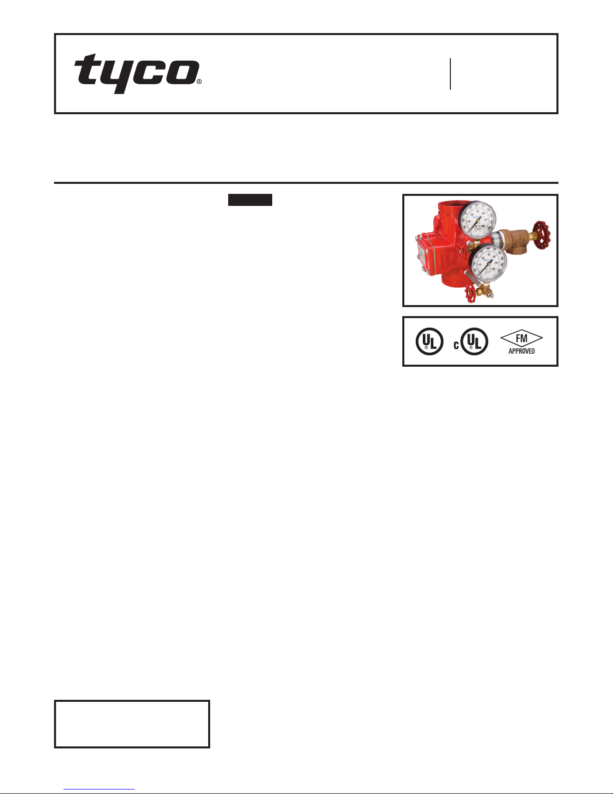
Model CV-1FR Grooved-End
Riser Check Valves
2 Inch to 12 Inch (DN50 to DN300)
Worldwide
Contacts
www.tyco-fire.com
General
Description
The TYCO Model CV-1FR GroovedEnd Riser Check Valve is a compact
and rugged swing-type unit that allows
water flow in one direction and prevents flow in the opposite direction.
A resilient elastomer seal facing on
the spring-loaded clapper ensures a
leak-tight seal and non-sticking operation. The Model CV-1FR Riser Check
Valves are designed to minimize water
hammer caused by flow reversal.
The Model CV-1FR Riser Check Valve
is furnished with grooved ends and
can be installed using GRINNELL
Grooved Couplings or GRINNELL
Figure 71 Flange Adapters. The Model
CV-1FR Riser Check Valves have been
designed with a removable cover for
ease of field maintenance. These valves
can be installed horizontally (with cover
in the upward position) or vertically with
the flow in the upward direction. Refer
to Figure 6.
To facilitate their use in wet-type automatic sprinkler system risers, the
Model CV-1FR Riser Check Valves are
provided with threaded outlets for pressure gauges and a drain connection.
They provide a more compact and economical alternative to an alarm check
valve where a water motor alarm is not
required. Provisions must be made for
a local alarm using an approved flow
switch (not included).
The Model CV-1FR Riser Check Valve
is also Listed for use in conjunction
with the TYCO DV-5 Deluge Valve in
Preaction Systems under air pressure
without the use of prime water.
The Model CV-1FR Riser Check Valves
are a redesign for the Central Figure
590FR and GRINNELL Figure 590FR.
NOTICE
The Model CV-1FR Riser Check Valve
described herein must be installed
and maintained in compliance with
this document and with the applicable
standards of the NATIONAL FIRE PROTECTION ASSOCIATION, in addition to
the standards of any authorities having
jurisdiction. Failure to do so may impair
the performance of this device.
Never remove any piping component
nor correct or modify any piping deficiencies without first de-pressurizing
and draining the system. Failure to do
so may result in serious personal injury,
property damage, and/or impaired
device performance.
The owner is responsible for maintaining their fire protection system and
devices in proper operating condition.
Contact the installing contractor or
manufacturer with any questions.
Technical
Data
Approvals
UL, C-UL Listed
FM Approved
Sizes
2 in. to 12 in. (DN50 to DN300)
Maximum Working Pressure
300 psi (20,7 bar)
Valve Assembly Finish
Red, non-lead paint
Installation
The Model CV-1FR Riser Check Valves
are to be installed in accordance with
this section:
1. The arrow cast on the Body must
point in the direction of the flow.
2. Valves installed vertically must
be positioned with the flow in the
upward direction.
3. Valves installed horizontally must be
positioned with the Cover facing up.
Refer to Figure 6.
4. Grooved-end pipe couplings used
with the Model CV-1FR Riser Check
Valve must be installed in accordance
with manufacturer’s instructions.
NOTE: Valves should be installed a
reasonable distance downstream from
pumps, elbows, expanders, reducers,
or other similar devices to extend the
valve life. Standard piping practices
call for a minimum of five times the pipe
diameter for general use.
Refer to Technical Data Sheet
TFP2300 for warnings pertaining to
regulatory and health information.
IMPORTANT
Page 1 of 4 AUGUST 2018 TFP950
Page 2
TFP950
Page 2 of 6
1/4"
NPT
O.D.
BA
1/4"
NPT
C
D
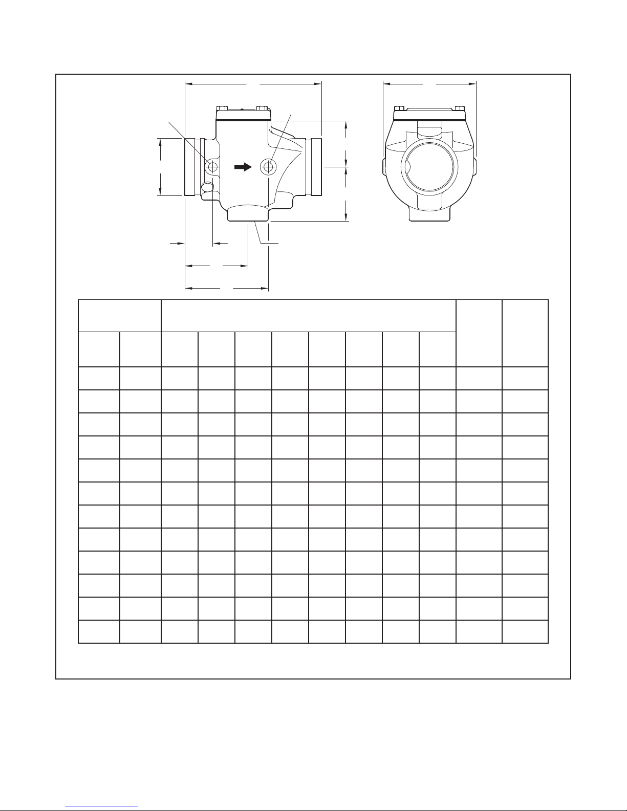
Nominal Pipe Size
ANSI
Inches
DN
2
DN50
2-1/ 2
DN65
76 ,1
DN65
3
DN80
4
DN10 0
139.7
DN125
5
DN125
16 5 .1
DN15 0
6
DN15 0
8
DN200
10
DN250
12
DN300
O.D.
Inches
(mm)
2.375
(60,3)
2.875
(73,0)
-
(76 ,1)
3.500
(88,9)
4.500
(114, 3 )
-
(139,7)
5.563
(141,3)
-
(165,1)
6.625
(168 ,3)
8.625
(219,1)
10.750
(27 3 ,1)
12.75 0
(323,9)
J
E
F
A B C D E F J
6.75
(171, 5)
8.00
(203,2)
8.00
(203,2)
8.37
(212,6)
9.63
(245,6)
10.50
(266,7)
10.50
(266,7)
11. 5 0
(292,1)
11. 5 0
(292,1)
14.00
(355,6)
18.00
(457,2)
21.0
(533,4)
4.38
(111,3)
5.38
(136 ,7 )
5.38
(136 ,7 )
5.72
(145, 3)
6.68
(169,7)
7.40
(188 ,0 )
7.40
(188 ,0 )
8.00
(203,2)
8.00
(203,2)
10 .14
(257, 6 )
12.38
(314, 5)
14. 28
(362,7)
1.9 6
(49,8)
2.63
(66,8)
2.63
(66,8)
2.81
(71,4)
3.80
(96,5)
4.46
(113,2)
4.46
(113,2)
4.62
(117, 4)
4.62
(117, 4)
6.67
(169,4)
8.62
(218,9)
9.93
(252,2)
K
Nominal Dimensions
Inches
(mm)
2.57
(65,3)
3.09
(78,5)
3.09
(78,5)
3.31
(84,1)
3.63
(92,2)
4.1 3
(104,9)
4.1 3
(104,9)
4.50
(114,3)
4.50
(114,3)
5.52
(140,2)
6. 41
(162,8)
7. 27
(184,7)
3.25
(82,3)
3.87
(98,3)
3.87
(98,3)
3.87
(98,3)
4.53
(115,4)
4.90
(124,5)
4.90
(124,5)
5.00
(12 7, 0 )
5.00
(12 7, 0 )
5.46
(138 ,7 )
7.5 0
(190,5)
7.62
(193, 5)
4.37
(111,0)
5.12
(130 ,0 )
5.12
(130 ,0 )
5.12
(130 ,0 )
5.78
(146, 8)
7.0 0
(177, 8 )
7.0 0
(177, 8 )
7. 2 5
(184 ,2)
7. 2 5
(184 ,2)
10.50
(266,7)
10.75
(27 3 ,1)
10.0 0
(254,0)
FIGURE 1
MODEL CV-1FR RISER CHECK VALVES
NOMINAL DIMENSIONS
1.5 6
(39,6)
1.73
(43,9)
1.72
(43,7)
1.72
(43,7)
2.12
(53,8)
2.09
(53,1 )
2.09
(53,1 )
2.00
(50,8)
2.00
(50,8)
2.43
(61,7)
3.38
(85,9)
3.13
(79,5)
K
Inches
NPT
1
1-1/4
1-1/4
1-1/4
2
2
2
2
2
2
2
2
Cover
Bolt
Torque
ft-lb
(Nm)
18
(25)
39
(54)
39
(54)
39
(54)
50
(69)
39
(54)
39
(54)
60
(82)
60
(82)
120
(164)
130
(178)
130
(178)
Approx.
Weight
lb
(kg)
9.0
(4,5)
10.0
(4,5)
10.0
(4,5)
11. 0
(5,0)
25.0
(11,3)
29.0
(13,2)
29.0
(13,2)
47. 0
(21,3)
47. 0
(21,3)
66.0
(30,0)
109.7
(49,4)
151.0
(68,0)
Page 3

TFP950
IN POUNDS PER SQUARE INCH (PSI)
NOMINAL PRESSURE DROP
NOMINAL PRESSURE DROP IN BAR
Page 3 of 6
8
16
4,15
2
3
1
Detail Part Material Qty. Detail Part Material Qty. Detail Part Material Qty.
1 Body Ductile Iron 1 6
2 Cover Ductile Iron 1 7 Spring
3
4
5
Cover
Gasket
Hex Cap
Screw
Clapper
2˝ - 8˝
(DN50-200)
Clapper
10˝ - 12˝
(DN250-300)
Nitrile Rubber 1 8
Steel, Zinc
Ductile Iron 13
SEE
VIEW A
Plated
Stainless
Steel
17
AR 9
1
11
Clapper
Facing
Hinge
Shaft
Retaining
Ring
Retention
Bolt
Retaining
Disc
9
2
SEE
DETAIL B
EPDM
Grade “E”
Stainless
Steel
Stainless
Steel
Stainless
Steel
Stainless
Steel
Stainless
Steel
2" - 8"
(DN50-DN200)
5
11
2" - 8"
(DN50-DN200)
1 14 Locknut
1 15 Adhesive
1 16 Nameplate Aluminum 1
AR 17 Rivet Steel 2
1 18 Spacer
1
5
7
DETAIL B
8
9
VIEW A
13
14,15
6
5
(DN250 - DN300)
2
10" - 12"
(DN250 - DN300)
13
10" - 12"
6
Stainless
Steel
Thread
Sealer
Stainless
Steel
7
11,15
18
1
AR
1
FIGURE 2
MODEL CV-1FR RISER CHECK VALVES
AS SEM B LY
5
5.0
500
4.0
3.0
2.0
1.0
0.9
0.8
0.7
0.6
0.5
100
FLOW RATE IN LITRES PER MINUTE (LPM)
700 1000 2000 3000 5000 7000 10000 20000 30000
2 INCH (DN50)
2-1/2 INCH (DN65)
3 INCH (DN80)
4 INCH (DN100)
200 300 400 600 1000 2000 3000 4000 6000 10000
FLOW RATE IN GALLONS PER MINUTE (GPM)
(1 GPM = 3,785 LPM)
5 INCH (DN125)
6 INCH (DN150)
8 INCH (DN200)
10 INCH (DN250)
12 INCH (DN300)
FIGURE 3
MODEL CV-1FR RISER CHECK VALVES
PRESSURE LOSS DATA
50000
0,30
0,20
0,10
0,09
0,08
0,07
0,06
0,05
0,04
15000
(1 PSI = 0,06895 BAR)
Page 4

TFP950
Page 4 of 6
A
C
E
B
D
Nominal Pipe Size
ANSI
Inches
DN
2
DN50
2-1/ 2
DN65
76 ,1
DN65
3
DN80
4
DN10 0
139,7
DN125
5
DN125
16 5 ,1
DN15 0
6
DN15 0
8
DN200
10
DN250
12
DN300
O.D.
Inches
(mm)
2.375
(60,3)
2.875
(73,0)
(76 ,1)
3.500
(88,9)
4.500
(114, 3 )
(139,7)
5.563
(141,3)
(165,1)
6.625
(168 ,3)
8.625
(219,1)
10.750
(27 3 ,1)
12.75 0
(323,9)
A B C D
6.75
(171,5)
8.00
(203,2)
–
–
–
8.00
(203,2)
8.37
(212,6)
9.63
(244,6)
10.50
(266,7)
10.50
(266,7)
11. 5 0
(29 2 ,1)
11. 5 0
(29 2 ,1)
14.00
(355,6)
18.00
(4 57, 2)
21.0 0
(533,4)
Nominal Dimensions
Inches
(mm)
5.87
(149,1)
6.66
(169,2)
6.66
(169,2)
6.88
(174 , 8)
7.6 3
(193 ,7)
8.13
(206,4)
8.13
(206,4)
8.50
(215,8)
8.50
(215,8)
9.52
(241,7)
10. 41
(264,3)
11. 2 7
(28 6 ,1)
3.25
(82,6)
3.87
(98,3)
3.87
(98,3)
3.87
(98,3)
4.53
(115,1)
4.90
(124, 5)
4.90
(124,5)
5.00
(1 2 7, 0 )
5.00
(1 2 7, 0 )
5.46
(138 ,7 )
7.5 0
(190,5 )
7.62
(193 ,5 )
9.52
(241,9)
10.80
(2 74 ,3)
10.80
(2 74 ,3)
11. 0 2
(279,9)
11. 9 2
(302,7)
12.42
(315,4)
12.42
(315,4)
12.79
(324,8)
12.79
(324,8)
13.81
(350,7)
14.70
(373,3)
15.56
(395,2)
E
Inches
NPT
1
1-1/4
1-1/4
1-1/4
2
2
2
2
2
2
2
2
FIGURE 4
MODEL CV-1FR RISER CHECK VALVE WITH TRIM COMPONENT S
NOMINAL DIMENSIONS
Page 5

P/N 59-591-1-020
2 Inch (DN50)
NO.
DESCRIPTION P/N
1
300 psi/ 2000 kPa
Water Pressure Gauge
2
3
1/4" Plug CH
4
5
1/4" x 2" Nipple CH
6
1/4" x 5" Nipple CH
7
1" x 3" Nipple CH
2-1/2 Inch (DN65) through 3 Inch (DN80)
NO.
DESCRIPTION P/N
1
300 psi/ 2000 kPa
Water Pressure Gauge
2
3
1/4" Plug CH
4
5
1/4" x 2" Nipple CH
6
1/4" x 5" Nipple CH
7
1-1/4" x 3" Nipple CH
. . . . . . . . . . . . .
. . . . . . . . .
. . . . . . . . . .
P/N 59-591-1-030
. . . . . . . . . . . . .
. . . . . . . .
. . . . . . . .
. . . . . .
. . . . . . . .
. . . . . . . .
. . . . . . .
QTY.
. .
. .
QTY.
. .
. .
2
2
2
1
1
1
1
2
2
2
1
1
1
1
92-343-1-005
46-005-1-0021/4" Gauge Test Valve
46-048-1-0061" Angle Valve
92-343-1-005
46-005-1-0021/4" Gauge Test Valve
46-048-1-0071-1/4" Angle Valve
NOTES:
All Fittings and Nipples are
1.
galvanized (Standard Order).
CH: Common Hardware.
2.
TFP950
Page 5 of 6
MAIN
DRAIN VALVE
(NORMALLY
CLOSED)
7
SYSTEM
PRESSURE
1
2
5
3
4
GAUGE
SUPPLY
PRESSURE
GAUGE
4 Inch (DN100) through 12 Inch (DN300)
NO.
DESCRIPTION P/N
1
300 psi/ 2000 kPa
Water Pressure Gauge
2
3
1/4" Plug CH
4
5
1/4" x 2" Nipple CH
6
1/4" x 5" Nipple CH
7
2" x 3" Nipple CH
P/N 59-591-1-080
QTY.
. .
. .
. . . . . . . . . . . . .
. . . . . . . . .
. . . . . . . .
. . . . . . . .
. . . . . . . . . .
COVER
2
2
2
1
1
1
1
MODEL CV-1FR
RISER CHECK
92-343-1-005
46-005-1-0021/4" Gauge Test Valve
46-048-1-0092" Angle Valve
VALVE
FIGURE 5
MODEL CV-1FR RISER CHECK VALVES
TRIM PARTS LIST
OUTLET
FLOW
INLET
COVER
FLOW
1
6
OUTLETINLET
2
3
HORIZONTAL ORIENTATIONVERTICAL ORIENTATION
FIGURE 6
MODEL CV-1FR RISER CHECK VALVES
INSTALLATION
Page 6

TFP950
Page 6 of 6
TFP950
Page 6 of 6
Care and
Maintenance
Before closing a fire protection system
main control valve for maintenance
work on the fire protection system
that it controls, obtain permission to
shut down the affected fire protection
system from the proper authorities
and notify all personnel who may be
affected by this decision.
After placing a fire protection system
in service, notify the proper authorities
and advise those responsible for monitoring proprietary and/or central station
alarms.
The owner is responsible for the
inspection, testing, and maintenance of
their fire protection system and devices
in compliance with this document, as
well as with the applicable standards
of the NATIONAL FIRE PROTECTION
ASSOCIATION (e.g., NFPA 25), in addition to the standards of any authority
having jurisdiction. Contact the installing contractor or product manufacturer
with any questions. Any impairments
must be immediately corrected.
Automatic sprinkler systems are recommended to be inspected, tested,
and maintained by a qualified Inspection Service in accordance with local
requirements and/or national codes.
Limited
Warranty
For warranty terms and conditions, visit
www.tyco-fire.com.
Ordering
Procedure
Contact your local distributor for availability. When placing an order, indicate
the full product name and Part Number
(P/N).
Model CV-1FR Check Valves
Specify: Size and P/N (below):
2 in. (DN50) .............P/N 59-590-1-020
2-1/2 in. (DN65) ..........P/N 59-590-1-025
76,1 mm (DN65) ......... P/N 59-590-1-076
3 in. (DN80) .............P/N 59-590-1-030
4 in. (DN100) ............P/N 59-590-1-040
139,7 mm (DN125) ....... P/N 5 9-59 0 -1-139
5 in. (DN125) ............P/N 59-590-1-050
165,1 mm (DN150) ....... P/N 59-5 9 0 -1-16 5
6 in. (DN150) ............P/N 59-590-1-060
8 in. (DN200) ............P/N 59-590 -1-080
10 in. (DN250) ...........P/N 5 9-59 0 -1-100
12 in. (DN300) ........... P/ N 5 9 - 590 -1-120
Model CV-1FR
Riser Check Valve Trim Assembly
Specify: Size and P/N (below).
2 in. (DN50) ............. P/N 59 -591-1-020
2-1/2 in. (DN65) .......... P/N 59 -5 91-1-0 30
76,1 mm (DN65) ......... P/N 59 -591-1-030
3 in. (DN80) ............. P/N 59- 591-1- 03 0
4 in. (DN100) ............ P/N 59 -591-1-080
139,7 mm (DN125) ....... P/N 59 -591-1-080
5 in. (DN125) ............ P/N 59 -591-1-08 0
165,1 mm (DN150) ....... P/N 59 -591-1-0 80
6 in. (DN150) ............ P/N 59 -591-1-080
8 in. (DN200) ............ P/N 5 9- 591-1-080
10 in. (DN250) ...........P/N 59 -591-1-080
12 in. (DN300) ........... P/N 59 -591-1-080
1400 Pennbrook Parkway, La nsdale, PA 194 46 | Telep hone +1-215- 362- 0700
© 2018 John son Control s. All right s reserved. A ll specifica tions and ot her informa tion shown wer e current as o f document rev ision date an d are subject t o change wit hout notice.
NATIONAL FIRE P ROTECTION ASSOCIATIO N and NFPA are register ed trademarks of N ational Fire Protec tion Associati on;
 Loading...