

Page 1
CIM800 Contact Input Module – Installation Instructions MZX CIM800
Installation Instructions Doc. version 4.0 1/8
CIM800 Contact Input Module – Installation
Instructions
Technical specification
Electromagnetic Compatibility
The CIM800 complies with the following:
Product family standard EN 50130-4 in
respect of Conducted Disturbances, Radiated
Immunity, Electrostatic Discharge, Fast Transients and Slow High Energy
EN 61000-6-3 for emissions
Introduction
The CIM800 Contact Input Module is designed
to monitor fire contacts such as extinguishing
system control, ventilation control, fire door control etc. The CIM800 can be configured as:
Two spur circuits (Class B) monitoring multi-
ple normally open contacts, with short circuit
giving a fault output.
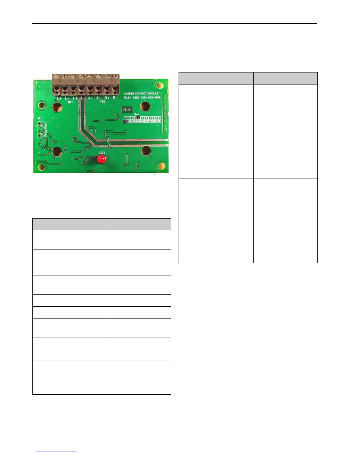
Fig. 1: CIM800 Contact Input Module
Parameter Value
Type Identification
Value:
145
System Compatibility: Use only with MX
Fire Alarm Controllers
Environment: Indoor Application
only
Operating Temperature: -25 °C to +70 °C
Storage Temperature: -40 °C to +80 °C
Operating Humidity: Up to 95 % non-
condensing
Dimensions (HWD): 87 x 148 x 14 mm
Weight: 100 g
Mounting Requirements:
One MK backbox
surface mount or an
ANC-8 ancillary
housing
Table 1: Technical Specifications
Battery Requirements:
Standby current:
Alarm current:
0.505mA
4.5mA
Wire Size:
Min 1.5 mm
2
Max 2.5 mm
2
Maximum Wiring
Resistance Monitored
Circuit:
10 ohm
Addressable Device
Conditions:
Normal
Active
Short Circuit wir-
ing fault
Open Circuit
wiring fault
Device Type
Invalid
Device No
Response
Parameter Value
Table 1: Technical Specifications
Page 2

2/8 Installation Instructions Doc. version 4.0
MZX CIM800 MZX Fire detection system
Two spur circuits (Class B) monitoring single
normally closed contacts, with short circuit
giving a fault output.
Single loop circuit (Class A) monitoring a nor-
mally open contact, with short circuit giving a
fault output.
Single loop circuit (Class A) monitoring a nor-
mally closed contact, with short circuit giving
a fault output.
Two spur circuits (Class B) monitoring multi-
ple normally open contacts, with short circuit
giving an alarm.
Single loop circuit (Class A) monitoring multi-
ple normally open contacts, with short circuit
giving an alarm.
Features
The CIM800 monitoring features include the following configurable items:
Identifies all monitored contacts and signals to
the Fire Controller, the status of monitored
contacts and wiring to the contacts.
Can monitor a single normally closed contact.
Can monitor two Class B spur circuits, or a sin-
gle class Class A loop circuit.
When two Class B spur circuits are con-
nected, each must be of the same style. A
monitored contact going to the active state, on
either spur circuit, will cause the CIM800 to
report the Active State back to the MX controller.
An LED reports the CIM800 status to the user.
The LED lights when the contact monitored by
the CIM800 has switched to the active (off
normal) state.
The LED when normally off, will pulse when
the CIM800 is polled by the controller.
Wiring notes
Mounting
Installation of modules into an ANC8 ancillary housing
The housing can accommodate up to eight ancillary PCBs. A stacking kit is available if a second
layer of PCBs is required.
How to install MX800 modules into an
ANC-8 ancillary housing
1 Assemble the required ancillary PCBs onto the
chassis plate as required, fixing as shown in Fig. 3.
2 Assemble the chassis plate into the housing and
secure using fixing screw, see Fig. 2.
NOTICE
There are no user- circuit required set-
tings (such as switches or headers) on
the CIM800.
All wiring must conform to the current
edition of IEE Wiring Regulations and
BS5839 part 1.
All conductors to be free of earths.
Fit the PCB to the M520 cover/ANC-8
ancillary housing.
Connect wiring to the monitored con-
tact. For CIM800 typical wiring configurations (see Figures 6 to 11).
Verify the correct polarity of wiring
before connecting the CIM800 to the
addressable loop
Page 3
Mounting MZX CIM800
Installation Instructions Doc. version 4.0 3/8
3 Connect the chassis plate earth lead to the hous-
ing, see Fig. 2.
Installation to M520 double gang
cover
How to install MX800 modules to an
M520 double gang cover
1 Assemble the CIM800 to the M520 Double Gang
cover, using the four screws and washers provided,
2 Fit cover onto MK backbox.
3
If an IP22 rating is required additional sealing
must be applied. Apply Loctite S1595
silicone
sealant around the LED, as shown in Fig. 5.
Note how the sealant fills the small gap
between the LED and its hole in the cover.
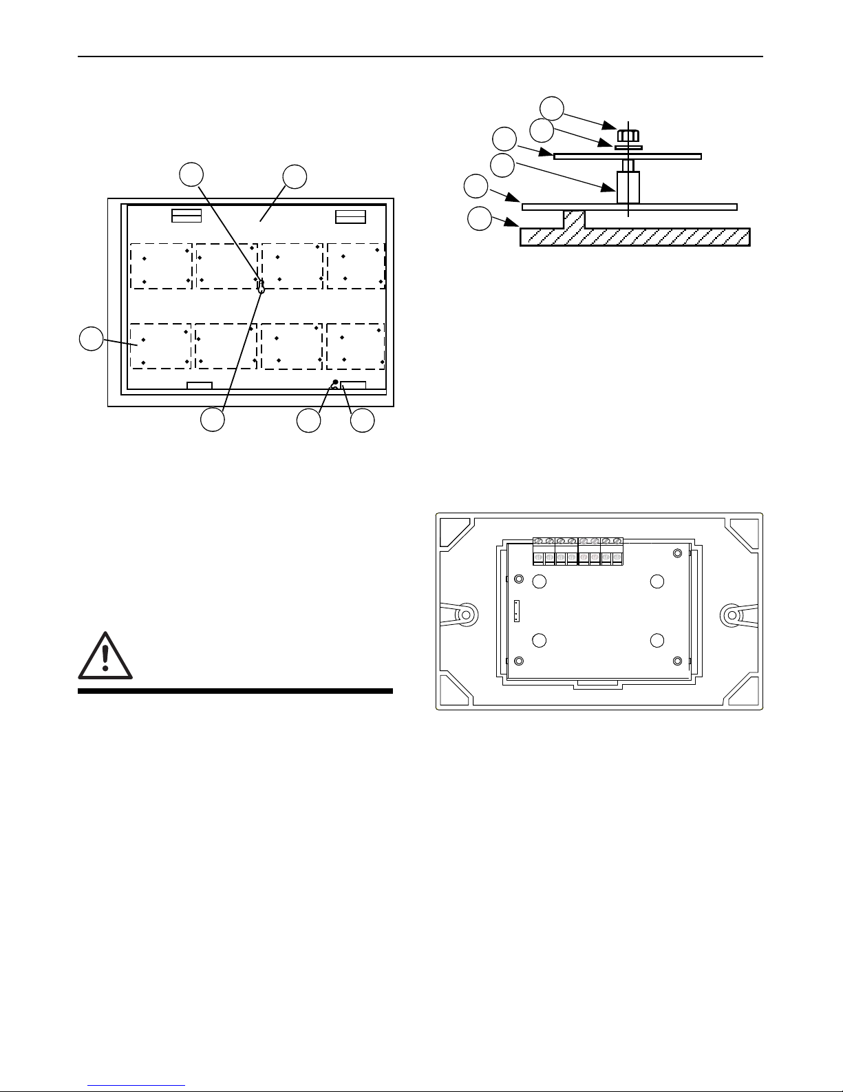
Fig. 2: A
NC-8 - Chassis Plate
1 – Chassis plate fixing screw
2 – Chassis plate
3 – Cover earth
4 – Chassis plate earth
5 – Transit screw
6 – Typical positions of 800 modules (4 per row)
CAUTION
Ensure only nylon stand-offs and
washers are used.
1
2
3
4
5
6
Fig. 3: ANC-8 - PCB Fixing Detail
1 – Housing
2 – Plate
3 – Nylon spacer
4 – Ancillary PCB.
5 – Plain washer
6 – Nylon nut
Fig. 4: CIM800 Fitted to Cover
2
3
4
5
6
1
TB1
TB2
A+ A- B+ B-
L+ L- L+ L-
PROGRAMMING
PORT
Page 4

4/8 Installation Instructions Doc. version 4.0
MZX CIM800 MZX Fire detection system
Avoid smearing sealant over the LED surface.
Using a fine nozzle is recommended.
Address settings
The CIM800 has a default factory set address of
255, this must be set to the loop address of the
device using the 801AP MX Service Tool. The
CIM800 may be programmed with the address
prior to being installed by using the internal programming port (see Fig. 4) or after being installed
by using the programming port on the front
cover (see Fig. 6).
Cabling
Cables are to be selected in accordance with
Publication 17A-02-D and the requirements of
the current issue of BS5839. Two pairs of connection terminals (L+ and L-) are provided on the
terminal block. These terminals are used for connecting the module onto the addressable circuit.
A maximum of one 1.5mm
2
or one 2.5mm2
cable may be connected at any one terminal.
Associated equipment
The module fits onto a standard dual-gang MK
box, or an ANC8 ancillary housing.
Fig. 5: Sealed LED
1 – Cover
2 – LED
3 – Sealant
1
2
3
NOTICE
Once the address has been
programmed, take note of the device
location and address number, to
include on site drawings.
Fig. 6: CIM800 Contact Input Module Facia Plate
1 – Address setting port
NOTICE
If only one circuit is used the user circuit
must be terminated with 200/100
ohm resistors in parallel or a single 68
ohm EOL resistor.
MX CONSYS configuration selection –
style C (normally closed)
Mode 3
CIM800
2
5
1
Page 5

Associated equipment MZX CIM800
Installation Instructions Doc. version 4.0 5/8
Fig. 7: Spur Circuits (Class B) Normally Closed Contacts
Short Circuit A+ to A- or B+ to B = Fault
1 – MX Controller
2 – To next device
3 – Programming port
+VE
-VE
TB1
TB2
A+ A- B+ B-
L+ L- L+ L-
100
200
100
200
1
2
3
NOTICE
If only one circuit is used the user circuit
must be terminated with 200 ohm
EOL resistor.
MX CONSYS configuration selection –
style C (normally open)
Mode 2
Page 6

6/8 Installation Instructions Doc. version 4.0
MZX CIM800 MZX Fire detection system
Fig. 8: Spur Circuits (Class B) Normally Open Contacts
Short Circuit A+ to A- or B+ to B- = Fault
1 – MX Controller
2 – To next device
3 – Programming port
NOTICE
MX CONSYS configuration selec-
tion – style E (normally closed)
Mode 6
+VE
-VE
TB1
TB2
A+ A- B+ B-
L+ L- L+ L-
100
200
100
200
1
2
3
Fig. 9: Loop Circuit (Class A) Normally Closed Contact
Short Circuit A+ to A- or B+ to B- = Fault
1 – MX Controller
2 – To next device
3 – Programming port
NOTICE
MX CONSYS configuration selection –
style E (normally open)
Mode 5
+VE
-VE
TB1
TB2
A+ A- B+ B-
L+ L- L+ L-
100
200
1
2
3
Page 7

Associated equipment MZX CIM800
Installation Instructions Doc. version 4.0 7/8
Fig. 10: Loop Circuit (Class A) Normally Open Contact
Short Circuit A+ to A- or B+ to B- = Fault
+VE
-VE
TB1
TB2
A+ A- B+ B-
L+ L- L+ L-
100
200
1
2
3
NOTICE
MX CONSYS configuration selection
– style B (normally open)
Mode 1
If only one circuit is used, the other cir-
cuit must terminated with A 200 ohm
EOL resistor
Fig. 11: Spur Circuit (Class B) Normally Open Contacts
Short Circuit between A+ and A- or B+ and B- = Alarm
1 – MX Controller
2 – To next device
3 – Programming port
+VE
-VE
TB1
TB2
A+ A- B+ B-L+ L- L+ L-
200
200
3
2
1
Page 8

MZX CIM800 Ordering information
© Tyco Fire & Security GmbH, Victor von Bruns-Strasse 21, 8212 Neuhausen
am Rheinfall, Switzerland
www.zettlerfire.com
120.415.527_17A-03-CIM, doc. version 4.0, 5. May 2016
Subject to change without notice.
Ordering information
NOTICE
MX CONSYS configuration selection –
style D (normally open)
Mode 4
Fig. 12: Loop Circuit (Class A) Normally Open Contacts
Short Circuit between A+ and A- or B+ and B- = Alarm
1 – MX Controller
2 – To next device
3 – Programming port
+VE
-VE
TB1
TB2
A+ A- B+ B-L+ L- L+ L-
200
3
2
1
Name Stock code
number
CIM800 Contact Input Module 555.800.002
CIM800 Contact Input Module:
c/w cover
555.800.032
M520 Double-Gang Cover 517.035.007
ANC8 Ancillary Housing assy. 557.180.096.T/
A/Y
Table 2: Ordering information
 Loading...