

Tyco BFV-N User Manual
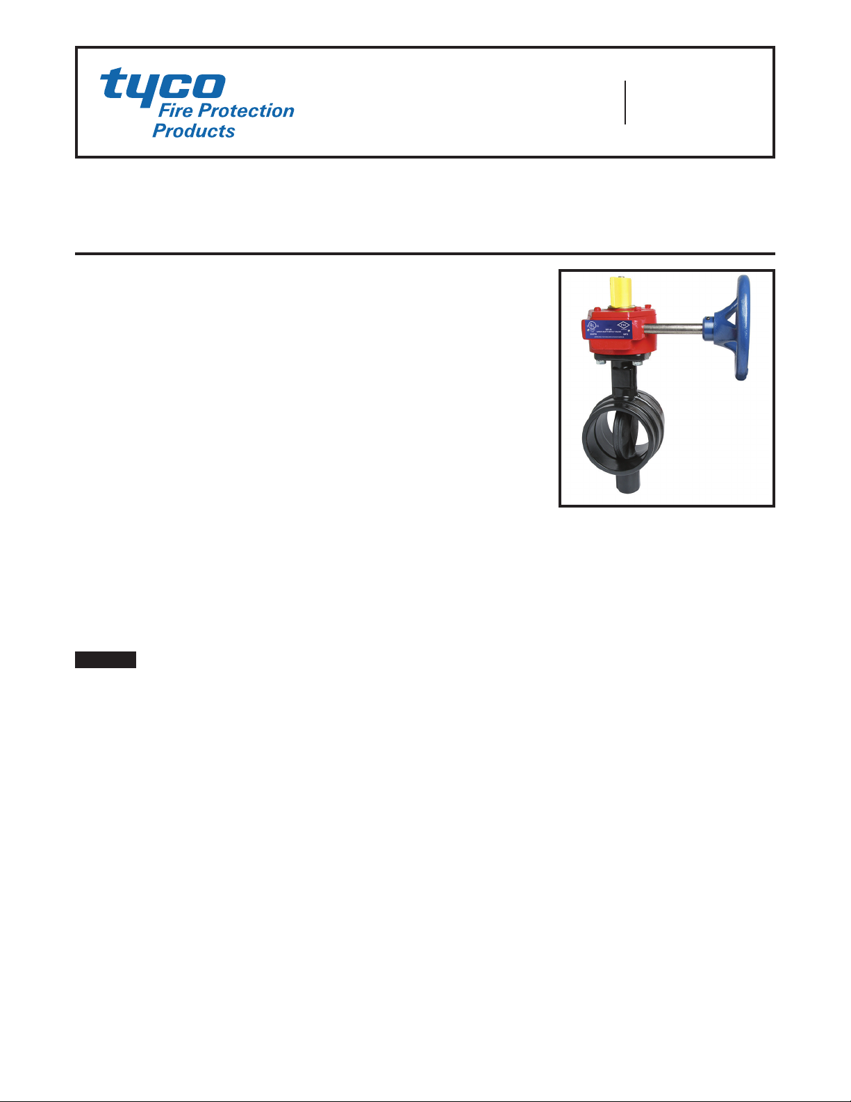
Model BFV-N Butterfly Valve
Grooved End
Worldwide
Contacts
www.tyco-fire.com
General
Description
The Model BFV-N Grooved End Butterfly Valves (Ref. Figure 1) are indicating type valves designed for use in
fire protection systems where a visual
indication is required as to whether the
valve is open or closed. They are used,
for example, as system, sectional, and
pump water control valves. They have
cut groove inlet and outlet connections
that are suitable for use with grooved
end pipe couplings that are listed and
approved for fire protection systems.
For applications requiring supervision
of the open position of the valve, the
Gear Operators for the Model BFV-N
Butterfly Valves are provided with
two sets of factory installed internal switches each having SPDT contacts (Ref. Figure 3). The supervisory
switches transfer their electrical contacts when there is movement from the
valve’s normal open position during the
first two revolutions of the handwheel.
NOTICE
The Model BFV-N Grooved End Butterfly Valves described herein must be
installed and maintained in compliance
with this document, as well as with the
applicable standards of the National
Fire Protection Association, in addition
to the standards of any other authorities having jurisdiction. Failure to do so
may impair the performance of these
devices.
The owner is responsible for maintaining their fire protection system
and devices in proper operating condition. Contact the installing contractor or product manufacturer with any
questions.
Technical
Data
Approvals
UL and C-UL Listed
FM Approved
Listed by California State Fire Marshall
under Listing No. 7770-1670:100
All laboratory listings and approvals are for
indoor and outdoor use.
Sizes
2-1/2 thru 10 Inch (DN65 thru DN250)
Maximum Working Pressure
2-1/2 to 8 Inch (DN65 to DN200)
300 psi (20,7) bar
10 Inch (DN250)
175 psi (12,0 bar)
Materials of Construction
Body
Ductile iron conforming to ASTM A395
Body Coating
Polyamide
Disc
Ductile iron conforming to ASTM A395
Disc Seal
Grade EPDM “E” encapsulated rubber
conforming to ASTM D2000
Upper & Lower Stem
Type 416 Stainless Steel
ASTM 582
Lower Plug
PVC
Operator
Gear operator with iron housing
conforming to
Page 1 of 4 JULY 2015 TFP1510
TF P1510
SWITCH SHOWN
INDICATOR
OPERATOR
CONNECTION
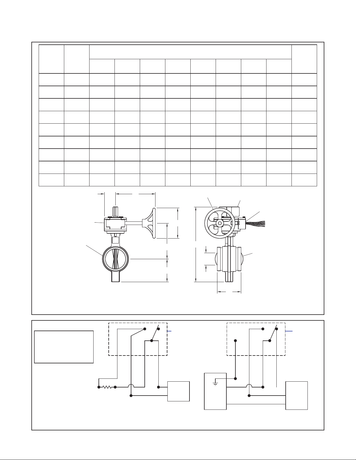
A
Page 2 of 4
Nominal
Valve
Sizes
Inches
(DN)
2-1/ 2
(65)
76 ,1mm
(65)
3
(80)
4
(100)
5
(125)
16 5 ,1m m
(150 )
6
(150 )
8
(200)
10
(250)
Pipe
OD
Inches
(mm)
2.88
(73,0)
3.00
(76 ,1)
3.50
(88,9)
4.50
(114, 3)
5.56
(141,3)
—
(165,1)
6.63
(168 ,3 )
8.63
(219,1)
10.75
(27 3 ,1)
Nominal Installation Dimensions
Inches (mm)
A B C D E F G H
3.85
(98,0)
3.85
(98,0)
3.85
(98,0)
4.56
(116,0)
5.86
(149,0)
5.86
(149,0)
5.86
(149,0)
5.26
(134 ,0 )
6.29
(160 ,0)
11. 9 4
(303,3)
11. 9 4
(303,3)
12.4 8
(317, 0 )
14.18
(360,2)
15 .17
(385,3)
17. 5 4
(445,5)
17. 5 4
(445,5)
19.42
(493,3)
24.03
(610,4)
G
3.25
(83,0)
3.25
(83,0)
3.54
(90,0)
4.35
(110,0)
4.84
(123,0)
5.93
(151,0)
5.93
(151,0)
6.87
(174 , 0 )
9.17
(233,0)
5.67
(144, 0)
5.67
(144, 0)
5.94
(150 ,9 )
6.31
(160 ,3)
7.3 2
(185 ,9 )
8.62
(218,9 )
8.62
(218,9 )
9.80
(248,9)
11.61
(294,9)
5.90
(149, 9)
5.90
(149, 9)
5.90
(149, 9)
5.90
(149, 9)
5.90
(149, 9)
5.90
(149, 9)
5.90
(149, 9)
9.80
(248,9)
18.00
(4 57, 2 )
F HANDWHEEL
5.82
(1 47,8)
5.82
(1 47,8)
5.82
(1 47,8)
7.6 4
(194,1)
7.6 4
(194,1)
7.6 4
(194,1)
7.6 4
(194,1)
7.91
(200,9)
9.49
(241,0)
FLAG
2.13
(54,1 )
2.13
(54,1 )
2.13
(54,1 )
2.13
(54,1 )
2.13
(54,1 )
2.13
(54,1 )
2.13
(54,1 )
2.13
(54,1 )
3.03
( 7 7, 0 )
1/2" NPT
CONDUIT
0
0
0
0
0
0.67
(17,0 )
0.67
(17,0 )
5.86
(148,8)
7.41
(188 ,2)
Weight
Lbs.
(kg)
22
(10,0)
22
(10,0)
23
(10,4)
28
(12,7 )
31
(14,1 )
41
(18,6)
41
(18,6)
53
(24 ,1)
88
(40,0)
GEAR
BODY
CONTACT RATING:
1/2A @ 125 VDC
1/4A @ 250 VDC
15.1A/12HP @ 125, 250 VAC
5A @ 125 VAC "L"
MODEL BF V-N GROOVED END BUT TERFLY VALVE
END OF LINE
RESISTOR
YELLOW
D
C
FIGURE 1
NOMINAL DIMENSIONS
YELLOW
ORANGE
ORANGE
E
B
SUPERVISORY
SWITCH
SWITCH SHOWN
WITH VALVE
FULL OPEN
PANEL
H
POWER
DISC
GND
RED
VIOLET
GREEN
+
- -
BLUE
AUXILIARY
SWITCH
WITH VALVE
FULL OPEN
BELL
+
MODEL BF V-N BUTTERFLY VALVE
FIGURE 2
INTERNAL SWITCH WIRING DIAGRAM WITH VALVE IN OPEN POSITION
 Loading...