

Page 1
Model BFV-300/BFV-300C
Butterfly Valve
Grooved End
Worldwide
Contacts
www.tyco-fire.com
General
Description
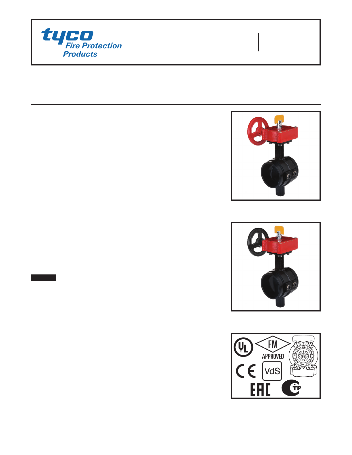
The TYCO Models BFV-300 and BFV300C Grooved End Butterfly Valves
are indicating type valves designed for
use in fire protection systems where
a visual indication of open or closed
valve condition is required. They are
used, for example, as system, sectional and pump water control valves.
They have grooved inlet and outlet connections that are suitable for use with
grooved end pipe couplings listed or
approved for fire protection systems.
For applications requiring supervision of the open or closed state of the
valve, the Gear Operators for the Model
BFV-300/BFV-300C Butterfly Valves
feature two sets of factory installed
internal switches each having SPDT
contacts ( Ref. Figure 3). The supervisory switches transfer their electrical contacts when there is movement
from the open or closed disc position
during the first two revolutions of the
handwheel.
NOTICE
The Model BFV-300/BFV-300C
Grooved End Butterfly Valves described
herein must be installed and maintained
in compliance with this document, as
well as with the applicable standards
of the National Fire Protection Association, in addition to the standards of
any other authorities having jurisdiction.
Failure to do so may impair the performance of these devices.
The owner is responsible for maintaining their fire protection system
and devices in proper operating condition. Contact the installing contractor or product manufacturer with any
questions.
Technical
Data
Approvals
UL Listed
FM Approved
CE Certified
VdS Approved
Russian Fire Certificate
CNPP R1 Li sted – APSAD
Listed by California State Fire Marshall
Refer to Tables A, B and C for applicability.
All laboratory listings and approvals are for
indoor and outdoor use.
Sizes
2 – 12 Inch ( DN50 – DN30 0)
UL/FM Maximum Working Pressure
2 – 8 Inch (D N50 – DN200 ) . . . . 300 psi ( 20,7 bar)
10 – 12 I nch (D N250 – DN30 0) . . 175 psi (12,1 bar)
VdS Maximum Working Pressure
2 – 8 Inch (D N50 – DN200 ) . . . . 300 psi ( 20,7 bar)
10 Inch (DN250) . . . . . . . . . . . 232 psi (16,0 bar)
12 Inch (DN300 ) . . . . . . . . . . . . 175 psi (12,1 bar)
Maximum Working Temperature
212°F (100°C) in accordance with UL 1091
Materials of Construction
Body . . . . . . . . . . . . . . . . . . . . . . . . . Ductile Iron
Body Coating . . . . . . . . . . . RILSAN PA11 Black
Disc . . . . . . . . . . . . . . . . . . . . . . . . . . Ductile Iron
Disc Seal ...............EPDM Encapsulated
Upper & Lower Stem . . . . . . . . . . Stainless Steel
Handwheel . . . . . . . . . . . . . . . . . . . . Ductile Iron
(BFV-300 red painted; BFV-300C black painted)
Actuato r, 2 – 6 Inch (D N50 – DN150) :
• IP 65, bronze traveling nut gea rbox, ductile
iron housing
Actuato r, 8 – 12 In ch (DN 200 – DN30 0):
• IP 65, brass segmented gearbox, ductile iron
housing
Tapping Bosses
Two factory-plugged NPT threaded tapping
bosses in the valve body are located on the
up- and downstream sides of the disc for
connection to valve trim. Tapping boss
sizes:
2 – 3 inch (D N50 – DN80 ) .............3/8 NPT
4 – 12 inch ( DN100 – DN30 0) ..........1/2 NPT
MODEL BFV-300
WITH OPEN SUPERVISORY
SWITCHES
MODEL BFV-300C
WITH CLOSED SUPERVISORY
SWITCHES
100% Silicone Free
Model BFV-300/BFV-300C Butterfly Valves
are produced and assembled using no
silicone lubricants in any form (like grease
or aerosol spray) and are suitable for paint
or oxygen applications.
Control Valve Seat Leakage
Class IEC 60534-4
CLASS VI (Type C) Control Valve Seat
Leakage according to ANSI/FCI
70-2-2006 (ASME B16.104)
Page 1 of 8 JUNE 2016 TFP1511
Page 2
TF P1511
A
OPERATOR
HANDWHEEL
1/2" NPT
INDICATOR
J
Page 2 of 8
Nominal
Valve Size
Inches
(DN)
2
(DN50)
2-1/ 2
(DN65)
—
(DN65)
3
(DN80)
4
(DN100)
—
(D N125)
5
(D N125)
—
DN15 0
6
(DN150)
8
(DN200)
10
(DN250)
—
(DN250)
12
(DN300)
—
(DN300)
Pipe
OD
Inches
(mm)
2.37
(60,3)
2.88
(73,0)
3
76 ,1
3.5
(88,9)
4.5
(114,3)
5.5
(139,7)
5.56
(141,3)
6.5
16 5 ,1
6.63
(168 ,3)
8.63
(219,1)
10.75
(273)
10.75
(273)
12.75
(323,9)
12.75
(323,9)
Nominal Dimensions
Inches
(mm)
A B C D E F G H J
3.8
(96,4)
3.8
(96,4)
3.8
(96,4)
3.8
(96,4)
4.54
(115,4)
5.83
(148)
5.83
(148)
5.83
(148)
5.83
(148)
5.24
(133 )
6.26
(159)
6.26
(159)
6.5
(165 )
6.5
(165 )
10.6 3
(270)
11.72
(297, 8 )
11.72
(297, 8 )
12.22
(310,3)
13.92
(353,5)
16
(406,6)
16
(406,6)
17. 0 7
(433,6)
17. 0 7
(433,6)
19.67
(499,5)
22.46
(570,5)
22.46
(570,5)
25.39
(645)
25.39
(645)
2.85
(72,5)
3.35
(85)
3.35
(85)
3.58
(91)
4.29
(109 )
5.16
(131)
5.16
(131)
5.71
(145)
5.71
(145)
6.69
(170)
7.6 8
(195 )
7.6 8
(195 )
9.5
(241,5 )
9.5
(241,5 )
4.90
(124, 5)
5.5
(139,8 )
5.5
(139,8 )
5.76
(146, 3 )
6.75
(171,5)
7.9 3
(201,5)
7.9 3
(201,5)
8.44
(214, 5)
8.44
(214, 5)
9.29
(236)
11.1
(282)
11.1
(282)
12.2
(310)
12.2
(310)
4.92
(125)
4.92
(125)
4.92
(125)
4.92
(125)
4.92
(125)
5.91
(150 )
5.91
(150 )
5.91
(150 )
5.91
(150 )
8.86
(225)
11.14
(283)
11.14
(283)
11.14
(283)
11.14
(283)
4.28
(108 ,6)
4.28
(108 ,6)
4.28
(108 ,6
4.28
(108 ,6)
4.28
(108 ,6)
5.79
(147 )
5.79
(147 )
5.79
(147 )
5.79
(147 )
8.19
(208)
8.19
(208)
8.19
(208)
8.19
(208)
8.19
(208)
1.9 9
(50,5)
1.9 9
(50,5)
1.9 9
(50,5)
1.9 9
(50,5)
1.9 9
(50,5)
2.32
(58,9)
2.32
(58,9)
2.32
(58,9)
2.32
(58,9)
2.76
(70)
2.91
(74)
2.91
(74)
2.91
(74)
2.91
(74)
0 0
0 0
0 0
0 0
0 0
0 0
0 0
0 0
0 0
5.66
(143,7)
7. 2 1
(183 ,1)
7. 2 1
(183 ,1)
9.96
(252,9)
9.96
(252,9)
1.24
(31, 4)
1.65
(41,8)
1.65
(41,8)
2.7
(68,5)
2.7
(68,5)
Weight
Lbs.
(kg)
10.8
(4,9)
13.0
(5,9)
13.0
(5,9)
13.9
(6,3)
17. 6 4
(8,0)
26.4
(11,9)
26.4
(11,9)
30,42
(13, 8)
30,42
(13, 8)
47.1 8
(21, 4)
73.41
(33,3)
73.41
(33,3)
89.29
(40,5)
89.29
(40,5)
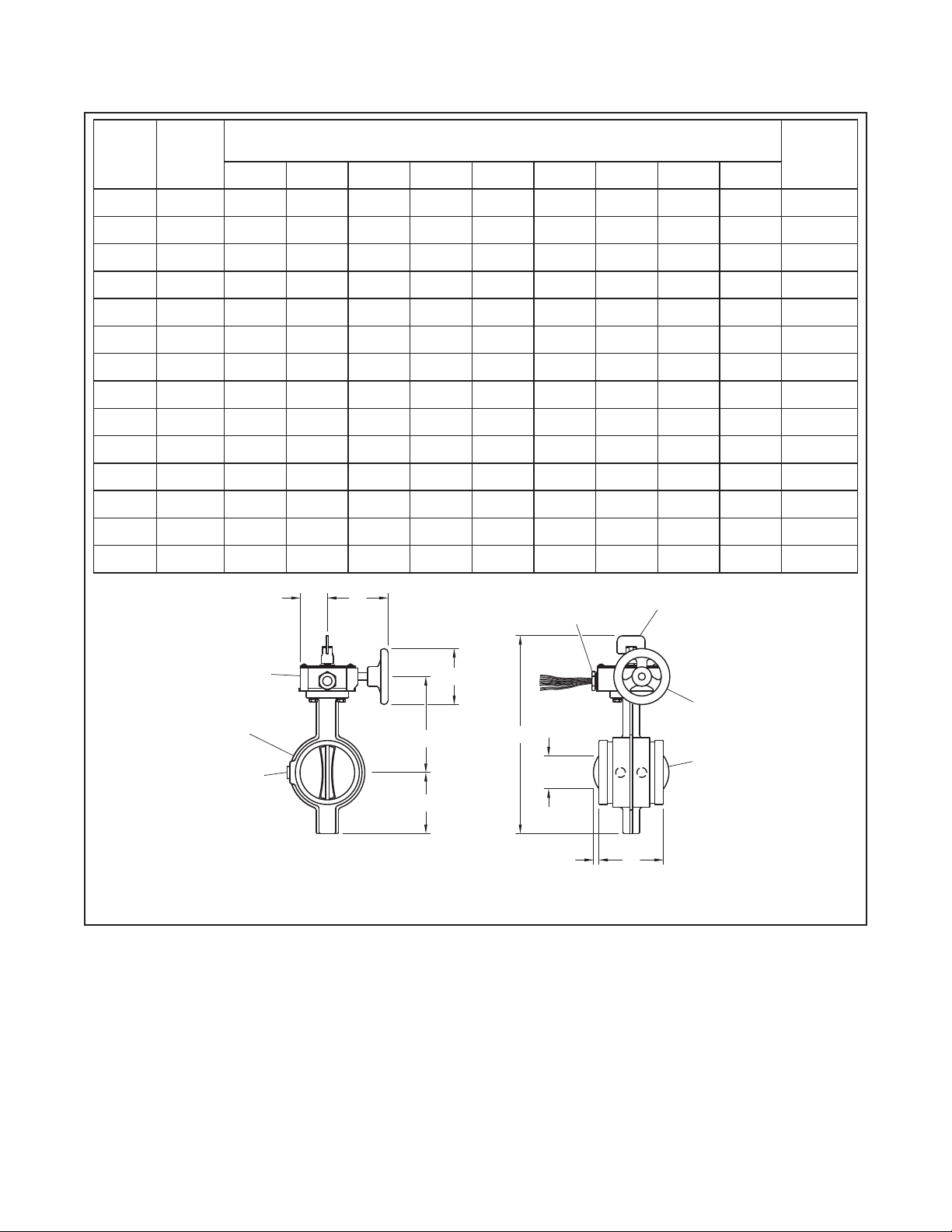
G
GEAR
BODY
TAPPING
BOSSES
F
E
D
C
CONDUIT
CONNECTION
B
H
FIGURE 1
MODEL BF V-300/BF V-30 0C GROOVED END BUTTERFLY VALVE
NOMINAL DIMENSIONS
FLAG
DISC
Page 3
TF P1511
Page 3 of 8
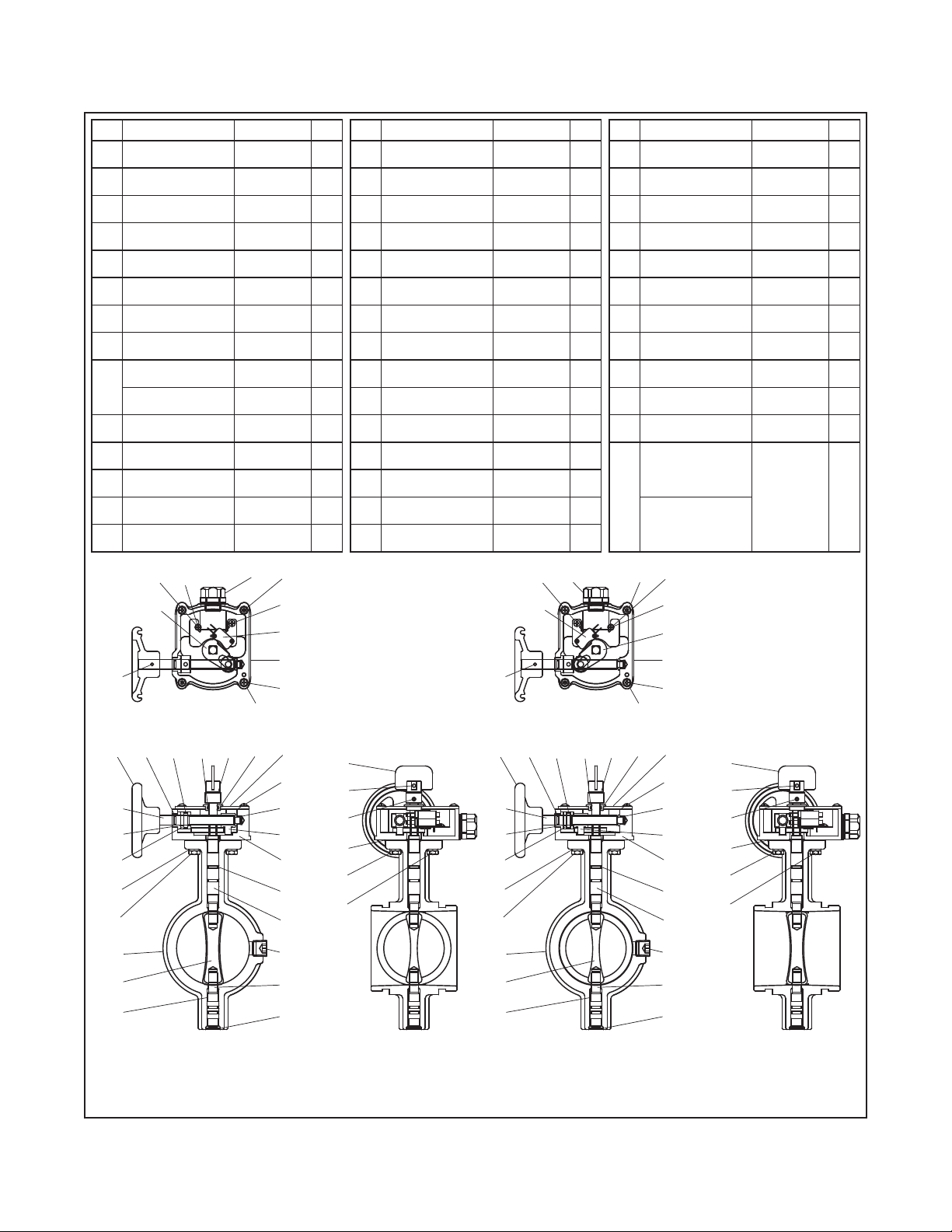
No. Part Material Qty.
01 Body
02 Upper Stem AI SI 410 1
03 Lower Stem AI SI 410 1
04 Disc EPDM 1
05 O- Rin g (P12) EPDM 4
06
07
08 Gear Box
09
10 Bushing (2) FD-0205-45 1
11 Cover
12 Bushing Fe 1
13
14 Stem Housing Fe 1
Oiless B/R
(M B1410)
End Cap
2-1/2 – 4 Inch
Traveling Nut
2 – 6 Inch
Segment Gear
8 – 12 Inch
Headless Wrench
Bolt M5 x 7L
35
34
ASTM
A-536
— 4
EPDM 1
ASTM
A-536
Bronze 1
C3604BD 1
ASTM
A- 619
ASTM
A-307
37 33
1
1
1
1
No. Part Material Qty.
15 Spring Pin
16 Indicator
17 O-Ring NBR 1
18 Cover Gasket Paper 1
19
20 O-Ring (P10) EPDM 1
21 Worm Shaf t A ISI 410 1
22 Bushing (1) FD-0205-45 1
23 Collar FD-0205-45 1
24 Spring Washer
25
26
27 Gasket Paper 1
28
29 Handwheel
Spring Pin
Ø5 x 1T x 25
Hex Bolt
M8 x 20L
Hex Bolt
M8 x 25L
Spring Pin
Ø4 x 0.8t x 25
ASTM
A-228
ASTM
A- 619
ASTM
A-228
ASTM
A-167
ASTM
A-167
ASTM
A-167
ASTM
A-228
ASTM
A-536
30
1
1
1
4
2
2
1
1
37
No. Part Material Qty.
30 Bolt (Round)
31 Plate Washer
32 Switch Assembly — 1
33 T/R Bolt
Tapping Screw
34
35 Tooth Washer 4# S10C 1
36 Lever
37 Connector — 1
38 Sticker — 1
39 Sticker — 1
40
41
ST3.5 x 7.5
Spring Pin
Ø3 x 0.6T x 25
Headless Plug
3/8 NPT
2 – 3 Inch
Headless Plug
1/2 N PT
4 – 12 Inch
35
33
ASTM
A-167
ASTM
A-167
ASTM
A-307
S10C 1
ASTM
A- 619
ASTM
A-228
ASTM
A-307
3
4
2
1
1
2
28
29
21
22
23
24
25
01
04
06
30
1214
30
32
38, 39
31
18
11
10
09
08
05
02
41
03
07
20
36
19,
40
17
BFV-300 Normally Open Valve
Supervisory Switch Arrangement
MODEL BF V-300/BF V-30 0C GROOVED END BUTTERFLY VALVE
16
15
13
27
25
26
28
29 20
21
22
23
24
25
01
04
06
FIGURE 2
AS S E M B LY
30
12
34
36
38, 39
31
18
11
10
09
08
05
02
41
03
07
32
19,
40
17 14
BFV-300C Normally Closed Valve
Supervisory Switch Arrangement
16
15
13
27
25
26
Page 4

TF P1511
12 INCH (DN300)
10 INCH (DN250)
NOMINAL PRESSURE DROP
IN POUNDS PER SQUARE INCH (PSI)
NOMINAL PRESSURE DROP IN BAR
(1 PSI = 0,06895 BAR)
FLOW RATE IN GALLONS PER MINUTE (GPM)
FLOW RATE IN LITERS PER MINUTE (LPM)
YELLOW
YELLOW
Page 4 of 8
200 400020001000600400 20000100006000
9.0
8.0
7.0
6.0
5.0
4.0
2.0
2.0
1.0
0.9
0.8
0.7
0.6
0.5
0.4
2 INCH (DN50)
2-1/2 INCH (DN65)
(1 GPM = 3,785 LPM)
3 INCH (DN80)
4 INCH (DN100)
5 INCH (DN125)
6 INCH (DN150)
8 INCH (DN200)
0,60
0,50
0,40
0,30
0,20
0,10
0,09
0,08
0,07
0,06
0,05
0,04
0,03
0.3
6050 80 100 200 400020001000800600400 6000
FIRE ALARM
CONTROL PANEL
SUPERVISORY
CIRCUIT
CONTACT RATINGS:
16A 125V/250 VAC
5A 24VDC
SWITCH S-1, 2 LEADS PER CONTACT
SWITCH S-2, 1 LEAD PER CONTACT
MODEL BF V-300 BUTTERFLY VALVE OPEN POSITION — SUPERVISORY SWITCH OPEN POSITION
MODEL BF V-300C BUTTERFLY VALVE CLOSED POSITION — SUPERVISORY SWITCH CLOSED POSITION
VOLTAGE
SOURCE
MODEL BF V-300/BF V-30 0C GROOVED END BUTTERFLY VALVE
GRAPH A
MODEL BFV-300/BFV-300C
NOMINAL PRESSURE DROP VERSUS FLOW
S-1
COMMON (WHITE)
RED
GEAR OPERATOR
S-2
COMMON (BLACK)
COMMON (WHITE)
RED
GREEN
BLUE
ORANGE
FIGURE 3
INTERNAL SWITCH WIRING DIAGRAM
END OF LINE
RESISTOR
OR
NEXT DEVICE
OPERATOR CASE
GROUND
AUX. DEVICE
(BELL OR HORN)
Page 5

TF P1511
Page 5 of 8
Nominal
Valve Size
Inches
(DN)
2
(DN50)
2-1/ 2
(DN65)
—
DN653 76 ,1
3
(DN80)
4
(DN100)
—
DN125
5
(D N125)
—
DN15 0
6
(DN150)
8
(DN200)
10
(DN250)
—
(DN250)
12
(DN300)
—
(DN300)
Pipe
O.D.
Inches
(mm)
2.38
(60,3)
2.88
(73,0)
3,5
(88,9)
4.5
(114,3)
5.5
(139,7)
5.56
(141,3)
6.5
(16 5,1)
6.63
(168 ,3)
8.63
(219,1)
10.75
(273)
10.75
(273)
12.75
323,9
12.75
323,9
Max.
PSI
(bar)
(20,7 )
(20,7 )
(20,7 )
(20,7 )
(20,7 )
(20,7 )
(20,7 )
(20,7 )
(20,7 )
(20,7 )
(12,1)
(12,1)
(12,1)
(12,1)
Supv. Switch
300
59300G020WS 59300G020WSC
300
59300G025WS 59300G025WSC
300
59300G026WS 59300G026WSC
300
59300G030WS 59300G030WSC
300
59300G040WS 59300G040WSC
300
59300G056WS 59300G056WSC
300
59300G050WS 59300G050WSC
300
59300G066WS 59300G066WSC
300
59300G060WS 59300G060WSC
300
59300G080WS 59300G080WSC
175
59300G100WS 59300G100WSC
175
59300G106WS 59300G106WSC
175
59300G120WS 59300G120WSC
175
59300G126WS 59300G126WSC
Part Number Agency Listing/Approval
BFV-300
OPEN
BFV-300C
Supv. Switch
CLOSED
CE UL FM VdS
✓ ✓ ✓ ✓
✓ ✓ ✓ ✓ ✓ ✓ ✓
✓ ✓ ✓ ✓ ✓ ✓
✓ ✓ ✓ ✓ ✓ ✓ ✓
✓ ✓ ✓ ✓ ✓ ✓ ✓
✓ ✓ ✓ ✓ ✓
✓ ✓ ✓ ✓ ✓ ✓
✓ ✓ ✓ ✓ ✓ ✓
✓ ✓ ✓ ✓ ✓ ✓ ✓
✓ ✓ ✓ ✓ ✓ ✓ ✓
✓ ✓ ✓ ✓ ✓ ✓
✓ ✓ ✓ ✓ ✓ ✓
✓ ✓ ✓ ✓
✓ ✓ ✓ ✓
TABL E A
MODEL BF V-300/BF V-30 0C GROOVED END BUTTERFLY VALVE
WITH INTERNAL SUPERVISORY SWITCHES
PART NUMBER SELECTION AND AGENCY LISTINGS/APPROVALS
CA Fire
Marshall
CNPP PAVUS
Russian
Fire
Cert.
Nominal
Valve Size
Inches
(DN)
2
(DN50)
2-1/ 2
(DN65)
—
DN653 76 ,1
3
(DN80)
4
(DN100)
—
DN125
5
(D N125)
—
DN15 0
6
(DN150)
8
(DN200)
10
(DN250)
—
(DN250)
12
(DN300)
—
(DN300)
Pipe
O.D.
Inches
(mm)
2.38
(60,3)
2.88
(73,0)
3,5
(88,9)
4.5
(114,3)
5.5
(139,7)
5.56
(141,3)
6.5
(16 5,1)
6.63
(168 ,3)
8.63
(219,1)
10.75
(273)
10.75
(273)
12.75
323,9
12.75
323,9
Max.
PSI
(bar)
(20,7 )
(20,7 )
(20,7 )
(20,7 )
(20,7 )
(20,7 )
(20,7 )
(20,7 )
(20,7 )
(20,7 )
(12,1)
(12,1)
(12,1)
(12,1)
Supv. Switch
300
59300G020AWS 59300G020AWSC
300
59300G025AWS 59300G025AWSC
300
59300G026AWS 59300G026AWSC
300
59300G030AWS 59300G030AWSC
300
59300G040AWS 59300G040AWSC
300
59300G056AWS 59300G056AWSC
300
59300G050AWS 59300G050AWSC
300
59300G066AWS 59300G066AWSC
300
59300G060AWS 59300G060AWSC
300
59300G080AWS 59300G080AWSC
175
59300G100AWS 59300G100AWSC
175
59300G106AWS 59300G106AWSC
175
59300G120AWS 59300G120AWSC
175
59300G126AWS 59300G126AWSC
Part Number Agency Listing/Approval
BFV-300
OPEN
BFV-300C
Supv. Switch
CLOSED
CE UL FM VdS
✓ ✓ ✓ ✓
✓ ✓ ✓ ✓ ✓ ✓ ✓ ✓
✓ ✓ ✓ ✓ ✓ ✓ ✓
✓ ✓ ✓ ✓ ✓ ✓ ✓ ✓
✓ ✓ ✓ ✓ ✓ ✓ ✓ ✓
✓ ✓ ✓ ✓ ✓ ✓
✓ ✓ ✓ ✓ ✓ ✓ ✓
✓ ✓ ✓ ✓ ✓ ✓ ✓
✓ ✓ ✓ ✓ ✓ ✓ ✓ ✓
✓ ✓ ✓ ✓ ✓ ✓ ✓ ✓
✓ ✓ ✓ ✓ ✓ ✓ ✓
✓ ✓ ✓ ✓ ✓ ✓ ✓
✓ ✓ ✓ ✓
✓ ✓ ✓ ✓
CA Fire
Marshall
CNPP PAVUS
TABL E B
MODEL BF V-300/BF V-30 0C GROOVED END BUTTERFLY VALVE
WITH CNPP-APSAD LARGE 100 X 10 0 MM FL AG AND INTERNAL SUPERVISORY SWITCHES
PART NUMBER SELECTION AND AGENCY LISTINGS/APPROVALS
Russian
Fire
Cert.
Page 6

TF P1511
Page 6 of 8
Nominal
Valve Size
Inches
(DN)
2
(DN50)
2-1/ 2
(DN65)
—
DN653 76 ,1
3
(DN80)
4
(DN100)
—
DN125
5
(D N125)
—
DN15 0
6
(DN150)
8
(DN200)
10
(DN250)
—
(DN250)
12
(DN300)
—
(DN300)
Pipe
O.D.
Inches
(mm)
2.38
(60,3)
2.88
(73,0)
3,5
(88,9)
4.5
(114,3)
5.5
(139,7)
5.56
(141,3)
6.5
(16 5,1)
6.63
(168 ,3)
8.63
(219,1)
10.75
(273)
10.75
(273)
12.75
323,9
12.75
323,9
Max.
PSI
(bar)
300
(20,7 )
300
(20,7 )
300
(20,7 )
300
(20,7 )
300
(20,7 )
300
(20,7 )
300
(20,7 )
300
(20,7 )
300
(20,7 )
300
(20,7 )
175
(12,1)
175
(12,1)
175
(12,1)
175
(12,1)
Part
Number
59300G020NS
59300G025NS
59300G026NS
59300G030NS
59300G040NS
59300G056NS
59300G050NS
59300G066NS
59300G060NS
59300G080NS
59300G100NS
59300G106NS
59300G120NS
59300G126NS
CE UL FM VdS
✓ ✓ ✓ ✓
✓ ✓ ✓ ✓ ✓ ✓ ✓
✓ ✓ ✓ ✓ ✓ ✓
✓ ✓ ✓ ✓ ✓ ✓ ✓
✓ ✓ ✓ ✓ ✓ ✓ ✓
✓ ✓ ✓ ✓ ✓
✓ ✓ ✓ ✓ ✓ ✓
✓ ✓ ✓ ✓ ✓ ✓
✓ ✓ ✓ ✓ ✓ ✓ ✓
✓ ✓ ✓ ✓ ✓ ✓ ✓
✓ ✓ ✓ ✓ ✓ ✓
✓ ✓ ✓ ✓ ✓ ✓
✓ ✓ ✓ ✓
✓ ✓ ✓ ✓
Agency Listing/Approval
CA Fire
Marshall
CNPP PAVUS
TABL E C
MODEL BF V-300 GROOVED END BUTTERFLY VALVE
WITHOUT INTERNAL SUPERVISORY SWITCHES
PART NUMBER SELECTION AND AGENCY LISTINGS/APPROVALS
Russian
Fire
Cert.
Nominal
Valve Size
Inches
(DN)
2 – 4
(DN50 – DN100)
5 – 6
(DN125 – DN200)
8
(DN200)
10 – 12
(DN250 – DN 300)
Notes:
1. Install a singl e switch in e ither b racket m ountin g posit ion to mon itor Ope n or Clos ed valve c ondition
Gear
Operator
Typ e
Travelling
Nut
Segmented
Gear
Mounting
Bracket with
Mounting Bolts
59300SPBRACKET10
59300SPBRACKET20
59300SPBRACKET25
59300SPBRACKET30
Bernstein
i88-IP65
Regular Switch
59300SPSW 59300SPSWLED 59300SPSWATEX
Part Number
Bernstein
i88-IP65
LED Switch
24V
Bernstien Switch
Wiring Diagram
Bernstein
GC-SU1Z
Ex IP-66/67 ATEX
(Ex II2G Ex dIIC T6 Gb)
TABL E D
MODEL BF V-300 GROOVED END BUTTERFLY VALVE WITHOUT INTERNAL SUPERVISORY SWITCHES
ACCESSORY EXTERNAL SUPERVISORY SWITCHES AND MOUNTING BRACKETS
PART NUMBER SELECTION
Switch
Page 7

TF P1511
Page 7 of 8
Installation
The Model BFV-300/BFV-300C
Grooved End Butterfly Valves may be
installed with flow in either direction
and can be positioned either horizontally or vertically.
The grooved end pipe couplings
used with the Model BFV-300/BFV300C must be listed or approved for
fire protection service and installed in
accordance with the manufacturers
instructions.
The Model BFV-300/BFV-300C Butterfly Valve may be installed with any
schedule of pressure class of pipe or
tubing that is listed or approved for fire
protection.
Conduit and electrical connections
are to be made in accordance with
the authority having jurisdiction and/
or the National Electrical Code. With
reference to Figure 3, the supervisory
switch is intended for connection to
the supervisory circuit of a fire alarm
control panel in accordance with NFPA
72. The auxiliary switch is intended for
the unsupervised connection to auxiliary equipment in accordance with
NFPA 70, National Electric Code.
NOTE: For outdoor applications with
internal supervisory switches, it is recommended that wiring connections
be made at a temperature above 15°F
(-9°C), in order to insure sufficient flexibility of the wire lead insulation.
Care and
Maintenance
Before closing a fire protection system
control valve for maintenance or
inspection work on either the valve or
fire protection system which it controls, permission to shut down the
affected fire protection systems must
be obtained from the proper authorities
and all personnel who may be affected
by this decision must be notified.
The owner is responsible for the
inspection, testing, and maintenance of
their fire protection system and devices
in accordance with the applicable standards of the National Fire Protection
Association (e.g., NFPA 25), in addition
to the standards of any authority having
jurisdiction. Contact the installing contractor or product manufacturer with
any questions. Any impairment must
be immediately corrected.
It is recommended that automatic
sprinkler systems be inspected, tested,
and maintained by a qualified inspection service.
Nominal Valve Size
Inches
(DN)
2 – 4
(DN50 – DN100)
5 – 8
(DN125 – DN200)
10 – 12
(DN250 – DN 300)
BFV-300/BFV-300C GROOVED END BUTTERFLY VALVE
BFV-300, Red Painted BFV-300C, Black Painted
59300SPHWHEEL10 59300SPHWHEEL10B
59300SPHWHEEL20 59300SPHWHEEL20B
59300SPHWHEEL30 59300SPHWHEEL30B
TABL E E
REPLACEMENT HANDWHEEL
PART NUMBER SELECTION
Limited
Warranty
For warranty terms and conditions, visit
www.tyco-fire.com.
Ordering
Procedure
Contact your local distributor for availability. When placing an order, indicate
the full product name and Part Number
(P/N).
Butterfly Valves
Model BFV-300 with Internal
Open Supervisory Switches
Specify: (specify size) Model BFV-300
Grooved End Butterfly Valve, Internal Open Supervisory Switches,
P/N (specify per Table A)
Model BFV-300C with Internal
Closed Supervisory Switches
Specify: (specify size) Model BFV300C Grooved End Butterfly Valve,
Internal Closed Supervisory Switches,
P/N (specify per Table A)
Model BFV-300 with Internal
Open Supervisory Switches,
APSAD Approved
Specify: (specify size) Model BFV-300
Grooved End Butterfly Valve, Internal
Open Supervisory Switches, APSAD
Approved, P/N (specify per Table B)
Model BFV-300C with Internal
Closed Supervisory Switches,
APSAD Approved
Specify: (specify size) Model
BFV-300C Grooved End Butterfly Valve, Internal Closed Supervisory Switches, APSAD Approved,
P/N (specify per Table B)
Model BFV-300 without Internal
Supervisory Switches
Specify: (specify size) Model BFV-300
Grooved End Butterfly Valve,
P/N (specify per Table C)
Part Number
Accessories
External Supervisory Switch and
Mounting Bracket
Note: Accessory external supervisory switches and mounting brackets
are applicable only to valves without
factory-installed internal supervisory
switches.
Refer to Table D for switch models and
part numbers.
Specify: (specify size) Model BFV-300
Grooved End Butterfly Valve External Switch Mounting Bracket, P/N
(specify), with (specify quantity) Bernstein External Switch (specify model),
P/N (specify)
Replacement Parts
Note: Only items described in this
section are offered as replacement
parts.
Handwheel
Replacement handwheel includes pin.
Refer to Table E for part numbers.
Model BFV-300, Red Painted
Specify: Handwheel, (specify size)
Model BFV-300 Grooved End Butterfly Valve, P/N (specify)
Model BFV-300C, Black Painted
Specify: Handwheel, (specify size)
Model BFV-300C Grooved End Butterfly Valve, P/N (specify)
Page 8

TF P1511
Page 8 of 8
GLOBAL HEADQUARTERS | 1400 Pennbrook Parkway, Lansdale, PA 19446 | Telephone +1-215-362-0700
Copyright © 2016 Tyco Fire Products, LP. All rights reserved.
RILSAN is a registered t radem ark of Arkema, I nc.
 Loading...