

Page 1
Technical Services: Tel: (800) 381-9312 / Fax: (800) 791-5500
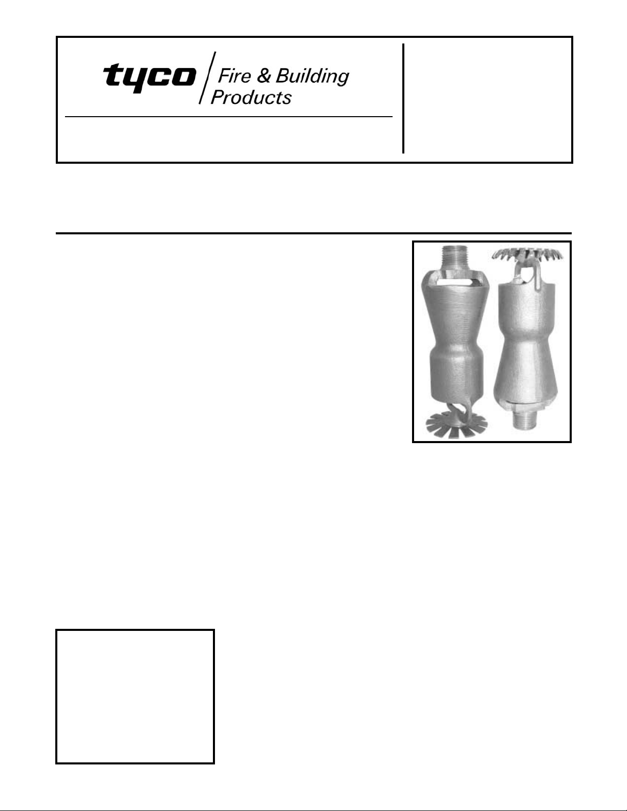
Model B-1 — 3.0 K-factor
Upright and Pendent
Foam-Water Sprinklers
tection Association, in addition to the
General
Description
The Model B-1 Upright and Pendent
Foam-Water Sprinklers are air-aspirating foam discharge outlets designed for use in foam-water deluge
systems. They are designed for flammable liquidrisks where it is desired to
apply foam from overhead sprinklers
(either upright or pendent) and where
follow-upwith plain waterina standard
spraysprinkler patternis necessaryas
in the case of NFPA 16, “Standard for
the Installation of Foam-Water Sprinkler and Foam-WaterSpray Systems”.
Itis recommended thattheend user be
consultedwith respecttothe suitability
of thematerials of construction for any
given corrosive environment. The effects of ambient temperature, concentration of chemicals,and gas/chemical
velocity, should be considered, at a
minimum, along with the corrosive nature to which the sprinklers may be
exposed.
The Model B-1 Foam-Water Sprinkler
is a redesignation for the Gem Issue
B-1 and Star Model B-1.
WARNINGS
TheModel B-1Foam-WaterSprinklers
describedherein mustbeinstalled and
maintained in compliance with this
document, as well as with the applicable standards of the National Fire Pro-
IMPORTANT
Always refer to Technical Data
Sheet TFP700 for the “INSTALLER
WARNING” that provides cautions
with respect to handling and installation of sprinkler systems and components. Improper handling and installation can permanently damage
a sprinkler system or its components and cause thesprinkler to fail
tooperate ina fire situationor cause
it to operate prematurely.
standardsof anyother authoritieshaving jurisdiction. Failure to do so may
impair the performance of thesedevices.
The owneris responsible formaintaining theirfire protectionsystem and devices in proper operating condition.
The installing contractor or sprinkler
manufacturer should be contacted
with any questions.
Technical
Data
Approvals
The M odel B-1 Upright and Pendent
Foam-Water Sprinklers are UL and
ULC Listed. (Discharge outlets and
foam concentrates are Listed for use
together. Refer to the individual foam
concentrate Listing for operating limitations and compatibility with the B-1
Foam-Water Sprinklers as providedin
the UL Fire Protection Equipment Directory.)
The M odel B-1 Upright and Pendent
Foam-Water Sprinklers meet the requirements of MIL-S-901C for lightweight Grade A shock proof equipment.
The Model B-1 Pendent Foam-Water
Sprinklers meet the requirements of
MIL-H-24146.
Maximum Working Pressure
175 psi (12,1 bar)
Discharge Coefficient
K=3.0GPM/psi
Thread Connection
1/2 inch NPT
Finishes
Natural Bronze
Physical Characteristics
Body . . . . . . . . . . . . . . Bronze
Deflector............ Brass
Agitator ............ Brass
1/2
(43,2 LPG/bar
1/2
Operation
TheModel B-1 Foam-WaterSprinklers
are designed with a unique venturi
style body. As foam solution (water
and foam concentrate mixture) flows
through the inlet of the body, air is
drawn into thebody through the openings adjacent to the wrenching area.
The foam solution and air mix is then
agitated to create an air-aspirated
foam.
The B-1 Foam-Water Sprinklers are
designed to discharge foam in a predetermined discharge pattern, as well
as to discharge water similar to standard spray sprinklers. To meet the intent of NFPA 16, foam-water sprinklers must be able to sufficiently
)
distribute water after depletion of the
foam concentrate.
Page 1 of 4 TFP840
MARCH, 2006
Page 2
Page2of4
TFP840
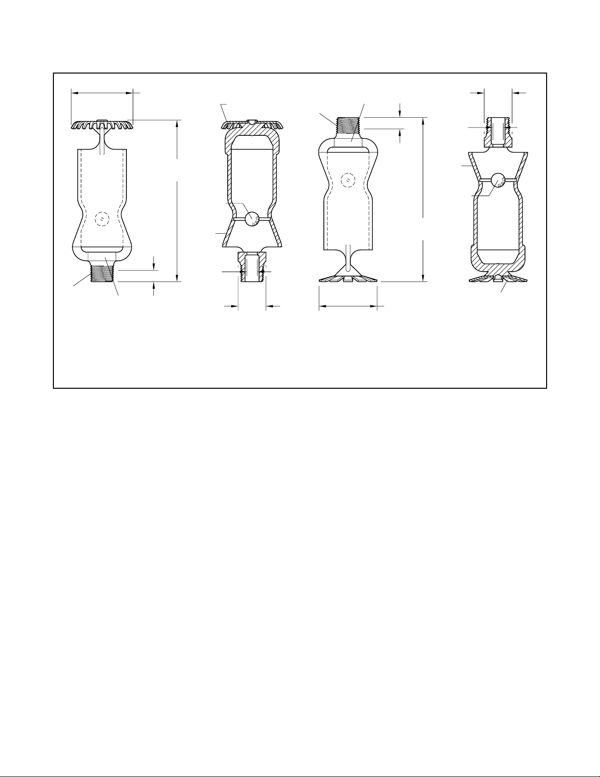
1/2"
NPT
(11,1 mm)
NOMINAL
MAKE-IN
WRENCHING
AREA
2-1/8" DIA.
(54,0 mm)
5-13/16"
(147,6 mm)
7/16"
UPRIGHT
AGITATOR
BODY
3/8" DIA.
(9,5 mm)
1" (25,4 mm)
ACROSS
WRENCH
FLATS
DEFLECTOR
1/2"
NPT
WRENCHING
AREA
7/16"
(11,1 mm)
NOMINAL
MAKE-IN
5-15/16"
(150,8 mm)
2-1/8" DIA.
(54,0 mm)
PENDENT
FIGURE 1
MODEL B-1 UPRIGHT AND PENDENT FOAM-WATER SPRINKLERS
NOMINAL DIMENSIONS
1" (25,4 mm)
ACROSS
WRENCH
FLATS
3/8" DIA.
(9,5 mm)
BODY
AGITATOR
DEFLECTOR
Design
Criteria
The M odel B-1 Upright and Pendent
Foam-Water Sprinklers are intended
for fire protection systems designed in
accordance with the standard installation rules for foam-water sprinklers
systems recognized by the applicable
Listing agency (e.g., UL Listing is
basedon the requirementsofNFPA13
and 16).
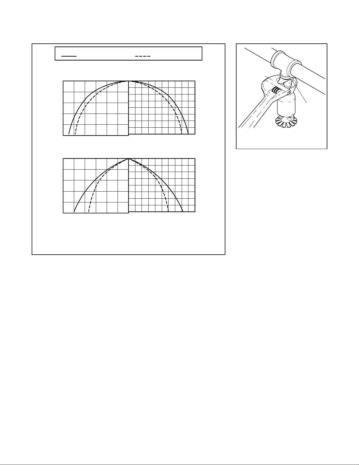
Figure 2 provides the nominal discharge patterns for reference use.
NOTE
The discharge patterns shown in Figure 2 are not to be used for design
purposes or to disregard standard installation rules.
Not l ess tha n two foam-wat er spri nklers are to be installed in any area,
regardless of size, in order to obtain
pattern overlap.
The applied density (flow per unit of
area) of foam solution must meet the
requirements of the Authority Having
Jurisdiction for the type flammable liquidand occupancy.Per NFPA 16,coverage density must not be less than
0.16 GPM/ft2(6,52 mm/min) of floor
area with a resulting minimu m dischargepressure ofnot less than30 psi
(2,1 bar).
Foam-water sprinkler spacing must
not exceed the requirements of NFPA
13 for extra hazard occupancies and
the system must be hydraulically calculated to obtain the required density
and discharge pressure.
NOTE
Discharge outlets and foam concentrates are Listed for use together. Refer to the individual foam concentrate
Listing for operating limitations and
compatibility withthe B-1 Foam-Water
Sprinklers as provided in the UL Fire
Protection Equipment Directory.
Installation
TheModel B-1 Foam-WaterSprinklers
must be installed in accordance with
the following instructions:
NOTE
A leak tight1/2 inchNPT sprinklerjoint
should be obtained with a torque of 7
to 14 ft.lbs. (9,5 to 19,0 Nm). A maximum of 21 ft. lbs. (28,5 Nm) of torque
may be used to install sprinklers with
1/2 NPT connections. Higher levels of
torque may distort the sprinkler inlet
and causeimpairment of the sprinkler.
Step 1. Pendent sprinklers are to be
installed in the pendent position, and
upright sprinklersare to be installedin
the upright position.
Step 2. With pipe thread sealant applied to the pipe threads, hand tighten
the sprinkler into the sprinkler fitting.
Step 3. Tighten the sprinkler into the
sprinkler fitting using an 8 or 10 inch
adjustable Crescent wrench. With reference to Figures 1 and 3, the adjustable Crescent wrench is only to be
applied to the wrench flats of the
wrenching area.
Page 3
TFP840
Page 3 of 4
CEILING, METRES
DISTANCEBELOW
CEILING, METRES
DISTANCEBELOW
0
0,5
1,0
1,5
2,0
2,5
0
0,5
1,0
1,5
2,0
2,5
RADIUS, METRES
RADIUS, METRES
3,0 2,0
DATAKEY
FOAM DISCHARGEWATER DISCHARGE
RADIUS, FEET
024868
UPRIGHT
RADIUS, FEET
01,0 246810
PENDENT
8 OR 10 INCH
101,02,03,0
0
2
4
6
CEILING, FEET
DISTANCEBELOW
ADJUSTABLE
WRENCH
APPLYTO
WRENCH
FLATS
ONLY
FIGURE 3
WRENCH FLATS
0
2
4
6
CEILING, FEET
DISTANCEBELOW
8
FIGURE 2
NOMINAL DISCHARGE PATTERNS
(Shown for reference only — Not suitable for design purposes)
Frequent visual inspections are rec-
Care and
ommendedtobeinitiallyperformedfor
sprinklersinstalled inpotentially corro-
Maintenance
siveatmospheres toverify the integrity
ofthe materialsof constructionas they
TheModel B-1 Foam-WaterSprinklers
must be maintained and serviced in
accordance with the following instructions:
NOTE
Before closinga fire protection system
main control valve for maintenance
work on thefire protection system that
itcontrols, permission toshutdownthe
affectedfire protection systemmustbe
obtained from the proper authorities
and all personnel who may be affected
by this action must be notified.
Model B-1 Foam-Water Sprinklers
must never be painted, plated, coated
or altered in any way after leaving the
factory; otherwise, the spray performance may be impaired.
Care must be exercised to avoid damage to the sprinklers - before, during,
and after installation. Sprinklers damaged by droppin g, s triking, wrench
may be affected by the corrosive conditions present for a given installation.
Thereafter, annual inspections per
NFPA 25 are required.
The owner is responsible for the inspection, testing, and maintenance of
their fire p rotection system and devices in compliance with this document, as well as with the applicable
standards of the National Fire Protection Association (e.g., NFPA 25), in
addition to the standards of any other
authorities having jurisdiction. The installing contractor or sprinkler manufacturer should be contacted relative
to any questions.
It is rec ommen ded that foam-water
sprinkler systems be inspected,
tested, and maintained by a qualified
Inspection Service in accordance with
local requirements and/or national
codes.
twist/slippage, or the like, must be replaced.
Page 4

Page4of4
TFP840
Limited
Warranty
Products manufactured byTyco Fire&
Building Products ( TFBP) ar e warranted solely to the original Buyer for
ten (10) years againstdefects inmaterial and workmanship when paid for
and properly installed and maintained
under normal use and service. This
warranty will expire ten (10) years
from date of shipment by TFBP. No
warranty is given for products or components manufactured by companies
not affiliated by ownership with TFBP
or forproducts and componentswhich
havebeen subject tomisuse,improper
installation, corrosion, or which have
not been installed, maintained, modified orrepaired in accordance with applicable Standards of theNational Fire
Protection Ass ociation, and/or the
standards of any other Authorities
Having Jurisdiction. Materials found
by TFBP to bedefective shall be either
repaired or replaced, at TFBP’s sole
option. TFBP neither assumes, nor
authorizesany persontoassumefor it,
any otherobligation inconnection with
the sale of products or parts of products.TFBP shallnot be responsiblefor
sprinkler systemdesign errorsor inaccurate or incomplete information supplied by Buye r or Buy er’s representatives.
In no event shall TFBP be liable, in
contract, tort, strict liability or under
any other legal theory, for incidental,
indirect,special or consequentialdamages, including but not limited to labor
charges, regardless of whether TFBP
was informed about the possibility of
such damages, and in no event shall
TFBP’s liability exceed an amount
equal to the sales price.
Theforegoingwarrantyismadeinlieu
of any and all other warranties, express or implied, including warranties
ofmerchantabilityand fitnessfor a particular purpose.
This limited warranty sets forth theexclusive remedy for claims based on
failure of or defect in products, materials or components, whether the claim
is made in contract, tort, strict liability
or any other legal theory.
This warranty will apply to the full extent permittedby law. The invalidity, in
whole or part, of any portion of this
warranty will not affect the remainder.
Ordering
Procedure
Whenplacing an order,indicatethefull
product name. Refer to the Price List
for complete listing of Part Numbers.
Contact your local distributor for availability.
Upright Foam-Water Sprinklers:
Specify: Model B-1 Upright FoamWater Sprinkler, P /N 49-210-1-001 .
Pendent Foam-Water Sprinklers:
Specify: Model B-1 Pendent FoamWater Sprinkler, P /N 49-211-1-001 .
TYCO FIRE & BUILDING PRODUCTS,451 North Cannon Avenue, Lansdale, Pennsylvania 19446
 Loading...