

Page 1
Worldwide
Contacts
www.tyco-fire.com
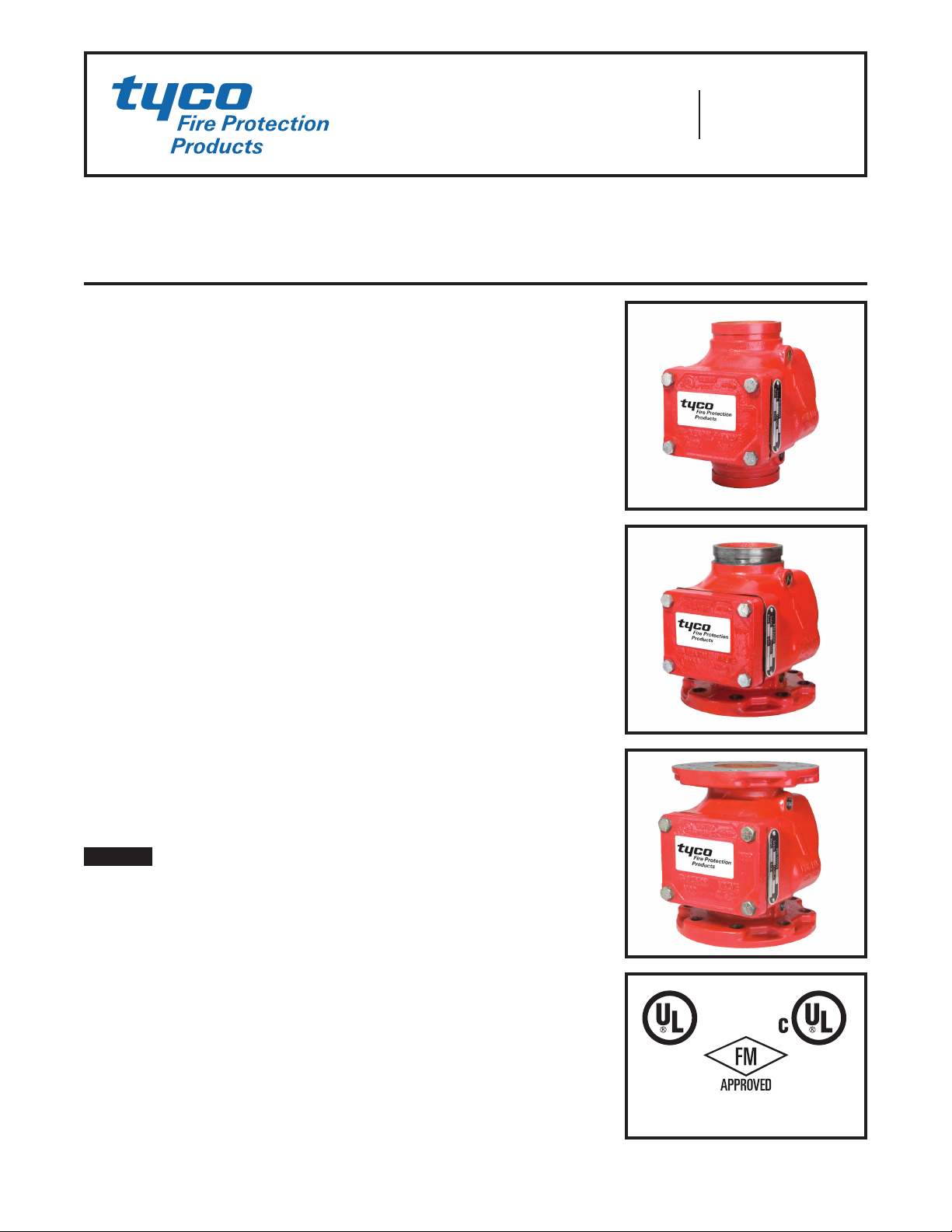
Model AV-1-300 Alarm Check Valve, 300 psi (20,7 bar)
2-1/2, 4, 6 & 8 Inch (DN65, DN100, DN150 & DN200)
Vertical or Horizontal* Installation
General
Description
The TYCO Model AV-1-300 Alarm
Check Valves are divided seat ring,
rubber-faced clapper, waterow alarm
check valves that are intended for
use in wet pipe (automatic sprinkler)
re protection systems. They may be
installed vertically or horizontally*,
and they are designed to automatically actuate electric and/or hydraulic
alarms when there is a steady ow of
water into the system that is equivalent
to the discharge rate of one or more
sprinklers.
A separately ordered Model RC-1
Retard Chamber (Ref. Technical Data
Sheet TFP920) is required for installations subject to variable pressures. It is
used to help prevent false alarms associated with pressure variations in public
water supplies.
The AV-1-300 Alarm Check Valve Trim
includes pressure gauges to monitor
system pressure conditions, a bypass
check valve, a main drain valve, and
an alarm test valve. The bypass check
valve reduces the possibility of false
alarms by permitting slow as well as
small transient increases in water supply pressure to be passed through to
the system without opening the waterway cla p p e r.
NOTICE
The TYCO Model AV-1-300 Alarm
Check Valves described herein must
be installed and maintained in compliance with this document, as well as
with the applicable standards of the
National Fire Protection Association
(NFPA), in addition to the standards of
any authorities having jurisdiction. Failure to do so may impair the integrity of
these devices.
The owner is responsible for maintaining their fire protection system
and devices in proper operating
condition. Contact the installing contractor or product manufacturer with
any questions.
Technical
Data
Approvals
UL and C-UL Listed
FM Approved
Working Water Pressure Range
20 to 300 psi (1,4 to 20,7 bar)
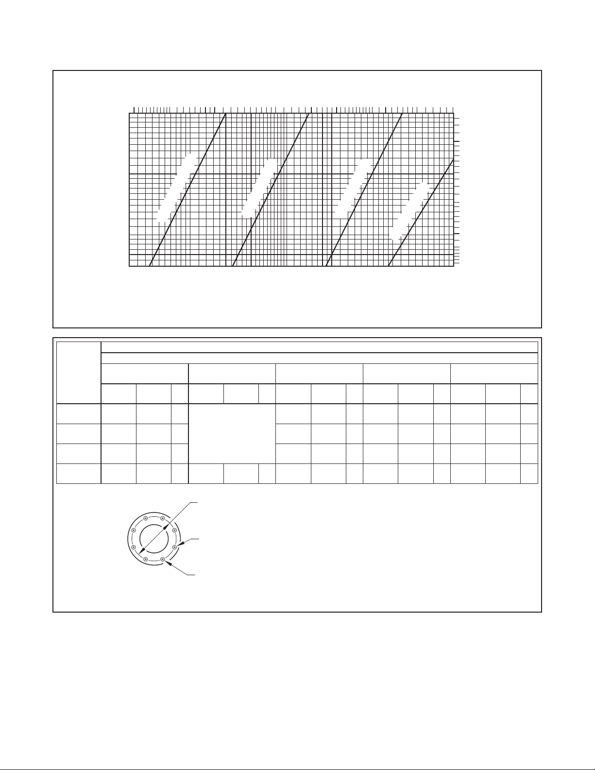
Friction Loss
Refer to Graph A.
End Connections
Groove x Groove
Flange x Groove
Flange x Flange
Refer to Table A for size applicability
Weights
Refer to Table A.
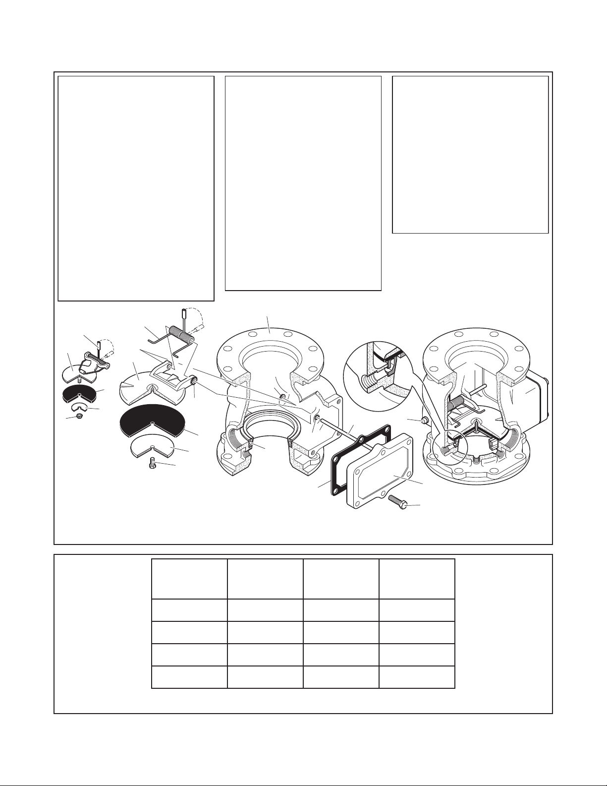
Physical Characteristics
The body is ductile iron, the hand-hole
cover is ductile iron, and the seat ring
is bronze. The clapper for the 2-1/2
inch (DN65) valve size is stainless steel.
The clapper for the larger valve sizes
is ductile iron. All valve sizes utilize an
EPDM clapper facing.
Flanged connections are available
drilled per ANSI, ISO, AS, and JIS
specications as detailed in Table B.
Threaded port connections for the
AV-1-300 Valves are available NPT
threaded or threaded per ISO 7-1 as
detailed in the Ordering Procedure section. Valves with NPT threaded ports
will readily accept the trim arrangements detailed in Figures 4 through 6.
For Fire Pr otecti on pres sure ra ting, li sting
and approval information, contact
your Tyco Representative.
* 4, 6, and 8 inch (DN100, DN150, and DN200) valve sizes
Page 1 of 20 SEPTEMBER 2014 TFP910
Page 2
TFP910
8
VALVES
Page 2 of 20
VALVE PARTS
NO.
DESCRIPTION REF.
1
Valve Body NR
2
Handhole Cover
3
Handhole Cover
. . . . . . . . . .
Gasket
4
Seat Ring NR
Clapper See (b)
5
6
7
8
9
10
11
11
5
. . . . . . . . . .
Clapper Washer
Lock Nut,
2-1/2 Inch Valve See (b)
Self-Locking Hex
Cap Screw, 4, 6, & 8
Inch Valves See (b)
Clapper Hinge
Pin Bushing,
2-1/2 Inch Valve NR
4, 6, & 8 Inch
Valves
. . . . . . . . . . .
QTY.
. . . . . . .
. . .
. . . . . . . .
. . . .
. . .
. . .
. . . . . . .
. .
. . .
. . . .
11
5
1
1
1
1
1
1
1
1
1
1
2
4
1
NR
See (a)
See (a) or (b)Clapper Facing
See (b)
See (b)Clapper Hinge Pin
NR
See (b)Clapper Spring
VALVE PARTS
NO.
DESCRIPTION REF.
Handhole Cover
12
Hex Bolt,
2-1/2 Inch Valve,
1/2-13 UNC-2A
x 1-1/4" Long CH
4 Inch Valve,
1/2-13 UNC-2A
x 1-3/4" Long CH
6 Inch Valve,
1/2-13 UNC-2A
x 1-3/4" Long CH
8 Inch Valve,
3/4-10 UNC-2A
x 2" Long CH
13
Clapper Hinge Pin
Square Head Pipe
Plug, 3/8" NPT,
4, 6, & 8 Inch
Valves only CH
1
. . . . .
. . . . .
. . . . .
. . . . . . . . .
. . . . . . .
QTY.
4
4
6
6
1
REPLACEMENT PARTS
NO.
DESCRIPTION P/N
(a)
Repair Parts Kit,
Includes 3 & 6
2-1/2 Inch Valve
4 Inch Valve
6 Inch Valve
8 Inch Valve
(b)
Clapper Assembly,
Includes 5-9, 11
2-1/2 Inch Valve
Includes 5-11
4 Inch Valve
6 Inch Valve
8 Inch Valve
NOTES:
1.
2.
3.
. . . . . . . . .
. . . . . . . . .
. . . . . . . . .
. . . . . . . . .
. . . . . . . . .
. . . . . . . . .
F x F valve shown for reference;
components for G x G and F x G
valves are shared.
NR: Not Replaceable
CH: Common Hardware
. . . . . .
. . . . . .
92-200-1-216
92-200-1-416
92-200-1-620
92-200-1-816
92-200-1-218
92-200-1-423
92-200-1-623
92-200-1-823
10
9
10
4
3
13
2
12
CLAPPER
ASSEMBLY
2-1/2 INCH
VALVE
6
7
10
6
7
8
CLAPPER
ASSEMBLY
4, 6, & 8 INCH
FIGURE 1
2-1/2, 4, 6 & 8 INCH (DN65, DN100, DN150 & DN200)
MODEL AV-1-300 ALARM CHECK VALVE ASSEMBLY
Nominal
Valve Size,
Inches
(DN)
2-1/ 2
(65)
4
(100)
6
(150 )
8
(200)
Groove x Groove,
Lbs.
(kg)
22
(10,0)
38
(17, 2 )
58
(26,3)
102
(46,3)
TABLE A
Flange x Groove,
Lbs.
(kg)
28
(12,7 )
47
(21, 3)
70
(31, 8)
120
(54,4)
Flange x Flange,
Lbs.
(kg)
N/A
57
(25,9)
84
(38,1)
149
(67, 6 )
AVAILABLE VALVE END CONNECTIONS AND VALVE WEIGHTS
Page 3
FLOW RATE IN LITRES PER MINUTE (LPM)
FLOW RATE IN GALLONS PER MINUTE (GPM)
NOMINAL PRESSURE DROP
4.0
(1 PSI = 0,06895 BAR)
Bolt Holes
600400 1000
(1 GPM = 3,785 LPM)
2000
TFP910
Page 3 of 20
1000050003000 7000 15000
Nominal
Valve
Size
2-1/2 Inch
(DN65)
4 Inch
(DN100)
6 Inch
(DN150)
8 Inch
(DN200)
3.0
0,20
2.0
0,10
2-1/2 INCH (DN65)
1.0
0.9
IN POUNDS PER SQUARE INCH (PSI)
0.8
0.7
200100
300
4 INCH (DN100)
500400
6 INCH (DN150)
8 INCH (DN200)
3000700 1000 2000 4000
0,09
0,08
0,07
0,06
0,05
GRAPH A
2-1/2, 4, 6 & 8 INCH (DN65, DN100, DN150 & DN200) MODEL AV-1-300 ALARM CHECK VALVE
NOMINAL PRESSURE LOSS VERSUS FLOW
Flange Drilling Specication
Nominal Dimensions in Inches and (mm)
ANSI B16.1
(Class 125)
1
ISO 2084
(PN10)
2 3
ISO 2084
(PN16)
JIS B 2210
(10K)
Dim.ADim.BQty. Dim.ADim.BQty. Dim.ADim.BQty. Dim.ADim.BQty. Dim.
5.50
(139,7)
7.50
(190,5)
9.50
(241,3)
11.75
(298,5)
0.75
(19,0)
0.75
(19,0)
0.88
(22,2)
0.88
(22,2)
4
USE
8
ISO 2084
(PN16)
8
11.61
8 8
(295,0)
0.87
(22,0)
Dim. A
Bolt Circle
Diameter
12
5.51
4
(140,0)
6.89
8
(175,0)
9.45
8
(240,0)
11.42
(290,0)
0.75
(19,0)
0.75
(19,0)
0.91
(23,0)
0.91
(23,0)
4
8
8
12
5.71
(145,0)
7.09
(180,0)
9.45
(240,0)
11.61
(295,0)
1
Same drilling as for B16.5 (Class 150) and B16.42 (Class 250).
2
Same drilling as for BS 4504 Section 3.2 (PN10) and DIN 2532 (PN10).
3
Same drilling as for BS 4504 Section 3.2 (PN16) and DIN 2532 (PN16).
0.71
(18,0)
0.71
(18,0)
0.87
(22,0)
0.87
(22,0)
Dim. B
Bolt Hole
Diameter
Qty. N
Number of
AS 2129
(Table E)
A
5.00
(127,0)
7.00
(178,0)
9.25
(235,0)
11.50
(292,0)
NOMINAL PRESSURE DROP IN BAR
Dim.BQty.
0.71
(18,0)
0.71
(18,0)
0.87
(22,0)
0.87
(22,0)
4
8
8
8
FLANGE DRILLING SPECIFICATIONS
TABLE B
Page 4
TFP910
WATERFLOW
RESTRICTION
ALARM PORT
PRESSURE
PRESSURE
SCREEN
DRAIN RESTRICTION
WITH 0.125" (3,2 mm)
ORIFICE
INLET RESTRICTION
WITH 0.219" (5,6 mm)
ORIFICE
Page 4 of 20
Operation
When the re protection system is initially pressurized, water ows into the
system until the water supply and system pressure become equalized, and
the torsion Spring closes the Waterway Clapper in the Alarm Check Valve.
Once the pressures stabilize, the Alarm
Check Valve is in service and the centrally located groove in the Seat Ring is
sealed. Consequently, with the Alarm
Check Valve set for service, there is
no ow through the alarm port to the
alarm devices (i.e., water motor alarm
and/or pressure alarm switch).
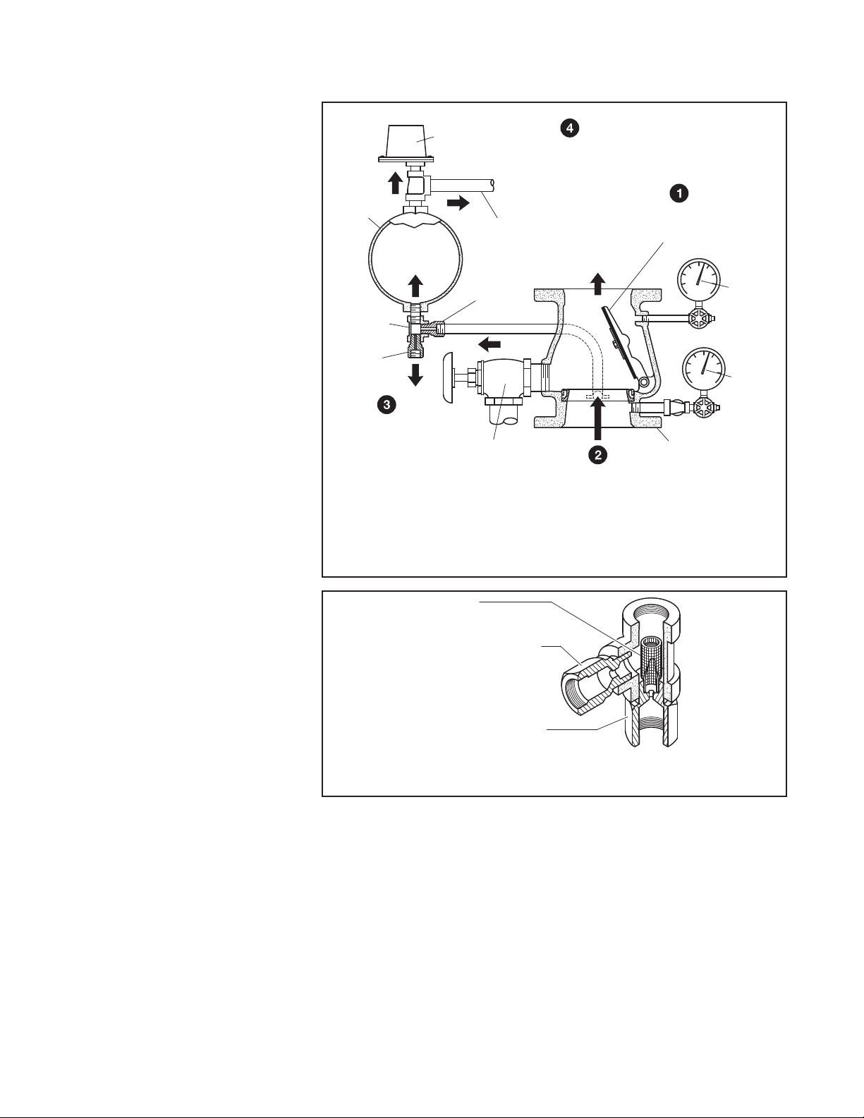
When there is a steady ow of water
into the sprinkler system due to a sprinkler operation, the Waterway Clapper
opens as shown in Figure 2. Water is
then permitted to ow into the centrally
located groove in the Seat Ring and
out through the alarm port towards the
Restriction Assembly (Figure 3). When
the ow through the Inlet Restriction of
the Restriction Assembly exceeds the
ow through the Outlet Restriction, the
Retard Chamber (where provided for
systems with variable pressure), begins
to ll.
Subsequently, the Water Motor Alarm
and/or the pressure alarm switch will
be actuated. The alarms will continue
to be actuated as long as the Waterway Clapper remains open. Water in
the alarm lines will automatically drain
out through the 1/8 inch (3,2 mm) Drain
Orice in the Restriction Assembly
(Figure 3) when the Waterway Clapper closes (due to a stop in the ow of
water into the sprinkler system).
For variable pressure systems, slow
as well as small transient increases in
water supply pressure may continue to
build up in the system (via the Bypass
Check Valve) without opening the
Waterway Clapper.
A transient surge in supply pressure that is sufcient only to open the
Waterway Clapper momentarily will not
cause a false alarm, and a portion of
the increase in pressure will be trapped
within the system, thus reducing the
possibility of another opening. Any
water in the alarm line is automatically
drained, further reducing the possibility of a false alarm due to a successive
transient surge in supply pressure.
Design
Criteria
In planning installation of the TYCO
Model AV-1-300 Alarm Check Valves,
consideration must be given to the disposal of the large quantities of water
that may be associated with draining
the system or performing a ow test.
PRESSURE
RETARD
CHAMBER
ASSEMBLY
1/8"
(3,2 mm)
ORIFICE
OUTLET
WHEN FLOW THROUGH
RESTRICTION ASSEMBLY
INLET EXCEEDS OUTLET,
RETARD CHAMBER
BEGINS TO FILL
ALARM SWITCH
WATERFLOW
TO WATER
MOTOR ALARM
7/32"
(5,6 mm)
ORIFICE
INLET
MAIN
DRAIN
VALVE
ONCE RETARD
CHAMBER OVERFLOWS,
WATERFLOW PRESSURE
ALARM SWITCH AND
WATER MOTOR
ALARM ACTUATE
FIGURE 2
2-1/2, 4, 6 & 8 INCH (DN65, DN100, DN150 & DN200)
MODEL AV-1-300 ALARM CHECK VALVE
OPERATION
FIGURE 3
RESTRICTION ASSEMBLY
(Provided with Alarm Check Valve Trim)
Valves installed in the vertical position
must have the ow going up. Valves
installed in the horizontal position must
be positioned so that the drain connection points down.
The sprinkler system designer must
be aware that the conguration of
the piping network and its tendency
to trap pockets of air (such as in the
case of a peaked-roof gridded system) can affect the performance of the
alarm system. Although a slight amount
of trapped air is desirable to prevent
signicant pressure increases due to
thermally induced expansion of the
water, a large quantity of trapped air in
a system may result in the possibility of
an intermittent alarm.
UPON SPRINKLER
FLOW, WATERWAY
CLAPPER OPENS
WATERFLOW
TO SYSTEM
SYSTEM
GAUGE
SUPPLY
GAUGE
ALARM
CHECK
WATERFLOW
THROUGH SEAT
RING GROOVE AND
VALVE
The possibility of an intermittent alarm
condition is a consequence of the fact
that the ow out of the system through
the test valve or a single sprinkler is
very small relative to the ow that can
be passed through the valve. This difference increases with valve size. If the
system were free of trapped air, ow in
would equal ow out and the Waterway
Clapper would always stabilize at some
open position (as needed to accommodate the required ow). With trapped
air in the system, however, the Waterway Clapper rst opens wider since the
system initially demands greater ow
until the air pockets are compressed
(back to nearly the supply pressure),
and then it will tend to return closer
Page 5

TFP910
Page 5 of 20
to the Seat Ring. If the volume of the
air pockets is excessive, ow into the
system can be momentarily reduced
to nearly zero (once the air pockets
are compressed) and the Waterway
Clapper may close, causing ow to the
alarms to be shutoff.
After the Waterway Clapper has
closed, sufcient water must ow out
of the system before the Waterway
Clapper will again open. A repetition
of the above described condition is
termed an intermittent alarm.
Using a vent (which can also serve
as an end-of-line Inspector’s Test
Connection) piped from the top of a
cross main or end of a branch line at
the point most remote from the alarm
valve, and lling the system slowly in
accordance with the steps described in
the Setting Procedure section, can prevent an excessive amount of air from
being trapped.
Installation
NOTICE
Proper operation of the TYCO Model
AV-1-300 Alarm Check Valves depends
upon the trim described in this data
sheet installed in accordance with the
following instructions. Failure to follow the appropriate trim installation
instructions may prevent the device
from functioning properly as well as
void listings/approvals and the manufacturer’s warranties.
The Alarm Check Valves must be
installed in readily visible and accessible locations.
It is recommended that provision be
made for viewing the alarm line drain
water by locating the main drain outlet
in a readily visible area.
Wet pipe fire protection systems must
be maintained at a minimum temperature of 40°F (4°C).
Step 1. Trim the Alarm Check Valve in
accordance with Figure 4, 5, or 6, as
applicable. Apply pipe-thread sealant
sparingly to male threads only.
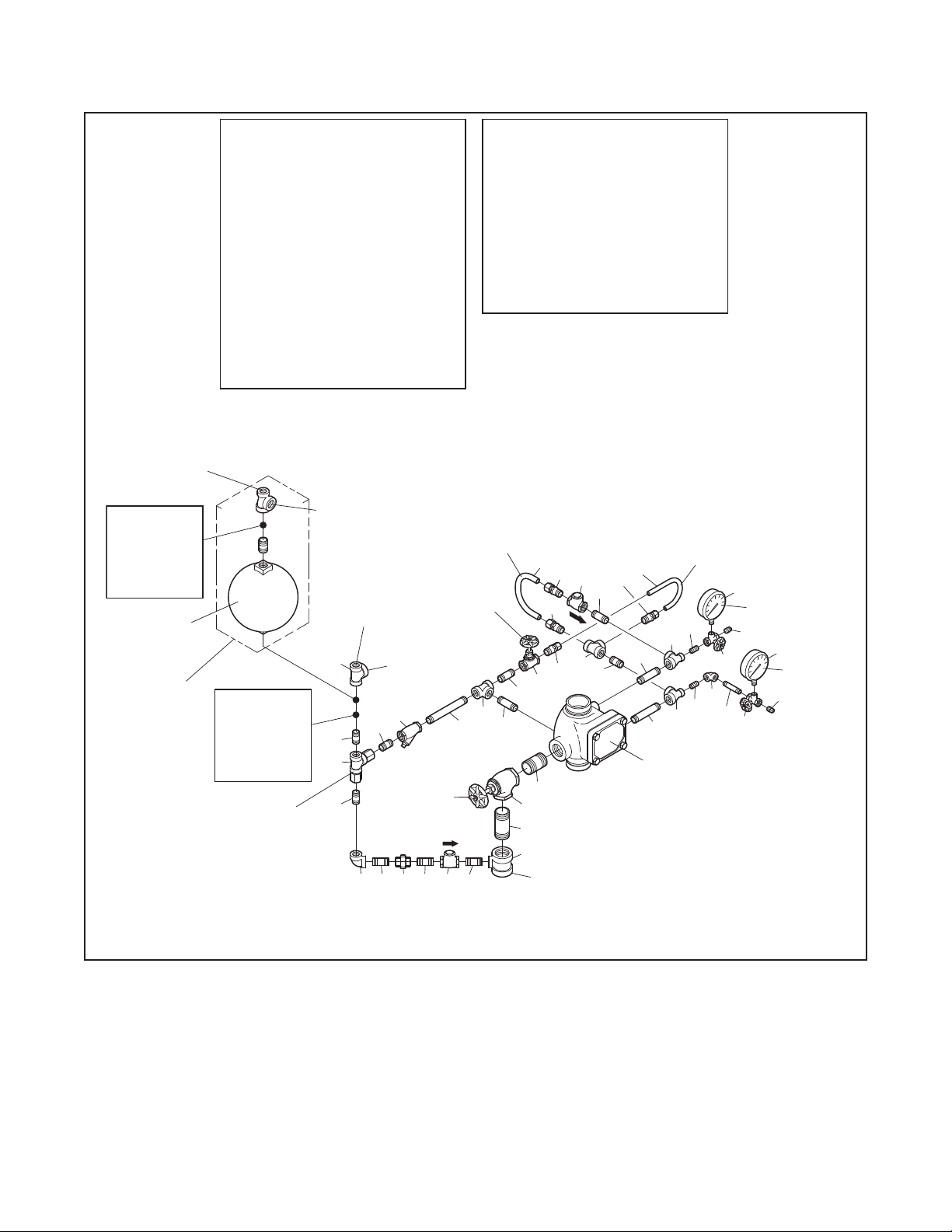
Step 2. The Alarm Vent Trim illustrated
in Figure 8 must be installed if a water
motor alarm is not to be used.
Step 3. Plug unused alarm
connections.
Step 4. Suitable provision must be
made for disposal of alarm line and
system drainage water. Drainage
water must be directed so that it will
not cause damage or result in dangerous conditions.
Step 5. The alarm line drain must be
arranged so that there will be no danger of freezing.
Step 6. The check valve in the externally mounted bypass around the
Waterway Clapper must be installed
with its arrow pointed up, and the drain
check valve must be installed with its
arrow pointing towards the drain.
Step 7. It is recommended that a vent
connection (which may also be used
as an end-of-line Inspector’s Test
Connection), be piped from a cross
main or branch line at the point most
remote from the alarm valve. The vent
line should be connected to the top of
a cross main or to the end of a branch
line and be located at the highest level
of a multi-level installation.
The vent connection can be used to
bleed-off excessive air from the system, and therefore, minimize the
possibility of a false alarm due to a
transient surge in supply pressure. The
contraction/expansion associated with
an excessive amount of trapped air
could also cause the Waterway Clapper to cycle open and shut during an
inspector’s test or during a discharge
by a single sprinkler.
Setting
Procedure
Steps 1 through 11 are to be performed
when initially setting the Model AV-1300 Alarm Check Valve or after system
operation due to a re.
NOTICE
Filling the system with water will result
in operation of the associated alarms.
Consequently, notification must first be
given to the owner and fire department,
central station, or other signal station to
which the alarms are connected.
Notify the proper authorities and all
personnel who may be affected that
an alarm test is to be performed.
After placing a fire protection system
in service, notify the proper authorities
and advise those responsible for monitoring proprietary and/or central station
alarms.
Step 1. Open the 1/4 inch Gauge Test
Valves for the Supply and System Pressure Gauges.
Step 2. Check to see that the Handhole Cover bolts are tight. If not,
cross-tighten them.
Step 3. Close the Alarm Test Valve.
Step 4. Open the remote cross main or
branch line vent connection. (Refer to
Step 7 in the Installation section.)
Step 5. Slowly open the main control
valve until the sound of owing water
just begins and then open the valve
one more turn.
Step 6. Close the remote branchline
vent connection after the discharge of
aerated water ceases, and the outlet
has owed full for at least 15 seconds.
Step 7. Fully open the main control
valve.
Step 8. Open the end-of-line Inspector’s Test Connection (or Alarm Test
Valve, if acceptable to the authority
having jurisdiction) and verify that the
system alarms operate.
Step 9. Close the end-of-line Inspector’s Test Connection (or Alarm Test
Valve).
Step 10. Verify that water ceases to
ow from the alarm line drain. If water
continues to ow, follow the corrective
procedure described in the Care and
Maintenance section.
The Restriction Assembly has a 1/8
inch (3,2 mm) diameter drain orice.
Sufcient time must be allowed for
drainage of the Retard Chamber and
the piping to the water motor alarm.
Step 11. After verication that the ow
of water out of the alarm line drain has
stopped, the alarm valve is set and is
ready for service.
Page 6
TFP910
TO DRAIN
PRESSURE ALARM
PRESSURE
Page 6 of 20
1/2 INCH NPT
CONNECTION
FOR WATERFLOW
SWITCH
LOCATION
FOR OPTIONAL
ELECTRICALLY
SUPERVISED
N.O. ALARM
CONTROL
VALVE
MODEL RC-1
RETARD
CHAMBER
ORDERED
SEPARATELY
(FOR VARIABLE
PRESSURE
SYSTEMS)
NO.
DESCRIPTION P/N
1
300 psi/ 2000 kPa
Water Pressure Gauge
2
1/4" Gauge Test Valve
3
1/2" Swing Check Valve
4
1/2" Globe Valve 46-047-1-004
5
1/2" Y-Strainer 52-353-1-005
6
Restriction Assembly
7
1-1/4" Angle Valve
8
External By-Pass Tube
9
Alarm Test Tube
10
1/2" NPT x 1/2" Tube
Connector
11
1/2" NPT x 5/8" Tube
Connector
12
1/4" Plug
13
1/2" Union
14
1/4" 90° Elbow
15
1/2" 90° Elbow
16
1/2" Tee CH
LOCATION
FOR OPTIONAL
ELECTRICALLY
SUPERVISED
N.O. ALARM
CONTROL
VALVE
RESTRICTION
ASSEMBLY,
SEE FIGURE 3
. . . . . . . . . . . .
. . . . . . . . . . . .
. . . . . . . . . . . . .
. . . . . . . . . . . .
. . . . . . . . . . . . . .
QTY.
2
. .
92-343-1-005
2
. .
46-005-1-002
2
.
46-049-1-004
1
. . . . . . .
. . . . . . . . .
. . . . . . . . .
. . . . . . . . .
CONNECTION FOR
FOR WATERFLOW
PRESSURE ALARM
18
22
22
1
1
. . . .
. . . . . .
1
. .
1
. . . . . . .
1
2
2
2
1
1
1
2
3/4 INCH NPT
WATER MOTOR
ALARM
1/2 INCH NPT
CONNECTION
SWITCH
CONNECTION FOR
WATER MOTOR
5
22
6
DRAIN VALVE
(NORMALLY
CLOSED)
15 13
22 22
92-210-2-005
46-048-1-007
92-304-1-017
92-304-1-047
CH
CH
CH
CH
CH
CH
3/4 INCH NPT
ALARM
MAIN
NO.
NOTES:
1.
2.
EXTERNAL
BY-PASS
TUBE
ALARM
TEST VALVE
(NORMALLY
CLOSED)
16
3
22
DESCRIPTION
17
18
1/2" x 1/2" x 3/4" Tee CH
19
20
21
1/4" x 2-1/2" Nipple CH
22
23
1/2" x 2" Nipple CH
24
25
1/2" x 3" Nipple
26
1/2" x 4" Nipple
27
28
1-1/4" x 2-1/2" Nipple CH
29
1-1/4" x 3-1/2" Nipple CH
All Fittings and Nipples are galvanized
(Standard Order).
CH: Common Hardware.
8
11
3
11
16
10
4
23
2427
28
7
29
19
1-1/4 INCH NPT
CONNECTION
QTY.
. . . .
2
. . . .
1
. . . . . . . .
. . . . . . . .
. . . . . . . .
. . . . . . . .
. . . . . . . .
22
1
2
. . . . .
1
. . . . .
7
2
. . . . .
1
1
1
1
. . . .
1
. . . .
1
9
10
23
25
2-1/2 INCH (DN65)
GROOVE x GROOVE
26
MODEL AV-1
ALARM VALVE,
P/N
CH1/2" x 1/4" x 1/2" Tee
CH1-1/4" x 1-1/4" x 1/2" Tee
CH1/4" x 1" Nipple
CH1/2" x 1-1/2" Nipple
CH1/2" x 2-1/2" Nipple
CH
CH
CH1/2" x 6" Nipple
TEST TUBE
20
17
17
SHOWN
ALARM
14
20
2
21
1
SYSTEM
PRESSURE
GAUGE
12
2
1
12
SUPPLY
GAUGE
FIGURE 4 (1 OF 3)
VERTICAL CLOSED DRAIN TRIM — STANDARD ORDER
FOR 2-1/2 INCH (DN65) MODEL AV-1-300 ALARM CHECK VALVES (P/N 52-204-4-950)
Page 7

P/N
TO DRAIN
PRESSURE
PRESSURE
DESCRIPTION
NO.
300 psi/ 2000 kPa
1
Water Pressure Gauge
1/4" Gauge Test Valve
2
1/2" Swing Check Valve
3
4
1/2" Globe Valve
1/2" Y-Strainer
5
6
Restriction Assembly 92-210-2-005
7
2" Angle Valve
8
1/4" Plug
9
1/2" x 1/4" Reducing
Bushing
10
1/2" Union
1/2" 90° Elbow
11
1/2" 45° Elbow
12
1/2" x 1/4" x 1/2" Tee
13
1/2" x 1/2" x 3/4" Tee
14
1/2" Tee
15
2" x 2" x 1/2" Tee
16
17
18
1/4" x 4" Nipple
1/2" x Close Nipple
19
1/2" x 1-1/2" Nipple
20
21
1/2" x 2" Nipple
. . . . . . . . . . . . .
. . . . . . . . . . . . . .
. . . . . . . . . . . .
. . . . . . . . . . . . . .
QTY. QTY.
92-343-1-005
2
. .
46-005-1-002
2
. .
46-049-1-004
2
.
46-047-1-004
1
. . . . . . .
. . . . . . . . .
. . . . . . . . .
. . . . . . . . .
. . . . . . . . .
. . . . . . .
. . . . .
. . . . . . . .
. . . . .
. . . . .
. . . . . . . .
. . . .
. . . .
. . . .
52-353-1-005
1
1
46-048-1-009
1
CH
2
CH
1
CH
3
CH
4
1
CH
1
CH
CH
1
1
CH
1
CH
1
CH1/4" x Close Nipple
CH
1
4
CH
5
CH
2
CH
NO.
DESCRIPTION
. . . . .
. . . . .
. . . . .
. .
. .
2
1
1
1
1
2
2
2
6 Inch (DN150)
1/2" x 2-1/2"
1/2" x 4-1/2"
22
1/2" x 3" Nipple
1/2" x 3-1/2" Nipple
23
24
1/2" x 5" Nipple
25
1/2" x 5-1/2" Nipple
1/2" x 6-1/2" Nipple
26
27
Select Nipple per Table
28
Select Nipple per Table
29
Nipple
Number
27
28
NOTES:
Install subassemblies in alphabetical order.
1.
All Fittings and Nipples are galvanized
2.
(Standard Order).
3.
CH: Common Hardware.
. . . . . . . .
. . . . . . . .
. . . . . . . . . .
Select Appropriate Nipple Sizes
per AV-1 Alarm Check Valve Size
4 Inch (DN100)
1/2" x 1-1/2"
1/2" x 3-1/2"
TFP910
Page 7 of 20
P/N
CH
CH
CH
CH
CH
CH
CH
CH2" x 3" Nipple
1/2 INCH NPT
CONNECTION
FOR WATERFLOW
PRESSURE ALARM
SWITCH
LOCATION
FOR OPTIONAL
ELECTRICALLY
SUPERVISED
N.O. ALARM
CONTROL
VALVE
MODEL RC-1
RETARD
CHAMBER
ORDERED
SEPARATELY
(FOR VARIABLE
PRESSURE
SYSTEMS)
LOCATION
FOR OPTIONAL
ELECTRICALLY
SUPERVISED
N.O. ALARM
CONTROL
VALVE
RESTRICTION
ASSEMBLY,
SEE FIGURE 3
3/4 INCH NPT
CONNECTION FOR
WATER MOTOR
ALARM
1/2 INCH NPT
CONNECTION
FOR WATERFLOW
PRESSURE ALARM
SWITCH
14
20
M
10
11
(4 INCH VALVE)
(6 INCH VALVE)
3/4 INCH NPT
CONNECTION FOR
WATER MOTOR
ALARM
15
26
5
19
H
12
22
L
6
19
11
20
A
21
B
C
N
1919 203
1/2" x 1-1/2"
or
1/2" x 2-1/2"
27
25
20
10
11
7
K
I
G
3 20
24
29
16
ALARM
TEST VALVE
(NORMALLY
CLOSED)
11
21
23
10
J
29
MAIN
DRAIN VALVE
(NORMALLY
CLOSED)
2 INCH NPT
CONNECTION
1/2" x 3-1/2"
(4 INCH VALVE)
1/2" x 4-1/2"
(6 INCH VALVE)
4
28
or
9
F
22
MODEL AV-1
ALARM VALVE,
6 INCH (DN150)
FLANGE xFLANGE
SHOWN
1
1
13
FIGURE 4 (2 OF 3)
VERTICAL CLOSED DRAIN TRIM — STANDARD ORDER — SEMI-PREASSEMBLED
FOR 4 & 6 INCH (DN100 & DN150) MODEL AV-1-300 ALARM CHECK VALVES (P/N 52-204-4-951)
SYSTEM
GAUGE
8
2
E
18
SUPPLY
GAUGE
8
2
D
17
Page 8

TFP910
TO DRAIN
PRESSURE
Page 8 of 20
1/2 INCH NPT
CONNECTION
FOR WATERFLOW
PRESSURE ALARM
SWITCH
LOCATION
FOR OPTIONAL
ELECTRICALLY
SUPERVISED
N.O. ALARM
CONTROL
VALVE
MODEL RC-1
RETARD
CHAMBER
ORDERED
SEPARATELY
(FOR VARIABLE
PRESSURE
SYSTEMS)
DESCRIPTION
NO.
300 psi/ 2000 kPa
1
Water Pressure Gauge
1/4" Gauge Test Valve
2
1/2" Swing Check Valve
3
3/4" Swing Check Valve
4
1/2" Globe Valve
5
6 28
1/2" Y-Strainer 52-353-1-005
Restriction Assembly
7
2" Angle Valve
8
1/4" Plug
9
1/2" Union
10
11
3/4" Union
12
1/2" 90° Elbow
13
1/2" 45° Elbow
1/2" Tee
14
15
3/4" x 1/4" x 3/4" Tee
16
17
3/4" x 3/4" x 1/2" Tee
2" x 2" x 1/2" Tee
18
1/4" x 1-1/2" Nipple
19
1/2" x Close Nipple
20
1/2" x 1-1/2" Nipple
21
LOCATION
FOR OPTIONAL
ELECTRICALLY
SUPERVISED
N.O. ALARM
CONTROL
VALVE
RESTRICTION
ASSEMBLY,
SEE FIGURE 3
. . . . . . . . . . . . .
. . . . . . . . . . . .
. . . . . . . . . . . .
. . . . . . . . . . . . . .
3/4 INCH NPT
CONNECTION FOR
WATER MOTOR
ALARM
FOR WATERFLOW
PRESSURE ALARM
15
21
QTY. QTY.
P/N
2
. .
92-343-1-005
2
. .
46-005-1-002
1
.
46-049-1-004
1
.
46-049-1-005
1
. . . . . . .
. . . . . . . . .
. . . . . . . . .
. . . . . . . . .
. . . . . . . . .
. . . . . . .
. . . . .
. . . . .
. . . . .
1/2 INCH NPT
CONNECTION
SWITCH
10
46-047-1-004
1
1
92-210-2-005
1
46-048-1-009
2
CH
2
CH
1
CH
2
CH
1
CH
1
CH
CH1/2" x 1/2" x 3/4" Tee
1
. . . .
2
. . . .
CH
1
. . . .
CH
1
CH
2
CH
3
CH
3
CH
3/4 INCH NPT
CONNECTION FOR
WATER MOTOR
ALARM
14
26
6
20
13
3201220
21
DRAIN VALVE
(NORMALLY
23
7
21
MAIN
CLOSED)
NO.
DESCRIPTION
. . . . . . . . . .
ALARM
CLOSED)
5
25
. . . . . . . .
. . . . . . . .
. . . . .
. . . . .
. . . . .
. . . . .
. . . . .
. . . . .. . . .
. . . . . . . .
. . . . .
. . . . . . .
1/2" x 2" Nipple
22
23
1/2" x 3" Nipple
24
1/2" x 3-1/2" Nipple
25
1/2" x 4-1/2" Nipple
26
1/2" x 6-1/2" Nipple
27
3/4" x Close Nipple
3/4" x 1-1/2" Nipple
3/4" x 2-1/2" Nipple CH
29
3/4" x 3" Nipple
30
3/4" x 4-1/2" Nipple
31
2" x 3" Nipple
32
2" x 3-1/2" Nipple
33
NOTES:
Install subassemblies in alphabetical order.
1.
All Fittings and Nipples are galvanized
2.
(Standard Order).
3.
CH: Common Hardware.
TEST VALVE
(NORMALLY
12
22
24
10
24
25
8
32
33
18
2 INCH NPT
CONNECTION
P/N
1
CH
1
CH
2
CH
2
CH
1
CH
2
CH
1
CH
1
CH
1
CH
1
CH
1
CH
1
27
11
29
30
17
MODEL AV-1
ALARM VALVE,
8 INCH (DN200)
FLANGE x GROOVE
SHOWN
SYSTEM
PRESSURE
GAUGE
19
16
31
28
9
2
27
4
9
2
19
16
1
1
SUPPLY
GAUGE
FIGURE 4 (3 OF 3)
VERTICAL CLOSED DRAIN TRIM — STANDARD ORDER — SEMI-PREASSEMBLED
FOR 8 INCH (DN200) MODEL AV-1-300 ALARM CHECK VALVES (P/N 52-204-4-952)
Page 9

TFP910
BAR
PRESSURE ALARM
PRESSURE
TO DRAIN
TO DRAIN
Page 9 of 20
1/2 INCH NPT
CONNECTION
FOR WATERFLOW
SWITCH
LOCATION
FOR OPTIONAL
ELECTRICALLY
SUPERVISED
N.O. ALARM
CONTROL
VALVE
MODEL RC-1
RETARD
CHAMBER
ORDERED
SEPARATELY
(FOR VARIABLE
PRESSURE
SYSTEMS)
DESCRIPTION
NO.
300 psi/ 2000 kPa
1
Water Pressure Gauge
2
1/4" Gauge Test Valve
1/2" Swing Check Valve
3
1/2" Globe Valve
4
1/2" Y-Strainer 52-353-1-005
5
Restriction Assembly
6
1-1/4" Angle Valve
7
External By-Pass Tube
8
9
Alarm Test Tube
1/2" NPT x 1/2" Tube
10
Connector
1/2" NPT x 5/8" Tube
11
Connector
Support Bar
12
Jam Nut
13
PVC Nipple
14
Support Bracket
15
Drip Funnel
16
1/4" Plug CH
17
LOCATION
FOR OPTIONAL
ELECTRICALLY
SUPERVISED
N.O. ALARM
CONTROL
VALVE
RESTRICTION
ASSEMBLY,
SEE FIGURE 3
. . . . . . . . . . . .
. . . . . . . . . . . .
. . . . . . . . . . .
. . . . . . . . . . . . . .
. . . . . . . . . . .
. . . . . . . . . . .
. . . . . . . . . . . . .
1-1/4 INCH NPT
CONNECTION
QTY.
P/N
. .
2
92-343-1-005
2
. .
46-005-1-002
46-049-1-004
1
.
1
1
1
. . . .
1
1
. .
1
2
2
1
1
1
1
1
2
ALARM
SWITCH
CONNECTION FOR
25
31
22
46-047-1-004
92-210-2-005
46-048-1-007
92-304-1-017
92-304-1-047
CH
CH
92-304-1-014
92-640-1-037
92-640-1-009
92-343-1-006
92-343-1-007
5
. . . . . . .
. . . . . . . . .
. . . . . .
. . . . . . .
. . . . . . . .
3/4 INCH NPT
CONNECTION FOR
WATER MOTOR
1/2 INCH NPT
CONNECTION
FOR WATERFLOW
PRESSURE ALARM
21
25
6
SUPPORT
BRACKET
DRIP
FUNNEL
WATER MOTOR
ALARM
TEST VALVE
(NORMALLY
CLOSED)
3/4 INCH NPT
ALARM
13
14
15
16
12
SUPPORT
DESCRIPTION
NO.
1/4" 90° Elbow
18
19
1/2" Tee CH
20
1/2" x 1/4" x 1/2" Tee
21
1/2" x 1/2" x 3/4" Tee
22
1-1/4" x 1-1/4" x 1/2" Tee
23
1/4" x 1" Nipple
24
1/4" x 2-1/2" Nipple
25
1/2" x 1-1/2" Nipple
26
1/2" x 2" Nipple
1/2" x 2-1/2" Nipple
27
1/2" x 3" Nipple
28
1/2" x 4" Nipple
29
1/2" x 5" Nipple
30
31
1-1/4" x 2-1/2" Nipple
32
1-1/4" x 8-1/2" Nipple
NOTES:
All Fittings and Nipples are galvanized
1.
(Standard Order).
CH: Common Hardware.
2.
EXTERNAL
BY-PASS
TUBE
26
19
30
27
31
7
32
22
1-1/4 INCH NPT
. . . . . . . . .
. . . . . . . . . . . . . .
8
11
3
11
19
10 25
4
MAIN
DRAIN VALVE
(NORMALLY
CLOSED)
CONNECTION
QTY.
1
2
2
. . . .
1
. . . .
2
. . . . . . . .
. . . . . . . .
. . . . . . . .
. . . . . . . .
. . . . . . . .
2
1
. . . . .
3
. . . . .
2
1
. . . . .
1
1
1
2
. . . .
1
. . . .
9
10
26
28
2-1/2 INCH (DN65)
GROOVE x GROOVE
P/N
CH
CH
CH
CH
CH
CH
CH
CH
CH
CH
CH
CH
CH
CH
ALARM
TEST TUBE
23
20
23
20
29
MODEL AV-1
ALARM VALVE,
SHOWN
18
2
24
1
SYSTEM
PRESSURE
GAUGE
17
2
1
17
SUPPLY
GAUGE
FIGURE 5 (1 OF 3)
VERTICAL OPEN DRAIN TRIM — SPECIAL ORDER
FOR 2-1/2 INCH (DN65) MODEL AV-1-300 ALARM CHECK VALVES (P/N 52-204-4-053)
Page 10

TFP910
TO DRAIN
PRESSURE
PRESSURE
Page 10 of 20
. . . . .
. . . . . . . .
. . . . . . . .
. . . . .
. . . . . . . .
. . . . .
. . . . .
(4 INCH VALVE)
(6 INCH VALVE)
4
30
QTY.
P/N
4
CH
2
CH
1
CH
1
CH
1
CH
1
CH
1
CH
2
. .
CHSelect Nipple per Table
2
. .
CH
1
6 Inch (DN150)
1/2" x 2-1/2"
1/2" x 4-1/2"
1/2" x 3-1/2"
or
1/2" x 4-1/2"
F
6 INCH (DN150)
FLANGE xFLANGE
1
12
1
24
16
MODEL AV-1
ALARM VALVE,
SHOWN
1/2 INCH NPT
CONNECTION
FOR WATERFLOW
PRESSURE ALARM
SWITCH
LOCATION
FOR OPTIONAL
ELECTRICALLY
SUPERVISED
N.O. ALARM
CONTROL
VALVE
MODEL RC-1
RETARD
CHAMBER
ORDERED
SEPARATELY
(FOR VARIABLE
PRESSURE
SYSTEMS)
NO.
DESCRIPTION
1
300 psi/ 2000 kPa
Water Pressure Gauge
2
1/4" Gauge Test Valve
3
1/2" Swing Check Valve
4
1/2" Globe Valve
5
1/2" Y-Strainer
6
7
2" Angle Valve
8
Drip Funnel Connector
9
Drip Funnel Bracket
10
Drip Funnel
11
1/4" Plug
12
1/2" x 1/4" Reducing
Bushing
13
1/2" Union
14
1/2" 90° Elbow
15
1/2" 45° Elbow
16
1/2" x 1/4" x 1/2" Tee
17
1/2" x 1/2" x 3/4" Tee CH
18
1/2" Tee
19
1/4" x Close Nipple
20
1/4" x 4" Nipple
21
1/2" x Close Nipple
CONNECTION FOR
LOCATION
FOR OPTIONAL
ELECTRICALLY
SUPERVISED
N.O. ALARM
CONTROL
VALVE
RESTRICTION
ASSEMBLY,
SEE FIGURE 3
1-1/4 INCH NPT
CONNECTION
. . . . . . .
. . . . . . . . .
. . . . . . . . .
. . . . . . . . . . .
. . . . . . . . . . . . .
. . . . . . . . . . . . . .
. . . . . . . . . . . .
. . . . . . . . .
. . . . . . . . .
. . . . . . . . . . . . . .
. . . . . . . .
3/4 INCH NPT
WATER MOTOR
ALARM
1/2 INCH NPT
CONNECTION
FOR WATERFLOW
PRESSURE ALARM
17
18
22
6
K
TO DRAIN
QTY.
P/N
2
. .
92-343-1-005
2
. .
46-005-1-002
1
.
46-049-1-004
1
46-047-1-004
1
52-353-1-005
1
. . . .
92-210-2-005Restriction Assembly
1
46-048-1-009
. .
1
92-211-1-005
1
92-211-1-003
. . . .
1
92-343-1-007
2
CH
1
CH
2
CH
3
CH
1
CH
1
CH
. . . .
1
. . . .
2
CH
1
. . . . .
. . . . .
SWITCH
CH
1
CH
3
CH
3/4 INCH NPT
CONNECTION FOR
WATER MOTOR
21
15
21
21
8
10
9
DRIP
FUNNEL
ALARM
28
5
H
1/2" x 1-1/2"
(4 INCH VALVE)
1/2" x 2-1/2"
(6 INCH VALVE)
18
22
14
22
A
23
B
14
7
C
NO.
DESCRIPTION
22
1/2" x 1-1/2" Nipple
23
1/2" x 2" Nipple
24
1/2" x 3" Nipple
25
1/2" x 3-1/2" Nipple
26
1/2" x 5" Nipple
27
1/2" x 5-1/2" Nipple
28
1/2" x 6-1/2" Nipple
29
30
Select Nipple per Table
31
2" x 3" Nipple CH
Nipple
Number
29 1/2" x 1-1/2"
30 1/2" x 3-1/2"
NOTES:
Install subassemblies in alphabetical order.
1.
All Fittings and Nipples are galvanized
2.
(Standard Order).
3.
CH: Common Hardware.
or
23
29
I
27
. . . . . . . . . .
Select Appropriate Nipple Sizes
per AV-1 Alarm Check Valve Size
4 Inch (DN100)
ALARM
TEST VALVE
(NORMALLY
CLOSED)
14
25
13
J
G
3
22
13
26
31
MAIN
DRAIN VALVE
(NORMALLY
CLOSED)
2 INCH NPT
CONNECTION
FIGURE 5 (2 OF 3)
VERTICAL OPEN DRAIN TRIM — SPECIAL ORDER — SEMI-PREASSEMBLED
FOR 4 & 6 INCH (DN100 & DN150) MODEL AV-1-300 ALARM CHECK VALVES (P/N 52-204-4-954)
SYSTEM
GAUGE
11
2
E
20
SUPPLY
GAUGE
11
2
D
19
Page 11

TFP910
TO DRAIN
PRESSURE
Page 11 of 20
1/2 INCH NPT
CONNECTION
FOR WATERFLOW
PRESSURE ALARM
SWITCH
LOCATION
FOR OPTIONAL
ELECTRICALLY
SUPERVISED
N.O. ALARM
CONTROL
VALVE
MODEL RC-1
RETARD
CHAMBER
ORDERED
SEPARATELY
(FOR VARIABLE
PRESSURE
SYSTEMS)
DESCRIPTION
NO.
300 psi/ 2000 kPa
1
Water Pressure Gauge
1/4" Gauge Test Valve
2
3/4" Swing Check Valve
3
1/2" Globe Valve
4
1/2" Y-Strainer
5
6
2" Angle Valve
7
Drip Funnel Connector
8
Drip Funnel Bracket
9
Drip Funnel
10
1/4" Plug
11
1/2" Union
12
3/4" Union
13
1/2" 90° Elbow
14
1/2" 45° Elbow
15
1/2" Tee
16
17
3/4" x 1/4" x 3/4" Tee
18
3/4" x 3/4" x 1/2" Tee
19
CONNECTION FOR
LOCATION
FOR OPTIONAL
ELECTRICALLY
SUPERVISED
N.O. ALARM
CONTROL
VALVE
RESTRICTION
ASSEMBLY,
SEE FIGURE 3
1-1/4 INCH NPT
CONNECTION
. . . . . . .
. . . . . . . . .
. . . . . . . . .
. . . . . . . . . . .
. . . . . . . . . . . . .
. . . . . . . . . . . .
. . . . . . . . . . . .
. . . . . . . . .
. . . . . . . . .
. . . . . . . . . . . . . .
3/4 INCH NPT
WATER MOTOR
ALARM
1/2 INCH NPT
CONNECTION
FOR WATERFLOW
PRESSURE ALARM
SWITCH
17
16
22
6
H
P/N
QTY.
92-343-1-005
2
. .
46-005-1-002
2
. .
46-049-1-005
1
.
46-047-1-004
1
52-353-1-005
1
1
. . . .
92-210-2-005Restriction Assembly
46-048-1-009
1
. .
92-211-1-005
1
92-211-1-003
1
. . . .
92-343-1-007
1
CH
2
CH
1
CH
1
CH
1
CH
1
CH
2
CH1/2" x 1/2" x 3/4" Tee
1
. . . .
2
. . . .
CH
1
CH
. . . .
3/4 INCH NPT
CONNECTION FOR
WATER MOTOR
ALARM
26
5
21
E
15
DRAIN VALVE
21
9
DRIP
(NORMALLY
A
21
8
10
FUNNEL
16
MAIN
CLOSED)
7
DESCRIPTION
NO.
1/4" x 1-1/2" Nipple
20
1/2" x Close Nipple
21
1/2" x 1-1/2" Nipple CH
22
1/2" x 2" Nipple
23
1/2" x 3-1/2" Nipple
24
1/2" x 4-1/2" Nipple
25
1/2" x 6-1/2" Nipple
26
3/4" x Close Nipple
27
28
3/4" x 1-1/2" Nipple CH
3/4" x 2-1/2" Nipple
29
3/4" x 3" Nipple
30
3/4" x 4-1/2" Nipple
31
2" x 3" Nipple
32
NOTES:
Install subassemblies in alphabetical order.
1.
All Fittings and Nipples are galvanized
2.
(Standard Order).
3.
CH: Common Hardware.
ALARM
TEST VALVE
(NORMALLY
CLOSED)
14
23
. . . . .
. . . . .
. . . . .
. . . . . . . .
. . . . .
. . . . .
. . . . .
. . . . .
. . . . .
. . . . .
. . . . . . . .
. . . . .
. . . . . . . . . .
G
F
24
4
12
24
25
D
2 INCH NPT
CONNECTION
TO DRAIN
25
32
P/N
QTY.
2
CH
3
CH
1
CH
1
CH
2
CH
2
CH
1
CH
2
1
CH
1
CH
1
CH
1
CH
1
C
13
30
MODEL AV-1
ALARM VALVE,
8 INCH (DN200)
FLANGE x GROOVE
B
27
29
31
19
SHOWN
SYSTEM
PRESSURE
GAUGE
20
18
28
11
2
27
3
11
2
20
18
1
1
SUPPLY
GAUGE
FIGURE 5 (3 OF 3)
VERTICAL OPEN DRAIN TRIM — SPECIAL ORDER — SEMI-PREASSEMBLED
FOR 8 INCH (DN200) MODEL AV-1-300 ALARM CHECK VALVES (P/N 52-204-4-955)
Page 12

TFP910
TO DRAIN
FOR WATERFLOW
FLANGE x FLANGE
Page 12 of 20
DESCRIPTION
NO.
300 psi/ 2000 kPa
1
Water Pressure Gauge
1/4" Gauge Test Valve
2
1/2" Swing Check Valve
3
1/2" Globe Valve
4
1/2" Y-Strainer
5
Restriction Assembly
6
2" Globe Valve
7
1/4" Plug
8
1/2" Union
9
1/2" 90° Elbow
10
1/2" x 1/4" x 1/2" Tee
11
12
1/2" x 1/2" x 3/4" Tee
. . . . . . . . . . . . . .
1/2" Tee
13
2" x 2" x 1/2" Tee
14
1/4" x Close Nipple
15
16
1/4" x 4" Nipple
1/2" x 1-1/2" Nipple
17
1/2" x 2" Nipple
18
19
1/2" x 3" Nipple
20
1/2" x 3-1/2" Nipple
3/4 INCH NPT
CONNECTION
FOR WATER
MOTOR
ALARM
LOCATION
FOR OPTIONAL
ELECTRICALLY
SUPERVISED
N.O. ALARM
CONTROL
VALVE
1/2 INCH NPT
CONNECTION
PRESSURE
ALARM
SWITCH
3/4 INCH NPT
CONNECTION
FOR WATER
MOTOR
ALARM
LOCATION
FOR OPTIONAL
ELECTRICALLY
SUPERVISED
N.O. ALARM
CONTROL
VALVE
RESTRICTION
ASSEMBLY,
SEE FIGURE 3
. . . . . . .
. . . . . . . . .
. . . .
. . . . . . . . .
. . . . . . . . . . . . .
. . . . . . . . . . . .
. . . . . . . . .
. . . .
. . . .
. . . . . . .
. . . . .
. . . . . . . .
. . . . .
. . . . . . . .
. . . . . . . .
. . . . .
1/2 INCH NPT
CONNECTION
FOR WATERFLOW
PRESSURE
ALARM SWITCH
12
17
6
17
17
10
QTY.
P/N
2
. .
92-343-1-005
. .
2
46-005-1-002
2
.
46-049-1-004
1
46-047-1-004
1
52-353-1-005
1
92-210-2-005
1
46-047-1-009
2
CH
3
CH
5
CH
1
CH
1
CH
1
CH
1
CH
1
CH
1
CH
8
CH
3
CH
2
CH
1
CH
1/2" x 1-1/2"
(4 INCH
VALVE)
or
1/2" x 2-1/2"
(6 INCH
VALVE)
1/2" x 7"
(4 INCH
VALVE)
or
1/2" x 8"
(6 INCH
VALVE)
18
19
9
5
17
ORDERED
SEPARATELY
(FOR VARIABLE
PRESSURE
SYSTEMS)
MODEL RC-1
RETARD
CHAMBER
10
18
9
23
13
25
10
10
DESCRIPTION P/N
NO.
1/2" x 5" Nipple
21
1/2" x 5-1/2" Nipple
22
Select Nipple per Table
23
Select Nipple per Table
24
25
2" x 2-1/2" Nipple CH
26
Nipple
Number
23
24
25
NOTES:
All Fittings and Nipples are galvanized
1.
(Standard Order).
CH: Common Hardware.
2.
ALARM
TEST VALVE
(NORMALLY
CLOSED)
4
20
1/2" x 3-1/2"
(4 INCH
VALVE)
or
1/2" x 4-1/2"
(6 INCH
VALVE)
22
17
3
17
17
9
18
10
. . . . . . . .
. . . . .
. . . . . . .
Select Appropriate Nipple Sizes
per AV-1 Alarm Check Valve Size
4 Inch (DN100)
1/2" x 1-1/2"
1/2" x 3-1/2"
1/2" x 7"
SYSTEM
PRESSURE
GAUGE
1
8
24
21
16
26
7
26
14
17
3
2
8
19
CONNECTION
QTY.
1
CH
1
CH
. .
2
CH
. .
2
CH
. .
2
CHSelect Nipple per Table
2
6 Inch (DN150)
1/2" x 2-1/2"
1/2" x 4-1/2"
1/2" x 8"
15
11
2 INCH NPT
HANDHOLE
COVER MUST
BE AT LEAST
AWAY FROM
MODEL AV-1
ALARM VALVE,
6 INCH (DN150)
DRAIN VALVE
(NORMALLY
SUPPLY
PRESSURE
GAUGE
1
2
30 INCHES
A WALL
SHOWN
MAIN
CLOSED)
FIGURE 6 (1 OF 2)
HORIZONTAL CLOSED DRAIN TRIM — SPECIAL ORDER
FOR 4 & 6 INCH (DN100 & DN150) MODEL AV-1-300 ALARM CHECK VALVES (P/N 52-204-4-057)
Page 13

TFP910
TO DRAIN
FOR WATERFLOW
Page 13 of 20
DESCRIPTION
NO.
300 psi/ 2000 kPa
1
Water Pressure Gauge
1/4" Gauge Test Valve
2
1/2" Swing Check Valve
3
3/4" Swing Check Valve
4
1/2" Globe Valve
5
1/2" Y-Strainer
6
Restriction Assembly
7
2" Globe Valve 2" x 2-1/2" Nipple
8
1/4" Plug
9
1/2" Union
10
3/4" Union
11
1/2" 90° Elbow
12
1/2" Tee
13
1/2" x 1/2" x 3/4" Tee
14
3/4" x 1/4" x 3/4" Tee
15
3/4" x 3/4" x 1/2" Tee
16
2" x 2" x 1/2" Tee
17
1/4" x 1-1/2" Nipple
18
1/2" x 1-1/2" Nipple
19
1/2" x 2" Nipple
20
1/2" x 3" Nipple
21
3/4 INCH NPT
CONNECTION
FOR WATER
MOTOR
ALARM
LOCATION
FOR OPTIONAL
ELECTRICALLY
SUPERVISED
N.O. ALARM
CONTROL
VALVE
1/2 INCH NPT
CONNECTION
PRESSURE
ALARM
SWITCH
3/4 INCH NPT
CONNECTION
FOR WATER
MOTOR
ALARM
LOCATION
FOR OPTIONAL
ELECTRICALLY
SUPERVISED
N.O. ALARM
CONTROL
VALVE
. . . . . . .
. . . . . . . . .
. . . . . . . . .
. . . . . . . . . . . . .
. . . . . . . . . . . .
. . . . . . . . . . . .
. . . . . . . . .
. . . . . . . . . . . . . .
. . . . . . .
. . . . .
. . . . .
. . . . . . . .
. . . . . . . .
1/2 INCH NPT
CONNECTION
FOR WATERFLOW
PRESSURE
ALARM SWITCH
14
19
7
19
P/N
QTY.
92-343-1-005
. .
2
46-005-1-002
. .
2
46-049-1-004
.
1
46-049-1-005
.
1
46-047-1-004
1
52-353-1-005
1
92-210-2-005
. . . .
1
46-047-1-009
1
CH
2
CH
2
CH
1
CH
3
CH
1
. . . .
CH
1
CH
. . . .
2
. . . .
CH
1
CH
1
CH
2
CH
5
CH
2
CH
1
RESTRICTION
ASSEMBLY,
SEE FIGURE 3
20
21
ORDERED
SEPARATELY
(FOR VARIABLE
PRESSURE
SYSTEMS)
MODEL RC-1
RETARD
CHAMBER
22
12
20
10
22
13
24
TEST VALVE
(NORMALLY
DESCRIPTION
NO.
1/2" x 3-1/2" Nipple
22
1/2" x 4-1/2" Nipple
23
1/2" x 9-1/2" Nipple
24
3/4" x Close Nipple
25
3/4" x 1-1/2" Nipple
26
3/4" x 2-1/2" Nipple
27
3/4" x 3" Nipple
28
3/4" x 4-1/2" Nipple
29
30
2" x 3" Nipple
31
NOTES:
All Fittings and Nipples are galvanized
1.
(Standard Order).
CH: Common Hardware.
2.
1
9
18
15
25
11
27
5
ALARM
CLOSED)
23
MAIN
DRAIN VALVE
(NORMALLY
CLOSED)
23
PRESSURE
2
25
4
. . . . .
. . . . .
. . . . .
. . . . .
. . . . .
. . . . .
. . . . . . . .
. . . . .
. . . . . . .
. . . . . . . . . .
SYSTEM
GAUGE
1
9
29
26
16
28
31
P/N
QTY.
CH
2
CH
2
CH
1
CH
2
CH
1
CH
1
CH
1
CH
1
CH
1
CH
1
PRESSURE
18
15
COVER MUST
BE AT LEAST
MODEL AV-1
ALARM VALVE,
8 INCH (DN200)
8
30
17
SUPPLY
GAUGE
2
HANDHOLE
30 INCHES
AWAY FROM
A WALL
FLANGE x
GROOVE
SHOWN
10
19
6
12
19
12
19
3
2 INCH NPT
CONNECTION
FIGURE 6 (2 OF 2)
HORIZONTAL CLOSED DRAIN TRIM — SPECIAL ORDER
FOR 8 INCH (DN200) MODEL AV-1-300 ALARM CHECK VALVES (P/N 52-204-4-058)
Page 14

TFP910
ELEVATION VIEW
Page 14 of 20
C
F
G
BA
PLAN VIEW
RC-1
ELEVATION VIEW
D
G x G &
F x G
Vertical Closed Drain Trim
Dimension
A
B
C
D
E
E
F
G
Dimensions in Inches and (mm)
With RC-1
16-1/2 (419)
10-1/2 (267)
10-1/2 (267)
8-7/8 (225)
12-1/4 (311)
16-1/2 (419)
3 (75)
Without RC-1
13-1/2 (343)
10-1/2 (267)
10 (254)
8-7/8 (225)
12-1/4 (311)
N/A
3 (75)
C
Vertical Open Drain Trim
Dimension
A B
PLAN VIEW
RC-1
F
G
D
G x G &
F x G
E
A
B
C
D
E
F
G
Dimensions in Inches and (mm)
With RC-1
8-7/8 (225) 8-7/8 (225)
16-1/2 (419)
Without RC-1
13-1/2 (343)15-1/2 (394)
10-1/2 (267)10-1/2 (267)
10 (254)10-1/2 (267)
12-1/4 (311)12-1/4 (311)
N/A
3 (75)3 (75)
FIGURE 7 (1 OF 3)
INSTALLATION DIMENSIONS
FOR 2-1/2 INCH (DN65) MODEL AV-1-300 ALARM CHECK VALVES
Page 15

TFP910
Page 15 of 20
C
Dimension
4 Inch (DN100)
A B
PLAN VIEW
RC-1
F
G
ELEVATION VIEW
A B
PLAN VIEW
RC-1
F
G
E
D
C
E
D
A
B
C
D (G x G)
D (F x F)
D (F x G)
E
F
G
Dimension
A
B
C
D (G x G)
D (F x F)
D (F x G)
E
F
G
19 (483)
10-1/2 (267)
10-1/2 (267)
10-1/4 (260)
10 (254)
10 (254)
12-1/2 (318)
15-1/2 (394)
3 (75)
4 Inch (DN100)
19 (483)
10-1/2 (267)
10-1/2 (267)
10-1/4 (260)
10 (254)
10 (254)
12-1/2 (318)
15-1/2 (394)
Vertical Closed Drain Trim
Dimensions in Inches and (mm)
6 Inch (DN150) 4 Inch (DN100)
19 (483)
11-1/4 (286)
11-1/2 (292)
12-1/4 (311)
12 (305)
12 (305)
15 (381)
15-1/2 (394)
2-3/4 (70)
Vertical Open Drain Trim
Dimensions in Inches and (mm)
With RC-1
6 Inch (DN150)
19 (483)
11-1/4 (286)
11-1/2 (292)
12-1/4 (311)
12 (305)
12 (305)
15 (381)
15-1/2 (394)
2-3/4 (70)3 (75)
Without RC-1With RC-1
19 (483)
10-1/2 (267)
10-1/2 (267)
10-1/4 (260)
10 (254)
10 (254)
12-1/2 (318)
11-1/2 (292)
3 (75)
Without RC-1
4 Inch (DN100)
19 (483)
10-1/2 (267)
10-1/2 (267)
10-1/4 (260)
10 (254)
10 (254)
12-1/2 (318)
11-1/2 (292)
3 (75)
6 Inch (DN150)
19 (483)
11-1/4 (286)
11-1/2 (292)
12-1/4 (311)
12 (305)
12 (305)
15 (381)
11-1/2 (292)
2-3/4 (70)
6 Inch (DN150)
19 (483)
11-1/4 (286)
11-1/2 (292)
12-1/4 (311)
12 (305)
12 (305)
15 (381)
11-1/2 (292)
2-3/4 (70)
ELEVATION VIEW
RC-1
D
B
E
C A
ELEVATION VIEW PLAN VIEW
FOR 4 & 6 INCH (DN100 & DN150) MODEL AV-1-300 ALARM CHECK VALVES
Horizontal Closed Drain Trim
Dimension
A (G x G)
A (F x F)
A (F x G)
B
C
D
E
4 Inch (DN100)
10-1/4 (260)
13-3/4 (349)
With RC-1
10 (254)
10 (254)
15 (381)
3-1/4 (83)
14 (356)
FIGURE 7 (2 OF 3)
INSTALLATION DIMENSIONS
Dimensions in Inches and (mm)
Without RC-1
6 Inch (DN150)
12-1/4 (311)
12 (305)
12 (305)
15 (381)
3-1/4 (83)
15 (381)
14-3/4 (375)
4 Inch (DN100)
10-1/4 (260)
10 (254)
10 (254)
10-1/2 (267)
3-1/4 (83)
14 (356)
13-3/4 (349)
6 Inch (DN150)
12-1/4 (311)
12 (305)
12 (305)
11-1/2 (292)
3-1/4 (83)
15 (381)
14-3/4 (375)
Page 16

TFP910
Page 16 of 20
RC-1
F
G
PLAN VIEW
ELEVATION VIEW
C
Vertical Closed Drain Trim
Dimension
D
BA
F x F
F x G &
G x G
E
C
A
B
C
D
E
F
G
Dimensions in Inches and (mm)
With RC-1
18-1/2 (470) 15-3/4 (400)
16-1/8 (410) 16-1/8 (410)
12 (305) 12 (305)
16-1/2 (419) 16-1/2 (419)
15-1/2 (394)
2-1/2 (64) 2-1/2 (64)
Without RC-1
14 (356)14 (356)
N/A
A B
PLAN VIEW
RC-1
F
G
ELEVATION VIEW
D
B
E
C
ELEVATION VIEW PLAN VIEW
FOR 8 INCH (DN200) MODEL AV-1-300 ALARM CHECK VALVES
Dimension
D
F x F
F x G &
G x G
E
RC-1
Dimension
A
F x F
F x G &
G x G
FIGURE 7 (3 OF 3)
INSTALLATION DIMENSIONS
Vertical Open Drain Trim
Dimensions in Inches and (mm)
With RC-1
A
B
C
D
E
F
G
A
B
C
D
E
18-1/2 (470)
16-1/8 (410)
12 (305)
14 (356)
16-1/2 (419)
15-1/2 (394)
3-1/2 (89)
Horizontal Closed Drain Trim
Dimensions in Inches and (mm)
With RC-1
14 (356)
15 (381)
1-1/2 (38)
19-1/2 (495)
Without RC-1
15-3/4 (400)
16-1/8 (410)
12 (305)
14 (356)
16-1/2 (419)
N/A
3-1/2 (89)
Without RC-1
14 (356)
12 (305)
N/A
19-1/2 (495)
16-1/2 (419)16-1/2 (419)
Page 17

TFP910
CHAMBER
(ROUTE TO
Page 17 of 20
. . . . . . . . .
PRESSURE
SWITCH
2
(GREEN
TINT)
QTY.
1
1
1
1
CH
92-032-1-002
3
DRAIN)
NO.
DESCRIPTION P/N
1
3/4" x 1/4" Hex
Bushing
2
3/32" Vent
. . . . . . . . . . .
Fitting
3
1/4" x 5'-0"
. . . . . . . . . .
Tubing CH
MODEL RC-1
RETARD
Trim kit is ordered separately when a
Water Motor Alarm is not installed.
FIGURE 8
ALARM VENT TRIM KIT
(P/N 52-201-2-012)
Care and
Maintenance
The following procedures and
inspections should be performed in
accordance with this section, in addition to any specic requirements of the
NFPA. Any impairment must be immediately corrected.
NOTICE
Performing the care and maintenance
procedures will result in operation of
the associated alarms. Consequently,
notification must first be given to the
owner and fire department, central station, or other signal station to which the
alarms are connected.
Before closing a fire protection system
main control valve for maintenance
work on the fire protection system
that it controls, obtain permission to
shut down the affected fire protection
system from the proper authorities
and notify all personnel who may be
affected by this decision.
The owner is responsible for the
inspection, testing, and maintenance of
their re protection system and devices
in compliance with this document, as
well as with the applicable standards
of the National Fire Protection Association (e.g., NFPA 25), in addition to
the standards of any other authorities
having jurisdiction. Contact the installing contractor or product manufacturer
regarding any questions.
Automatic sprinkler systems are recommended to be inspected, tested,
and maintained by a qualied Inspection Service in accordance with local
requirements and/or national codes.
The TYCO Model AV-1-300 Alarm
Check Valves do not require any regularly scheduled maintenance. It is
recommended, however, that proper
operation of the alarms be periodically
veried in accordance with a procedure that is acceptable to the authority
having jurisdiction. Any impairment
must be immediately corrected.
Inspection Procedure
It is recommended that the following
inspection procedure be performed at
least quarterly by a qualied Inspection
Service.
Step 1. Notify the proper authorities
and all personnel who may be affected
that an alarm test is to be performed.
Step 2. Open the end-of-line Inspector’s Test Connection (or Alarm Test
Valve, if acceptable to the authority
having jurisdiction) and verify that the
system alarms operate in accordance
with the requirements of the authority
having jurisdiction. Verify that the water
motor alarm and/or the pressure alarm
switch properly actuate and within the
elapsed time required by the authority
having jurisdiction.
Step 3. Verify that water is owing
out of the alarm line drain at a rate
consistent with the 1/8 inch (3,2 mm)
diameter drain orice in the Restriction
As s embl y.
Step 4. Close the end-of-line Inspector’s Test Connection (or Alarm Test
Valve).
Step 5. Verify that water ceases to ow
from the alarm line drain.
Step 6. Clean the 1/2 inch Strainer
(located in the valve trim) as well as
the 3/4 inch Strainer (located at the
connection to the water motor alarm,
as applicable). Be sure to replace the
strainer baskets and tighten the caps
securely.
NOTICE
Cleaning of the Strainers after each
operation of the alarms is especially
important in the case of water supplies (such as lakes and rivers) having
a large quantity of suspended matter. A
clogged alarm line can prevent operation of the alarms.
Step 7. Notify all authorities responsible for monitoring the installation that
the re protection system has been
returned to service.
Sprinkler System Drain-Down
Draining the sprinkler system must be
done in accordance with the following
procedure:
Step 1. Close the main control valve, if
this has not already been done.
Step 2. Open the remote cross main or
branch line vent connection. (Refer to
Step 7 in the Installation section.)
Step 3. Open the Main Drain Valve.
Check rst to see that the drainage
water discharge will not cause damage or result in dangerous conditions.
Step 4. Wait until the Supply Pressure
Gauge reads zero pressure and the
sound of draining water has stopped
before performing any maintenance
work on the re protection system.
Leakage from Alarm Line Drain
Follow the steps indicated below until
water ceases to ow from the alarm
line drain. After each step check if leakage has stopped.
Step 1. Open the Main Drain Valve. Let
the water ow for about 5 seconds and
then close the Main Drain Valve. This
should ush any loose debris that may
have become trapped between the
Clapper Facing and the Seat Ring or
in the seating area of the Drain Valve.
Step 2. Repeat Step 1 if the rate of
continued ow out of the drain was
noticeably reduced.
Step 3. Open the Alarm Test Valve and
allow water to ow for about 5 seconds
before re-closing the valve. This should
ush any loose debris that may have
become trapped in the seating area of
the Alarm Test Valve.
Step 4. Repeat Step 3 if the rate of
continued ow out of the drain was
noticeably reduced.
Step 5. Determine whether the water is
owing from the Alarm Port (Ref. Figure
1) or past the Alarm Test Valve. If the
leakage is past the Alarm Test Valve,
close the main control valve, and then
repair or replace the Alarm Test Valve
as necessary.
Step 6. If it appears that the leakage
noted in Step 5 is from the Alarm Port,
drain the system in accordance with
the prescribed procedure. After the
system has been drained, remove the
Handhole Cover.
Step 7. While holding the Spring down
by the coils, remove the Hinge Pin.
Remove the Spring and Waterway
Clapper Assembly.
Page 18

TFP910
Page 18 of 20
Step 8. Using a light, check for and
remove any debris that may have
become lodged within the Seat Ring
groove. Inspect the Seat Ring seat
for any damage. If the Seat Ring has
become dented across the seat then
the Alarm Check Valve will have to be
replaced. It is impractical to re-face a
Seat Ring in the eld.
Step 9. Check for and remove any
debris that may have become lodged
in the Clapper Facing. If a minor imperfection remains in the Clapper Facing,
then turn it over after thoroughly cleaning both surfaces with a clean cloth.
Replace the Clapper Facing if necessary. Be sure to securely re-tighten
the retaining fastener for the Clapper
Washer.
Step 10. Replace the Spring and
Waterway Clapper Assembly as shown
in Figure 1. While holding the coils of
the Spring down, re-insert the Hinge
Pin. Be sure that the Hinge Pin is
pushed all the way to the rear of the
valve.
Step 11. Replace the Handhole Cover.
Return the Alarm Valve to operation in
accordance with the steps described in
the Setting Procedure section.
Clogged Alarm Line Drain
If water either does not ow or only
dribbles out of the alarm line drain during an alarm test, then it is likely that
the screen protecting the Restriction
Assembly drain orice (Ref. Figure 3)
has become clogged.
NOTICE
For variable pressure systems, a
clogged alarm line drain will increase
the likelihood of a false alarm.
First break the union downstream of
the Drain Restriction and remove the
Drain Restriction for cleaning by backushing the screen. Re-install the Drain
Restriction and re-assemble the drain
line.
Loss of Excess System Pressure
For variable pressure systems, the
System Pressure Gauge normally indicates a pressure greater than that
shown by the Supply Pressure Gauge.
Also, the value should be close to that
of the peak supply pressure that has
occurred after the system was placed
in service.
NOTICE
For variable pressure systems, loss of
excess system pressure will increase
the likelihood of a false alarm.
Follow the procedure indicated below
to correct a loss of excess system
pressure condition.
Step 1. Check for signs of continued
leakage from the alarm line drain. If rust
stains and/or water deposits indicate
that continued leakage has been taking
place, take corrective action according
to the procedure described in the subsection entitled “Leakage from Alarm
Line Drain.”
Step 2. If there are no signs of continued leakage from the alarm line drain,
close the main control valve, slowly
remove the plug from the supply pressure gauge test valve to relieve the
supply pressure, and then slowly open
the union in the externally mounted
bypass.
Step 3. Check for leakage past the
Bypass Check Valve. If there is leakage, debris may have become lodged
between its clapper and seat. Drain
the system in accordance with the
prescribed procedure and then clean
or replace the Bypass Check Valve as
required.
Step 4. Re-assemble the externally
mounted bypass, replace the plug into
the Gauge Test Valve, and return the
re protection system to operation in
accordance with the steps described
in the Operation section.
Step 5. If there are no signs of leakage past either the Alarm Check Valve
Clapper per Step 1 or the Bypass
Check Valve per Step 2, inspect the
sprinkler system for leakage.
Excess Pressure Due to
Thermal Expansion
Wet pipe sprinkler systems subject
to ambient temperatures in excess of
100°F (38°C) can experience signicant
increases in system pressure due to
the thermal expansion of the water. In
particular, a gridded wet-pipe system
with a relatively small air pocket and
no relief valve can be subjected to an
increase of more than 100 psi (6,9 bar),
due to an increase in ambient temperature of approximately 50°F (28°C).
As necessary, install a pressure
relief valve, in accordance with the
requirements of the authority having
jurisdiction, to automatically relieve
the excess pressure that could otherwise be created in wet-pipe systems
exposed to signicant increases in
ambient temperature.
False Alarms
Follow the step below when repeated
false alarms occur in a variable pressure system.
Step 1. Check for and correct the
cause of continued leakage out the
alarm line drain.
Step 2. Check for and clean a clogged
alarm line drain.
Step 3. Check for and correct the
cause of a loss in excess system
pressure.
Step 4. Drain the sprinkler system and
re-ll it using the steps described in the
Setting Procedure section.
Intermittent Alarms
If the pressure alarm switch gives a
steady signal, but the water motor generates an intermittent alarm, check for
binding in the water motor alarm drive
shaft.
If the water motor alarm and/or the
pressure alarm switch provide an
intermittent alarm, it is likely the conse
quence of an excessive amount of air
being trapped within the sprinkler system. Drain down the sprinkler system
and rell it using the steps described in
the Setting Procedure section.
A discontinuance of an alarm may also
be caused by the Clapper closing due
to a sudden drop in supply pressure
or the shut-off of a pump in the supply
line. These types of problems can only
be corrected by maintaining a steady
supply pressure.
-
Page 19

TFP910
Page 19 of 20
Limited
Warranty
For warranty terms and conditions,
visit www.tyco-re.com.
Ordering
Procedure
Contact your local distributor for availability. When placing an order, indicate
the full product name. Refer to Table
A (Page 3) for Flange Drilling Specications. The Price Book provides
Part Numbers (P/Ns) for factory pretrimmed Model AV-1-300 Valves.
Standard AV-1-300
Alarm Check Valve
(Assumes American Standard Flange
Drilling, American Threaded Ports, and
American Groove Outside Diameter, as
applicable.)
Specify: (size in inches) Model AV-1300 Alarm Check Valve with (end
connections), P/N (specify):
2-1/2 Inch Valves
2.88 inch (73,0 mm) Groove O.D. x
2.88 inch (73,0 mm) Groove O.D.
2-1/2 Inch G x G . . . . . . . P/N 52-20 3 -1-110
ANSI Flange x
2.88 inch (73,0 mm) Groove O.D.
2-1/2 Inch F x G . . . . . . . .P/N 52-203-1-210
4 Inch Valves
4.50 inch (114,3 mm) Groove O.D. x
4.50 inch (114,3 mm) Groove O.D.
4 Inch G x G ..........P/N 5 2-2 0 3 -1-113
ANSI Flange x
4.50 inch (114,3 mm) Groove O.D.
4 Inch F x G ...........P/N 52-203-1-413
ANSI Flange x ANSI Flange
4 Inch F x F ...........P/N 52-203-1-013
6 Inch Valves
6.62 inch (168,3 mm) Groove O.D. x
6.62 inch (168,3 mm) Groove O.D.
6 Inch G x G ..........P/N 5 2-2 0 3 -1-115
ANSI Flange x
6.62 inch (168,3 mm) Groove O.D.
6 Inch F x G ...........P/N 52-203-1-615
ANSI Flange x ANSI Flange
6 Inch F x F ...........P/N 52-203-1-015
8 Inch Valves
8.62 inch (219,1 mm) Groove O.D. x
8.62 inch (219,1 mm) Groove O.D.
8 Inch G x G ..........P/N 52-203-1-916
ANSI Flange x
8.62 inch (219,1 mm) Groove O.D.
8 Inch F x G ...........P/N 52-203-1-816
AV-1-300 Valve Trim
Standard Order
Specify: Vertical, Closed Drain Galvanized Trim for (size) Model AV-1-300
Alarm Check Valve, P/N (specify):
Vertical Closed Drain, Galvanized
(See Figure 4)
2-1/2 Inch ................ P/N 52-204-4-950
4 or 6 Inch* ...............P/N 52-204-4-951
8 Inch* .................. P/N 52-204-4-952
*Provided semi-preassembled
Special Order
Specify: (Vertical or Horizontal),
(Closed or Open) Drain Galvanized Trim
for (size) Model AV-1-300 Alarm Check
Valve, P/N (specify):
Vertical Open Drain, Galvanized
(See Figure 5)
2-1/2 Inch ................ P/N 52-204-4-053
4 or 6 Inch* ...............P/N 52-204-4-954
8 Inch* .................. P/N 52-204-4-955
*Provided semi-preassembled
Horizontal Closed Drain, Galvanized
(See Figure 6)
4 or 6 Inch................ P/N 52-204-4-057
8 Inch ................... P/N 52-204-4-058
Accessories
Order the following accessories, as
applicable:
Model RC-1
Retard Chamber .......P/N 52-211-1-002
(Required for variable pressure water supply conditions.)
Alarm Vent Trim ....... P/N 52-201-2-012
(Required when a water motor alarm is not
installed.)
Model PS10-2 Potter Electric Waterow
Pressure Alarm Switch ....... P/N 25710
(Required for electric signal indicating
waterow.)
Model WMA-1 Water Motor Alarm
Red Finish Gong..........P/N 52-630-1-001P
Aluminum Finish Gong .....P/N 52-630-2-001P
(Required for a mechanical waterow
alarm.)
Optional 600 PSI Water
Pressure Gauge . . . . . . P/N 92- 3 4 3 -1-004
Replacement Parts
Valve
Specify: (description) for use with (size)
Model AV-1-300 Alarm Check Valve,
P/N (specify, see Figure 1)
Tri m
Specify: (description) for use with
Model AV-1-300 Alarm Check Valve,
P/N (specify, see Figure 4, 5, or 6)
Other Model AV-1-300
Configurations
Other AV-1-300 Alarm Check Valves
are valves ordered with any combination of ange, threaded port, or groove
outside diameter not offered under
Standard AV-1-300 Alarm Check Valve
offerings.
Valves with NPT threaded ports are
intended for use with the AV-1-300
Valve Trim described in this data sheet.
Valves with ISO threaded ports are
intended for use with special order trim
that is provided by local distributors
to meet the specic needs of certain
localities. Contact your local distribu
tor regarding valves and valve trim for
specic localities.
Specify: (size) Model AV-1-300 Alarm
Check Valve with (connections)
with (NPT or ISO) threaded ports,
P/N (s pecif y):
2-1/2 Inch Valves with NPT Ports
ISO (PN16) Flange x
2.88 inch (73,0 mm)
Groove O.D. ..........P/N 52-203-1-251
ANSI Flange x
3.00 inch (76,1 mm)
Groove O.D. ..........P/N 52-203-1-220
ISO (PN16) Flange x
3.00 inch (76,1 mm)
Groove O.D. ..........P/N 52-203-1-331
AS Flange x
2.88 inch (73,0 mm)
Groove O.D ...........P/N 52-203-1-611
AS Flange x
3.00 inch (76,1 mm)
Groove O.D. ......... P/N 52-203-4-410
JIS Flange x
2.88 inch (73,0 mm)
Groove O.D. ..........P/N 52-203-1-710
JIS Flange x
3.00 inch (76,1 mm)
Groove O.D. ..........P/N 52-203-1-810
3.00 inch (76,1 mm) Groove O.D x
3.00 inch (76,1 mm)
Groove O.D. ..........P/N 52-203-1-120
2-1/2 Inch Valves with ISO Ports
ISO (PN16) Flange x
2.88 inch (73,0 mm)
Groove O.D. ..........P/N 52-203-1-211
ISO (PN16) Flange x
3.00 inch (76,1 mm)
Groove O.D. ..........P/N 52-203-1-311
3.00 inch (76,1 mm) Groove O.D. x
3.00 inch (76,1 mm)
Groove O.D. ..........P/N 52-203-4-120
2.88 inch (73,0 mm) Groove O.D. x
2.88 inch (73,0 mm)
Groove O.D. ..........P/N 52-203-1-921
-
ANSI Flange x ANSI Flange
8 inch F x F ...........P/N 52-203-1-016
Page 20

TFP910
Page 20 of 20
4 Inch Valves with NPT Ports
ISO (PN16) Flange x
4.50 inch (114,3 mm)
Groove O.D. ......... P/N 52-203-1-493
ISO (PN16) Flange x
ISO (PN16) Flange ..... P/N 52-203-4-013
AS Flange x
AS Flange ........... P/N 52-203-4-313
AS Flange x
4.50 inch (114,3 mm)
Groove O.D. ......... P/N 52-203-4-413
JIS Flange x
JIS Flange ............P/N 52-203-4-713
JIS Flange x
4.50 inch (114,3 mm)
Groove O.D. ......... P/N 52-203-4-813
4 Inch Valves with ISO Ports
ISO (PN16) Flange x
ISO Flange ...........P/N 52-203-4-113
ISO (PN16) Flange x
4.50 inch (114,3 mm)
Groove O.D. ......... P/N 52-203-4-213
4.50 inch (114,3 mm) Groove O.D. x
4.50 inch (114,3 mm)
Groove O.D. ..........P/N 52-203-1-923
6 Inch Valves with NPT Ports
ANSI Flange x
6.50 inch (165,1 mm)
Groove O.D. ..........P/N 52-203-1-625
ISO (PN16) Flange x
6.62 inch (168,3 mm)
Groove O.D. ......... P/N 52-203-1-695
ISO (PN16) Flange x
6.50 inch (165,1 mm)
Groove O.D. ......... P/N 52-203-5-215
ISO (PN16) Flange x
ISO (PN16) Flange ..... P/N 52-203-4-015
AS Flange x
AS Flange ........... P/N 52-203-4-315
AS Flange x
6.62 inch (168,3 mm)
Groove O.D. ......... P/N 52-203-4-415
AS Flange x
6.50 inch (165,1 mm)
Groove O.D. ......... P/N 52-203-4-425
JIS Flange x
JIS Flange ............P/N 52-203-4-715
JIS Flange x
6.62 inch (168,3 mm)
Groove O.D. ......... P/N 52-203-4-815
JIS Flange x
6.50 inch (165,1 mm)
Groove O.D. ......... P/N 52-203-5-815
6.50 inch (165,1 mm) Groove O.D. x
6.50 inch (165,1 mm)
Groove O.D. ..........P/N 52-2 0 3 -1-124
6 Inch Valves with ISO Ports
ISO (PN16) Flange x
ISO (PN16) Flange ..... P/N 52-203-4-115
ISO (PN16) Flange x
6.62 inch (168,3 mm)
Groove O.D. ......... P/N 52-203-4-215
ISO (PN16) Flange x
6.50 inch (165,1 mm)
Groove O.D. ......... P/N 52-203-4-225
6.62 inch (168,3 mm) Groove O.D. x
6.62 inch (168,3 mm)
Groove O.D. ..........P/N 52-203-1-925
6.50 inch (165,1 mm) Groove O.D. x
6.50 inch (165,1 mm)
Groove O.D. ..........P/N 5 2-2 0 3 -1-125
8 Inch Valves with NPT Ports
ISO (PN10) Flange x
8.62 inch (219,1 mm)
Groove O.D. ......... P/N 52-203-1-896
ISO (PN16) Flange x
8.62 inch (219,1 mm)
Groove O.D. ......... P/N 52-203-4-266
ISO (PN10) Flange x
ISO (PN10) Flange ..... P/N 52-203-4-016
ISO (PN16) Flange x
ISO (PN16) Flange ......P/N 52-203-4-118
AS Flange x
AS Flange ........... P/N 52-203-4-316
AS Flange x
8.62 inch (219,1 mm)
Groove O.D. ......... P/N 52-203-4-416
JIS Flange x
JIS Flange ............P/N 52-203-1-716
JIS Flange x 8.62 inch (219,1 mm)
Groove O.D. ......... P/N 52-203-4-816
8 Inch Valves with ISO Ports
ISO (PN10) Flange x
ISO (PN10) Flange ......P/N 52-203-4-116
ISO (PN16) Flange x
ISO (PN16) Flange ......P/N 52-203-4-117
ISO (PN10) Flange x
8.62 inch (219,1 mm)
Groove O.D. ......... P/N 52-203-4-216
ISO (PN16) Flange x
8.62 inch (219,1 mm)
Groove O.D. ......... P/N 52-203-4-226
8.62 inch (219,1 mm) Groove O.D. x
8.62 inch (219,1 mm)
Groove O.D. ..........P/N 52-203-1-926
GLOBAL HEADQUARTERS | 1400 Pennbrook Parkway, Lansdale, PA 19446 | Telephone +1-215-362-0700
Copyright © 2014 Tyco Fire Products, LP. All rights reserved.
 Loading...