

Page 1
Ultra Low Flow AQUAMIST Nozzles
Type ULF AM27
Automatic (Closed)
Worldwide
Contacts
www.tyco-fire.com
General
Description
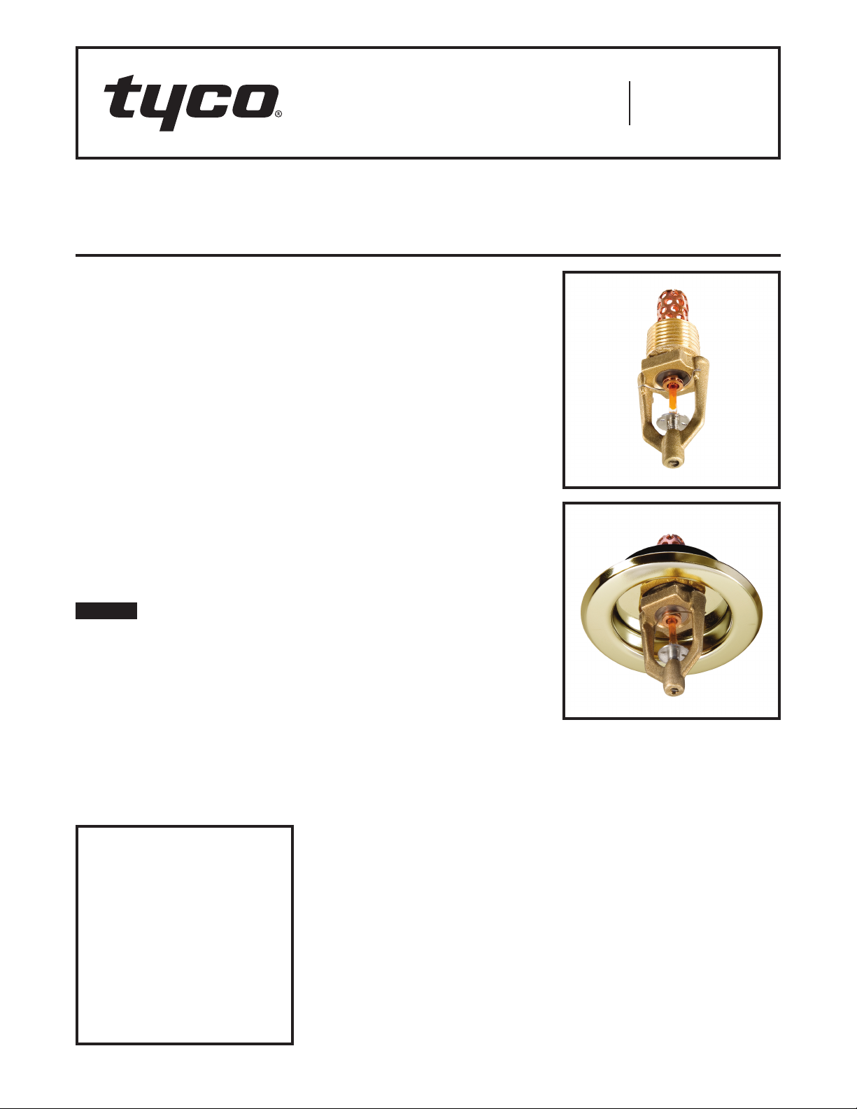
The TYCO Ultra Low Flow AQUAMIST
Nozzles Type ULF AM27 are closed
(automatic) nozzles intended for use
with engineered, water-mist systems.
They are low-pressure nozzles that
utilize a single fluid jet impinging on a
diffuser to produce a spray having a
range of water droplet sizes suitable
for the control of Class A fires.
It is recommended that the end user be
consulted with respect to the suitability of the materials of construction and
finish for any given corrosive environment. The effects of ambient temperature, concentration of chemicals, and
gas/chemical velocity should be considered, at a minimum, along with the
corrosive nature to which the nozzles
may be exposed.
NOTICE
The Type ULF AM27 AQUAMIST
Nozzles de scribed herein must be
installed and maintained in compliance
with this document and with the applicable standards of the NATIONAL FIRE
PROTECTION ASSOCIATION (NFPA),
in addition to the standards of any
authorities having jurisdiction. Failure
to do so may impair the performance
of these devices.
The design of individual water mist
systems can vary considerably,
depending on the characteristics and
nature of the hazard and the basic
IMPORTANT
Refer to Technical Data Sheet
TFP2300 for warnings pertaining to
regulatory and health information.
Always refer to Technical Data
Sheet TFP700 for the “INSTALLER
WARNING” that provides cautions
with respect to handling and installation of sprinkler systems and components. Improper handling and
installation can permanently damage
a sprinkler system or its components and cause the sprinkler to fail
to operate in a fire situation or cause
it to operate prematurely.
purpose of the water mist system.
Because of these variations, the design
of water mist systems for fire protection must only be performed by experienced designers who thoroughly
understand the limitations as well as
capabilities of such systems.
The owner is responsible for maintaining their fire protection system
and devices in proper operating condition. Contact the installing contractor or product manufacturer with any
questions.
Approvals
The TYCO Type ULF AM27 AQUAMIST Nozzles in a 57°C (135°F) temperature rating and in a natural brass
finish are Factory Mutual Approved
when used as part of an engineered,
wet pipe water mist system. In particular, the FM Approval testing was performed in accordance with FM Class
5560, Approval Standard for Water Mist
Systems.
Technical
Data
Discharge Coefficient
K = 11,7 LPM/bar½
(K = 0.81 GPM/psi½)
Thread Connection
1/2 inch NPT
Finish
Natural Brass
Chrome Plated
White Coated
Temperature Ratings
Refer to Table A
Physical Characteristics
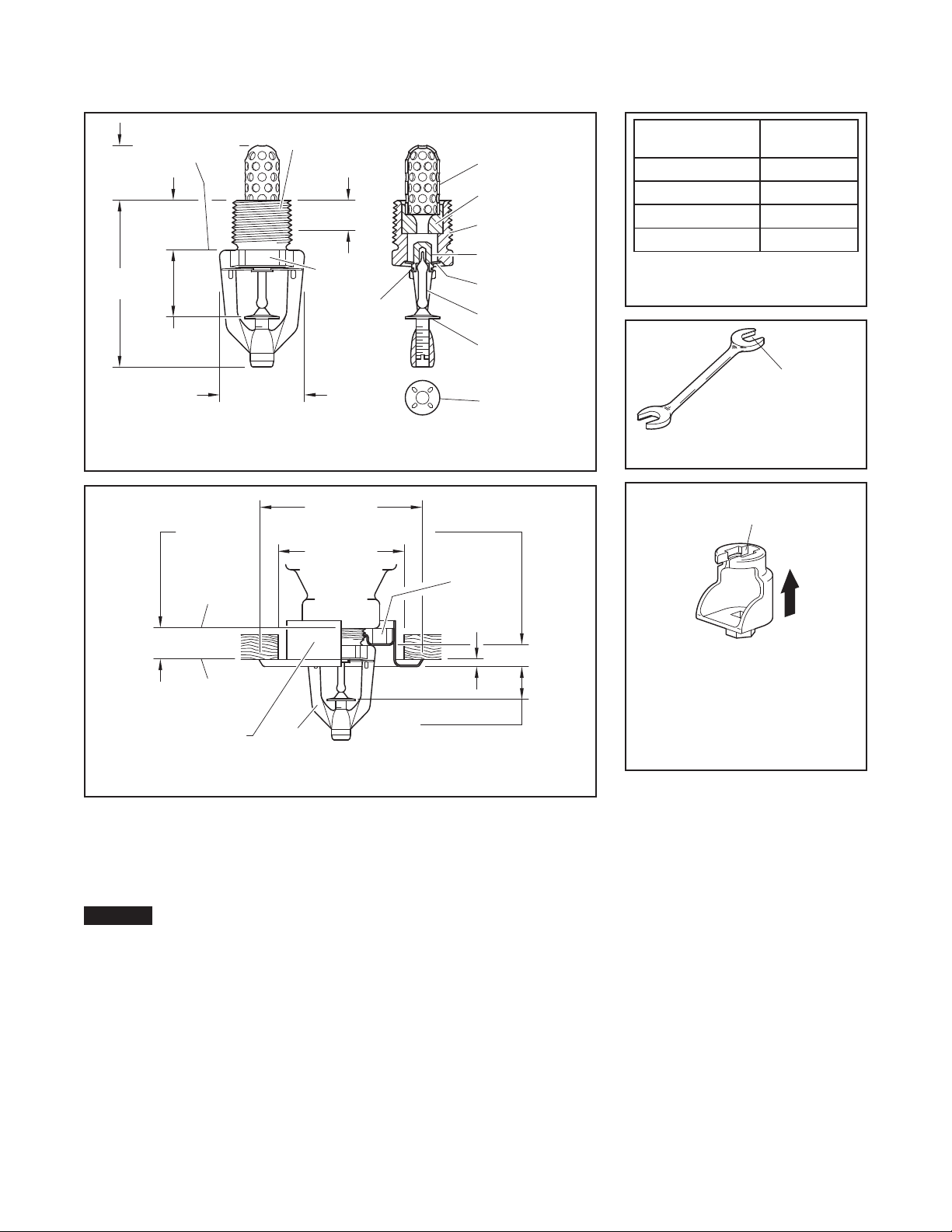
Frame . . . . . . . . . . . . . . . . . . . . . . . . . . . . .Brass
Strainer . . . . . . . . . . . . . . . . . . . . . . . . . . Copper
Orifice Insert . . . . . . . . . . . . . . . . . . . . . . .Bronze
Button . . . . . . . . . . . . . . . . . . . . . . . . . . . .Bronze
Sealing Assembly ..Beryllium Nickel w/TEFLON
Ejection Spring . . . . . . . . . . . . . . Stainless Steel
Bulb . . . . . . . . . . . . . . . . . . . . . . . . . . . . . . .Glass
Diffuser/Loading Screw . . . . . . . Stainless Steel
The smallest waterway (orifice) diameter of the Orifice Insert is nominally 4,3
mm (0.169 inches). The diameter of the
Inlet Strainer perforations is nominally
3,2 mm (0.125 inches).
Design
Criteria
Obtain guidance for the design of a
water-mist system that utilizes the
TYCO Type ULF AM27 AQUAMIST
Nozzles from the Technical Services
department.
Page 1 of 4 AUGUST 2018 TFP2227
Page 2
TFP2227
Assembly
Components:
SHAPE
ESCUTCHEON
20,6 mm
61,9 mm
(2-7/16")
11,1 mm
1/2"
AM27
73,0 mm
CLOSURE
WRENCH RECESS
WRENCH
WRENCHING AREA
Page 2 of 4
(13/16")
PLATE SEATING
SURFACE
17,5 mm
(11/16")
25,4 mm
(1")
TYPE ULF AM27 AQUAMIST NOZZLE
11,1±3,2 mm
(7/16±1/8")
FACE OF
NOZZLE
FITTING
(7/16")
NPT
NOMINAL
MAKE-IN
WRENCH
FLATS
8
31,0 mm
(1.22")
FIGURE 1
NOMINAL DIMENSIONS
(2-7/8") DIA.
57,2 mm
(2-1/4") DIA.
1
2
3
4
5
6
7
DIFFUSER
12,7 mm (1/2")
6,4 mm (1/4")
MOUNTING
PLATE
3,2 mm
(1/8")
1
2
3
4
5
6
7
8
-
Strainer
-
Orice
Insert
-
Frame
-
Button
-
Sealing
-
Bulb
-
Diffuser/
Loading
Screw
-
Ejection
Spring
Temperature
Rating
57° C/13 5°F Orange
68°C/155° F Red
79 °C/175° F Yel low
93°C/200°F Green
Bulb Fluid
Color
TABL E A
TE M PE R ATU R E R ATIN GS
SELECTION
(USE ONLY
END "A")
FIGURE 3
W-TYPE 6 WRENCH
RECESS
MOUNTING
SURFACE
TYPE ULF AM27 AQUAMIST NOZZLE
WITH STYLE 20 RECESSED ESCUTCHEON
Installation
The TYCO Type ULF AM27 AQUAMIST
Nozzles must be installed in accordance with this section.
NOTICE
Do not install any bulb-type nozzle if
the bulb is cracked or there is a loss
of liquid from the bulb. With the nozzle
held horizontally, a small air bubble
should be present. The diameter of
the air bubble is approximately 1,6 mm
(1/16 inch) for the 57°C (135°F) to 2,4
mm (3/32 inch) for the 93°C (200°F)
temperature ratings.
Obtain a leak-tight 1/2 inch NPT nozzle
joint by applying a minimum-to-maximum torque of 9,5 to 19,0 Nm (7 to
14 ft.-lbs.). Higher levels of torque
can distort the nozzle inlet and cause
leakage or impairment of the nozzle.
FIGURE 2
Do not attempt to compensate for
insufficient adjustment in the escutcheon plate by under or over-tightening
the nozzle. Re-adjust the position of the
nozzle fitting to suit.
Type ULF AM27
The Type ULF AM27 AQUAMIST
Nozzles must be installed in accordance with the following instructions.
Step 1. Install the Type ULF AM27
in the pendent position as shown in
Figure 1.
Step 2. With pipe-thread sealant
applied to the pipe threads, handtighten the nozzle into the nozzle fitting.
Step 3. Tighten the nozzle into the
nozzle fitting using only the W-Type 6
Wrench (Ref. Figure 3). With reference
to Figure 1, apply the W-Type 6 Wrench
to the Wrench Flats.
17,4 mm (11/16")
11,1 mm (7/16")
PUSH WRENCH
IN TO ENSURE
ENGAGEMENT
WITH SPRINKLER
FIGURE 4
W-TYPE 7
RECESSED WRENCH
Type ULF AM27 Recessed
The Type ULF AM27 AQUAMIST
Recessed Nozzles must be installed
in accordance with the following
instructions.
Step 1. Install the Recessed Type ULF
AM27 in the pendent position as shown
in Figure 2.
Step 2. After installing the Style 20
Mounting Plate, as applicable, over
the nozzle threads and with pipe-thread
sealant applied to the pipe threads,
hand-tighten the nozzle into the nozzle
fitting.
Step 3. Tighten the nozzle into the
nozzle fitting using only the W-Type 7
Recessed Wrench (Ref. Figure 4). With
reference to Figure 1, apply the W-Type
7 Recessed Wrench to the nozzle
Wrench Flats.
Step 4. After the ceiling has been
in stalled or the finish coat has been
Page 3

TFP2227
Page 3 of 4
applied, slide on the Style 20 Closure
over the Type ULF AM27 Nozzle and
push the Closure over the Mounting
Plate until its flange comes in contact
with the ceiling.
Care and
Maintenance
The TYCO Type ULF AM27 AQUAMIST
Nozzles must be maintained and serviced in accordance with this section.
Before closing a fire protection system
main control valve for maintenance
work on the fire protection system
that it controls, obtain permission to
shut down the affected fire protection
system from the proper authorities
and notify all personnel who may be
affected by this action.
Absence of an escutcheon, which is
used to cover a clearance hole, can
delay the time to nozzle operation in a
fire situation.
Absence of an escutcheon, which is
used to cover a clearance hole, can
delay the time to nozzle operation in a
fire situation.
The owner must assure that the sprinklers are not used for hanging any
objects and that the sprinklers are only
cleaned by means of gently dusting
with a feather duster; otherwise, nonoperation in the event of a fire or inadvertent operation may result.
Sprinklers which are found to be
leaking or exhibiting visible signs of
corrosion must be replaced.
Automatic sprinklers must never be
painted, plated, coated, or otherwise altered after leaving the factory.
Modified sprinklers must be replaced.
Sprinklers that have been exposed to
corrosive products of combustion, but
have not operated, should be replaced
if they cannot be completely cleaned
by wiping the sprinkler with a cloth or
by brushing it with a soft bristle brush.
Care must be exercised to avoid
damage to the sprinklers - before,
during, and after installation. Sprinklers damaged by dropping, striking,
wrench twist/slippage, or the like, must
be replaced. Also, replace any sprinkler that has a cracked bulb or that has
lost liquid from its bulb. (Ref. Installation Section.)
The owner is responsible for the
inspection, testing, and maintenance of
their fire protection system and devices
in compliance with this document, as
well as with the applicable standards
of the NATIONAL FIRE PROTECTION
ASSOCIATION - for example, NFPA 20,
25, and 750 - in addition to the standards of any other authorities having
jurisdiction. Contact the installing contractor or product manufacturer with
any questions.
Water-mist fixed systems should be
inspected, tested, and maintained by
a qualified Inspection Service in accordance with local requirements and/or
national codes.
Limited
Warranty
For warranty terms and conditions, visit
www.tyco-fire.com.
Ordering
Procedure
Contact your local distributor for availability. When placing an order, indicate
the full product name and Part Number
(P/N).
Type ULF AM27
AQUAMIST Nozzles
Specify: Type ULF AM27 AQUAMIST
Nozzle with (type of) finish and (specify)
tem perature rating, P/N (specify):
Natural Brass
57° C (135°F ) ..................49 -212-1-135
68°C (15 5°F ) ..................49 -212-1-155
79°C (175°F ) ..................49 -212-1-175
93°C (200°F) ..................49-212-1-200
Chrome Plated
57° C (135°F ) ..................49-212-9-135
68°C (15 5°F ) ..................49-212-9-155
79°C (175°F ) ..................49-212-9-175
93°C (200°F) ..................49 -212-9-200
Signal White* (RAL 9003)
57° C (135°F ) ..................49-212- 4-135
68°C (15 5°F ) ..................49 -212-4-15 5
79°C (175°F ) ..................49-212-4-175
93°C (200°F) ..................49 -212-4-200
Pure White** ( RAL 9 010)
57° C (135°F ) ..................49-212-3-135
68°C (15 5°F ) ..................49 -212-3-15 5
79°C (175°F ) .................49-212-3-175
93°C (200°F) .................49-212-3-200
* Previou sly known a s Bright Wh ite
** Eastern Hemis phere sales only
Recessed Escutcheon
Specify: Style 20 Recessed Escutcheon with (specify*) finish, P/N (specify*).
* Refer to Technical Data Sheet TFP770.
Nozzle Wrench
Specify: W-Type 6 Wrench,
P/N 56-000-6-387
Specify: W-Type 7 Recessed Wrench,
P/N 56-850-4-001
Page 4

TFP2227
Page 4 of 4
1400 Pennbrook Parkw ay, Lansd ale, PA 194 46 | Teleph one +1-215-362-070 0
© 2018 John son Control s. All right s reserved. A ll specifica tions and ot her informa tion shown wer e current as o f document rev ision date an d are subject t o change wit hout notice.
NATIONAL FIRE P ROTECTION ASSOCIATIO N and NFPA are register ed trademarks of N ational Fire Protec tion Associati on;
TEFLON is a regi stered tradema rk of DuPont
 Loading...