

Page 1
Technical Services
800-381-9312 | +1-401-781-8220
www.tyco-fire.com
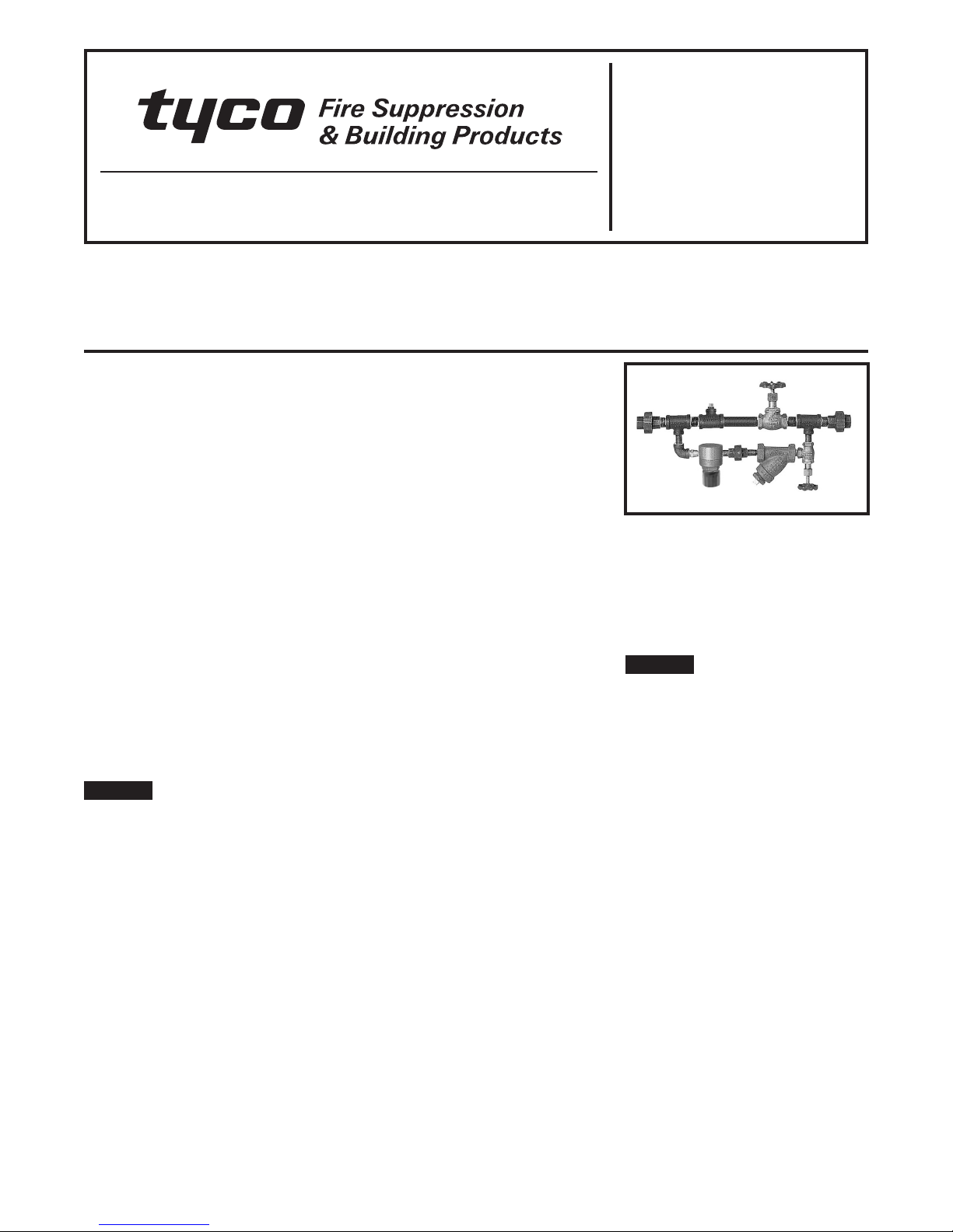
Model AMD-1 Automatic Air Maintenance Device
Pressure Reducing Type with
Field-Adjustable Pressure Regulator
General
Description
The TYCO Model AMD-1 Automatic Air
Maintenance Device is an automatic,
eld-adjustable, pressure reducing
device. It is used to control the pressure in a dry pipe sprinkler system, preaction system, or dry pilot line system
of a dry pilot actuated deluge or preaction valve.
The Model AMD-1 Device is utilized
in applications where there is a compressed air (or nitrogen) source controlled at a higher pressure than the
desired system pressure. Pressure
sources include plant air supplies with
their own automatic compressor controls or nitrogen supplies with single-stage, cylinder-mounted pressure
regulators.
The Model AMD-1 Automatic Air Maintenance Device is a re-designation for
the Central Model D-2, Gem Model
F324, and Star Model S460.
NOTICE
The Model AMD-1 Automatic Air Maintenance Devices described herein
must be installed and maintained in
compliance with this document and
with the applicable standards of the
National Fire Protection Association,
in addition to the standards of any
authorities having jurisdiction. Failure
to do so may impair the performance
of these devices.
Owners are responsible for maintaining their fire protection system and
devices in proper operating condition.
The installing contractor or sprinkler
manufacturer should be contacted
with any questions.
Technical
Data
Approvals
UL and C-UL Listed
FM Approved
NYC Approved under MEA 206-02-E
Maximum Inlet Air (or Nitrogen)
Supply Pressure
200 psi (13,8 bar)
Field-Adjustable Outlet Pressure
Range
5 to 70 psi (0,4 to 4,8 bar)
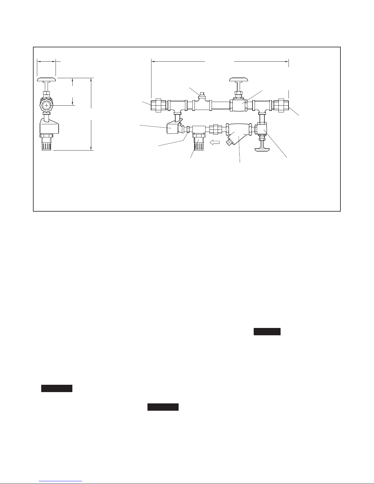
Assembly
Major components illustrated in Figure
1 are factory assembled with galvanized steel nipples and malleable iron
pipe ttings.
Operation
The By-Pass Valve in the Model AMD-1
Automatic Air Maintenance Device is
opened to quickly ll the system during
initial pressurization. Once the re quired
system pressure has been reached,
the By-Pass Valve is closed and the Air
Supply Control Valve is left open to
place the Model AMD-1 Device in automatic operation.
When there is a small leak in the system, the Pressure Regulator automatically maintains system pressure at the
preset level. The 3/32 inch (2,4 mm) orice in the Restrictor Check Valve limits
the ow of air from the Pressure Regulator into the system to a value signicantly less than that exhausted by the
operation of a 5.6 K-factor sprinkler.
Installation
The TYCO Model AMD-1 Automatic Air
Maintenance Device must be installed
in accordance with the following
instructions.
NOTICE
Moisture build-up can adversely affect
performance. Suitable consideration
must be given to the removal of excessive moisture from the compressed air
supply.
1.
Make connections a minimum of
1/2 inch (DN15) pipe size between
the inlet air supply and the Model
AMD-1 Device, as well as between
the Model AMD-1 Device and the
system to pressurize.
2. Place a 1/2 inch (DN15), non-spring
loaded, rubber-faced, swing-type
check valve between the Model
AMD-1 Device and the system to
pressurize. A check valve of this
type is provided in the air supply
trim of TYCO dry pipe valves, preaction valves, and dry pilot trim.
Page 1 of 4 JULY 2010 TFP1221
Page 2
TFP1221
Page 2 of 4
2"
(50,8 mm)
3-1/4"
(82,6 mm)
8-1/2"
(215,9 mm)
1/2" NPT
OUTLET
CONNECTION
(TO SYSTEM)
LABEL
RESTRICTOR
CHECK VALVE
P/N 92-326-1-003
Setting
Procedure
The TYCO Model AMD-1 Automatic
Air Maintenance Device must be set
in accordance with the following
instructions.
1. Determine the pressure that meets
the minimum requirements of the
system to pressurize.
2. Close the Model AMD-1 By-Pass
Valve, and close the Model AMD-1
Air Supply Control Valve.
3. Open the control valve in the air
supply trim of the system to pressurize and then reduce the system
air pressure to 0 psi.
4. Close the control valve in the
air supply trim of the system to
pressurize.
5. Remove the system pressure gauge
from its connection and temporarily
install it in the 1/4 inch NPT Model
AMD-1 Gauge Test Port.
CAUTIO N
Before removing the plug, make
certain that the piping to which the
Model AMD-1 Gauge Test Port is
connected is at 0 psi. Failure to do
so may result in personal injury or
property damage.
6. Open the Air Supply Control Valve in
the Model AMD-1 Device.
16-1/8""
(409,6 mm)
1/4" NPT
GAUGE
TEST PORT
PRESSURE
REGULATOR
(ADJUSTABLE)
P/N 92-324-1-012
STRAINER
P/N 52-353-1-002
FIGURE 1
MODEL AMD-1
AUTOMATIC AIR MAINTENANCE DEVICE
7. While observing the relocated pressure gauge, adjust the output pressure of the Pressure Regulator. Pull
the knob out and away from the
Pressure Regulator body and then
slowly turn the knob clockwise, as
viewed from the knob end of the
Pressure Regulator, to increase
pressure, and counter-clockwise to
decrease pressure.
When decreasing pressure, the air
pressure must be relieved downstream of the Pressure Regulator
by temporarily opening the control
valve in the air supply trim of the
system to pressurize, assuming that
the system to pressurize is at 0 psi.
After the Pressure Regulator is set,
push the knob in and towards the
Pressure Regulator body to “snap”
it in a locked position.
8. Close the Air Supply Control Valve
in the Model AMD-1 Device.
9. Return the system air pressure
gauge to its normal location. Reinstall the 1/4 inch pipe plug in the
Model AMD-1 Gauge Test Port.
Apply pipe-thread sealant sparingly
to the plug threads only.
CAUTIO N
Before removing the pressure
gauge, make certain that the piping
to which the Model AMD-1 Gauge
Test Port is connected is at 0 psi.
Failure to do so may result in personal injury or property damage.
BY-PASS VALVE
(NORMALLY
CLOSED)
P/N 46-047-1-004
1/2" NPT
INLET CONNECTION
(FROM COMPRESSED
AIR SUPPLY)
AIR SUPPLY
CONTROL VALVE
(NORMALLY OPEN)
P/N 46-048-1-002
10. Open the control valve in the
air supply trim to the system to
pressurize.
11. Open the Air Supply Control Valve
in the Model AMD-1 Device.
12. Open the By-Pass Valve in the
Model AMD-1 Device.
13. Close the By-Pass Valve after the
system is pressurized to approximately 5 psi (0,4 bar) less than the
minimum required system pres sure
determined in Step 1.
14. After the system pressure stabilizes, note the value and compare
with the requirement. Re-adjust the
Pressure Regulator, as required.
NOTICE
If the system was over-pressurized during manual fill, open a
suitable connection to the system
and manually reduce the pressure
to the desired value. The Model
AMD-1 Automatic Air Maintenance
Device then automatically maintains
the preset system pressure. The
Restrictor Check Valve prevents
the Pressure Regulator from bleeding down the system pressure.
In order to minimize the time for
system trip in the event of a sprinkler operation, set the system pressure at the minimum required value.
Page 3

TFP1221
Page 3 of 4
Care and
Maintenance
The TYCO Model AMD-1 Automatic
Air Maintenance Device must be maintained and serviced in accordance with
the following instructions, in addition to
any specic requirements of the NFPA.
Any impairment must be immediately
corrected.
NOTICE
Before closing a fire protection system
main control valve for maintenance
work on the fire protection system
that it controls, obtain permission to
shut down the affected fire protection system from the proper authorities and notify all personnel who may
be affected by this action.
It is recommended that accumulated
moisture be removed from air supply
moisture ltration equipment at least
quarterly. More frequent inspections
may be necessary in particularly humid
environments.
After placing a re protection system
in service, notify the proper authorities
and advise those responsible for monitoring proprietary and/or central station alarms.
Responsibility lies with owners for the
inspection, testing, and maintenance of
their re protection system and devices
in compliance with this document, as
well as with the applicable standards of
the National Fire Protection Association
(for example, NFPA 25), in addition to
the standards of any other authorities
having jurisdiction. Contact the installing contractor or sprinkler manufacturer regarding any questions.
Automatic sprinkler systems are recommend to be inspected, tested, and
maintained by a qualied Inspection Service in accordance with local
requirements and/or national code.
The Model AMD-1 Device must be
inspected quarterly in accordance with
the following instructions.
1.
Verify that the By-Pass Valve is
closed.
2. Close the Model AMD-1 Air Supply
Control Valve and clean out the 1/4
inch Strainer located at the inlet to
the Restrictor Check Valve. Be sure
to reinstall the strainer screen and
tighten the cap securely.
3.
Open the Model AMD-1 Air Supply Valve and verify that the control valve in the air supply trim to the
system to pressurize is open.
4.
Verify that the system pressure is
essentially the same as the previously established requirement. If
not, adjust the system pressure as
follows:
a.
Close the system’s main control valve and open the main
drain valve. If the system is so
equipped, close the Accelerator
Control Valve.
b.
Follow Steps 1 through 14 in the
Setting Procedure section.
c.
Slowly open the Accelerator Control Valve, as applicable.
d.
Slowly open the main control
valve. After water begins to ow,
slowly close the main drain valve,
then completely open the main
control valve. The Model AMD-1
Automatic Air Maintenance
Device is now ready for service.
Limited
Warranty
Products manufactured by Tyco Fire
Suppression & Building Products
(TFSBP) are warranted solely to the
original Buyer for ten (10) years against
defects in material and workmanship
when paid for and properly installed
and maintained under normal use and
service. This warranty will expire ten
(10) years from date of shipment by
TFSBP. No warranty is given for products or components manufactured by
companies not afliated by ownership
with TFSBP or for products and components which have been subject to
misuse, improper installation, corrosion, or which have not been installed,
maintained, modied or repaired in
accordance with applicable Standards
of the National Fire Protection Association, and/or the standards of any other
Authorities Having Jurisdiction. Materials found by TFSBP to be defective
shall be either repaired or replaced, at
TFSBP’s sole option. TFSBP neither
assumes, nor authorizes any person
to assume for it, any other obligation
in connection with the sale of products or parts of products. TFSBP shall
not be responsible for sprinkler system
design errors or inaccurate or incomplete information supplied by Buyer or
Buyer’s representatives.
In no event shall TFSBP be liable, in
contract, tort, strict liability or under
any other legal theory, for incidental,
indirect, special or consequential damages, including but not limited to labor
charges, regardless of whether TFSBP
was informed about the possibility of
such damages, and in no event shall
TFSBP’s liability exceed an amount
equal to the sales price.
The foregoing warranty is made in lieu
of any and all other warranties, express
or implied, including warranties of merchantability and tness for a particular
purpose.
This limited warranty sets forth the
exclusive remedy for claims based on
failure of or defect in products, materials or components, whether the claim is
made in contract, tort, strict liability or
any other legal theory.
This warranty will apply to the full
extent permitted by law. The invalidity,
in whole or part, of any portion of this
warranty will not affect the remainder.
Ordering
Procedure
Contact your local distributor for availability. When placing an order, indicate the full product name, including
description and Part Number (P/N).
Model AMD-1 Device
Specify: Model AMD-1 Automatic Air
Maintenance Device,
P/N 52-324-2-002.
Replacement Parts
Specify: (description) for use with the
Model AMD-1 Automatic Air Maintenance Device, P/N (from Figure 1).
Page 4

TFP1221
Page 4 of 4
Copyright © 2007 - 2010 Tyco Fire Suppression & Building Products. All rights reserved.
 Loading...