

Page 1
T"-HEAD* Crimping Tools
59170, 59250, 59275, 59300,
69692-1, and 69693-1
PROPER USE GUIDELINES
CumulativeTrauma Disorderscan resultfrom theprolonged useof manually poweredhand tools.Hand toolsare intendedfor occasionaluseand lowvolume
applications. A wide selection of powered application equipment for extended-use, production operations is available.
S
PIDG insulation restricting terminals with
TEFLONt coating, used on stranded copper
wire sizes 26 through 14.
S
PIDG Radiation Resistant Terminals and
Splices on stranded copper wire sizes 26
through 14.
S
PLASTI–GRIP* Terminals on solid or stranded
copper wire sizes 22 through 14.
S
PLASTI–GRIP Butt Splices on solid or
stranded copper wire sizes 26 through 22.
S
Spare Wire Caps on solid or stranded copper
wire sizes 22 through 14.
NOTE
i
Dimensions on this sheet are in millimeters [with
inch equivalent dimensions in brackets]. Figures
and illustrations are for identification only and are
not drawn to scale.
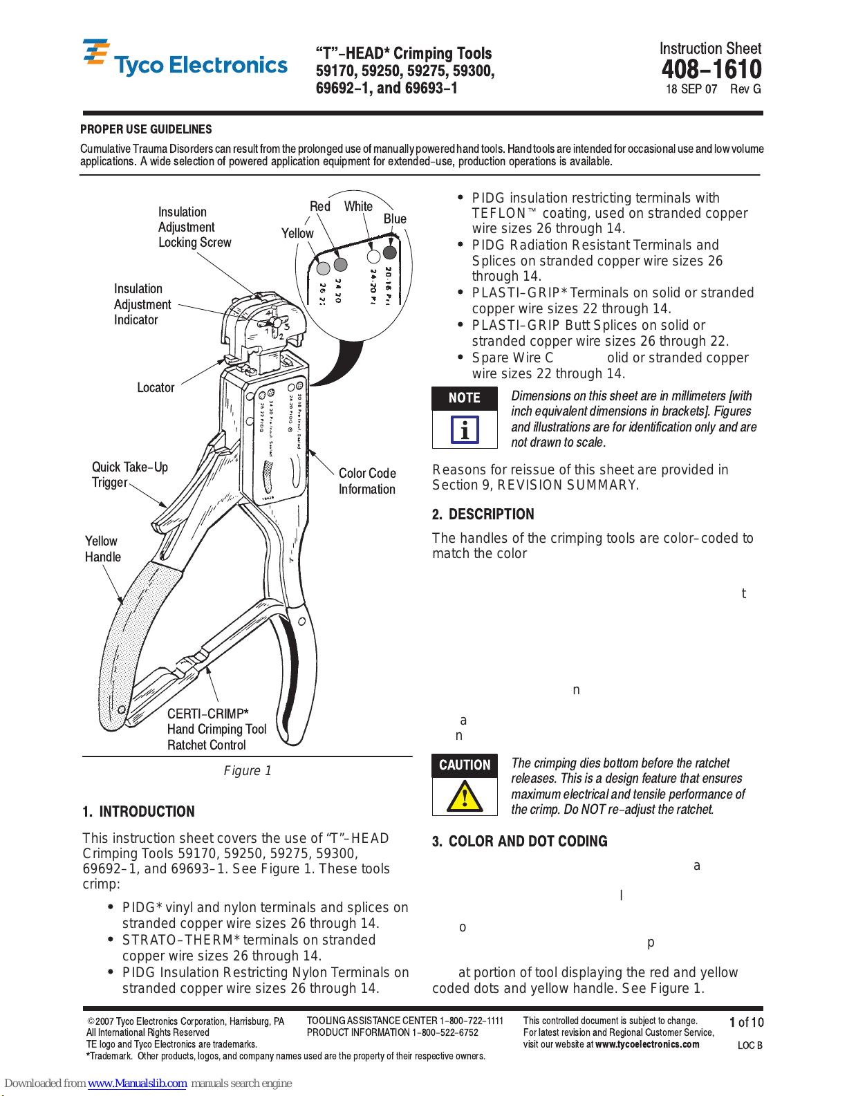
Insulation
Adjustment
Locking Screw
Insulation
Adjustment
Indicator
Locator
Yellow
Red
White
Blue
Instruction Sheet
408-1610
18 SEP 07 Rev G
Quick Take-Up
Trigger
Yellow
Handle
CERTI-CRIMP*
Hand Crimping Tool
Ratchet Control
Figure 1
Color Code
Information
1. INTRODUCTION
This instruction sheet covers the use of “T”–HEAD
Crimping Tools 59170, 59250, 59275, 59300,
69692–1, and 69693–1. See Figure 1. These tools
crimp:
S
PIDG* vinyl and nylon terminals and splices on
stranded copper wire sizes 26 through 14.
S
STRATO–THERM* terminals on stranded
copper wire sizes 26 through 14.
S
PIDG Insulation Restricting Nylon Terminals on
stranded copper wire sizes 26 through 14.
Reasons for reissue of this sheet are provided in
Section 9, REVISION SUMMARY.
2. DESCRIPTION
The handles of the crimping tools are color–coded to
match the color coding of the product to be applied.
The insulation adjustment indicator is used to control
crimp height of the insulation barrel. It can be set at
any of four positions corresponding to insulation
diameter.
Tools also feature a locator, quick take–up trigger, and
color code information.
The CERTI–CRIMP hand crimping tool ratchet control
ensures full crimping of the product. Once engaged,
the ratchet will not release until the handles have
been FULLY closed.
CAUTION
!
The crimping dies bottom before the ratchet
releases. This is a design feature that ensures
maximum electrical and tensile performance of
the crimp. Do NOT re-adjust the ratchet.
3. COLOR AND DOT CODING
Note that tool handles and terminal, splice and cap
insulation are color coded for a given wire range as
listed in Figure 2. Crimp the color coded terminal,
splice or cap in the matching color coded portion of
the tool. For example, when using Hand Tool 59275,
yellow coded PIDG terminals and splices and red
coded pre–insulated seated splices must be crimped
in that portion of tool displaying the red and yellow
coded dots and yellow handle. See Figure 1.
E
2007 TycoElectronicsCorporation,Harrisburg,PA
All International Rights Reserved
TE logo and Tyco Electronics aretrademarks.
*Trademark. Other products, logos, and company names used are the property of their respective owners.
TOOLING ASSISTANCE CENTER 1-800-722-1111
PRODUCT INFORMATION1-800-522-6752
This controlled document is subject to change.
For latest revision and Regional Customer Service,
visit our website at
www.tycoelectronics.com
1
of 10
LOC B
Page 2
T"-HEAD Crimping Tools
408-1610
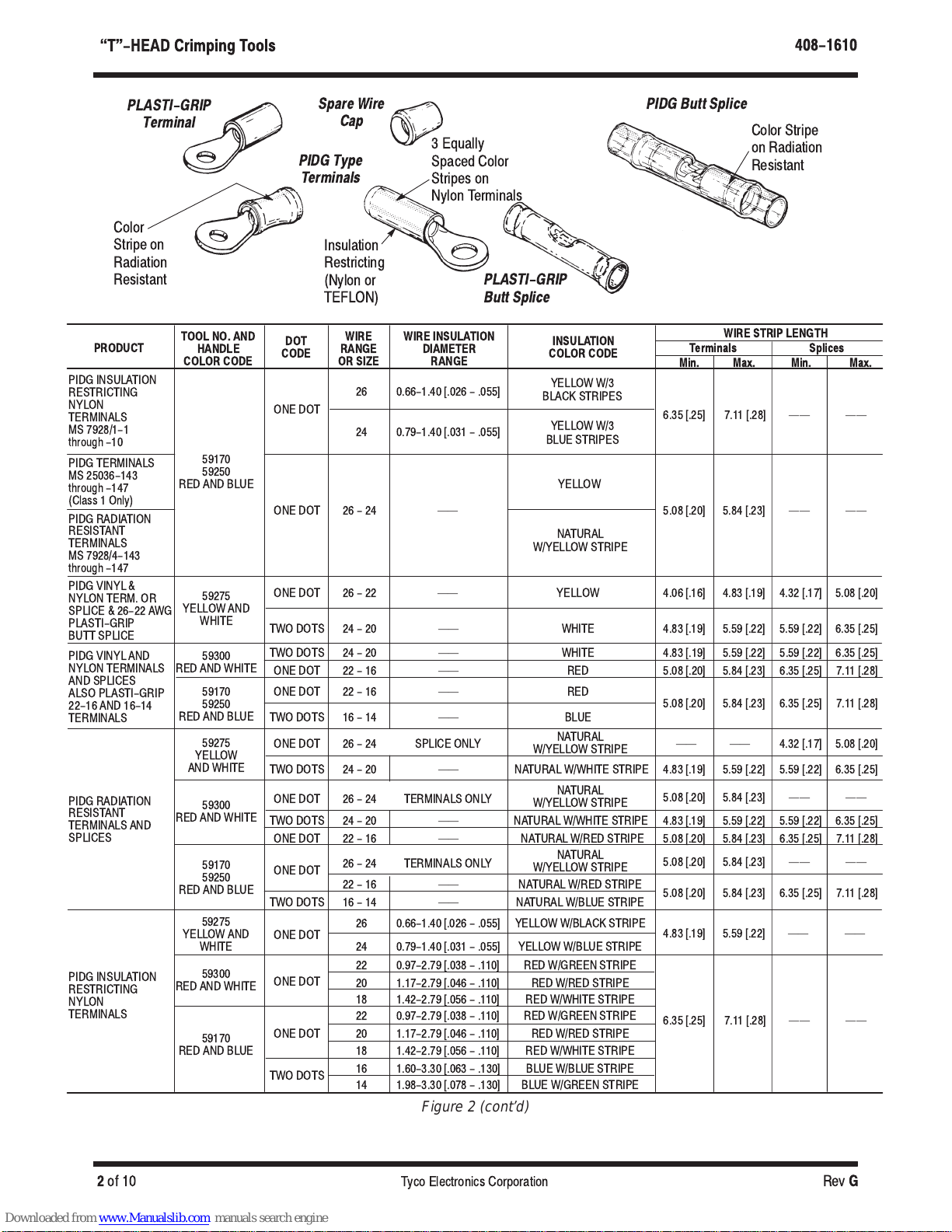
PLASTI-GRIP
Terminal
Color
Stripe on
Radiation
Resistant
PRODUCT
PIDG INSULATION
RESTRICTING
NYLON
TERMINALS
MS 7928/1-1
through -10
PIDG TERMINALS
MS 25036-143
through -147
(Class 1 Only)
PIDG RADIATION
RESISTANT
TERMINALS
MS 7928/4-143
through -147
PIDG VINYL &
NYLON TERM. OR
SPLICE & 26-22 AWG
PLASTI-GRIP
BUTT SPLICE
PIDG VINYL AND
NYLON TERMINALS
AND SPLICES
ALSO PLASTI-GRIP
22-16 AND 16-14
TERMINALS
PIDG RADIATION
RESISTANT
TERMINALS AND
SPLICES
PIDG INSULATION
RESTRICTING
NYLON
TERMINALS
TOOL NO. AND
HANDLE
COLOR CODE
59170
59250
RED AND BLUE
59275
YELLOW AND
WHITE
59300
RED AND WHITE
59170
59250
RED AND BLUE
59275
YELLOW
AND WHITE
59300
RED AND WHITE
59170
59250
RED AND BLUE
59275
YELLOW AND
WHITE
59300
RED AND WHITE
59170
RED AND BLUE
Spare Wire
Cap
PIDG Type
Terminals
3 Equally
Spaced Color
Stripes on
PIDG Butt Splice
Color Stripe
on Radiation
Resistant
Nylon Terminals
Insulation
Restricting
ĊĊ
ĊĊ
PLASTI-GRIP
Butt Splice
INSULATION
COLOR CODE
YELLOW W/3
BLACK STRIPES
YELLOW W/3
BLUE STRIPES
YELLOW
NATURAL
W/YELLOW STRIPE
YELLOW
WHITE
NATURAL
W/YELLOW STRIPE
NATURALW/WHITE STRIPE
NATURAL
W/YELLOW STRIPE
NATURAL
W/YELLOW STRIPE
YELLOW W/BLACK STRIPE
YELLOW W/BLUE STRIPE
WIRE STRIP LENGTH
Terminals Splices
Min. Max. Min. Max.
6.35 [.25] 7.11[.28] ĊĊ ĊĊ
5.08 [.20] 5.84 [.23] ĊĊ ĊĊ
4.06 [.16] 4.83 [.19] 4.32 [.17] 5.08 [.20]
4.83 [.19] 5.59 [.22] 5.59 [.22] 6.35[.25]
5.08 [.20] 5.84 [.23] 6.35 [.25] 7.11[.28]
ĊĊ ĊĊ 4.32 [.17] 5.08 [.20]
4.83 [.19] 5.59 [.22] 5.59 [.22] 6.35[.25]
5.08 [.20] 5.84 [.23] ĊĊ ĊĊ
5.08 [.20] 5.84 [.23] ĊĊ ĊĊ
5.08 [.20] 5.84 [.23] 6.35 [.25] 7.11[.28]
4.83 [.19] 5.59 [.22] ĊĊ ĊĊ
6.35 [.25] 7.11[.28] ĊĊ ĊĊ
(Nylon or
TEFLON)
DOT
CODE
ONE DOT
ONE DOT 26 - 24 ĊĊ
ONE DOT
TWO DOTS
TWO DOTS 24 - 20 ĊĊ WHITE 4.83 [.19] 5.59 [.22] 5.59 [.22] 6.35[.25]
ONE DOT 22 - 16 ĊĊ RED 5.08 [.20] 5.84 [.23] 6.35 [.25] 7.11[.28]
ONE DOT 22 - 16 ĊĊ RED
TWO DOTS 16 - 14 ĊĊ BLUE
ONE DOT 26 - 24 SPLICE ONLY
TWO DOTS 24 - 20 ĊĊ
ONE DOT 26 - 24 TERMINALS ONLY
TWO DOTS 24 - 20 ĊĊ NATURALW/WHITE STRIPE 4.83 [.19] 5.59 [.22] 5.59 [.22] 6.35[.25]
ONE DOT 22 - 16 ĊĊ NATURAL W/RED STRIPE 5.08 [.20] 5.84 [.23] 6.35 [.25] 7.11 [.28]
ONE DOT
TWO DOTS 16 - 14 ĊĊ NATURALW/BLUE STRIPE
ONE DOT
ONE DOT
ONE DOT
TWO DOTS
WIRE
RANGE
OR SIZE
26
24
26-22
24-20
26 - 24 TERMINALS ONLY
22 - 16 ĊĊ NATURALW/RED STRIPE
26
24
22 0.97-2.79 [.038 - .110] RED W/GREEN STRIPE
20 1.17-2.79 [.046 - .110] REDW/RED STRIPE
18 1.42-2.79 [.056 - .110] RED W/WHITE STRIPE
22 0.97-2.79 [.038 - .110] RED W/GREEN STRIPE
20 1.17-2.79 [.046 - .110] REDW/RED STRIPE
18 1.42-2.79 [.056 - .110] RED W/WHITE STRIPE
16 1.60-3.30 [.063 - .130] BLUE W/BLUESTRIPE
14 1.98-3.30 [.078 - .130] BLUE W/GREEN STRIPE
WIRE INSULATION
DIAMETER
RANGE
0.66-1.40 [.026 - .055]
0.79-1.40 [.031 - .055]
0.66-1.40 [.026 - .055]
0.79-1.40 [.031 - .055]
Figure 2 (cont’d)
of 10
Tyco Electronics Corporation
Rev
G2
Page 3
T"-HEAD Crimping Tools
408-1610
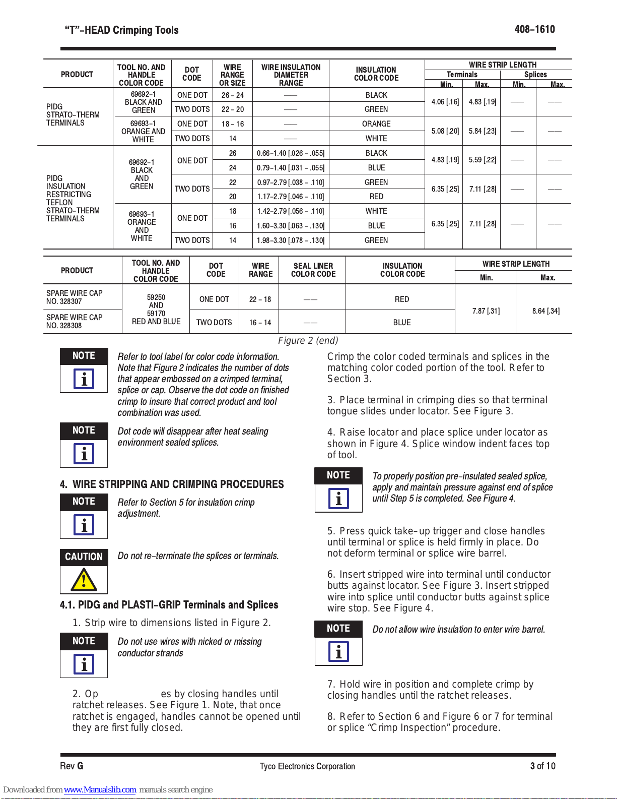
PRODUCT
PIDG
STRATO-THERM
TERMINALS
PIDG
INSULATION
RESTRICTING
TEFLON
STRATO-THERM
TERMINALS
PRODUCT
SPAREWIRE CAP
NO. 328307
SPAREWIRE CAP
NO. 328308
NOTE
i
TOOL NO. AND
HANDLE
COLOR CODE
69692-1
BLACK AND
GREEN
69693-1
ORANGE AND
WHITE
69692-1
BLACK
AND
GREEN
69693-1
ORANGE
AND
WHITE
TOOL NO. AND
HANDLE
COLOR CODE
59250
AND
59170
RED AND BLUE
DOT
CODE
ONE DOT 26 - 24 BLACKĊĊ
TWO DOTS 22 - 20 GREENĊĊ
ONE DOT 18 - 16 ORANGEĊĊ
TWO DOTS 14 WHITEĊĊ
ONE DOT
ONE DOT
TWO DOTS 14 GREEN1.98-3.30 [.078 - .130]
WIRE
RANGE
OR SIZE
26 BLACK0.66-1.40 [.026 - .055]
24 BLUE0.79-1.40 [.031 - .055]
22 GREEN0.97-2.79[.038 - .110]
20 RED1.17-2.79 [.046 - .110]
18 WHITE1.42-2.79 [.056- .110]
16 BLUE1.60-3.30 [.063 - .130]
DOT
CODE
ONE DOT 22 - 18 ĊĊ RED
TWO DOTS 16 - 14 ĊĊ BLUE
WIRE INSULATION
DIAMETER
RANGE
WIRE
RANGE
Figure 2 (end)
Refer to tool label for color code information.
Note that Figure 2 indicates the number of dots
that appear embossed on acrimped terminal,
splice or cap. Observe the dot codeon finished
crimp to insure that correct product andtool
combination was used.
SEAL LINER
COLOR CODE
Crimp the color coded terminals and splices in the
matching color coded portion of the tool. Refer to
Section 3.
3. Place terminal in crimping dies so that terminal
tongue slides under locator. See Figure 3.
INSULATION
COLOR CODE
INSULATION
COLOR CODE
WIRE STRIP LENGTH
Terminals Splices
Min. Max. Min. Max.
4.06 [.16] 4.83 [.19] ĊĊ ĊĊ
5.08 [.20] 5.84 [.23] ĊĊ ĊĊ
4.83 [.19] 5.59 [.22] ĊĊ ĊĊ
6.35 [.25] 7.11[.28] ĊĊ ĊĊTWO DOTS
6.35 [.25] 7.11[.28] ĊĊ ĊĊ
WIRE STRIP LENGTH
Min. Max.
7.87 [.31] 8.64 [.34]
NOTE
Dot code will disappear after heat sealing
environment sealed splices.
i
4. WIRE STRIPPING AND CRIMPING PROCEDURES
NOTE
Refer to Section 5 for insulation crimp
adjustment.
i
CAUTION
!
4.1. PIDG and PLASTI-GRIP Terminals and Splices
1. Strip wire to dimensions listed in Figure 2.
NOTE
Do not re-terminate the splices or terminals.
Do not use wires with nicked or missing
conductor strands
i
2. Open crimping dies by closing handles until
ratchet releases. See Figure 1. Note, that once
ratchet is engaged, handles cannot be opened until
they are first fully closed.
4. Raise locator and place splice under locator as
shown in Figure 4. Splice window indent faces top
of tool.
NOTE
To properly position pre-insulated sealed splice,
apply and maintain pressure against end of splice
i
until Step 5 is completed. See Figure 4.
5. Press quick take–up trigger and close handles
until terminal or splice is held firmly in place. Do
not deform terminal or splice wire barrel.
6. Insert stripped wire into terminal until conductor
butts against locator. See Figure 3. Insert stripped
wire into splice until conductor butts against splice
wire stop. See Figure 4.
NOTE
Do not allow wire insulation to enterwire barrel.
i
7. Hold wire in position and complete crimp by
closing handles until the ratchet releases.
8. Refer to Section 6 and Figure 6 or 7 for terminal
or splice “Crimp Inspection” procedure.
G
Tyco Electronics Corporation
3
of 10Rev
Page 4

T"-HEAD Crimping Tools
408-1610
PIDG and PLASTI-GRIP Terminals
C" B" C" B"
C" B"
Terminal Barrel
Rests Against
Locator
Conductor Butts
Against Locator
Terminal Tongue
Slides Under
Locator
Environmental
Sealed Splice
C" B"
B" Equals Wire Barrel
C" Equals Insulation Barrel
First
Crimp
Window Indent
Faces Top of
Tool
Window
Indent
Wire Stop
PIDG
Terminal
PLASTI-GRIP
Terminal
B" Equals Wire Barrel
C" Equals Insulation Barrel
Figure 3
BUTT Splices
PIDG
PLASTI-GRIP
C" B"
PIDG Insulation
C" B"
Restricting
Window
Indent
Wire Stop
Window
Indent
Wire Stop
4.2. Spare Wire Caps
1. Strip wire to dimensions listed in Figure 2. Crimp
the color coded portion of the tool. Refer to
Section 3.
NOTE
Do not use wire with nicked ormissing conductor
strands.
i
2. Place tool insulation adjustment indicator in
Position 4.
3. Close tool handles until crimping jaws partially
close, but leave enough space for cap to be
inserted between dies.
4. Raise locator so that end of cap rests against
the recessed surface of the locator as shown in
Figure 5.
Spare Wire Caps
Insulation
Adjustment
Indicator at
Position 4
Wire
Barrel
Locator
Raise Locator so
that End of Cap Rests
Against Recessed
Surface of Locator
Figure 5
Conductor Butts
Against Wire Stop
Second
Crimp
Window Indent
Faces Top of Tool
Figure 4
of 10
5. Squeeze quick take–up trigger and close
handles until cap is held firmly in place. Do not
deform cap wire barrel.
6. Insert stripped wire into cap until conductor
bottoms in cap.
7. Hold wire in position and complete crimp by
closing handles until the ratchet releases. Handles
will open automatically and crimped cap may be
removed.
8. Refer to Section 6 and Figure 7 wire cap crimp
inspection procedure.
Tyco Electronics Corporation
Rev
G4
Page 5

T"-HEAD Crimping Tools
408-1610
Accept Reject
A Dot Code (1 or 2 Dots) Must
1
2 6
Appear on All Crimped Items
1
5
2
5
PIDG &
3
8
4
5
PLASTI-GRIP
8
7
4
Terminals
353837
3
PIDG
Butt Splice
Wire
Stop
6
3
4
6
2
1
Wire Barrel Dies Crimped
Splice Insulation
3
8
5
2
1
1
Insulation barrel is in firm contact with wire insulation.
2
Correct color code, dot code, and tool combination.
Wire size is within wire range stamped under terminal
3
tongue or on center of splice.
4
Crimp centered on wire barrel.
End of conductor is flush with, or extends beyond end
5
of terminal wire barrel.
End of conductor against wire stop of splice, or at least
6
flush with, or extended slightly beyond wire barrel.
7
Wire insulation does not enter wire barrel.
8
No nicked or missing conductor strands.
5. INSULATION CRIMP ADJUSTMENT
5.1. PIDG Terminals and Splices
NOTE
PIDG terminals and splices feature a wire
insulation grip".
i
Each tool has four insulation crimp positions. See
Figure 1.
1
2
3
4
5
6
7
8
9
Figure 6
6
Wire insulation extruded. (Insulation crimp too tight on PIDG
terminals and splices) See Section 5.
Wrong dot code and color code combination. See Figure 2.
Wire size is not within wire range stamped on terminal
tongue or splice.
Crimp not centered on wire barrel. (Terminal was not butted
against locator. See Figure 3.)
End of conductor is not flush with or extending beyond end
of wire barrel. (Check for correct strip length.)
Excessive flash or extruded insulation, (wrong tool,
terminal, or splice combination, or damaged dies).
Wire insulation entered wire barrel.
Nicked or missing conductor strands.
Splice was reversed in dies (tool’s locator was not seated in
window indent of splice).
1. Loosen insulation adjustment locking screw (see
top of tool) and turn indicator to Position 4.
2. Place terminal or splice in tool dies.
3. Insert UNSTRIPPED wire into ONLY the
insulation barrel (see Figure 3 or 4) of terminal or
splice.
4. Perform a crimp (Section 4). Remove crimped
terminal or splice and check insulation grip as
follows: Bend the wire back and forth once.
Terminal or splice should retain grip on wire
insulation.
G
Tyco Electronics Corporation
5
of 10Rev
Page 6

T"-HEAD Crimping Tools
408-1610
Accept Reject
A Dot Code (1 or 2 Dots) Must
Appear on All Crimped Items
1
5
2
11
9
4
7
2
1
No flash or extruded insulation.
Correct color code, dot code, and tool combination.
2
Dot coding disappears on sealed splices when they
are heat sealed.
3
Correct wire size used.
4
Wire insulation does not enter wire barrel of splice.
End of conductor against wire stop of splice, or at least
5
flush with, or extended slightly beyond wire barrel.
6
End of conductor bottomed in cap.
7
Full width of crimp is over wire barrel.
8
No nicked or missing conductor strands.
9
Crimp centered on wire barrel.
10
Splice insulation is in contact with wire insulation.
8
1
4 8 6
5
3
Wire Stop
3
PLASTI-GRIP
Butt Splice
Spare Wire Cap
1
2
3
4
5
6
7
8
9
10
11
7
Excessive flash or extended insulation. (Crimped in
smaller dies on wrong side of tool.) Also, check for
damaged dies.
Wrong dot code and color code combination. See Figure 2.
Incorrect wire size used.
Wire insulation entered wire barrel.
End of conductor is not flush with or extending beyond
end of wire barrel. (Check strip length.)
End of conductor not bottomed in cap.
Half of crimp off end of wire barrel (Cap was not bottomed
in recess of locator.)
Nicked or missing conductor strands.
Crimp not centered on wire barrel. (Tool locator not
seated in window indent.)
Splice insulation is not in contact with wire insulation.
1
2
5
9
8
4
5
1
6
8
2
3
3
5. If wire pulls out, set insulation adjustment
indicator to next tighter position — Position 3.
6. Perform a crimp and repeat adjustment as
necessary until desired insulation grip is obtained.
Do not use a tighter setting than required.
7. Tighten insulation adjustment locking screw (see
top of tool).
of 10
Figure 7
5.2. PLASTI-GRIP Terminals and Splices
NOTE
i
1. Set insulation adjustment indicator in Position 4
for wire having a large insulation diameter.
2. Set insulation adjustment indicator in Position 3
for wire having a medium insulation diameter.
Tyco Electronics Corporation
PLASTI-GRIP terminals and splices feature a
wire insulation support" only.
Rev
G6
Page 7

T"-HEAD Crimping Tools
408-1610
3. Set insulation adjustment indicator in Position 2
for wire having a small insulation diameter.
4. Set insulation adjustment indicator in Position 1
for wire having thin wall insulation. Terminal or
splice insulation should ideally be in contact with
wire insulation.
6. CRIMP INSPECTION
Inspect crimped terminals, splices and spare wire
caps by checking the features described in Figure 6
or 7.
Use only the crimped items that meet the conditions
shown in the ACCEPT column.
REJECT terminals, splices, and spare wire caps can
be avoided through careful use of instructions and by
performing regular tool maintenance as instructed in
this document.
NOTE
i
Locators in Crimping Tools69692-1 and
69693-1 are locked in the down position. Refer
to Instruction Sheet 408-7424 forcrimp height
inspection of these tools.
7. MAINTENANCE AND INSPECTION
NOTE
Make certain the degreasing compounddoes not
attack paint or plastic materials.
i
Remove remaining degreasing compound with a lint
free cloth. When degreasing compounds are not
available, tool may be wiped clean with a lint free
cloth. Relubricate tool, as instructed in Paragraph 7.3
before placing it back in service.
7.2. Visual Inspection
1. Visually inspect the tool for missing parts, then
operate the tool and note the return action of the
spring–loaded handles. If parts are missing or
defective, refer to Figure 12 for customer
replaceable parts.
2. Visually inspect the die closure surfaces for
flattened, broken, pitted, or chipped conditions.
Although dies may gage within permissible limits,
worn or damaged die closure surfaces are
objectionable and can affect the quality of the
crimp. Examples of possible damaged die closure
surfaces are shown in Figure 8.
Flattened
Broken Corner
Tyco Electronics recommends that a
maintenance/inspection program be performed
periodically to ensure dependable and uniform
terminations. Tools should be inspected at least once
a month. Frequency of inspection may be adjusted to
suit your requirements through experience.
Frequency of inspection is dependent upon:
1. The care, amount of use, and handling of the
tool.
2. The type and size of the products crimped.
3. The degree of operator skill.
4. The presence of abnormal amounts of dust and
dirt.
5. Your own established standards.
All tools are inspected before packaging. Since there
is a possibility of tool damage in shipment, new tools
should be inspected in accordance with Section 7
when received in your plant. Due to the precision
design,
it is important that no parts of these tools be
interchanged except those replacement parts listed in
Figure 12.
7.1. Cleaning
The tool should be immersed (handles partially
closed) in degreasing compound to remove
accumulated dirt, grease, and foreign matter.
Chipped
Edge
Figure 8
Pitted
7.3. Lubrication
Lubricate all pins, pivot points, and bearing surfaces
with SAE 20 motor oil as follows:
Tools used in daily production—Lubricate daily
Tools used daily (occasional)—Lubricate weekly
Tools used weekly—Lubricate monthly
Wipe excess oil from tool, particularly from crimping
area. Oil transferred from the crimping area onto
certain terminations may affect the electrical
characteristics of an application.
G
Tyco Electronics Corporation
7
of 10Rev
Page 8

T"-HEAD Crimping Tools
408-1610
7.4. Gaging the Crimping Chamber
Each tool is inspected for proper die closures before
packaging. An inspection should be performed
periodically to check the tool die closures for
excessive wear.
NOTE
i
This inspection requires the use of plug gages
conforming to the dimensions listed in Figures 9 and
10. Tyco Electronics does not manufacture or market
these gages.
To gage the crimping area(s), refer to Figure 11 and
proceed as follows:
1. Clean oil or dirt from the crimping chamber and
plug gage.
2. Close handles of tool until wire barrel dies are
bottomed. Do not apply additional pressure to tool
handles.
3. With wire barrel dies bottomed, inspect the wire
barrel crimping chamber using the proper plug
gage. Lift the spring–loaded locator up and hold
gage in straight alignment with the crimping
chamber. Carefully try to insert, without forcing, the
GO element. See Figure 11, Detail A. The GO
element must pass completely through the
crimping area.
4. Try to insert the NO–GO element. The NO–GO
element may enter partially, but must not pass
completely through the crimping area.
5. Set insulation adjustment indicator in Position 1.
Measure both insulation crimping chambers with
the proper GO plug gages in the same manner as
Steps 2 and 3. See Figure 11, Detail B.
The following plug gaging informationfor
insulation crimping chambers is provided for
customers specifically requiringthis information.
If plug gaging is not required, inspectthe die
closures using an alternate procedure,i.e.,
performing the Insulation Crimp Adjustment"
(see Section 5) and VisualInspection" (see
Paragraph 7.2).
crimping areas do not conform to the inspection, the
tool must be repaired. Refer to Section 8,
REPLACEMENT AND REP AIR.
7.5. Ratchet Control Inspection
Obtain a .025–mm [.001–in.] shim that is suitable for
checking the clearance between the bottoming
surfaces of the crimping dies. To inspect the
CERTI–CRIMP hand crimping tool ratchet control:
1. Perform a crimp using the largest wire size for
your tool.
2. While holding the wire in place, squeeze the tool
handles together until the ratchet releases. Hold
the tool in this position, maintaining just enough
pressure to keep the dies closed.
3. Check the clearance between the bottoming
surfaces of the crimping dies. If the clearance is
.025 [.001] or less, the ratchet is satisfactory. If
clearance exceeds .025 [.001], the ratchet is out of
adjustment, and must be repaired. Refer to Section
8, REPLACEMENT AND REP AIR. If the tool
conforms to these inspection procedures, lubricate
it with a THIN coat of any good SAE 20 motor oil
and return it to service.
8. REPLACEMENT AND REPAIR
Replacement parts are listed in Figure 12. Parts other
than those listed in Figure 12 should be replaced by
Tyco Electronics to ensure quality and reliability of the
tool. Order replacement parts through your Tyco
Electronics Representative, or call 1–800–526–5142,
or send a facsimile of your purchase order to
1–717–986–7605, or write to:
CUSTOMER SERVICE (38–35)
TYCO ELECTRONICS CORPORA TION
P.O. BOX 3608
HARRISBURG, P A 17105–3608
For tool repair service, please contact a Tyco
Electronics Representative at 1–800–526–5136.
6. Set insulation adjustment indicator in Position 4.
Measure both insulation crimping chambers with
the proper NO–GO plug gages in the same
manner as Steps 2 and 4. See Figure 11, Detail B.
If the crimping areas conform to the gage inspection,
the tool is considered dimensionally correct. If the
of 10
9. REVISION SUMMAR Y
Since the previous release of this sheet, the following
changes were made:
S
Updated document to corporate requirements
S
Added NOTE to Figure 12
Tyco Electronics Corporation
Rev
G8
Page 9

T"-HEAD Crimping Tools
59170 and 59250
59275
59300
59170 and 59250
3.18 [.125]
59275
0.762-0.770 [.0300-.0303]
2.029-2.032 [.0799-.0800]
2.36 [.093]
59300
0.762-0.770 [.0300-.0303]
2.791-2.794 [.1099-.1100]
3.18 [.125]
TOOL
WIRE SIZE
SOLDER SLUG
WIDTH
69692-1
69693-1
408-1610
Suggested Plug Gage Design - Wire Barrel Crimping Chamber
Die Closure
Configuration
TOOL WIRE SIZE
NUMBER AWG
22-16 2.769 - 2.776 [.1090 - .1093] 2.918 - 2.921 [.1149 - .1150]
16-14 3.023 - 3.030 [.1190 - .1193] 3.172 - 3.175 [.1249 - .1250]
26-22 1.600 - 1.608 [.0630 - .0633] 1.750 - 1.753 [.0689 - .0690]
24-20 2.261 - 2.268 [.0890 - .0893] 2.410 - 2.413 [.0949 - .0950]
24-20 2.261 - 2.268 [.0890 - .0893] 2.410 - 2.413 [.0949 - .0950]
22-16 2.769 - 2.776 [.1090 - .1093] 2.918 - 2.921 [.1149 - .1150]
Use solder slug and crimp height comparator. (Reference 408-7424)
TOOL
NUMBER
69692-1
69693-1
WIRE SIZE
AWG
26-24 2.34 + 0.05 [.092 + .002] 1/8 Diameter
22-20 2.69 + 0.05 [.106 + .002] 1/8 Diameter
18-16 3.35 + 0.05 [.132 + .002] #18 - 1/8 Dia. #16 - 3/16 Dia.
14 3.86 + 0.05 [.152 + .002] 3/16 Diameter
50.8 [2.00] Min. Typ.
GO NO-GO
SOLDER SLUG
CRIMP HEIGHT
Figure 9
NO-GO Dim.GO Dim.
B" Dia.B" Dia.
GAGE ELEMENT DIMENSION B"
SOLDER SLUG
DIAMETER REFERENCE
Die Closure
Configuration
TOOL WIRE SIZE
NUMBER AWG
NO.
AWG
26-24 0.635 [.0250] 1.905 [.0750] 1/8 Diameter 2.36 [.093]
22-20 0.889 [.0350] 2.159 [.0850] 1/8 Diameter 2.36 [.093]
18-16 O.762 [.0300] 2.794 [.1100] #18 - 1/8 Dia. #16 - 3/16 Dia. 3.18 [.125]
14 1.016 [.0400] 3.048 [.1200] 3/16 Diameter 3.18 [.125]
Set Insulation Adj. Indicator
Suggested Plug Gage Design - Insulation Crimping Chamber
GO Dim.
D"
D"
GO NO-GO
C"
GAGE ELEMENT DIMENSION D"
GO NO-GO
22-16 0.762 - 0.770 [.0300 - .0303] 2.791 - 2.794 [.1099 - .1100]
16-14 1.016 - 1.024 [.0400 - .0403] 3.045 - 3.048 [.1199 - .1200]
26-22
24-20
24-20
22-16
Use solder slug and crimp height comparator. (Reference 408-7424)
DIE CLOSURE DIM'S. C"
Set Insulation Adj. Indicator
at No. 1 Posn (GO)
at No. 4 Posn (NO-GO)
6.35 [.250] Typ.
DIAMETER REFERENCE
Figure 10
NO-GO Dim.
W"
WIDTH
W" (Max.)
W" (MAX.)
G
Tyco Electronics Corporation
9
of 10Rev
Page 10

T"-HEAD Crimping Tools
408-1610
Inspection of Wire Barrel
Crimping Dies
Detail A Detail B
Wire Barrel
Dies are
Bottomed
But Not Under
Pressure
GO gage must pass completely
through the die closure.
Inspection of Insulation
Crimping Dies
Insulation
Adjustment
Indicator
Insulation
Adjustment
Indicator in
Position 1
GO gage must pass completely
through the die closure.
Insulation
Adjustment
Indicator in
Position 4
NO-GO gage may enter partially, but must not
pass completely through the dieclosure.
(With Handles Closed)
Approx. Dim.
73.03 [2.875] (Short Handle)
73.03 [2.875] (Long Handle)
Figure 11
Approx.
203.2 [8.00] (Short Handle)
244.48 [9.625] (Long Handle)
NO-GO gage may enter partially, but must not
pass completely through the dieclosure.
NOTE
Some tools require the
removal of the locator
i
to gage the tool.
1
2
ITEM DESCRIPTION 59170SHORT HANDLE
59250 LONG HANDLE
1 Support, Locator ĊĊ ĊĊ 59755-1 59755-2 1
2 Screw ĊĊ ĊĊ 1-21002-3 1-21002-3 2
of 10
TOOL NUMBERS AND REPLACEMENT PART NUMBERS
59275 SHORT HANDLE
59300 LONG HANDLE
69692-1
LONG HANDLE
Figure 12
Tyco Electronics Corporation
69693-1
LONG HANDLE
QTY PER
ASSY
Rev
G10
 Loading...