

Page 1
4100U Fire Indicator Panel
Fire Alarm System, Installation &
Maintenance
Fire
Australian
Australian
Installation &
Installation
Maintenance
Manual
Manual
LT0350
Page 2

Page 3

Copyrights and Trademarks
Approvals
2004 Tyco Safety Products Westminster,
All specifications and other information shown were current as of document revision date,
and are subject to change without notice.
Tyco, Simplex, the Simplex logo, MAPNET II, IDNet, TrueAlarm, SmartSync,
WALKTEST, MINIPLEX, and TrueAlert are trademarks of Tyco International Services
AG or its affiliates in the U.S. and/or other countries. VESDA is a trademark of Vision
Products Pty Ltd.
Simplex fire alarm technology is protected by the following U.S. Patent Numbers:
TrueAlarm analog smoke detection: 5,155,468; 5,173,683 and 5,543,777. IDNet and
MAPNET II addressable communications; 4,796,025. TrueAlert addressable notification;
6,313,744 and 6,426,697. SmartSync horn/strobe control; 6,281,789.
Australian Standard AS4428.1
SSL Listing Number afp1682
Westminster, MA 01441-0001 USA.
Manufacture
Product / Site
The 4100U is a Fire Alarm manufactured by Tyco Safety Products for:
Tyco Services Fire & Safety
47 Gilby Road
Notting Hill
VIC 3168
AUSTRALIA
Phone : (03) 9538-7220
Fax : (03) 9538-7255
Name
Serial #
Manufacture Date
i
Page 4

Non-Disclosure Agreement
Tyco (THE COMPANY) and the User of this/these document(s) desire to share
proprietary technical information concerning electronic systems.
For this reason the company is disclosing to the User information in the form of this/these
document(s). In as much as the company considers this information to be proprietary and
desires that it be maintained in confidence, it is hereby agreed by the User that such
information shall be maintained in confidence by the User for a period of TEN YEARS
after the issue date and only be used for the purpose for which it was supplied.
During this period, the User shall not divulge such information to any third party without
the prior written consent of the company and shall take reasonable efforts to prevent any
unauthorised disclosure by its employees. However, the User shall not be required to
keep such information in confidence if it was in their possession prior to its receipt from
the company; if it is or becomes public knowledge without the fault of the User; or the
information becomes available on an unrestricted basis from a third party having a legal
right to disclose such information.
The User's receipt and retention of this information constitutes acceptance of these terms.
This information is copyright and shall not be reproduced in any form whatsoever.
End User Liability Disclaimer
The 4100U Fire Indicator Panel provides a configuration programming facility, which
may be accessed via a programming computer using a “dongle”. Because this
programming facility allows the user to define in detail the operation of the 4100U
System being customised, changes may be made by the user that prevent this installation
from meeting statutory requirements.
The Company, therefore cannot accept any responsibility as to the suitability of the
functions generated by the user using this programming facility.
ii
Page 5

Model Number & Firmware Revision
This manual applies to product with the following:
Model number : 4100U
Firmware revision : 11.08 and on
Document
Document Name : LT0350 4100U Installation & Maintenance Manual
Cross Reference : 574-848 4100U Installation Manual (USA)
Issue : 1.0-G 14 May, 2004
Amendment Log
14 May, 2004 Issue 1.0.6 Original based on 574-848 Rev G
iii
Page 6
Cautions, Warnings, and Regulatory Information
READ AND SAVE THESE INSTRUCTIONS. Follow the instructions in this
installation manual. These instructions must be followed to avoid damage to this product
and associated equipment. Product operation and reliability depends upon proper
installation.
DO NOT INSTALL ANY SIMPLEX
Upon unpacking your Simplex product, inspect the contents of the carton for shipping
damage. If damage is apparent, immediately file a claim with the carrier and notify your
Simplex product supplier.
SAFETY HAZARD - The 4100U CPU Card includes a lithium battery. There is
danger of explosion if the battery is incorrectly replaced. Replace only with the same
or equivalent type recommended by the manufacturer. Dispose of used batteries
according to the manufacturer’s instructions.
ELECTRICAL HAZARD - Disconnect electrical field power when making any internal
adjustments or repairs. All repairs should be performed by a representative or authorized
agent of your local Simplex product supplier.
STATIC HAZARD - Static electricity can damage components. Therefore, handle as
follows:
• Ground yourself before opening or installing components (use the 553-484 Static
Control Kit).
• Prior to installation, keep components wrapped in anti-static material at all times.
EYE SAFETY HAZARD - Under certain fiber optic application conditions, the optical
output of this device may exceed eye safety limits. Do not use magnification (such as a
microscope or other focusing equipment) when viewing the output of this device.
RADIO FREQUENCY ENERGY - This equipment generates, uses, and can radiate
radio frequency energy and if not installed and used in accordance with the instruction
manual, may cause interference to radio communications. It has been tested and found to
comply with the limits defined in AS4428.0-1997 and Amendment 1 : 2002.
SYSTEM REACCEPTANCE TEST AFTER SOFTWARE CHANGES - To ensure
proper system operation, this product must be tested in accordance with AS1670 after any
programming operation or change in site-specific software. Reacceptance testing is
required after any change, addition or deletion of system components, or after any
modification, repair or adjustment to system hardware or wiring.
All components, circuits, system operations, or software functions,known to be affected
by a change must be 100% tested. In addition, to ensure that other operations are not
inadvertently affected, at least 10% of initiating devices that are not directly affected by
the change, up to a maximum of 50 devices, should also be tested and proper system
operation verified.
IMPORTANT: Verify 4100U System Programmer, Executive, and Slave Software
compatibility when installing or replacing system components. Refer to Solution Bulletin
SB01014 for compatibility information.
®
PRODUCT THAT APPEARS DAMAGED.
iv
Page 7

Table of Contents
Copyrights and Trademarks ................................................................................ i
Approvals............................................................................................................. i
Manufacture......................................................................................................... i
Product / Site ....................................................................................................... i
Non-Disclosure Agreement .................................................................................ii
End User Liability Disclaimer...............................................................................ii
Model Number & Firmware Revision.................................................................. iii
Document ...........................................................................................................iii
Amendment Log .................................................................................................iii
Cautions, Warnings, and Regulatory Information...............................................iv
Table of Contents ............................................................................................... v
List of Figures ...................................................................................................xiv
List of Tables .....................................................................................................xv
Chapter 1 Introduction to the 4100U Fire Alarm System ........ 1-1
Introduction ..................................................................................................1-1
In this Chapter .............................................................................................1-1
System Configurations ....................................................................................1-2
Overview...................................................................................................... 1-2
Standalone Configuration ................................................................................1-3
Overview...................................................................................................... 1-3
System Design............................................................................................. 1-3
MINIPLEX Configuration .................................................................................1-4
Overview...................................................................................................... 1-4
System Design............................................................................................. 1-4
RUI Communication..................................................................................... 1-5
Network Configuration .....................................................................................1-6
Overview...................................................................................................... 1-6
Hub and Star Configurations ....................................................................... 1-6
Connecting Loops........................................................................................ 1-7
System Design............................................................................................. 1-7
Network Communication.............................................................................. 1-7
4100 PIDs (Non-4100U) ..................................................................................1-8
Annunciation Modules .................................................................................1-8
4100U Cabinet Part Identification Numbers (PIDs)......................................... 1-9
Overview...................................................................................................... 1-9
4100U Cabinets ...........................................................................................1-9
v
Page 8

4100U PIDs .....................................................................................................1-9
Overview...................................................................................................... 1-9
Assemblies, Cards & & Modules .................................................................1-9
Kits ............................................................................................................. 1-10
Labels ........................................................................................................1-10
Looms ........................................................................................................1-10
Chapter 2 Installing 4100U FACP Components ....................... 2-1
Introduction ..................................................................................................2-1
In this Chapter .............................................................................................2-1
Introduction to FACPs (4100U) .......................................................................2-2
Overview...................................................................................................... 2-2
CPU Bay ......................................................................................................2-2
Master Motherboard ....................................................................................2-3
Master Controller Daughter Card ................................................................2-4
Master Controller Daughter Card LEDs....................................................... 2-5
Operator Interface........................................................................................ 2-6
Additional CPU Bay Modules .....................................................................2-6
Expansion Bays ...........................................................................................2-6
System Power Supply (SPS)....................................................................... 2-7
System Power.............................................................................................. 2-8
The Power Distribution Interface (PDI)........................................................ 2-8
Step 1. Mounting Cabinets (4100U) ................................................................2-9
Overview...................................................................................................... 2-9
Step 2. Mounting Card Bays to Cabinets (4100U) ..........................................2-9
Overview...................................................................................................... 2-9
Step 3. Configuring Cards (4100U) ...............................................................2-10
Overview.................................................................................................... 2-10
Master Motherboard Configuration............................................................2-10
Master Controller Daughter Card Configuration........................................ 2-10
SPS Configuration .....................................................................................2-10
PDI Configuration ......................................................................................2-11
Configuring Other Cards............................................................................ 2-11
Step 4. Interconnecting Modules and Bays................................................... 2-11
Overview.................................................................................................... 2-11
Guidelines.................................................................................................. 2-11
Card Interconnections in the CPU Bay...................................................... 2-12
Card Interconnections Within Expansion Bays .........................................2-12
Basic Bay-To-Bay Interconnections ..........................................................2-12
Connecting to Motherboards .....................................................................2-13
Step 5. Installing Modules into Expansion Bays (4100U) .............................2-15
Overview.................................................................................................... 2-15
Placement Guidelines................................................................................2-15
Installing 4” X 5” Cards ..............................................................................2-18
vi
Page 9

Step 6. Installing LED/Switch Modules into Expansion Bays (4100U).......... 2-20
Overview.................................................................................................... 2-20
The LED/Switch User Interface ................................................................. 2-21
LED/Switch Controller Card....................................................................... 2-21
LED/Switch Modules.................................................................................. 2-22
Configuring the LED/Switch Controller Card .............................................2-22
Activating the Communication Loss Feature............................................. 2-22
Mounting LED/Switch Modules to the Expansion Bay ..............................2-23
Mounting the Controller Card Assembly.................................................... 2-24
Changing Display Card LEDs.................................................................... 2-24
Interconnecting Cards................................................................................ 2-25
Wiring Instructions .....................................................................................2-26
The Terminal Block Utility Module (4100U)...................................................2-27
Overview.................................................................................................... 2-27
Mounting to the Electronics Bay ................................................................2-27
Chapter 3 Installing 4100 MINIPLEX Components
(Non-4100U) ................................................... 3-29
Introduction ................................................................................................3-29
In this Chapter ...........................................................................................3-29
Introduction to MINIPLEX Systems (Non-4100U) .........................................3-30
Overview.................................................................................................... 3-30
MINIPLEX System Components (Non-4100U) .............................................3-32
Overview.................................................................................................... 3-32
The RUI Card............................................................................................. 3-32
Transponder Cabinets ...............................................................................3-32
The Remote Interface Card (RIC) .............................................................3-33
MINIPLEX System Guidelines (Non-4100U)................................................. 3-34
Overview.................................................................................................... 3-34
Guidelines.................................................................................................. 3-34
Installing Modules into Cabinets (Non-4100U).............................................. 3-35
Overview.................................................................................................... 3-35
Guidelines.................................................................................................. 3-35
Installing the RUI Motherboard................................................................. 3-35
Installing the RIC II Motherboard...............................................................3-36
Connecting the 733-525 Harness............................................................. 3-37
MINIPLEX Wiring (Non-4100U).....................................................................3-39
Overview.................................................................................................... 3-39
Wiring Configurations ................................................................................3-39
Class A Wiring ...........................................................................................3-39
Class B Wiring ...........................................................................................3-39
Wiring Illustration .......................................................................................3-40
Chapter 4 Installing 4100U MINIPLEX Components ................ 4-1
Introduction ..................................................................................................4-1
In this Chapter .............................................................................................4-1
Introduction to MINIPLEX Transponders (4100U)........................................... 4-2
Overview...................................................................................................... 4-2
Transponder Cabinets .................................................................................4-2
Transponder Interface Cards (TICs)............................................................ 4-2
Basic TICs ...................................................................................................4-2
The Local Mode TIC (Not currently available in Australia). ......................... 4-3
TIC Illustrations............................................................................................ 4-4
vii
Page 10

Local Mode Specifications........................................................................... 4-5
LEDs ............................................................................................................4-6
Card Specifications...................................................................................... 4-6
MINIPLEX System Guidelines (4100U)........................................................... 4-7
Overview...................................................................................................... 4-7
Guidelines.................................................................................................... 4-7
Configuring Cards (4100U).............................................................................. 4-8
Overview...................................................................................................... 4-8
CPU Motherboard DIP Switch .....................................................................4-8
TIC Configuration......................................................................................... 4-8
Configuring Other Cards.............................................................................. 4-8
TIC/Riser Mounting (4100U)............................................................................ 4-9
Overview...................................................................................................... 4-9
Mounting Instructions...................................................................................4-9
TIC/Motherboard Interconnections (4100U).................................................. 4-10
RUI Wiring (4100U) .......................................................................................4-11
Overview.................................................................................................... 4-11
Wiring Configurations ................................................................................4-11
Chapter 5 Networking ................................................................ 5-1
Introduction ..................................................................................................5-1
In this Chapter .............................................................................................5-1
Getting Started.................................................................................................5-2
Overview...................................................................................................... 5-2
Introduction to the 4100 Network Interface Card (NIC)................................... 5-3
Overview...................................................................................................... 5-3
Network Module Illustrations .......................................................................5-4
NIC Card LED Indications............................................................................5-4
NIC Motherboards .......................................................................................5-5
NIC Media Cards .........................................................................................5-6
Requirements and Limitations ..................................................................... 5-7
Step 1. Configuring Network Cards................................................................. 5-7
Overview...................................................................................................... 5-7
Motherboard Jumper Settings ....................................................................5-7
NIC Card Address Setting ..........................................................................5-7
NIC Card Jumper Settings.......................................................................... 5-8
Wired Media Card Jumper Settings............................................................ 5-8
Step 2. Mounting Media Cards to the NIC....................................................... 5-9
Overview...................................................................................................... 5-9
Media Card Mounting ..................................................................................5-9
Step 3. Mounting Network Cards................................................................... 5-10
Step 4. Wiring Network Cards .......................................................................5-11
Overview.................................................................................................... 5-11
Wiring Guidelines....................................................................................... 5-11
Wiring Distances........................................................................................ 5-12
Related Documentation .............................................................................5-12
Fiber-Optic Wiring...................................................................................... 5-13
Fiber Optic Connection Types ................................................................... 5-13
4190-9010 Coupler Requirements ............................................................5-14
Wiring with the Wired Media Card .............................................................5-15
viii
Page 11

Wiring Illustrations .....................................................................................5-17
Wired Media, Style 7 Wiring .....................................................................5-17
Fiber Optic, Style 7 Wiring........................................................................ 5-18
Wired Media and Fiber Optic, Style 7 Wiring............................................5-19
Chapter 6 The System Power Supply & Alarm Relay Card..... 6-1
Introduction ..................................................................................................6-1
In this Chapter .............................................................................................6-1
SPS Specifications ..........................................................................................6-2
Input/Output/BatterySpecifications ..............................................................6-2
SPS Current Consumption ..........................................................................6-3
Environmental Requirements ...................................................................... 6-4
SPS Configuration ...........................................................................................6-4
Overview...................................................................................................... 6-4
Jumper Settings........................................................................................... 6-4
Setting the Device Address .........................................................................6-4
Adjusting Voltages ....................................................................................... 6-4
SPS LED Indications .......................................................................................6-5
LEDs ............................................................................................................6-5
Troubleshooting on SPS.................................................................................. 6-6
Overview...................................................................................................... 6-6
IDNet Power Monitor Trouble .....................................................................6-6
Extra Device ................................................................................................6-6
Class A Trouble ........................................................................................... 6-6
Earth Fault Search....................................................................................... 6-6
Short Circuit .................................................................................................6-6
Channel Fail................................................................................................. 6-6
No Answer/ Bad Answer.............................................................................. 6-6
Output Abnormal.......................................................................................... 6-6
The Alarm Relay Card .....................................................................................6-7
Overview...................................................................................................... 6-7
Mounting ......................................................................................................6-7
Configuration ...............................................................................................6-8
Notes............................................................................................................ 6-8
Warning .......................................................................................................6-8
Specification ................................................................................................6-8
Chapter 7 SPS Field Wiring (4100U) ......................................... 7-1
Introduction ..................................................................................................7-1
In this Chapter .............................................................................................7-1
General Field Wiring Guidelines......................................................................7-2
General Guidelines ...................................................................................... 7-2
SPS NAC Field Wiring Guidelines...................................................................7-3
Overview...................................................................................................... 7-3
Guidelines.................................................................................................... 7-3
Class A NAC Wiring..................................................................................... 7-4
Class B NAC Wiring..................................................................................... 7-5
Power Supply Wiring Distances ...................................................................... 7-5
Overview...................................................................................................... 7-5
Class A NAC Wiring Table .........................................................................7-6
Class B NAC Wiring Table .........................................................................7-7
ix
Page 12

SPS Auxiliary Power Wiring ............................................................................7-8
Overview...................................................................................................... 7-8
Guidelines.................................................................................................... 7-8
Wiring........................................................................................................... 7-9
SPS Relay Wiring ..........................................................................................7-10
Overview.................................................................................................... 7-10
Aux 1 Relay ...............................................................................................7-10
Alarm Relay Card ......................................................................................7-10
Relays........................................................................................................ 7-11
SPS IDNet Wiring ..........................................................................................7-12
Overview.................................................................................................... 7-12
IDNet Wiring ..............................................................................................7-12
Guidelines.................................................................................................. 7-12
Class A Wiring ...........................................................................................7-13
Class B Wiring ...........................................................................................7-14
Chapter 8 Installing 4100U IDNet & 4100MXP Cards ............... 8-1
Introduction ..................................................................................................8-1
In this Chapter .............................................................................................8-1
The IDNet Card................................................................................................8-2
Overview...................................................................................................... 8-2
LEDs ............................................................................................................8-3
Specifications............................................................................................... 8-3
Installing the IDNet Card onto the PDI ............................................................ 8-4
Overview...................................................................................................... 8-4
Installing the ID-Net into a 4100 Card Bay ......................................................8-5
Overview...................................................................................................... 8-5
Configuring the Card .......................................................................................8-6
Overview...................................................................................................... 8-6
Setting the Shield Tie Point .........................................................................8-6
Setting the Address .....................................................................................8-6
Wiring to IDNet Devices ..................................................................................8-7
Overview...................................................................................................... 8-7
Guidelines.................................................................................................... 8-7
Notes............................................................................................................ 8-8
Class A Wiring .............................................................................................8-8
Class B Wiring .............................................................................................8-9
Troubleshooting on IDNet.............................................................................. 8-10
Overview.................................................................................................... 8-10
IDNet Power Monitor Trouble ...................................................................8-10
Extra Device ..............................................................................................8-10
Class A Trouble ......................................................................................... 8-10
Earth Fault Search.....................................................................................8-10
Short Circuit ...............................................................................................8-10
Channel Fail............................................................................................... 8-10
No Answer ................................................................................................. 8-10
Bad Answer ...............................................................................................8-10
Output Abnormal........................................................................................ 8-10
The 4100MXP................................................................................................ 8-11
Introduction ................................................................................................8-11
Power Connection .....................................................................................8-11
x
Page 13

Chapter 9 PC Software Connections ........................................ 9-1
Introduction ..................................................................................................9-1
In this Chapter .............................................................................................9-1
Software Modes............................................................................................... 9-2
Overview...................................................................................................... 9-2
Software Modes........................................................................................... 9-2
Chapter 10 Australian Version Specifics................................ 10-1
Introduction ................................................................................................10-1
In this Chapter ...........................................................................................10-1
Summary Of Australian Version Specifics..................................................... 10-2
Overview.................................................................................................... 10-2
AS4428 Requirements...............................................................................10-2
Australian Panel Format ................................................................................10-3
Overview.................................................................................................... 10-3
Australian / USA Differences .....................................................................10-3
4100U/4100A Differences..........................................................................10-3
4100U Fan Control Module ...........................................................................10-4
Overview.................................................................................................... 10-4
Labeling ..................................................................................................... 10-4
Mounting & Connection .............................................................................10-4
Programming .............................................................................................10-4
Brigade Interfaces .........................................................................................10-6
Overview.................................................................................................... 10-6
Format........................................................................................................10-6
Applications ...............................................................................................10-6
Chapter 11 Installation Checklist, Commissioning
& Maintenance ............................................... 11-1
Introduction ................................................................................................11-1
In this Chapter ...........................................................................................11-1
Installation Checklist...................................................................................... 11-2
Overview.................................................................................................... 11-2
Alignment & Adjustment ................................................................................ 11-3
Overview.................................................................................................... 11-3
Power Up & Placing into Operation............................................................... 11-4
Maintenance ..................................................................................................11-5
xi
Page 14

Appendix A The Device Configuration DIP Switch..................A-1
Overview......................................................................................................A-1
Appendix B Programming Requirements ................................B-1
Introduction ..................................................................................................B-1
In this Chapter .............................................................................................B-1
Required Features .......................................................................................B-1
Notes............................................................................................................B-1
Appendix C Checking System Wiring.......................................C-1
Overview..................................................................................................... C-1
Using the Volt/ Ohm Meter ........................................................................ C-1
Meter Readings .......................................................................................... C-2
Appendix D Earth Fault Detection.............................................D-1
Overview..................................................................................................... D-1
General Guidelines......................................................................................... D-2
Earth Fault Searching from the Front Panel................................................... D-3
Overview..................................................................................................... D-3
Access Level Selection............................................................................... D-3
Starting the Earth Fault Search .................................................................. D-3
Search Option A: Select Location............................................................... D-4
Search Option B: Select Channel.............................................................. D-5
Search Option C: Last Search Result........................................................ D-5
Completing the Search ............................................................................... D-5
Search Results ............................................................................................... D-6
Overview..................................................................................................... D-6
Non-Point Faults ......................................................................................... D-6
Point Faults................................................................................................. D-6
Fault Not Found .......................................................................................... D-7
No Fault ...................................................................................................... D-7
Result Not Available ................................................................................... D-7
Earth Fault Search Example........................................................................... D-8
Appendix E Related Documentation.........................................E-1
Appendix F Compatible Actuating Devices .............................F-1
Introduction ..................................................................................................F-1
In this Chapter .............................................................................................F-1
List of Approved Devices.................................................................................F-1
Compatible Detectors, IDNET .........................................................................F-4
Compatible Addressable Field Devices, IDNet ...............................................F-5
xii
Page 15

Appendix G Compatible Batteries............................................ G-1
Appendix H 4100U Specifications.............................................H-1
General ....................................................................................................... H-1
Fuses .......................................................................................................... H-1
Firmware Features...................................................................................... H-1
Voltage & Current Ratings of Modules & Assemblies .................................... H-2
Appendix I Power Supply & Battery Capacity Calculations ... I-1
Power Supply................................................................................................ I-1
Battery Capacity ...........................................................................................I-1
Appendix J Cable Characteristics............................................. J-1
IDNet............................................................................................................ J-1
4100 MAPNET II.......................................................................................... J-1
NETWORK .................................................................................................. J-1
Appendix K List of Drawings.....................................................K-1
xiii
Page 16

List of Figures
Figure 1-1. Standalone 4100U System ........................................................... 3
Figure 1-2. MINIPLEX 4100U System ............................................................ 5
Figure 1-3. Hub/Ring Configuration ................................................................ 6
Figure 1-4. Interconnected Loop Configuration............................................... 7
Figure 2-1. Master (CPU) Motherboard (566-227)....................................... 2-3
Figure 2-2. Master Controller Daughter Card (566-149).............................. 2-4
Figure 2-3. Operator Interface...................................................................... 2-6
Figure 2-4. System Power Supply................................................................ 2-7
Figure 2-5. The Power Distribution Interface (PDI)...................................... 2-8
Figure 2-6. Bracket Mounting ....................................................................... 2-9
Figure 2-7. Bay-to-Bay Interconnections.................................................... 2-13
Figure 2-8. Power and Communication Wiring for Motherboards.............. 2-14
Figure 2-9. Expansion Bay 4”x 5” Card Placement.................................... 2-15
Figure 2-10. Expansion Bay Motherboard Placement .................................2-16
Figure 2-11. Mixed Module Placement ........................................................2-17
Figure 2-12. Slave Card/PDI Connection..................................................... 2-18
Figure 2-13. Installing the Motherboard in a 4100U Expansion Bay............ 2-19
Figure 2-14. LED/Switch Modules................................................................ 2-21
Figure 2-15. LED/Switch Controller.............................................................. 2-21
Figure 2-16. LED/Switch Card Mounting...................................................... 2-23
Figure 2-17. Controller Card Mounting......................................................... 2-24
Figure 2-18. Assembling / Disassembling the LED Display Card................ 2-25
Figure 2-19. LED/Switch Controller Wiring ..................................................2-26
Figure 2-20. Terminal Block Utility Module Mounting ..................................2-27
Figure 3-1. MINIPLEX System Design....................................................... 3-31
Figure 3-2. The Remote Unit Interface Card..............................................3-32
Figure 3-3. The RIC II Card........................................................................ 3-33
Figure 3-4. Installing the RUI Motherboard in the CPU Bay ......................3-35
Figure 3-5. Installing the RIC II Motherboard into a 4100 Expansion Bay.3-36
Figure 3-6. Power and Communication Wiring for the Transponder
Cabinet (4100) .........................................................................3-38
Figure 3-7. MINIPLEX Wiring..................................................................... 3-40
Figure 4-1. Transponder Interface Cards..................................................... 4-4
Figure 4-2. TIC Mounting .............................................................................4-9
Figure 4-3. Transponder Cabinet Interconnections.................................... 4-10
Figure 4-5. TIC Wiring to the Host Panel ...................................................4-11
Figure 5-1. 4100-6014 Network Interface Card............................................ 5-4
Figure 5-2. UT Motherboard with City Connection (565-274) ...................... 5-5
Figure 5-3. UT Motherboard without City Connection (565-275)................. 5-5
Figure 5-4. The 4100/4120-0143 Fiber-Optic Media Card........................... 5-6
Figure 5-5. The 4100/4120-0142 Wired Media Card ...................................5-6
Figure 5-6. Media Card Mounting ................................................................5-9
Figure 5-7. Installing the Daughter Card ....................................................5-10
Figure 5-8. The Transient Suppressor .......................................................5-12
Figure 5-9. Fiber Wiring.............................................................................. 5-13
Figure 5-10. Coupler Wiring .........................................................................5-15
Figure 5-11. Wired Media Interconnections Between 4100U Motherboards5-16
Figure 5-12. Wired Media, Style 7 Wiring .................................................... 5-17
Figure 5-13. Fiber Optic, Style 7 Wiring .......................................................5-18
Figure 5-14. Wired Media and Fiber Optic, Style 7 Wiring...........................5-19
Figure 6-1. The Alarm Relay Card ...............................................................6-7
Figure 7-1. The Ferrite Bead (SX0005)........................................................ 7-2
Figure 7-2. Class A NAC Wiring................................................................... 7-4
Figure 7-3. Class B Wiring ...........................................................................7-5
Figure 7-4. Auxiliary Power Wiring............................................................... 7-9
Figure 7-5. Auxiliary Relay & Alarm Relay Card Relays ............................7-11
Figure 7-6. Class A Wiring .........................................................................7-13
Figure 7-7. Class B Wiring .........................................................................7-14
Figure 8-1. The IDNet Card.......................................................................... 8-2
xiv
Page 17

Figure 8-2. Mounting onto the Power Distribution Interface......................... 8-4
Figure 8-3. Mounting into 4100 (legacy) Bay ...............................................8-5
Figure 8-4. DIP Switch SW1......................................................................... 8-6
Figure 8-5. Class A Wiring ...........................................................................8-8
Figure 8-6. Class B Wiring ...........................................................................8-9
Figure 9-1. Service and Diagnostic Interface ............................................... 9-2
Figure 9-2. Data Transfer Interface.............................................................. 9-2
Figure 9-3. Bootloader Interface ..................................................................9-3
Figure 10-1. Fan Control Module .................................................................10-5
Figure D-1. Volt/Ohm Meter Readings ........................................................D-1
Figure G-1. Earth Fault Search Example .....................................................G-8
List of Tables
Table 2-1 Master Controller LEDs 1 through 4 ............................................. 2-1
Table 5-1 4100 NIC & Media Cards – Electrical and Environmental
Specifications................................................................................ 5-7
Table 5-2 Wiring Distances......................................................................... 5-12
Table 5-3 Dual Fiber Optic Cable Communications Distance Examples ...5-14
Table 5-4 Single Fiber Optic Cable Communications Distance
Examples using 4190-9010 Bi-Directional Couplers ..................5-14
Table 5-5 566-227 CPU Motherboard Wired Media Connections .............. 5-16
Table 6-1 SPS Input and Output Specifications ...........................................6-2
Table 6-2 SPS Current Specifications ..........................................................6-3
Table 6-3 Alarm Relay Card Jumper Positions............................................. 6-8
Table 7-1 Class A Wiring Distances .............................................................7-6
Table 7-2 Class B Wiring Distances .............................................................7-7
Table 8-1 IDNet Specifications .....................................................................8-3
Table 8-2 Cable Run Lengths ....................................................................... 8-8
Table 10-1 Switch/LED Format.....................................................................10-4
Table 10-2 Switch Status.............................................................................. 10-4
Table A-1 Card Addresses ............................................................................A-2
Table C-1 Acceptable Zone and Signal Circuit Meter Readings.................. C-2
xv
Page 18

xvi
Page 19

Chapter 1
Introduction to the 4100U Fire Alarm System
Introduction
In this Chapter
The 4100/4100U is an expandable fire alarm system that can be used as a standalone
system with one host panel, or as a wide-ranging system with several remote cabinets,
with or without multiple host panels. This chapter is an overview of standalone,
MINIPLEX, and network 4100 system concepts.
Refer to the page number listed in this table for information on a specific topic.
Topic See Page #
System Configurations
Standalone Configuration
MINIPLEX Configuration
Network Configuration
4100 PIDs (Non-4100U)
4100U Cabinet Part Identification Numbers (PIDs)
4100U PIDs
1-2
1-3
1-4
1-6
1-8
1-9
1-9
1-1
Page 20

System Configurations
Overview
The 4100U is available as a standalone system with one host panel, or as an expansive
system with several remote back boxes, with or without multiple host panels. The type of
configuration used depends on the size of the site into which it is being installed.
The following types of configurations are offered:
Standalone. Comprised of one FACP and its assorted warning devices, initiating devices,
and signaling line circuit devices.
MINIPLEX. A standalone system plus remote transponder cabinets, which allow for
additional slave modules to be used. Typically used for multi-level buildings and small
multi-building applications.
Network. A multi-FACP system connected by network cards. Each panel maintains the
status and control of its own circuit points while monitoring and controlling activity at
other locations. Network nodes may perform similar tasks, or may be dedicated to
specific functions.
This chapter outlines the fundamental concepts of each configuration.
1-2
Page 21
A
N
A
T
9
AUDRA
Standalone Configuration
Overview
System Design
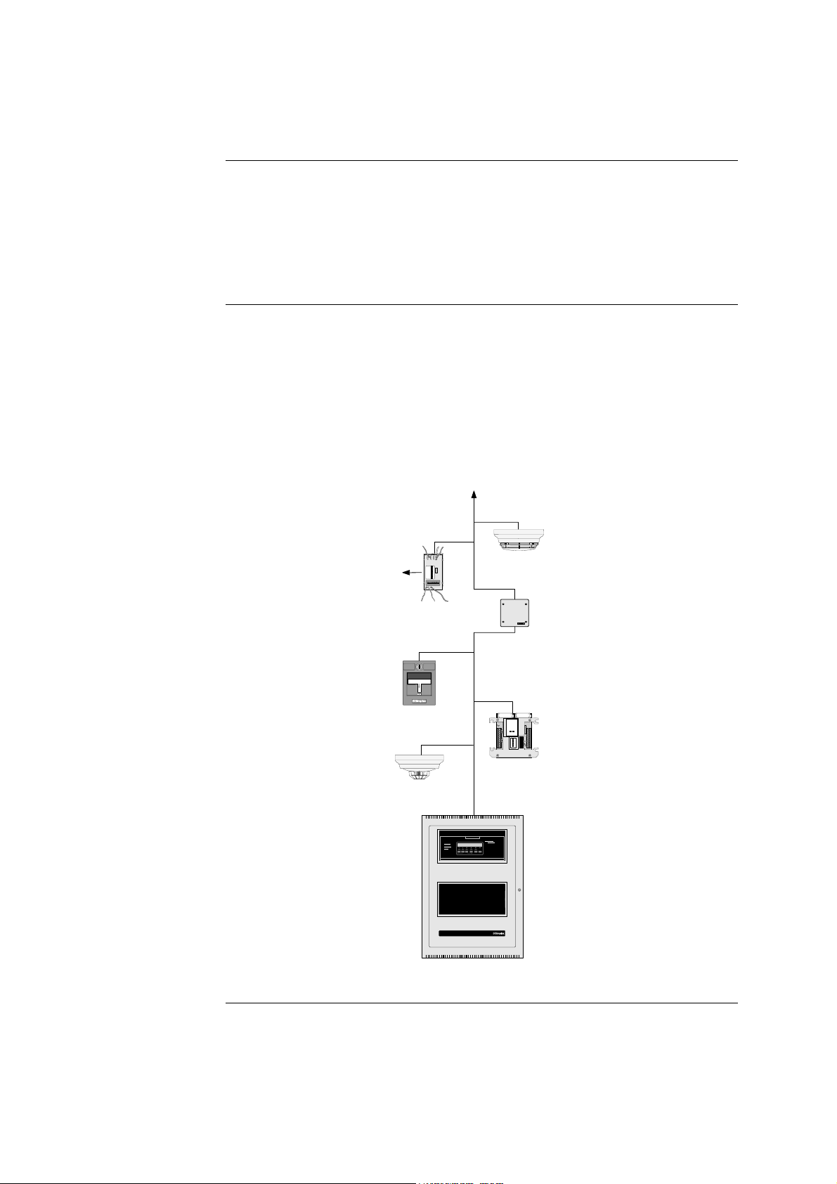
The standalone version of the 4100U is used for smaller or single-building applications. A
standalone system is ideally placed into a small building that requires a limited number of
notification appliances and initiating devices.
If a small building is being expanded, or if other buildings are being constructed in the
same general area (as in a campus application), the standalone 4100U can be expanded
into one of the larger systems described later.
The standalone 4100U uses one FACP (one, two, or three bays) containing the following:
• CPU
• System Power Supply for the 4100U (Universal Power Supply for the 4100)
• Optional slave cards
All appliances and devices are connected to that one FACP, as shown in Figure 1-1.
To additional IDNET devices, up to 250 total
to Device
1
A
2
D
3
D
4
R
5
E
51
6
S
9-
7
S
C
1 2 3 4 5 6
Smoke sensor
with base
Supervised IAM
Remote line
ALARMFIRE
PULL
ddressable
station
powered isolator
IN
33
21
21
21
IN
21
51
ST
90-
SI
90-
90-
ST
90-
33
9-
AL
91
M
91
91
AL
91
B
57
..I
63
PL
55
57
.
61
NS
.04
EX
.0
.01
IN
.04
TR
TI
ST
TE
UC
M
RU
28
.
E
C.
AD
1
DR
2
ES
3
S
4
I/O Module
Thermal sensor
with base
PULL TO OPE
EMERGENCY
12:35:15 am MON 29 JAN
ALA
ALA
ACKNO
SYSTEM IS NORMAL
SYS
SUPERVI
INSTRUCTI
LARM OR TROUBLE
- SYSTEM INDICATOR
TO
- PRESS "ACK" LOCATED
- REPEAT OPERATION UNTIL
TROU SILEN O
TO SILENCE
- PRESS "ALARM
TB
AC
TO RESTORE SYSTEM
- PRESS
- PRESS "ACK" TO
OPERATO
INTERFAC
PANEL
4100 FIRE ALARM CONTROL
Figure 1-1. Standalone 4100U System
1-3
Page 22

MINIPLEX Configuration
Overview
System Design
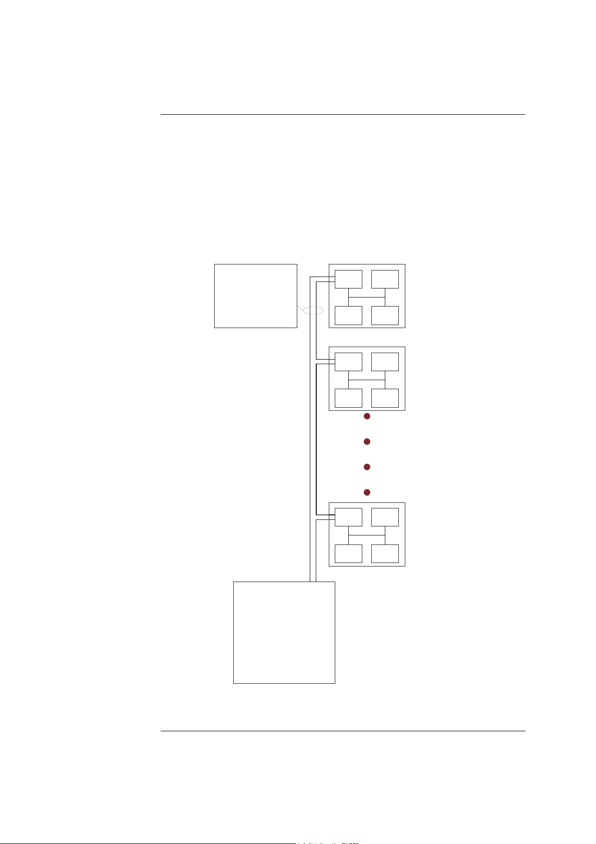
The MINIPLEX version of the 4100 Fire Alarm System, which is designed for
moderately larger applications than the standalone configuration, allows up to 1000
monitor and/or control points and 2000 annunciator points to be controlled by a single
FACP.
Like the standalone system, only one CPU is used. Remote Unit Interface (RUI) data, and
optionally power is distributed from the host panel to remote boxes called transponder
cabinets. The exact system design varies, depending on whether the system is a 4100 or a
4100U:
• 4100U: Transponder interface cards (TICs), located in transponder cabinets, take
the RUI data directly from the CPU motherboard and distribute it to modules nearby,
thereby expanding the system’s status from standalone to MINIPLEX.
• 4100: Remote interface cards (RICs), located in transponder cabinets, take the RUI
data and optionally power from the remote unit interface (RUI) card in the host panel
and distribute it to modules nearby, thereby expanding the system’s status from
standalone to MINIPLEX.
The MINIPLEX 4100 FACP must contain the following:
• CPU
• System Power Supply for the 4100U (Universal Power Supply for the 4100)
• 4100 only (non-4100U): Remote unit interface (RUI) Card
• Optional slave cards
Each transponder cabinet, meanwhile, must contain a Transponder Interface Card (TIC)
and any number of optional slave cards.
Continued on next page
1-4
Page 23
MINIPLEX Configuration, Continued
RUI Communication
The 4100 internal comms bus may be used to carry data from the CPU in the main cabinet
to expansion equipment in a co-located cabinet. 4100 data from the CPU may be routed to
remote cabinets (RTUs) in a MINIPLEX system by using the external RUI comms bus.
An RUI line, routed from either the CPU Motherboard in the 4100U, or the RUI card in
the 4100, allows the data to travel long distances. Once the RUI line terminates at a
remote cabinet, the TIC (4100U) or RIC (4100) in that cabinet distributes the CPU’s data
to the other modules within the cabinet.
Power has to be supplied locally within each RTU, or routed from the main FIP.
Figure 1-2, below, outlines this process in a typical MINIPLEX setup.
Risers from 4100U to
Remote Transponders
RUI
RUI I/F Slave
Slave Slave
RUI I/F Slave
Slave Slave
9th Floor
Transponder
Unit
6th Floor
Transponder
Unit
Transponders may be located
further apart (within the 2500'
limit) as called for by the
application requirements.
RUI I/F Slave
3rd Floor
Transponder
Unit
4100U
RUI Risers - 4 MAX (same channel)
(from CPU Motherboard or Remote
Unit Interface Card)
Slave Slave
Note:
Although not shown, nested
RUI is supported up to one
level deep.
Figure 1-2. MINIPLEX 4100U System
1-5
Page 24
Network Configuration
Overview
Hub and Star Configurations
The 4100 can be expanded to a network system by using network interface cards (NICs).
When a NIC is installed into a 4100 host panel, it is used to connect to other network
nodes. Nodes may consist of other host 4100 panels, or they may be completely different:
Graphical Command Centers (GCCs), and Visual Command Centers (VCCs) are all
examples of what could be used as nodes. A node is a self-sufficient CPU that controls
appliances and devices, which also has the capability of controlling and communicating
with other nodes.
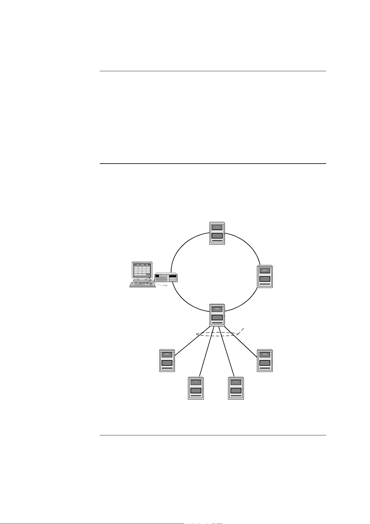
The network configuration supports two prevalent architectures (or wiring
configurations): hub (or ring), or star. A networked system can also use a combination of
the two.
The hub configuration consists of a main loop with nodes connected in a radial manner.
The star configuration consists of several nodes connected directly to one common node.
Physical bridge cards are used for the star configuration. Physical bridges reduce the
amount of wire that would otherwise be needed to connect all nodes in a loop, and
therefore cut down on system response time. A combination of the two styles is illustrated
in Figure 1-3.
Ring Topology
Graphic Command
Center (GCC)
Figure 1-3. Hub/Ring Configuration
Network Display Unit
(NDU) Hub Node
Distributed Remote
Node Locations
Physical Bridge Links
(Star Topology)
Continued on next page
1-6
Page 25
Network Configuration, Continued
Connecting Loops
Physical Bridge Link
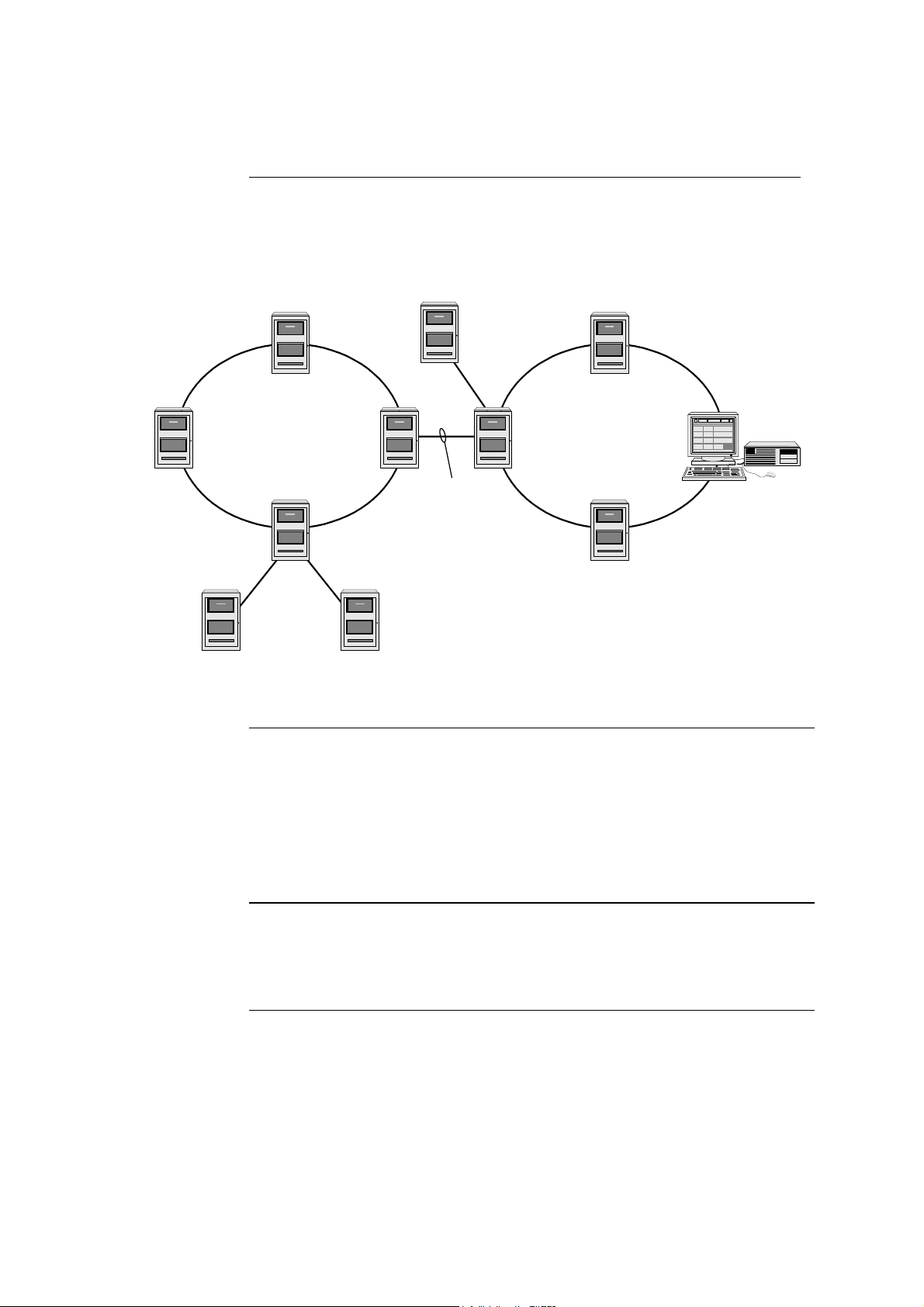
Network loops can be joined via physical bridge cards. There may be no more than two
Style 7 network loops (two hub configurations) connected in tandem. For every two
loops that are interconnected (using one physical bridge), there can be a maximum of
three physical bridges used in a star configuration. See Figure 1-4.
Remote
Node
Physical
Bridge
Link
Remote Loop
Hub Node
Physical Bridge Link
Physical Bridging
(Star Configuration)
Physical Bridge Link
Hub
Node
Local Loop
Graphic Command
Center (GCC)
Figure 1-4. Interconnected Loop Configuration
System Design
Network Communication
To be used as a network node, a 4100 panel must contain the following:
• CPU
• System Power Supply
• 4100 Network Interface Card
• Optional slave cards
Network communication is achieved via 4100-6014 or 4100-6035 Network Interface
Cards (NICs). Each network node requires a NIC. Once the FACP is a network node, it
may be programmed to be fully in control of other nodes, or to be fully passive, or
anywhere in between.
1-7
Page 26

4100 PIDs (Non-4100U)
The following is a list of existing 4100+/A cards and modules that may be used with
4100U.
• 4100-5004 8 AZF Monitor Zone
• 4100-0113 Dual RS232 Modem Interface
• 4100-0110 MAPNET 2 Addressable Loop
• 4100-3003 8 Relay Module
• 4100-4321 6 Supervised Relays
• 4100-3024 24 Relay Module
• 4100-0302 24 I/O Module
• 4100-0111 Quad Isolator Module
• 4100-0149 Modular Network Card (required 2 media cards)
• 4100-0142 Wired Media Card RS485
• 4100-0143 Fibre Optic Media Card
• 4100-0301 LED Switch Controller
Annunciation Modules
• 4100-0154 VESDA High Level Interface
• 4100-0157A 4100A PSU
• 4100-0451 Printer
• 4100-0301 64/64 LED/Switch Controller
• 4100-0302 24-Point I/O Graphic Interface
• 4100-0401 8-LED Display Card (Red LEDs)
• 4100-0402 16-Point Display Card (Red/Yellow LEDs)
• 4100-0403 8-Switch/8-LED Display Card (Momentary switches; red LEDs)
• 4100-0404 8-Switch/16-LED Display Card (Maintained switches; one red and
one green LED per switch)
• 4100-0405 8-Switch/16-LED Display Card (Maintained switches; one red and
one yellow LED per switch)
• 4100-0408 8-Switch/8-LED Annunciator Control Switch Module
• 4100-0450 Remote Panel LCD
1-8
Page 27

4100U Cabinet Part Identification Numbers (PIDs)
Overview
4100U Cabinets
4100U PIDs
Overview
This section lists all cabinet (back box) PIDs for the 4100U Fire Alarm System.
Empty cabinets with Doors (Cream Wrinkle)/ Number of bays
Number of bays that can be fitted:
• ME0447 18U x 210 Rack Cabinet, Window Door : 1-Bay
• ME0268 21U x 310 Rack Cabinet, Window Door : 1-Bay
• ME0255 28U x 310 Rack Cabinet, Window Door : 2-Bays
• ME0257 40U x 310 Rack Cabinet, Window Door : 3-Bays
• ME0454 18U x 210 Rack Cabinet, Solid Door : 1-Bay
• ME0269 21U x 310 Rack Cabinet, Solid Door : 1-Bay
• ME0265 28U x 310 Rack Cabinet, Solid Door : 2-Bays
• ME0267 40U x 310 Rack Cabinet, Solid Door : 3-Bays
This section lists the PIDs that are supported by the 4100U Fire Alarm System.
Assemblies, Cards & & Modules
The following is a list of assemblies, cards and modules used in 4100U:
• 566-084 Power Distribution Interface (ie the back-plane)
• 742-516 CPU Motherboard (566-227)
• 4100-7151 Master Controller (CPU Card 566-149)
• 4100-2300 Expansion Bay Assembly (includes the metalwork with the
PDI back- plane)
• 4100-6033 Alarm Relay Card (566-058. Small card plugged onto the SPS
and used to supply the Brigade I/F relays).
• 4100-3101 IDNET Module – 250 pt capacity (566-044)
• 4100-1288 64 LED/64 Switch Controller module w/mounting plate
• 4100-1289 64 LED/64 Switch Controller module
• 4100-1282 8 SW/16 LED red/yellow module
• 4100-1287 24 Switch/24 red LED module
• 4100-1284 8 Switch 16 red/green LED module
• 4100-1281 8 Switch 8 yellow LED module
Continued on next page
1-9
Page 28

4100U PIDs, Continued
• 4100-0625 Transponder Interface Card
• 4100-0160 Internet Interface Module (566-355).
• 4100-9848AU System Power Supply, Australian version.
• ME0456 Fan Control Module
Kits
Labels
The following kits are available:
• KT0419 A4 Document Holder, Stick-On, 3U High, Grey
• KT0446 4100U Expansion Bay
• KT0447 Expansion SPS, Bay Mounting
• KT0448 Fused DC Distribution Bd, XSPS AU Mounting
• KT0450 4100-4100U Upgrade, 19” RAC Mounting
• KT0452 IDNet Mounted on 4100 Interface Bracket
• KT0468 4100 MBd to 4100U Bay, Mounting Kit
• KT0469 A5 Document Holder, Stick-On, 3U High, Grey
Brigade Interfaces
• KT0199 19”, 3U ASE Mounting Bracket, plus
KT0207 ASE FAS Interface Loom
• FZ9028 19”, 3U AIU/PPU Mounting Bracket & Loom
LB0602 Operator I/F ISO/Test, Card
LB0605 Fan Control Zone Insert Card
526-873 Slide In Label, LED Switch Module, 1 Sheet of 6
4100-1294 Module Slide In Labels, Panel Set
Looms
LM0309 4100U Mains Lead With Filter
LM0310 4100U Battery Lead Set, 18U-21U (1976-132-1)
LM0311 4100U Battery Lead Set, 28U-40U (1976-132-2)
734-008 Harness, Power Comms, 4 Way, 2ft Length
734-075 Harness, Power Comms, 4 Way, 8ft Length
SX0039 Sw/LED Module Ribbon Cable, 26 Way, 2in
SX0052 Sw/LED Module Ribbon Cable, 26 Way, 6in
1-10
Page 29

Introduction
Chapter 2
Installing 4100U FACP Components
4100U cabinets are available in one-, two-, and three-bay sizes. Each can be equipped
with a solid or perspex door. This chapter describes how to mount all types of 4100U
cabinets to a wall, and how to mount system card bays into the cabinets, modules to bays,
etc.
FACPs are assembled to order within the factory. Steps 2 to 6 below are therefore not
typically required in the field, but are included in case of in-field system expansion.
The section Introduction to FACPs describes the various components that make up the
FACP.
The assembly drawings 1976-136, 1976-137 are included in the appendix of this manual
for reference.
In this Chapter
Refer to the page number listed in this table for information on a specific topic.
Topic See Page #
Introduction to FACPs (4100U)
Step 1. Mounting Cabinets (4100U)
Step 2. Mounting Card Bays to Cabinets (4100U)
Step 3. Configuring Cards (4100U)
Step 4. Interconnecting Modules and Bays
Step 5. Installing Modules into Expansion Bays (4100U)
Step 6. Installing LED/Switch Modules into Expansion Bays
(4100U)
The Terminal Block Utility Module (4100U)
2-2
2-9
2-9
2-10
2-11
2-15
2-20
2-27
2-1
Page 30

Introduction to FACPs (4100U)
Overview
CPU Bay
4100U FACPs cabinets contain the CPU, operator interface, system power supply (SPS),
backup batteries, and any additional modules that the panel requires. The FACP is the
central hub (often referred to as a host panel) of a standalone or MINIPLEX fire alarm
system. In a networked system, the FACP can be connected to other system FACPs, so
that each host panel is a node on the network.
In the standard (USA) version of 4100U the CPU bay contains an SPS, the Master
Motherboard with CPU Daughter card, but no PDI to which 4” x 5” cards (e.g. IDNet
card) can be fitted. Also, it has the Operator Interface (I/F) on its front, so no switch/LED
display modules can be fitted to it.
In the Australian version the SPS is fitted to a bracket behind a side-hinged 4U door that
has the Operator I/F on it. The Master Motherboard (i.e. CPU Motherboard) is fitted to
the right hand side of an expansion bay mounted directly below. This bay has a PDI
fitted so can house 4”x 5”cards and Switch/LED Display Modules.
Continued on next page
2-2
Page 31

Introduction to FACPs (4100U), Continued
A
A
A
K
K
A
Master Motherboard
The 4100U Master motherboard that houses the CPU card is central to the 4100U system.
It mounts in the first bay, occupying four inches of space on the right hand side. Neither
has a card address DIP switch (the CPU is address 0).
NETWORK WIRED MEDIA/ RS-232
TERMINAL BLOCK (TB3)
RUI TERMINAL BLOCK (TB2)
XMIT RTS RCV CTS GND
1
RS-232/NETWOR
CARD PORT 1
JUMPER (P10)
COMMS CONNECTOR TO
OPTION MOTHERBOARD
(P8)
HEADER CONNECTOR TO
OPTION MOTHERBOARD
(P3)
RUI RUI SHLD RUI RUI
B+ B- A+
55
1
-
RUI CLASS A
TROUBLE (LED1)
RUI PRIMARY SHORT
TROUBLE (LED2)
RUI SECONDARY
SHORT TROUBLE
(LED3)
RUI COMM
EARTH SHIELD
JUMPER (P9)
POWER/COMM TO
SYSTEM POWER
SUPPLY (P1)
BUS CONNECTOR
(J1) (Reserved for
future use)
POWER CONNECTOR TO
OPTION MOTHERBOARD
(P7)
NETWORK DAUGHTER CARD
CONNECTOR
(J2)
RS-232/NETWOR
CARD PORT 2
JUMPER (P11)
NETWORK WIRED MEDIA/ RS-232
TERMINAL BLOCK (TB1)
Figure 2-1. Master (CPU) Motherboard (566-227)
8
XMIT RTS RCV CTS GND 24C RSRVD
PIEZO
CPU DAUGHTER CARD
CONNECTOR (J3)
POWER/COMMS TO
POWER/COMMS TO
POWER/COMMS TO
1
Continued on next page
DJACENT BAY (P4)
DJACENT BAY (P5)
DJACENT BAY (P6)
2-3
Page 32

Introduction to FACPs (4100U), Continued
Master Controller Daughter Card
The master controller daughter card mounts onto the master motherboard. The master
controller daughter card contains a service port, a direct drive user interface connection,
and a port for a service modem.
MODEM
SERVICE MODEM
CONNECTOR (P4)
CONNECTOR TO CPU
MOTHERBOARD (P9)
BAT ON BAT OFF
BATTERY BACKUP
ON/ OFF JUMPER (P3)
2
LED1 LED2 LED3
SERVICE PORT DISPLAY
SERVICE PORT
COMM JUMPER (P1)
CPU BOOTLOADER LEDs
(LED1 – LED4)
TROUBLE LED (LD5)
SERVICE PORT (P5)
DIRECT-DRIVE
DISPLAY PORT (P6)
CPU CARD
BD ASSY
566-149
TROUBLE LED (LED5):
OFF: No trouble.
FLASHING: CPU has power but the software is
failing to hit the watchdog
ON: The 5 V is outside the acceptable range
WARM START
SWITCH (SW1)
Figure 2-2. Master Controller Daughter Card (566-149)
Continued on next page
2-4
Page 33

Introduction to FACPs (4100U), Continued
Master Controller Daughter Card LEDs
The master controller daughter card LEDs indicate Bootloader status as shown in the
table below.
Table 2-1. Master Controller LEDs 1 through 4
Status
Condition
Bootloader
Initialization
Bad Master
CRC or No
Master Present
Diagnostic Fail –
RAM
Diagnostic Fail –
Bootloader CRC
Downloading
Master
Downloading
CFIG
Downloading
MsgLib
Downloading
BootLoader
Download
Successful
LED4 LED3 LED2 LED1
On (0.25s),
Off (0.25s)
On Off Off Off
On Off Off On
On Off On Off
On Off On On
On On Off Off
On On Off On
On On On Off
On On On On
On (0.25s),
Off (0.25s)
On (0.25s),
Off (0.25s)
On (0.25s),
Off (0.25s)
Continued on next page
2-5
Page 34

Introduction to FACPs (4100U), Continued
Operator Interface
Additional CPU Bay Modules
The operator interface lets a user operate the panel. It provides alarm, trouble, and isolate
status alerts, and lets the user review historical logs and perform diagnostics.
Figure 2-3. Operator Interface
The CPU bay can be equipped with many additional types of modules. The cards listed
below are limited to the CPU bay only.
4100-6030 Service Modem Card. CPU mezzanine card. Provides a connection to remote
PCs for diagnostics and programming purposes. (Not approved for use in Australia).
4100-6014 Modular Network Interface Card (NIC). A daughter card that mounts to the
CPU motherboard. Performs 4100 networking operations. May be installed with the
4100-6056 Wired Media Card and/or the 4100-6057 Fiber Media Card.
Expansion Bays
An FACP always has the CPU in the first bay, but it may have further expansion bays.
Expansion bays contain a variety of additional modules that the system might require.
Continued on next page
2-6
Page 35

Introduction to FACPs (4100U), Continued
Y
K
A
System Power Supply (SPS)
In the USA, a number of variants of power supply are available, e.g. SPS, RPS, XPS,
XCharger each with different portions of circuitry (eg NACs, Battery Charger, IDNet)
fitted or not fitted. In Australia, only one variant (SPS) is currently available, and it has
hardware and software that are specific to Australia. This unit is used as the main power
supply, but may also be fitted directly to a card bay as an expansion supply.
The system power supply (SPS) is mains powered and has backup batteries that get
switched in on mains failure. It is the initial power source for the CPU and the host
cabinet. The SPS provides 24V card power to the CPU motherboard and the other cards.
It also supplies 24V power on a separate bus to the outputs, e.g. Notification Appliance
Circuits (NACs).
The SPS also has three on-board NACs that support reverse polarity supervision. It
provides an IDNet channel, auxiliary power, an auxiliary relay, and it mounts and drives
the Alarm Relay Card.
The SPS performs functions such as brownout detect, battery transfer, battery recharge,
earth fault detection, and power limiting of outputs. It provides voltage and current
information to the CPU card, which can then be displayed at the user interface.
IDNET TERMINAL BLOCK (TB1)
NAC TERMINAL BLOCK (TB2)
POWER/COMM TO
NEXT PDI (P6)
IDNET SHIELD JUMPER
(P2)
CITY/RELAY CARD
TROUBLE INDICATION
JUMPER (P3)
DEVICE ADDRESS
SWITCH (SW1)
AUXILIARY RELA
TERMINAL BLOC
(TB4)
AUXILIARY POWER
TERMINAL BLOCK
(TB3)
CITY CARD
CONNECTOR (P7)
Figure 2-4. System Power Supply
CITY / RELAY CARD
MOUNTING AREA
POWER/COMM TO
CPU
MOTHERBOARD
(P8)
BATTERY
CONNECTORS:
P4
P5
EARTH
FAULT
MONITOR
JUMPER (P1)
C
CONNECTOR
(under board)
Continued on next page
2-7
Page 36

Introduction to FACPs (4100U), Continued
System Power
The Power Distribution Interface (PDI)
POWER/COMMS
CONNECTORS
POWER SOURCE
JUMPERS
(P4, P5)
INTERFACE
CONNECTORS
(P1-P3)
AUDIO
(P6, P7)
The FACP is powered by the SPS (System Power Supply), which gets its primary power
from the AC mains and its secondary power from the backup batteries.
The 24Vdc bulk power on the SPS is unregulated, and is divided into three feeds, i.e. 24V
Card, 24V Signal, and 24V Aux Power. 24V Card which supplies the cards, and Aux
power, which is accessible on screw terminals, are each rated at 2A and protected by a
PTC. The 27.3V regulated battery charger is powered from the bulk supply and is
switched off during alarm. The batteries only get connected to the bulk supply when the
mains supply fails. The charger has two programmable options of rating, 1.4A for 618Ahr (called little-uns), and 3.3A for batteries above 18Ahr (called big-uns).
The “heavy” 24V Signal feed is only accessible via the NACs on the SPS, or via a wire
harness.
IMPORTANT: AC power must be provided to the 4100U from a dedicated
branch circuit.
In expansion bays, power and data are distributed via the power distribution interface
(PDI). The PDI is a wiring board with eight card slots, each of which can accommodate a
4-inch (102 mm) x 5-inch (127 mm) slave card. If motherboards are used, they must be
mounted over the PDI using metal standoffs.
Standards cards, e.g. IDNet, plugged onto the PDI access only the 24V Card supply.
If an XSPS is plugged onto the PDI, then the 24V Signal Bus is also powered. This is
required for the 4100MXP which uses card power to power its electronics, but signal
power to supply the 40V loop.
4100 POWER DISTRIBUTION INTERFACE
ASSY 566-084
Figure 2-5. The Power Distribution Interface (PDI)
2-8
Page 37

Step 1. Mounting Cabinets (4100U)
Overview
The important aspects of mounting the cabinet are:
Access for the operator;
Height of displays and controls;
Free space for door opening;
Cable entry for field wiring.
Refer to AS1670 for the height requirement and minimum access requirements.
In general, 18U – 28U cabinets will need to be wall mounted. Mounting holes and cabinet
dimensions are shown in drawing 1919-22b.
Door opening left/right should be specified with the order. The cabinets are symmetrical,
top to bottom, so door opening can be swapped by removing the equipment, rotating the
cabinet 180°, then re-fitting the equipment.
Step 2. Mounting Card Bays to Cabinets (4100U)
Overview
FACPs are ordered from the factory with bays and cards fitted as per the panel order
spreadsheet.
Additional mounting bays may be ordered as KT0447 which includes the 19” rac
mounting brackets and earth loom.
Attach each mounting bracket to the two studs in each front corner to achieve the format
shown below. Fit M6 cage nuts to the appropriate 19”rack holes, then attach the bay
using M6 countersunk screws.
←
Mounting Bracket
←
Bay Front
Figure 2-6. Bracket Mounting
Refer to the assembly drawings in the Appendix.
2-9
Page 38

Step 3. Configuring Cards (4100U)
Overview
Master Motherboard Configuration
Master Controller Daughter Card Configuration
The CPU, SPS, and all other modules to be mounted in the FACP cabinets must be
configured to operate correctly in the system via their DIP switch and jumper ports. This
section describes the hardware configuration for the CPU and SPS, since they will always
be used in the CPU bay.
The CPU motherboard must be jumpered as follows:
P9 determines whether the RUI SHIELD signal is connected to 24 C or Earth.
• Position 1 – 2: SHIELD to 24 C (default). Set to this position unless the system
uses a TrueAlert Power Supply.
• Position 2 – 3: SHIELD to Earth. Set to this position only if the system uses a
TrueAlert Power Supply.
Note: Some devices that connect to RUI have inherently grounded shield
terminals, in which case 24 C cannot be used. If 24 C is used, a
Negative Ground Fault will occur.
P10/P11: P10 is associated with Port 1 and P11 is associated with Port 2. P10 and P11 are
used to set the CPU motherboard up to be attached to either a network card or a RS232/2120 card.
• Position 1 – 2: Network card (NIC) attached to CPU motherboard (default).
• Position 2 – 3: RS-232/2120 card attached to CPU motherboard.
The master controller daughter card must be jumpered as follows:
P1 is used for engineering diagnostics (COMLAB).
• Position 1 – 2 : Download or no connection.
• Position 2 – 3 : Diagnostic mode.
P3 configures the RAM battery as ON or OFF.
• Position 1 – 2 : ON.
• Position 2 – 3 : OFF.
SPS Configuration
The SPS must be configured as follows:
SW1: Using DIP switch SW1, set the SPS device address. Use the address table in
Appendix A.
P2: If the SPS IDNet outputs are being used, you may change P2 to configure the IDNet
shield connection.
• Position 1 – 2 (bottom) : Connects the shield to 0 V (default).
• Position 2 – 3 (top) : Connects the shield to earth ground.
P3 configures relay 3 on the 4100-6033 Alarm Relay Card.
• Position 1 – 2 (top) : Removes fault monitoring on relay 3 (default).
• Position 2 – 3 (bottom) : Makes relay 3 activate when there is a fault.
P1: Earth connect jumper.
• Position 1 – 2 (rhs): Enables Earth fault monitoring. Set to this position unless the
system uses a TrueAlert Power Supply under common 0 V.
• Position 2 – 3 (lhs): Disables Earth fault monitoring. Set to this position only if the
system uses a TrueAlert Power Supply under common 0 V.
Continued on next page
2-10
Page 39

Step 3. Configuring Cards (4100U), Continued
PDI Configuration
P4/P5: The PDI can be configured to draw its power from different sources via P4 and
P5.
• To draw power from an XPS on the PDI, set jumpers on P4 and P5 to position 2
– 3.
• To draw power from P1 (from the previous PDI or SPS), set jumpers on P4 and
P5 to position
1 – 2 (default).
• To remove power from the PDI, remove the jumper from P4.
Configuring Other Cards
Refer to the appropriate installation instructions to configure other cards that are located
in CPU and expansion bays. The 4100U ones are included in this manual. Refer to
Appendix D for a list of publications.
Step 4. Interconnecting Modules and Bays
Overview
Each card has to be interconnected with every other card in its bay. At the same time,
bays in the FACP also have to be connected together. Read this section to ensure that
cards and bays are interconnected. Refer also to drawings 1976-136 and 1976-137.
Guidelines
Review the following guidelines before interconnecting modules and bays.
• The SPS provides 24 V power to the CPU motherboard.
• The CPU motherboard provides 8 V (3 A capacity) for use by Legacy 4100 slave
cards. 24 V card power is routed through the motherboard for slave card use.
• 4100 internal comms and power are harnessed to other bays. Do not connect the 8 V
at P7 to an 8 V converter on a Goldwing or remote interface card.
• 24 V Card power from the SPS is rated at 2 A.
• The 4-wire coms and power harness carries only the 24 V Card supply to a PDI, and
not the 24V Signal supply.
• Some of the wire harnesses supplied with cards are not required. It is recommended
to store these spare harnesses in case of future requirements.
Continued on next page
2-11
Page 40

Step 4. Interconnecting Modules and Bays, Continued
Card Interconnections in the CPU Bay
Card Interconnections Within Expansion Bays
Basic Bay-To-Bay Interconnections
Use the following directions to connect the CPU to the SPS and other motherboards.
1. Connect P3 on the SPS to P1 on the CPU motherboard using the 8 wire harness
with eight-position Molex minifit connector (provided).
2. Make sure the 10 way, right angle header, connector P3 on the CPU is secured to
J1 on the next motherboard to the left. Repeat this for the third (leftmost)
motherboard, and on if applicable.
The power distribution interface (PDI) mounted to the back of each expansion cabinet
carries 24V Card power and data to each 4”x 5” card.
Refer to “Step 7: Installing Modules into Expansion Bays (4100U)” for instructions on
mounting 4”x 5” cards to the PDI. Also bear in mind the following variations:
• In a remote expansion cabinet, a transponder interface card (TIC) requires additional
interconnections. This occurs in MINIPLEX systems. Refer to Chapter 3.
• Regular motherboards require non-PDI interconnections to each other and to the
CPU. Refer to “Step 5: Installing Modules into Expansion Bays (4100U).”
The 4 wire harness 734-008 is used to carry 24V Card power and coms from bay to bay.
Connector P1 on the PDI receives power from the previous PDI or from P6 on the SPS
(or alternatively from P7, P8 on the CPU Motherboard). P2 on the PDI is used to carry
power and coms to a 64/64 Controller. P3 is used to carry power and coms to the next
PDI.
Jumpers P4 and P5 on the PDI are set to positions 2-3 (right) to provide card power
to the bay only if an XPS is fitted to the PDI. Jumpers P4 and P5 are set to positions
1-2 (left) to provide card power to the bay from P1 on the PDI.
Note: Interconnections can become more involved if 4100 motherboards are
used. Refer to “Step 5: Installing Modules into Expansion Bays (4100U)”
if this is the case.
Continued on next page
2-12
Page 41

Step 4. Interconnecting Modules and Bays, Continued
Basic Bay-To-Bay
Interconnections
(continued)
HARNESS
734-008
Connecting to Motherboards
Figure 2-7, below, shows the interconnections between three bays in a host panel.
P1
P2
P3
P4
P5
P6
P7
P1
P2
P3
P4
P5
P6
P7
4100 POWER DISTRIBUTION INTERFACE
ASSY 566-084
4100 POWER DISTRIBUTION INTERFACE
ASSY 566-084
From Previous PDI
P3
Figure 2-7. Bay-to-Bay Interconnections
Panels with motherboards on the left side of the expansion bays require some non-PDI
connections. If you need to connect a harness to a motherboard, refer to Figure 2-8 and
follow these steps. Make sure to route the power and communication wiring on the left
side of the bay.
1. Connect one end of the 733-525 Harness to a motherboard in an adjacent bay.
If the adjacent bay is a CPU bay with no additional motherboards, connect the
harness to the P8 and P7 connectors of the CPU motherboard.
• Insert the harness connector with the blue wire into the P8 connector. Note that
the P8 connector has eight pins. Insert the harness connector on either the top
four pins or the bottom four pins, not in the middle.
• Insert the harness connector with the white wire into the P7 connector. Note that
the P7 connector has eight pins. Insert the harness connector on either the top
four pins or the bottom four pins, not in the middle.
If the adjacent bay is an expansion bay or a CPU bay with additional motherboards,
connect the harness to the P2 and P3 connectors of the motherboard installed in the
leftmost slot. Connect the harness as follows:
• Insert the harness connector with the blue wire into the P2 connector. Note that
the P2 connector has eight pins. Insert the harness connector on either the top
four pins or the bottom four pins, not in the middle.
• Insert the harness connector with the white wire into the P3 connector. Note that
the P3 connector has eight pins. Insert the harness connector on either the top
four pins or the bottom four pins, not in the middle.
Continued on next page
2-13
Page 42

Step 4. Interconnecting Modules and Bays, Continued
Connecting to
Motherboards
(continued)
2. Connect the other end of the harness to the leftmost motherboard in the next bay,
as described below. Make sure to route the wiring on the left side of the bay.
• Insert the harness connector with the blue wire into the P2 connector. Note
that the P2 connector has eight pins. Insert the harness connector on either
the top four pins or the bottom four pins, not in the middle.
• Insert the harness connector with the white wire into the P3 connector. Note
that the P3 connector has eight pins. Insert the harness connector on either
the top four pins or the bottom four pins, not in the middle.
733-525 Harness
Connector with
Blue Wire Goes
to P2
Connector with
White Wire Goes
to P3
Figure 2-8. Power and Communication Wiring for Motherboards
2-14
Page 43

Step 5. Installing Modules into Expansion Bays (4100U)
Overview
Placement Guidelines
This section contains guidelines and instructions on installing 4”x 5” cards and traditional
motherboards into 4100U card bays.
IMPORTANT: This section applies to aftermarket modules for expansion bays
only. If you do not need to install any aftermarket modules at all,
and if you have followed Steps 1 through 6, you have completed
the panel installation and can apply AC power.
Refer to the following guidelines before mounting 4” x 5” cards and/or motherboards to
an expansion bay.
• Each expansion bay assembly includes a chassis, two end supports, one LED/switch
frame, and a power distribution interface (PDI) board.
• An expansion bay holds up to eight 4” x 5” modules. A double-size module, such as
the expansion power supply (XPS), takes up two blocks of space as shown below.
The Australian SPS takes up four blocks of space (note, the double sized XPS is not
currently available for Australia).
• Cards should be added from right to left if an XSPS is fitted.
Block A Block C
I/O Wiring I/O Wiring I/O Wiring
Block E Slots 7 + 8
I/O Wiring
4" (102 mm) x 5" (127 mm)
Module
Power Distribution Interface (PDI)
4" (102 mm) x 5" (127 mm)
Module
I/O Wiring I/O Wiring I/O Wiring
Block B Block D
4" (102 mm) x 5" (127 mm)
Module
4" (102 mm) x 5" (127 mm)
Module
4" (102 mm) x 5" (127 mm)
Module
4" (102 mm) x 5" (127 mm)
Module
Block F
Expansion Power
Supply
(XPS)
(Note. Australian SPS is 4 slots wide. XPS is not available in Australia.)
Figure 2-9. Expansion Bay 4”x 5” Card Placement
Continued on next page
2-15
Page 44

Step 5. Installing Modules into Expansion Bays (4100U), Continued
Placement
Guidelines
(continued)
• Motherboards can be installed on top of the PDI in expansion bays. The data and
power that would normally be bussed via the PDI is instead routed across the boards
via ribbon cable from one board to the next.
• Up to eight 2” (51 mm) x 11 ½” (292 mm) motherboards can be installed in an
expansion bay if no 4”x 5”modules are installed in the bay, and if the pins on the
left connector (usually P1) on the leftmost motherboard are removed.
Motherboards are mounted on top of the PDI in expansion bays. The data and power
that would normally be bussed via the PDI is instead routed across the boards via
ribbon cable from one board to the next.
• Motherboards should be added from left to right.
• Relay motherboards must be the rightmost motherboards.
• In the first bay of an FACP, the CPU motherboard is the right most motherboard, and
other motherboards are fitted to its left side.
• The CPU motherboard generates the 8V supply required for 4100A motherboards. It
also has the 4100A style Molex connectors to which a harness can be fitted as per Fig
2-8.
Slot 2 Slot 3 Slot 4 Slot 5 Slot 6 Slot 7 Slot 8Slot 1
This Slot
Must
Remain
Empty
4100 Option Bd
4100 Option Bd
4100 Option Bd
4100 Option Bd
4100 Option Bd
4100 Option Bd
4100 Option Bd
Power Distribution
Interface
This slot cannot contain a
motherboard unless the pins
on P1 (or leftmost pin
connector) are removed.
Figure 2-10. Expansion Bay Motherboard Placement
Up to eight 2” (51mm) x 11 ½” (292 mm) motherboards can be
mounted in an expansion bay. Seven motherboards fit into Slots
2 through 8; the eighth can be added in Slot 1 if its leftpost pins
are removed.
Continued on next page
2-16
Page 45

Step 5. Installing Modules into Expansion Bays (4100U), Continued
Placement
Guidelines
(continued)
• As shown in the figure below, motherboards can be installed alongside
4”x 5” cards, if necessary.
Position
Slot 1 Slot 2 Slot 3 Slot 4
PDI
No Boards
Allowed
in
This Slot
4100 Option
4100 Option
4100 Option
This slot cannot contain a motherboard unless the pins
on P1 (or leftmost pin connector) are removed.
Block E Slots 7 + 8
5
I/O Wiring
4" (102 mm) x 5" (127 mm)
Module
4" (102 mm) x 5" (127 mm)
Module
I/O Wiring
Position
Block F
6
Position
7 & 8
I/O Wiring
Expansion Power
Supply
(XPS)
(Note. Australian SPS is 4 slots wide. XPS is not available in Australia.)
Figure 2-11. Mixed Module Placement
Continued on next page
2-17
Page 46

Step 5. Installing Modules into Expansion Bays (4100U), Continued
Installing 4” X 5” Cards
4”x 5” CARD
#6 SCREWS
The power distribution interface (PDI) is mounted to the back of each expansion cabinet.
The PDI contains slots for up to eight 4”x 5” slave cards. Since the PDI carries power and
data across the entire bay, it solves most interconnection issues, especially between
4”x 5” cards.
Use the following instructions and the figure below to mount 4”x 5” slave cards to an
expansion cabinet.
1. Screw two standoffs and washers to the appropriate holes in the back of the
cabinet. These holes must line up with the screw holes in the 4”x 5” card. See
Figure 3-24.
2. Plug the 4”x 5” card into the appropriate blind mating connector. Seat the card
firmly onto the PDI when installing to ensure complete insertion of the power
connector into the PDI.
3. Secure the top of the card to the standoffs with two #6 torx screws and washers.
WASHERS
STANDOFFS
SCREW
RETAINERS
PDI CONNECTOR
(reverse side)
PDI
Figure 2-12. Slave Card/PDI Connection
Continued on next page
2-18
Page 47

Step 5. Installing Modules into Expansion Bays (4100U), Continued
Installing
Motherboards
Use the following procedure when installing motherboards in an expansion bay. Start
with the second slot from the left and fill to the right. The mounting items are available
as KT0468.
1. Orient the motherboard with the connector labeled J1 on the right and the header
labeled P1 on the left.
2. Attach four metal threaded standoffs and lockwashers into the screw holes on the
chassis.
3. Attach two grey plastic standoffs to the motherboard socket mounting screws.
4. Secure the motherboard to the standoffs using four #6 torx screws as shown below.
WARNING: Note that a 4100 Motherboard with daughter card cannot be fitted
directly behind a 64/64 LED/Switch Controller. The same applies
to the modules made on the bay mounting bracket (FA2255), e.g.
ME0426 T-Gen.
METAL
STANDOFFS
SCREW HOLES
PLASTIC STANDOFFS
#6 SCREWS
SCREW HOLES
LOCKWASHERS
Figure 2-13. Installing the Motherboard in a 4100U Expansion Bay
2-19
Page 48

Step 6. Installing LED/Switch Modules into Expansion Bays (4100U)
Overview
The LED/switch user interface consists of a variety of modules, mounted to the front of
an expansion bay, which are configured via the 4100 Programmer. Each display module
contains between 8 and 24 switches and LEDs, each one separately configurable.
User interface functionality is driven by the 64/64 LED/Switch Controller Card, which
mounts behind two of the display modules (typically in positions 3 and 4). The varieties
of modules are as follows:
• 4100-1288 LED/Switch Controller Card with mounting plate.
• 4100-1289 LED/Switch Controller Card (no mounting plate; mounts on extra
space of 4100-1288).
• 4100-1280 8-Switch/8-LED Display Card. With red LEDs.
• 4100-1281 8-Switch/8-LED Display Card. With yellow LEDs.
• 4100-1282 8-Switch/16-LED Display Card. With one red and one yellow LED
per switch.
• 4100-1283 8-Switch/16-LED Display Card. With two yellow LEDs per switch.
• 4100-1284 8-Switch/16-LED Display Card. With one red and one green LED
per switch.
• 4100-1285 16-Switch/16-LED Display Card. With red LEDs.
• 4100-1286 Hands Off Auto (HOA) Switch Display Card. Provides 24 switches
and 24 LEDs. The HOA uses an overlay to group every 3 switches together,
denoting on, off, and automatic control of smoke control components. For every
group of 3 switches, there are 3 LEDs (green-red-green).
• 4100-1287 24-Switch/24-LED Display Card. With red LEDs.
• 4100-1279 2” Blank display cover module to cover empty front panel space
• 4100-1294 Slide-In Label Kit - one per 4100U cabinet
• 4100-1276 8-Pluggable LEDs with 8 red LEDs
• 4100-1277 16-Pluggable LEDs with alternating red and yellow LEDs
• 4100-1278. 16-Switch/16-LED with alternating red and yellow LEDs, one per
switch
• 4100-1295 Hands Off Auto (HOA) switch display card. Provides 24 switches
and 24 red LEDs.
• 4100-1296 8-Switch/16 LED Display Card. With one green and one yellow
LED per switch.
• 4100-9843 Pluggable LED Kit, 8 Yellow LEDs
• 4100-9844 Pluggable LED Kit, 8 Green LEDs
• 4100-9845 Pluggable LED Kit, 8 Red LEDs
• ME0456 Fan Control Module
Continued on next page
2-20
Page 49

Step 6. Installing LED/Switch Modules into Expansion Bays (4100U),
Continued
The LED/Switch User Interface
Below is an illustration of a LED/switch bay from the user’s perspective.
Figure 2-14. LED/Switch Modules
LED/Switch Controller Card
The LED/switch controller card is a 4100 slave that mounts behind two LED/switch
modules. The LED/switch controller handles up to 64 switches and 64 LEDs on the
modules and communicates their status to the 4100 CPU. When a button is pressed on a
module, the controller acknowledges the signal and reacts according to how that switch
was configured via the 4100 Programmer.
REMOTE ANNUNCIATOR
JUMPER (P1)
GND1
LED/SWITCH DISPLAY
CONNECTOR
(P4; reverse side)
COMM LOSS LED (LED1)
ADDRESS DIP
SWITCH (SW1)
LED1
COMM
LOSS
SW1
P1
1
2
3
4
5
6
7
8
POWER/COMMS
CONNECTORS
Figure 2-15. LED/Switch Controller
(P2)
(P3)
P2
12
P3
12
Continued on next page
2-21
Page 50

Step 6. Installing LED/Switch Modules into Expansion Bays (4100U),
Continued
LED/Switch
Controller Card,
(continued)
LED/Switch Modules
Configuring the LED/Switch Controller Card
Activating the Communication Loss Feature
If more than 64 LEDs or 64 switches are used, a second controller may be installed.
LED 1. This LED illuminates if communication loss between the controller and the CPU
occurs. It is independent of jumper P1 (which configures different communication loss
features).
All types of modules are mounted to the front of a bay, and are connected to each other
via a ribbon cable. Each module operates by the same rules: when a button is pressed, the
controller card sends the CPU the information, and the event programmed for that button
occurs.
The 64/64 LED/switch controller requires physical configuration, but the LED/Switch
modules do not. Configuration consists of setting jumper P1 and setting the device
address. Device Address is covered in Appendix A.
If the LED/switch controller is used in a remote annunciator, it can make the LED/Switch
modules annunciate a communication loss condition. If communication loss occurs when
this setting is activated, LED 1 of the first connected display card illuminates, and the
piezo on the LED/switch controller sounds. The indication is silenced via the
corresponding switch (switch 1 on the first display card).
Use jumper port P1 to activate or deactivate the communication loss feature.
• Position 1 - 2 deactivates the feature (default).
• Position 2 - 3 activates the communication loss feature.
Continued on next page
2-22
Page 51

Step 6. Installing LED/Switch Modules into Expansion Bays (4100U),
Continued
Mounting LED/Switch Modules to the Expansion Bay
LOCKWASHERS
Refer to the figure below to mount the display cards to the front of the expansion box.
ADDITIONAL
LED/SWITCH
#6 UNC NUTS
CONTROLLER
GROUND
CONNECTION
GROUND
CONNECTION
Figure 2-16. LED/Switch Card Mounting
Continued on next page
Controller assemblies
can only be installed
into these two slots
2-23
Page 52

Step 6. Installing LED/Switch Modules into Expansion Bays (4100U),
Continued
Mounting the Controller Card Assembly
Refer to the figures and instructions below to mount the controller card assembly to the
back of one of the LED/switch cards.
4. Use four 322-123 Nuts and four 268-009 Washers to secure the 637-141 Bracket
to the inside front of the expansion box. Note that there are only two locations
where the bracket can be mounted, as shown in Figure 2-16.
5. Attach the header connector on the back side of the controller (P4) to the
connector on the back side of one of the LED/switch modules.
6. Secure the controller card to the board using four #6 screws, as shown in Figure
5.
Changing Display Card LEDs
Figure 2-17. Controller Card Mounting
WARNING: The 64/64 Controller Card cannot be mounted directly in front of a
4100 Motherboard or a Bay mounting bracket such as one that
mounts a T-Gen.
The 4100-1276 LED display card contains eight red LEDs and the 4100-1277 card
contains 16 alternating red/yellow LEDs. The LED colors may be configured differently,
as described in this section.
Only the following LEDs are to be used to change color configurations. LEDs are
available in sets of eight, as follows:
• 4100-9843 (yellow)
• 4100-9844 (green)
• 4100-9845 (red)
Continued on next page
2-24
Page 53

Step 6. Installing LED/Switch Modules into Expansion Bays (4100U),
Continued
Changing Display
Card LEDs,
(continued)
Interconnecting Cards
Figure 2-18. Assembling / Disassembling the LED Display Card
User interface wiring consists of connecting the LED/switch controller card to the
expansion bay’s power distribution interface (PDI), and connecting display cards to each
other. This section describes both procedures.
Continued on next page
2-25
Page 54

Step 6. Installing LED/Switch Modules into Expansion Bays (4100U),
Continued
Wiring Instructions
The following directions are complete instructions on interconnecting display cards and
connecting the controller card to a power source.
1. Use Harness 734-008 to connect P2 on the controller card to one of the 4-pin
connectors on the PDI.
2. If there are multiple controller cards, use Harness 734-036 to connect P3 on the
controller card to P2 on another controller card.
3. Interconnect all LED/switch display cards with the ribbon cables (provided).
Connector P1 is the input; connector P2 is the output.
TO PDI CONNECTOR OR ANOTHER
CONTROLLER CARD
26 - CONDUCTOR
OUT IN
LED/ SWITCH
MODULE 2
RIBBON CABLE
OUT IN
LED/ SWITCH
MODULE 1
LED / SWITCH
CONTROLLER
HARNESS 734- 036
TO ANOTHER
CONTROLLER CARD
(reverse side)
HARNESS 734 008
P4
IN
LED/ SWITCH
MODULE 3
Figure 2-19. LED/Switch Controller Wiring
2-26
Page 55

The Terminal Block Utility Module (4100U)
Overview
Mounting to the Electronics Bay
The 4100-0632 Terminal Block Utility Module is an all-purpose terminal block that
mounts to an expansion bay, above or below the power distribution interface (PDI). Each
module utilizes one block of mounting space.
The terminal block utility module has two 16-position terminal blocks that accept up to a
maximum of 12 AWG (3.309 mm
2
) wire.
Follow the directions below to mount the terminal block utility module to the electronics
bay.
1. Align the terminal block utility module to any two compatible screw holes on the
electronics bay. Position the higher terminal block towards the middle of the
bay. There are eight possible locations: four above and four below the PDI.
Refer to the figure, below.
2. Secure the terminal block utility module to the electronics bay with two #6
screws and lockwashers.
3. The shorting strip may be removed or modified, depending on the application.
SCREW HOLES FOR
MODULE BRACKET
SCREW HOLES FOR
MODULE BRACKET
TERMINAL BLOCK UTILITY MODULE
#6 SCREW AND LOCKWASHER
Figure 2-20. Terminal Block Utility Module Mounting
2-27
Page 56

2-28
Page 57

Chapter 3
Installing 4100 MINIPLEX Components (Non-4100U)
Introduction
In this Chapter
4100 host panel and remote locations. This chapter describes the transponder installation
procedure for all MINIPLEX systems in non-4100U systems.
Refer to the page number listed in this table for information on a specific topic.
Topic See Page #
Introduction to MINIPLEX Systems (Non-4100U)
MINIPLEX System Components (Non-4100U)
MINIPLEX System Guidelines (Non-4100U)
Installing Modules into Cabinets (Non-4100U)
MINIPLEX Wiring (Non-4100U)
3-30
3-32
3-34
3-35
3-39
3-29
Page 58

Introduction to MINIPLEX Systems (Non-4100U)
Overview
The 4100 MINIPLEX Fire Alarm System uses transponder cabinets containing remote
interface cards (RICs) to extend power and communication across large areas.
MINIPLEX transponders allow the system to provide applications for up to 1000 monitor
and/or control points and 2000 annunciator points (see note). Using 4100-style serial
communications, up to 31 distributed MINIPLEX transponder locations are possible for
initiating device circuit cards, MAPNET II/
TrueAlarm addressable communications interfaces, notification appliance circuit cards,
LED/switch controls, auxiliary relay control cards, power supplies, and audio amplifiers.
By selecting the required combinations of modules and mounting MINIPLEX
transponders at the appropriate building locations, wire quantities are significantly
reduced for all monitor and control functions. Since power for the local modules is
provided from the local power supply, the wiring from the control panel need only be
separate twisted, shielded pairs for data, voice, and telephone.
Notes:
• One point consists of one LED or one switch on an LED/switch module, one
LED driver output on a graphic driver, or one switch input on a graphic switch
input module.
• Up to 32 modules can be controlled by one MINIPLEX transponder.
Continued on next page
3-30
Page 59

Introduction to MINIPLEX Systems (Non-4100U), Continued
Overview
(Continued)
Seventh floor
Sixth floor
Fifth floor
Fourth floor
MINIPLEX transponder
with solid door
Legend:
Speaker NAC
TrueAlarm sensors
and MAPNET II
addressable circuits
Audio riser wiring,
twisted pair
RUI communications
wiring, twisted,
shielded pair
MINIPLEX transponder with
LED/switch modules on door panel
Third floor
Second floor
First floor
ACKNOWLEDGE
FACP
Figure 3-1. MINIPLEX System Design
3-31
Page 60

MINIPLEX System Components (Non-4100U)
Overview
The RUI Card
The 4100 MINIPLEX system is comprised of a host panel containing everything required
in a standalone cabinet (see Chapter 2), plus:
• An RUI module in the master controller bay
• One or more remote MINIPLEX transponder cabinets
• A RIC II card in each transponder cabinet
This section describes each component in turn.
The RUI module consists of a motherboard and daughter card, which are used in the
master controller bay of a MINIPLEX system to extend the length of communications
wire to reach remote bays.
Transponder Cabinets
Figure 3-2. The Remote Unit Interface Card
The RUI card mounts onto a 562-799 or 562-856 Motherboard.
Communication wiring from the RUI module in the host panel extends to the RIC II card
in a remote transponder cabinet.
Continued on next page
3-32
Page 61

MINIPLEX System Components (Non-4100U), Continued
8
The Remote Interface Card (RIC)
PIEZO/MICROPHONE
TERMINAL BLOCK (TB2)
REMOTE MICROPHONE
CONNECTOR (P1)
Remote interface cards (RICs) in the transponder cabinets allow for data, power, and
audio interconnections between the 4100 host panel and remote locations. They support
RUI connections in Style 4 and Style 7 wiring configurations.
TBL
PIEZO
CTRL
LED
CTRL
PTT+
PTT-
SHLD
GRN
MIC
WHT
LED1
TB2
COMMS TROUBLE LED
(LED 1):
Lights if there is a line short
on either primary or
secondary lines, or if both
comms inputs are absent.
TERMINAL BLOCK (TB1)
POWER/COMM
HEADER CONNECTOR
(J1)
Figure 3-3. The RIC II Card
+COMM
PRIM
+COMM
PRIM
SEC
-COMM
-COMM
+24 V
+COMM
+24 V
+COMM
24C
24C
1
3-33
Page 62

MINIPLEX System Guidelines (Non-4100U)
Overview
Guidelines
The rules on this page apply exclusively to MINIPLEX systems. Review each guideline
before installing a MINIPLEX 4100 system.
• The Style 4 RUI card supports MINIPLEX transponders and 4602/4603 serial
annunciators on the same signaling line circuit.
• Up to 4 RUI cards in the 4100 Control Panel can be used for distributing transponder
wiring in different directions or for supporting different wiring requirements (such as
using a Style 7 RUI for serial annunciators).
• Up to 31 MINIPLEX transponders can be controlled from the 4100 Control Panel,
and can be distributed as required among the RUI cards.
• “T” tapping is not allowed unless less than 40 detectors/addressable devices are
connected to the MINIPLEX.
• Wiring from RUI cards is a minimum of 18 AWG (0.75sqmm) twisted, shielded pair.
• The maximum wiring distance from the 4100 RUI card to a MINIPLEX transponder
is 2500 feet (762 m). For Style 4 wiring, this can be extended to 10,000 feet (3 km)
maximum if “T” tapping is used.
3-34
Page 63

Installing Modules into Cabinets (Non-4100U)
A
Overview
Guidelines
Installing the RUI Motherboard
This section contains guidelines and instructions for mounting the RUI and RIC II
modules into 4100 cabinets.
• The RUI motherboard mounts into the CPU bay or, if necessary, an expansion bay.
• The RIC II mounts into expansion bays only.
Review the following guidelines before installing a motherboard into a cabinet.
• If a power supply is installed in the bay, it must be installed on the far right of
the bay and any relay modules must be installed in the slots immediately to its
left.
• Relay cards must be installed in the rightmost possible slots. This is necessary
to allow for the proper routing of non-power limited wiring, which could be
connected to a relay module.
Mount the RUI motherboard (562-799 or 562-856) in a master controller bay as described
below.
1. Orient the motherboard with the connector labeled J1 on the right and the header
labeled P1 on the left.
2. Match the connector on the previously installed motherboard with the pins on
the motherboard you are installing. Slide the motherboard to the left until the
pins are completely inserted in the connector of the previously installed
motherboard. If you are installing the leftmost board, the pins will remain
unconnected.
P1
3. Secure the motherboard to the chassis with four torx screws.
CPU or 575-274
Motherboard
n RUI motherboard can be installed in any of the remaining
slots, or in an expansion bay. Relay motherboards must be
mounted to the far right of the bay.
Power
Supply
J1
Figure 3-4. Installing the RUI Motherboard in the CPU Bay
Note: RUI motherboards may also be installed in expansion bays. Refer to
“Step 5: Installing Motherboards into Expansion Bays (Non-4100U)” in
Chapter 2 for instructions.
Continued on next page
3-35
Page 64

Installing Modules into Cabinets (Non-4100U), Continued
Installing the RIC II Motherboard
The RIC II motherboard is installed into a remote transponder cabinet. Review the
following guidelines before mounting RIC II motherboard.
• If a power supply is installed in the bay, it must be installed on the far right of
the bay and any relay modules must be installed in the slots immediately to its
left.
• Relay cards must be installed in the rightmost possible slots. This is necessary to
allow for the proper routing of non-power limited wiring (typically 120 VAC
wiring), which could be connected to a relay module.
Use the following directions and Figure 3-5 to install a RIC II motherboard into a
transponder cabinet.
1. The RIC II motherboard must be installed in the leftmost slot. Orient the
motherboard with the connector labeled J1 on the right.
2. Secure the motherboard to the chassis with four torx screws.
The RIC II motherboard must be installed in the
leftmost slot.
J1
RIC II
Figure 3-5. Installing the RIC II Motherboard into a 4100 Expansion Bay
3. If you are installing the RIC II in a transponder cabinet with additional bays, you
must connect a 733-525 Power and Communication Harness. Continue to the
next topic for instructions.
Continued on next page
3-36
Page 65

Installing Modules into Cabinets (Non-4100U), Continued
Connecting the 733-525 Harness
If you need to connect a 733-525 Harness to a motherboard, refer to Figure 3-6 and
follow these steps. Make sure to route the power and communication wiring on the left
side of the bay.
1. Connect one end of the harness to a motherboard in an adjacent bay.
If the adjacent bay is a master controller bay, connect the harness to the P2 and P3
connectors of the master controller motherboard and continue to step 2.
If the adjacent bay is an expansion bay, connect the harness to the P2 and P3
connectors of the motherboard installed in the leftmost slot. Connect the harness as
follows:
a. Insert the harness connector with the blue wire into the P2 connector. Note that
the P2 connector has eight pins. Insert the harness connector on either the top
four pins or the bottom four pins, not in the middle.
b. Insert the harness connector with the white wire into the P3 connector. Note that
the P3 connector has eight pins. Insert the harness connector on either the top
four pins or the bottom four pins, not in the middle.
2. Connect the other end of the harness to the leftmost motherboard in the next bay, as
described below. Make sure to route the wiring on the left side of the bay.
a. Insert the harness connector with the blue wire into the P2 connector. Note that
the P2 connector has eight pins. Insert the harness connector on either the top
four pins or the bottom four pins, not in the middle.
b. Insert the harness connector with the white wire into the P3 connector. Note that
the P3 connector has eight pins. Insert the harness connector on either the top
four pins or the bottom four pins, not in the middle.
Continued on next page
3-37
Page 66

Installing Modules into Cabinets (Non-4100U), Continued
RIC II
(565-233)
TO 24 VDC
RIC II
(565-233)
Connector with
Blue Wire Goes
to P2
Connector with
White Wire Goes
to P3
733-525 Harness
(OPTIONAL)
UNIVERSAL
POWER
SUPPLY
733-672 Harness
Figure 3-6. Power and Communication Wiring for the Transponder Cabinet
(4100)
3-38
Page 67

MINIPLEX Wiring (Non-4100U)
Overview
Wiring Configurations
The RIC must be connected to the host panel via RUI cabling. This section explains how
to wire the two together, and how to set up a system with multiple transponders connected
to the same host panel.
RUI cabling can be accomplished either through Class A or Class B wiring.
Class A wiring allows transponder cabinets to communicate with the FACP even in the
event of an open circuit somewhere in the loop. Class A wiring requires that two wires are
routed from the CPU motherboard to each RIC, and then back again to the CPU
motherboard.
Class B wiring allows “T” tapping, and therefore requires less wiring distance per
installation than Class A. Additionally, Class B wiring does not require end-of-line
resistors, because each RIC communicates directly to the CPU.
Make sure these prerequisites are accounted for before wiring:
• AS1670 allows the loss of a maximum of 40 detectors/addressable devices to be
caused by a single fault.
• All transponder cabinets are installed within 2500 feet (762 m) of the FACP.
• Conductors test free of all grounds.
2
• All wires are between 12 (3.309 mm
) and 18 AWG (0.8321 mm2), or as the
local code dictates.
Class A Wiring
Class B Wiring
To connect the RUI card to RICs using Class A wiring, read the following instructions
and refer to Figure 3-7, on the next page.
1. Route wire between 0.75 mm
2
and 4 mm2 from the + (TB1-8) and - (TB1-6)
terminals on the Comms “A” block of the 562-856/565-217 RUI card to the
TB1-8 (+) and TB1-6 (-) terminals on the 565-233 RIC.
2. Route wire from the first RIC to the next one. Repeat for each transponder
cabinet within 2500 feet (762 m).
3. Route wire from TB1-7 (+) and TB1-5 (-) on the last RIC to + (TB1-4) and (TB1-2) on the Comms “B” block of the 562-856/565-217 RUI card.
To connect the RUI card to RIC II cards using Class B wiring, read the following
instructions and refer to Figure 3-7, on the next page.
1. Route wire between 0.75 mm
2
and 4 mm2 from the + (TB1-8) and - (TB1-6)
terminals on the Comms “A” block of the 562-856/565-217 RUI card to the
TB1-8 (+) and TB1-6 (-) terminals on the 565-233 RIC.
2. Route wire from the first RIC to the next one. Repeat for each transponder
cabinet within 2500 feet (762 m).
Continued on next page
3-39
Page 68

MINIPLEX Wiring (Non-4100U), Continued
Wiring Illustration
The illustration below applies to Class A and Class B wiring.
4100 MINIPLEX MASTER
562-856 W/565-217
RUI
COMMS "A"
T
B
1
CLASS B
COMMS "B"
CLASS A
T
B
81
1
II II
RIC 11
565-233
MINIPLEX
TRANSPONDER
See
Note 1
+24 V
24 C
T
B
81
1
RIC 11
565-233
MINIPLEX
TRANSPONDER
Figure 3-7. MINIPLEX Wiring
Notes:
1. Power wiring is not shown. Connect the RIC II card to the UPS or expansion
power supply in the transponder cabinet.
2. If a UPS is not provided in the transponder cabinet, then 24 V must be
provided from the host panel.
3. Maintain correct polarity on terminal connections. Do not loop wires under
terminals.
4. All wiring is supervised and power limited.
3-40
Page 69

Chapter 4
Installing 4100U MINIPLEX Components
Introduction
In this Chapter
MINIPLEX transponder interface cards (TICs) allow for data and power interconnections
between the 4100 host panel and remote locations. This chapter describes the transponder
installation procedure for 4100U MINIPLEX systems.
Refer to the page number listed in this table for information on a specific topic.
Topic See Page #
Introduction to MINIPLEX Transponders
MINIPLEX System Guidelines
Configuring Cards
TIC/Riser Mounting (4100U)
TIC/Motherboard Interconnections (4100U)
4-2
4-7
4-8
4-9
4-10
4-11
RUI Wiring (4100U)
4-1
Page 70

Introduction to MINIPLEX Transponders (4100U)
Overview
Transponder Cabinets
Transponder Interface Cards (TICs)
The 4100U MINIPLEX system is comprised of a host panel containing everything
required in a standalone cabinet (see Chapter 1), plus:
• One or more remote MINIPLEX transponder cabinets
• A transponder interface card (TIC) in each transponder cabinet
This section describes each component in turn.
RUI Communication wiring from the RUI module in the host panel extends to a
transponder interface card (TIC) in a remote transponder cabinet. The transponder cabinet
has at least one TIC module in it, and can have one, two, or three bays.
The following TICs, audio risers, and audio riser controller modules are available for
4100U and/or 4100U MINIPLEX ® systems:
• Basic Transponder Interface Card (TIC) Module
• Local Mode TIC Module (not currently available in Australia)
Transponder Interface Cards (TICs) receive data from 4100U host panels allowing remote
locations to perform fire alarm functions. TIC modules are optionally available with local
mode operation that provides basic (degraded mode) system functions in the event of a
communication loss with the master panel. TICs receive communications from the 4100U
host panel using Remote Interface (RUI) communications with either Style 4 or Style 7
wiring.
Basic TICs
The basic TIC is an addressable device that contains an RUI input, and a port for
connecting to other transponder modules.
The basic TICs use the same board, with some variations:
• The basic TIC is an addressable device that contains RUI outputs, an audio riser
output, a user interface output, and a port for connecting to motherboards.
Continued on next page
4-2
Page 71

Introduction to MINIPLEX Transponders (4100U), Continued
The Local Mode TIC
(Not currently
available in
Australia).
The local mode TIC contains an RUI input, port for connecting to other transponder
modules, and terminal block for connecting to an optional Local Mode Controller. Local
Mode Controllers are mounted remotely from the transponder. Installation instructions are
supplied with the controller.
Local mode operation allows a TIC to provide life safety operations in the event of a
communication loss with the master controller. More specifically, this provision means
that fire alarm inputs and outputs within the transponder cabinet can still work in a limited
capacity to allow continued functioning of local initiating devices and notification
appliances connected to the TIC. Local mode is considered a “degraded” mode of
operation because full fire alarm system functionality is not guaranteed.
Because the TIC is a slave module that occupies an RUI address, it can indicate a trouble
condition to the master controller in the event of a hardware failure. When local mode is
initiated, all slave devices locally connected to the TIC are notified by the TIC that local
mode is taking effect. From that point until communication is restored to the master
controller, the TIC
”group-polls” all connected local slaves, and the slaves respond only in the event of an
alarm input activation. Other status changes, including troubles, are not reported.
Continued on next page
4-3
Page 72

Introduction to MINIPLEX Transponders (4100U), Continued
TIC Illustrations
Below is an illustration of the various TIC and audio riser circuit boards.
4100-0620
BASIC TIC
4100-0625
LOCAL MODE TIC
2
LED1
CH2
4100-0621 ANALOG
AUDIO RISER
CH1/DAR
CH2
SEC-
SEC+
SHLD
PRI-
PRI+
SEC-
SEC+
LED2
CH1/DAR
16
15
SW2
SW1
DIGITAL
RISER
PDI RECEIVE
ENABLE
LED2
LSB
1
2
MSB
3
4
PRIMARY RECEIVE
SECONDARY RECEIVE
1
P2
4100-0622 DIGITAL
AUDIO RISER
TB1
SHLD
PRI-
PRI+
TB3
1
1
SEC 1
SEC 2
DAR
TB1
PRI 1
4
SHLD
CHANNEL OUT
123
LED3
LED4
ON-ENABLE
NAA
DAR GROUND FAULT
SEARCH ACTIVE
R4
2
1
25V
70V
LINE
TB2
NAA IN
LED1
NAA
VOLUME
NAA OUT
Figure 4-1. Transponder Interface Cards
Note, the audio risers are not approved for use in Australia.
Continued on next page
4-4
Page 73

Introduction to MINIPLEX Transponders (4100U), Continued
Local Mode Specifications
Local mode is supported by the following:
• 4100-3101/3104/3105 IDNet Card
• 4100-5101/5102/5103 Expansion Power Supply NACs (including TrueAlert
Non-Addressable SmartSync appliances)
• 4100-5111/5112/5113 System Power Supply NACs (including TrueAlert NonAddressable SmartSync appliances)
• 4100-5125/5126/5127 Remote Power Supply NACs (including TrueAlert NonAddressable SmartSync appliances)
• 4100-5120/5121/5122 TrueAlert Power Supply NACs
• 4100-1214 to -1225, 4100-1228 to –1239, 4100-1314 to -1325, 4100-1328 to –
1339,
100 W Amplifier NACs
• 4100-1212/1213/1226/1227/1312/1313/1326/1327 Flex 50 Amplifier NACs
• 4009-9401 TrueAlert Addressable Controller
• 4100-1270 Phone Controller and 4100-1272/1273 Phone NAC cards
• 4009-9201/ 9301 IDNet NAC Extender
• 4100-5116 Expansion Signal Card
Local mode is NOT supported by, but can co-exist with, the following:
• 4100 Legacy cards
• 4100-3101 to -3103 Auxiliary Relay Cards
• 4100-6048 VESDA
Interface Kit
• 4100-6043/6044 RS-232/2120 Interfaces
• 4100-1280 to -1287 LED/Switch Annunciators
• 4100-1290 24-Point Graphic I/O Module
• 4602-9101 SCU/ 4602-9102 RCU
• 4603-9101 LCD Annunciator
• 4100-1210/1211/1311 Audio Controller Board
• 4100-6014 Network Interface Card
• 4100-6052 DACT
Bear in mind the following limitations for when local mode is in effect:
• If an alarm is already activated when local mode is initiated, the alarm remains
activated in local mode.
• Software zones are not supported. Basic TrueAlert channels are supported.
• Alarm verification is not supported. All alarms are reported immediately.
• SMPL is not supported.
• TrueAlarm sensors have fixed thresholds.
Continued on next page
4-5
Page 74

Introduction to MINIPLEX Transponders (4100U), Continued
LEDs
Card Specifications
The TICs have the following LEDs:
LED1. Illuminates to indicate communication loss with the CPU.
LED2. Illuminates when an RUI ground fault search is active.
LED3. Illuminates when Local Mode is active.
LED4. Illuminates to indicate an RUI Style 7 primary trouble.
LED5. Illuminates to indicate an RUI Style 7 secondary trouble.
Refer to Figure 5-1 to see which LEDs are included on which TIC. Most TICs do not
contain all LEDs.
Table 5-1 lists the specifications for all TICs.
Table 5-1. TIC Specifications
Electrical Specifications
Input Voltage 18-33 VDC
Output Voltage 8 V @ 1 A; 100 mV p-p ripple
Input Current
Environmental Specifications
87 mA for all TICs. 112 mA for a local mode TIC
connected to a local mode annunciator.
Operating
Temperature
Humidity
32° to 120° F (0° to 49° C)
10% to 93% relative humidity at 90° F (32° C)
4-6
Page 75

MINIPLEX System Guidelines (4100U)
Overview
Guidelines
The rules on this page apply exclusively to MINIPLEX systems. Review each guideline
before installing a MINIPLEX 4100U system.
• All wiring is 18 AWG (0.8231 mm
2
) (minimum) and 12 AWG (3.309 mm2)
(maximum).
• All wiring is supervised and power-limited.
• All wiring that leaves the building requires overvoltage protection. Install
module
inside an UL-Listed electrical box wherever wire enters or exits the building. A
maximum of four 2081-9044 Modules may be connected to one channel. The
2081-9044 is rated for 200 mA (maximum).
• AS1670 allows the loss of a maximum of 40 detectors/addressable devices to be
caused by a single fault.
• For Style 4 operation:
- The maximum distance to any device is 2,500 feet (762 m).
- “T” taps are allowed.
- The total maximum distance (including all “T” taps) is 10,000 feet (3,048 m).
- Maximum allowed line-to-line capacitance (“+” to “-” terminals) is 0.58 uF.
For applications with shielded wire, be sure that the total capacitance from line
to line plus the shield to either line is no more than 0.58 uF.
• For Style 6 or Style 7 operation, the maximum loop distance is 2,500 feet (762
m). “T” taps are not allowed.
• RUI comms are wired to remote cabinets from the CPU motherboard to one of
the following transponder interface cards: 4100-0620 (566-093) or 4100-0625
(566-094).
• Annunciators and transponder interface cards support Style 7 operation when the
system is wired Class A.
• The master control panel must be a 4100U Fire Alarm Control Panel.
• The Style 4 RUI card supports MINIPLEX transponders and 4602/4603 serial
annunciators on the same signaling line circuit.
• Up to 4 RUI cards in the 4100U Control Panel can be used for distributing
transponder wiring in different directions or for supporting different wiring
requirements (such as using a Style 7 RUI for serial annunciators).
• Up to 31 transponders can be controlled from the 4100U Control Panel, and can be
distributed as required among the RUI cards.
4-7
Page 76

Configuring Cards (4100U)
Overview
CPU Motherboard DIP Switch
TIC Configuration
Configuring Other Cards
The TIC and all other cards to be mounted in the transponder cabinet and attached
expansion bays must be configured to operate correctly in the system via their DIP switch
and jumper ports. The CPU motherboard may have to be configured as well.
P9 on the CPU motherboard determines whether the RUI SHIELD signal is connected to
24 C or Earth.
• Position 1 – 2: SHIELD to 24 C (default).
• Position 2 – 3: SHIELD to Earth.
Note: Some devices that connect to RUI have inherently grounded shield
terminals, in which case 24 C cannot be used. If 24 C is used, a
Negative Ground Fault will occur.
The TIC must be assigned a device address via DIP switch SW1. Refer to Appendix A for
the address switch table.
Refer to the appropriate publication to configure other cards that are located in the
transponder cabinet and attached expansion bays.
4-8
Page 77

TIC/Riser Mounting (4100U)
Overview
Mounting Instructions
All TICs are mounted like any 4-inch (102 mm) X 5-inch (127 mm) card. This section
describes the TIC/audio riser card mounting procedure, which is identical to that of other
4-inch (102 mm) X 5-inch (127 mm) cards.
Use the following instructions and Figure 4-2, below, to mount 4”x 5” slave cards to an
expansion cabinet.
IMPORTANT:
• The TIC must be mounted in the upper left position of the bay.
• The audio riser card must be mounted directly below the TIC.
1. Screw two standoffs and washers to the appropriate holes in the back of the
cabinet. These holes must line up with the screwholes in the 4-inch (102 mm) X
5-inch (127 mm) card. See Figure 5-2.
2. Plug the 4-inch (102 mm) X 5-inch (127 mm) card into the top left PDI
connector (P8).
3. Secure the top of the card to the standoffs with two #6 torx screws and washers.
WASHERS
SCREW
RETAINERS
STANDOFFS
TIC CARD
#6 SCREWS
PDI CONNECTOR
(reverse side)
PDI
Figure 4-2. TIC Mounting
Continued on next page
4-9
Page 78

TIC/Motherboard Interconnections (4100U)
Use Figure 4-3 to connect the TIC to a motherboard in another bay.
734-078
HARNESS
HARNESS 733-525
White Wire go to P3
SW1
4100
LED1
COMM
LOSS
LED2
RUI
G.F.
SEARCH
P1
P1
HARNESS
734-008
Connectors with
RUI
TI
TMPR SW
24C INPUT
TB2
SEC
PRI
SHLD
TB3
LED4
LED5
C
P3
AUDIO RISER CARD
4100 POWER DISTRIBUTION INTERFACE
4100 POWER DISTRIBUTION INTERFACE
ASSY 566-084
Connectors with
Blue Wire go to P2
ASSY 566-084
PDI 2
PDI Jumpers
P4 and P5 on the PDI must be configured to provide power to the TIC.
--- If there is a Power Supply in Bay 1,
• Set Jumpers P4 and P5 in Bay 1 to Positions 2 and 3.
--- If there is no Power Supply in Bay 1 with the TIC, you must obtain
power from Bay 2 or Bay 3.
Option 1
• Set Jumpers P4 and P5 in Bay 1 to Positions 1 and 2.
• Connect one end of Harness 734-008 to Power/Comm
Option 2
• Set Jumpers P4 and P5 in Bay 1 to Positions 1 and 2.
• Set Jumpers P4 and P5 to Positions 2 and 3 in bay with
• Connect one end of Harness 734-008 to P2 or P3 in bay
P6
POWER/
SPS
COMM
OR
RPS
PDI 1
plug on the SPS or RPS (P6) (or P2 on XPS) located in
Bay 2 or Bay 3. Connect the other end of the harness to
P1 in Bay 1.
power supply that will provide power to the TIC in Bay 1.
that will provide power to the TIC in Bay 1. Connect the
other end of the harness to P1 in Bay 1.
Figure 4-3. Transponder Cabinet Interconnections
4-10
Page 79

RUI Wiring (4100U)
Overview
Wiring Configurations
Figure 4-4. The
Ferrite Bead
DASHED LINES ARE FOR
CLASS A OPERATION
The TIC must be connected to the host panel via RUI cabling. This section explains how
to wire the two together, and how to set up a system with multiple transponders connected
to the same host panel.
RUI cabling can be accomplished either through Class A or Class B wiring.
Class A wiring allows transponder cabinets to communicate with the FACP even in the
event of an open circuit somewhere in the loop. Class A wiring requires that two wires are
routed from the CPU motherboard to each TIC, and then back again to the CPU
motherboard.
Class B wiring allows “T” tapping, and therefore requires less wiring distance per
installation than Class A. Additionally, Class B wiring does not require end-of-line
resistors, because each TIC communicates directly to the CPU.
Note: Use supplied ferrite beads with TICs. Loop wires once through the
supplied ferrite bead(s) as shown in Figure 4-4.
The illustration below shows both types of wiring.
B+ B- SHLDA+ A-
RUI
123
2
)
2
).
• Wire size must be
between 18 AWG (0.8231 mm
and 12 AWG (3.309 mm
CPU
MOTHERBOARD
566-227
• Maximum wiring distance: 2,500 feet
(762 m).
• Maximum “T” tapping length:
10,000 feet (3,048 m).
• Maintain correct polarity on terminal
connections.
• Do not loop wires under terminals.
SHLD
PRI
SEC
RUI
LED3
LED4 LED5
P9
P1
ADDRESS
LED1
LED2
MSB
LSB
P1
TRANSPONDER INTERFACE
ASSY 566-094
P2 P3
Figure 4-5. TIC Wiring to the Host Panel
PRI SEC
LED3
MSB
TRANSPONDER INTERFACE
ASSY 566-094
ADDRESS
LSB
LED1
LED2
P1
P2
Continued on next page
SHLD
RUI
LED4 LED5
4-11
Page 80

4-12
Page 81

Chapter 5
Networking
Introduction
In this Chapter
A standalone or MINIPLEX 4100 system becomes a network node when a 4100 Network
Interface Card (NIC) or other compatible network card is installed and connected to
another network node. How network cards connect to each other depends on the type of
media network cards being used.
Refer to the page number listed in this table for information on a specific topic.
Topic See Page #
Getting Started
Introduction to the 4100 Network Interface Card (NIC)
Step 1. Configuring Network Cards
Step 2. Mounting Media Cards to the NIC
Step 3. Mounting Network Cards
5-2
5-3
5-7
5-9
5-10
5-11
Step 4. Wiring Network Cards
5-1
Page 82

Getting Started
Overview
This chapter describes how to turn a standalone or MINIPLEX FACP into a network
node. This process consists of the following:
Step 1. Configuring cards for operation (using DIP switches and jumper ports)
Step 2. Mounting media cards to the network interface card (NIC)
Step 3. Mounting network cards
Step 4. Wiring network cards
Each step is described in this chapter. Before beginning the installation, review the next
few pages for a detailed description of network cards and the media cards that mount onto
them.
5-2
Page 83

Introduction to the 4100 Network Interface Card (NIC)
Overview
The Network Interface Card (NIC) is a slave card that uses the standard 4100 serial bus to
communicate with the master. The NIC connects FACPs in a network, allowing for
communication between each panel via fiber, modem, or twisted shielded pair wire.
The NIC is designed to be connected in a point-to-point arrangement, so that one wire
fault does not cause the entire system to fail. The point-to-point arrangement provides the
most secure and fault-tolerant wiring possible.
Two types of media boards can be used with the NIC card.
• The Fiber-Optic Media Card can be used for electrically noisy environments or
for connecting externally to other buildings.
• The Wired Media Card is used in all other types of applications.
Up to two media boards can be plugged into each NIC. The same NIC can use a
combination of two types of media boards (for example, a NIC may have a wired media
card connected to port 1 and a fiber-optic media card connected to port 2).
Continued on next page
5-3
Page 84

Introduction to the 4100 Network Interface Card (NIC), Continued
A
(P2)
Network Module Illustrations
DATA TRANSMIT/
RECEIVE LEDs
(LED2 THROUGH
LED5)
MEDIA CARD
40-PIN
CONNECTORS
(P5, P6)
DATA RATE JUMPER
PORT (P3)
DAT
PROTOCOL
JUMPER PORT
(P3)
ADDRESS DIP
SWITCH (SW2)
MOTHERBOARD
CONNECTOR (P4)
NIC Card LED Indications
YELLOW LED
(LED1)
RESET SWITCH
(SW1)
The 4100-6014 NIC has the following LEDs:
Figure 5-1. 4100-6014 Network Interface Card
DIAL-UP
SERVICE
MODEM
CONNECTOR
LED1 (yellow). Illuminates when
• The host 4100 requests it to illuminate
• A transmission fails
• It is off-line with the 4100 host
• It needs to be configured
LED2 (red). Illuminates when a data ‘0’ is received at the right port.
LED3 (green). Illuminates when a data ‘0’ is transmitted at the right port.
LED4 (red). Illuminates when a data ‘0’ is received at the left port.
LED5 (green). Illuminates when a data ‘0’ is transmitted at the left port.
Continued on next page
5-4
Page 85

Introduction to the 4100 Network Interface Card (NIC), Continued
NIC Motherboards
The figures below are illustrations of two motherboards apart from the default CPU
motherboard that can be used with the 4100 NIC.
• The 565-274 Master Motherboard holds two daughter cards: the 4100 master
controller card and the 4100 NIC.
• The 565-275 Class B Motherboard holds the 4100 NIC by itself.
FIELD WIRING
TERMINAL
BLOCK (TB1)
UT MASTER
CONTROLLER
CONNECTOR (J2)
POWER/COMM BUS
CONNECTOR (J3)
CITY CONNECT
JUMPERS (P4)
2120 COMM/RS-232 CARD
CONNECTOR (J1)
INTERNAL COMMS
CONNECTOR (P2)
POWER/COMM BUS
CONNECTOR (P1)
SYSTEM POWER
CONNECTOR (P3)
FIELD WIRING
TERMINAL
BLOCK (TB2)
Figure 5-2. UT Motherboard with City Connection (565-274)
Note: The City (Brigade) connection is not used in Australia.
FIELD WIRING TERMINAL
BLOCK (TB1)
2120 COMM/RS-232 CARD
CONNECTOR (J1)
INTERNAL COMMS
CONNECTOR (P2)
POWER/COMM BUS
CONNECTOR (P1)
SYSTEM POWER
CONNECTOR (P3)
FIELD WIRING
TERMINAL
BLOCK (TB2)
Figure 5-3. UT Motherboard without City Connection (565-275)
Continued on next page
5-5
Page 86

Introduction to the 4100 Network Interface Card (NIC), Continued
K
NIC Media Cards
There are two approved modules that can be plugged into the 4100-6014 NIC:
• 4100-6057 Fiber-Optic Media Card (565-261)
• 4100-6056 Wired Media Card (565-413)
Each module is shown below.
FIBER-OPTIC DATA:
TRANSMIT (U1),
RECEIVE (U2)
40-PIN NETWORK
INTERFACE CARD
CONNECTOR (J1)
Figure 5-4. The 4100/4120-0143 Fiber-Optic Media Card
RESERVED (TB1)
Figure 5-5. The 4100/4120-0142 Wired Media Card
40-PIN NETWOR
INTERFACE CARD
CONNECTOR (P1)
Continued on next page
5-6
Page 87

Introduction to the 4100 Network Interface Card (NIC), Continued
Requirements and Limitations
Table 5-1. 4100 NIC & Media Cards - Electrical and Environmental
Electrical Specifications
Network
Interface Card
Fiber
Media Card
Wired
Media Card
Startup, no media cards: 8 VDC @ 110 mA
Nominal, no media cards: 20 to 32 VDC @ 0 mA
Using 24 V power supply: 20 VDC @ 140 mA max.
Using 5 V power supply (GCC/NPU): 5 VDC @ 130 mA
max.
4.75 to 5.25 VDC @ 170 mA max.
Environmental Specifications (All Modules)
Operating
Temperature
Humidity
32° to 120° F (0° to 50° C)
10% to 93% relative humidity at 90° F (32° C)
Step 1. Configuring Network Cards
Specifications
Overview
Motherboard Jumper Settings
NIC Card Address Setting
The NIC card, along with the each media card, all have jumpers that must be set as shown
below.
NIC-compatible jumper settings on CPU motherboards depend on which motherboards
are used.
Motherboard 565-274:
• JW1 and JW2 must be installed.
• Jumper plugs P5-P8 must not be installed.
Motherboard 566-227:
P10: Port 1 settings.
P11: Port 2 settings.
• P10/P11 position 1 – 2: Network card (NIC) attached to CPU motherboard (default).
• P10/P11 position 2 – 3: RS-232/2120 card attached to CPU motherboard.
Use SW2 to set the NIC card address. Refer to Appendix A for the address table.
Continued on next page
5-7
Page 88

Step 1. Configuring Network Cards, Continued
NIC Card Jumper Settings
Wired Media Card Jumper Settings
There are two shunt jumper ports on the NIC card that need to be set: P3 and P4.
P3: Determines the NIC data transmission rate, 57.6 kbits/second or 9600 bits/second.
• Position 1 – 2 (the right two pins) or no pins jumpered: 57.6 kbits/second.
• Position 2 – 3 (the left two pins): 9600 bits/second.
P4: Determines the data protocol, 8-bit or 9-bit, that the NIC card is using.
• Position 1 – 2 (the right two pins) or no pins jumpered: 9-bit.
• Position 2 – 3 (the left two pins): 8-bit.
All settings are labeled on the card.
P2: Tells the system which wire type is to be used.
• Positions 1 – 2, 5 – 6, and 7 – 8: 18 AWG shielded, twisted pair wiring.
• Remove all jumpers to specify 24 AWG twisted pair telephone cable wiring.
IMPORTANT: When using the wired media card, the Earth fault detection is
performed on the left port only. Remove R1 (1 Ohm resistor)
from the media card on the right port.
5-8
Page 89

Step 2. Mounting Media Cards to the NIC
K
Overview
Media Card Mounting
The 4100-6014 Network Interface Card (NIC) uses media cards to connect to other NICs.
This section describes how the media cards are mounted onto NICs.
NICs connect to each other via the three types of media cards. The types of media cards
in the right and left ports are determined by the type of wiring that is being used across
cards.
Connect P1 on the wired media card, or J1 on the modem or fiber media cards, to P5 (the
left port) on the NIC.
To connect a second media card to the same NIC, connect it as described above, but use
P6 (the right port) on the NIC. Note that any two types of media cards can be connected
to the same NIC.
MEDIA CARDS
STANDOFFS FIT INTO HOLES
40-PIN
CONNECTION
(MEDIA CARD
P1 OR J1 TO
NIC P5)
40-PIN
CONNECTION
(MEDIA CARD
P1 OR J1 TO
NIC P6)
4100-6014 NETWOR
INTERFACE CARD
Figure 5-6. Media Card Mounting
5-9
Page 90

Step 3. Mounting Network Cards
The 4100 NIC daughter card, shown in Figure 6-8 below, inserts into motherboards as
follows:
• If the 565-274 Master Motherboard is being used, the NIC daughter card is
inserted into connector J1.
• If the 566-227 Master Motherboard or 565-275 Motherboard is used, the NIC
daughter card is inserted into connector J2.
Figure 5-7. Installing the Daughter Card
5-10
Page 91

Step 4. Wiring Network Cards
Overview
Wiring Guidelines
The nodes in the network now have to be wired together, so that the NIC in one host
panel connects to the NIC in the next panel. This section contains guidelines and
instructions for NIC wiring.
Refer to the following guidelines whenever field wiring the NICs.
• Network nodes must be wired right to left port, regardless of the media type
selected.
• Style 7 protection is achieved by wiring the nodes in a loop fashion. A single
fault (except an Earth fault) will cause the network to reconfigure for degraded
Style 7 (Style 4) operation. A second fault (except an Earth fault) will result in
the network dividing into two separate networks.
• Style 4 is achieved by wiring the nodes in a linear fashion. Style 4 networks are
not fault-tolerant and a single fault (except an Earth fault) will result in the
network dividing into two separate networks.
• Earth fault detection is performed on the left port only. When a network Earth
fault occurs, the trouble is only reported on the node whose left port is connected
to the span.
2
• All 18 AWG (0.8231 mm
must be twisted-shielded pair. All 24 AWG (0.2047 mm
) wiring used with 4100-6056 Wired Media Cards
2
) (telephone cable) used
with 4100-6056 must be twisted pair. When shielded cable is used, the shield
must be terminated to chassis Earth on the left port only.
• It is permissible to use mixed media in a network. For example, some spans may
be “wired media” while others are optical fiber or telephone modem.
• Each NIC has a jumper for selecting between network data rates of 57.6 kbps
and
9.6 kbps. All cards in the network must be set for the same rate. (When modem
media or physical bridging is used, the data rate must be set for 9.6 kbps).
• Each NIC has a jumper for selecting between 8- and 9-bit network protocols. All
cards in the network must be set for the same network protocol. (When modem
media or physical bridging is used, the protocol must be set for 8-bit).
• All network wiring except the shield is supervised and power limited.
• When wiring leaves the building, 2081-9044 Overvoltage Protectors are required.
One overvoltage protector is installed where wiring leaves the building; another is
installed where wiring enters the next building.
Continued on next page
5-11
Page 92

Step 4. Wiring Network Cards, Continued
• 655-158 Transient Suppressor (ordered as part of 748-599) is required for each
modem-to-telephone line connection.
From Modem
Transient Suppressor Assembly (655-158)
added to RJ-31x as shown. If connecting to a
terminal block, cut off one end of the cable.
Strip back the cable to connect the two center
8
7
1
2
wires, normally red and green, to the red and
green wires in the block.
Wiring Distances
6
5
Grn
Telephone Line
3
4
Figure 5-8. The Transient Suppressor
Maximum wiring distances are shown in the Table below and in Appendix J.
Table 5-2. Wiring Distances
Media Type Size Data Rate Max Distance
24 AWG
(0.2047 mm2)
Wired
18 AWG
(0.8231 mm2)
57.6 kbps 7,000 ft (2,134 m)
9.6 kbps 12,000 ft (3,658 m)
57.6 kbps 10,000 ft (3,048 m)
9.6 kbps 17,000 ft (5,182 m)
50/125 um 57.6 or 9.6 kbps 10,000 ft (3,048 m)
Optical Fiber
62.5/125 um 57.6 or 9.6 kbps 15,000 ft (4,572 m)
RS-232
18 AWG
(0.8231 mm2)
57.6 kbps 50 ft (15 m)
9.6 kbps 300 ft (91 m)
Notes:
2
• The characteristics for 0.75 mm
2
• 18 AWG (0.8231 mm
) fire-rated twisted, shielded pair must not exceed 58
are shown in Appendix J.
pF per foot and be less than or equal to 6.385 Ohms per 1,000 feet (305 m).
2
• 24 AWG (0.2047 mm
) twisted, unshielded telephone cable must not exceed
22 pF per foot and be less than or equal to 25.6 Ohms per 1,000 feet (305
m).
Related Documentation
Refer to the 900-242 Field Wiring Specifications or 900-143 Fiber Tutorial for additional
NIC wiring information.
Continued on next page
5-12
Page 93

Step 4. Wiring Network Cards, Continued
K
Fiber-Optic Wiring
Connectors U1 (transmitter) and U2 (receiver) on the 4100-6057 Fiber-Optic Media Card
are used to connect 4100-6014 NICs across parts of a network.
Note: ST connectors with long strain relief boots are to be used with the fiber
optic cable.
Figure 6-10 shows how two network nodes are connected via fiber-optic cable.
Fiber-Optic Cable
U1 U2 U1 U2 U1 U2 U1 U2
FIBER MEDIA CARD
4100-6014
NETWOR
INTERFACE CARD
Fiber Optic Connection Types
Figure 5-9. Fiber Wiring
Dual Fiber Optic Cable Connections. The standard fiber optic connection between
network nodes uses two fiber optic cables, one for transmit, and the other for receive.
This connection allows for optimum communications distance.
The available communications distance is determined by the properties of the specific
fiber cable used. Distances can be determined using the information and examples shown
below in Table 6-3.
Single Fiber Optic Cable Connections. For applications where a single fiber cable is
available, or where use of a single cable is desired, using a model 4190-9010
Bi-Directional Coupler at each node combines the separate transmit and receive signals
into a single path (refer to the requirements list).
This connection allows use of a single fiber cable, but it does reduce communications
distance as indicated in the information and examples shown below in Table 6-4.
Continued on next page
5-13
Page 94

Step 4. Wiring Network Cards, Continued
4190-9010 Coupler Requirements
The 4190-9010 Coupler (271-012) is used with the 565-261 Fiber Optic Media Board,
revision “C” or higher. Two 4190-9010 Bi-Directional Couplers are required per
connection, one at each node.
The 4190-9010 is equipped with type ST connectors. To make type ST to type ST
connections, an ST to ST coupler, by others, is required. ST to ST Couplers are available
from:
Black Box, part # FO200
Fiber Instrument Sales, part # F1-8101
Newark Electronics, part # 95F2097
(or equivalent)
Table 5-3. Dual Fiber Optic Cable Communications Distance Examples
Fiber Type 1*
50/125
numerical
aperture = 0.2
62.5/125
numerical
aperture = 0.275
*See notes at bottom of page.
MIFL 2
4 dB/km 4 dB 10,000 ft (3.05 km)
3 dB/km 3 dB 15,000 ft (4.57 km)
4 dB/km 4 dB 13,000 ft (3.96 km)
3.75
dB/km
Power
Margin
3 dB 15,000 ft (4.57 km)
Distance 3
Budget 3
17 dB
21.4 dB
Table 5-4. Single Fiber Optic Cable Communications Distance Examples
Fiber Type 1 MIFL 2
50/125
numerical
aperture = 0.2
62.5/125
numerical
aperture = 0.275
3 dB/km
3.2 dB/km
Notes for Tables Above:
1. Cable specifications are for 50 or 62.5 micron core with 125 micron cladding, multimode graded index fiber. Wavelength = 850 nm.
2. MIFL = Maximum Individual Fiber Loss. Numbers shown are for example reference
only, refer to specific cable for exact specification.
3. Maximum cable length is determined by distance listed or by reaching budget value,
whichever is shorter. Maximum distances listed for dual fiber cable are shorter than
would be calculated. Budget using 4190-9010 Bi-Directional Coupler is the same with
either size cable because the coupler input cables are 62.5/125 fiber allowing launch
power to be the same.
Using 4190-9010 Bi-Directional Couplers
Power
Margin
2 dB
Distance 3 Budget 3
7,650 ft
(2.33 km)
21.4 dB 9.4 dB
8,200 ft
(2.5 km)
4190-9010
Coupler Loss
ST to ST
Coupler Loss
3 dB
2 dB
Continued on next page
5-14
Page 95

Step 4. Wiring Network Cards, Continued
4190-9010 Coupler
Requirements
(continued)
Wiring with the Wired Media Card
The illustration below shows coupler wiring.
Figure 5-10. Coupler Wiring
Refer to the guidelines and figures in this topic to use wired media cards.
IMPORTANT: TB1 on the wired media card must not be used when it is
connected to the 4100-6014 NIC.
• When the 565-413 Interface Card is used with 565-516, -407, or –409 Network
Card, TB1 on the 565-413 Interface Card cannot be used. Connection to the
motherboard is required as shown.
• The shield should only be connected at one end of the line. The shield is
connected to the left port.
• When wiring leaves the building, 2081-9044 Overvoltage Protectors are
required. One overvoltage protector is installed where wiring leaves the building;
another is installed where wiring enters the next building.
Continued on next page
5-15
Page 96

Step 4. Wiring Network Cards, Continued
Wiring with the
Wired Media Card
(continued)
The Table below lists the 4100U master motherboard connections for the wired media
card.
Table 5-5. 566-227 CPU Motherboard Wired Media Connections
Motherboard Port for Media
Card Connected to P5
Wired Media Card Connection
(Left Port)
TB1-4 0 V
TB1-5 Earth ground
TB1-6 INV (-)
TB1-7 None
TB1-8 NONINV (+)
Motherboard Port for Media
Card Connected to P6
Wired Media Card Connection
(Right Port)
TB3-1 NONINV (+)
TB3-2 Reserved
TB3-3 INV (-)
TB3-4 Earth ground
TB3-5 0 V
Figure 5-11, below, shows how two CPU motherboards with wired media network cards
connect to each other in the 4100U.
18 AWG
XMIT RCV
1 TB3 10
8 TB1 1
XMIT RCV
Figure 5-11. Wired Media Interconnections Between 4100U Motherboards
Continued on next page
5-16
Page 97

Step 4. Wiring Network Cards, Continued
Wiring Illustrations
Wired Media, Style 7 Wiring
SEE NOTE 3
The figures below show how to wire the NIC. The illustrations use the 565-274 and 565275 motherboards only. If you are using the 4100U motherboard, refer to Figure 5-11
along with the figures below.
SEE NOTE 3
Notes:
1. Refer to general wiring precautions in this
chapter, as well as Field Wiring
Specifications: document 900-082 for
4100; 900-242 for 4100U.
2. When the 565-413 Interface Card is used
with 565-516, -407, or –409 Network
Card, TB1 on the 565-413 Interface Card
cannot be used. Connection to the
motherboard is required as shown.
3. The shield should only be connected at
one end of the line. The shield is
connected to the left port.
4. On assembly 565-274, JW1 and JW2
must be installed. Jumper plugs must not
SEE NOTE 5
be installed on P5-P8.
5. Each “wired” media cable requires two
ferrite beads, one at each end (included in
the shipping group). Refer to installation
instructions 574-041 for proper bead
mounting.
Figure 5-12. Wired Media, Style 7 Wiring
Continued on next page
5-17
Page 98

Step 4. Wiring Network Cards, Continued
Fiber Optic, Style 7 Wiring
SEE NOTE 5
SEE NOTE 5
SEE NOTE 5
Notes:
1. Refer to general wiring precautions in this chapter, as well as Field Wiring Specifications: document 900-082 for 4100;
900-242 for 4100U. For specific information about fiber optic wiring, refer to the 900-143 Fiber Tutorial.
2. The maximum distance between nodes when using the fiber communication path is dependent upon the fiber’s
multimode graded index: 10,000 feet (3,048 m) for 50/125 fiber; 15,000 feet (4,572 m) for 62.5/125 fiber. The maximum
cable O.D. is 0.118 (3 mm). Reference document 900-143 for other fiber sizes.
3. ST connectors with long strain relief boots are to be used with the fiber optic cable.
4. On assembly 565-274, JW1 and JW2 must be installed. Jumper plugs must not be installed on P5-P8.
5. Cable clamps supplied with 748-531 are used to secure the fiber cable.
Figure 5-13. Fiber Optic, Style 7 Wiring
Continued on next page
5-18
Page 99

Step 4. Wiring Network Cards , Continued
Wired Media and Fiber Optic, Style 7 Wiring
SEE NOTES 7 and 8
SEE NOTE 6
SEE NOTE 5
Notes:
1. Refer to general wiring precautions in this
chapter, as well as Field Wiring Specifications:
document 900-082 for 4100; 900-242 for 4100U.
For specific information about fiber optic wiring, refer to the 900-143 Fiber Tutorial.
2. The maximum distance between nodes when using the fiber communication path is
dependent upon the fiber’s multimode graded index: 10,000 feet (3,048 m) for 50/125 fiber;
15,000 feet (4,572 m) for 62.5/125 fiber. The maximum cable O.D. is 0.118 (3 mm).
Reference document 900-143 for other fiber sizes.
3. ST connectors with long strain relief boots are to be used with the fiber optic cable.
4. On assembly 565-274, JW1 and JW2 must be installed. Jumper plugs must not be installed on P5-P8.
5. Cable clamps supplied with 748-531 are used to secure the fiber cable.
6. When the 565-413 Interface Card is used with 565-516, -407, or –409 Network Card, TB1 on the 565-413 Interface
Card cannot be used. Connection to the motherboard is required as shown.
7. The shield should only be connected at one end of the line. The shield is connected to the left port.
8. Each “wired” media cable requires two ferrite beads, one at each end (included in the shipping group). Refer to
installation instructions 574-041 for proper bead mounting.
9. When wiring leaves the building, 2081-9044 Overvoltage Protectors are required. One overvoltage protector is installed
where wiring leaves the building; another is installed where wiring enters the next building.
SEE
NOTES 7
and 8
Figure 5-14. Wired Media and Fiber Optic, Style 7 Wiring
5-19
Page 100

5-20
 Loading...