

Page 1

4100ES-S1
Brigade Interface Door Kit
INSTALLATION INSTRUCTIONS
These instructions cover fitting and wiring of the two different brigade interface doors to the 4100ES-S1 Fire Alarm System.
KIT CONTENTS
FP0935 FP,4100ES-S1 1976-174,ASE DOOR KIT
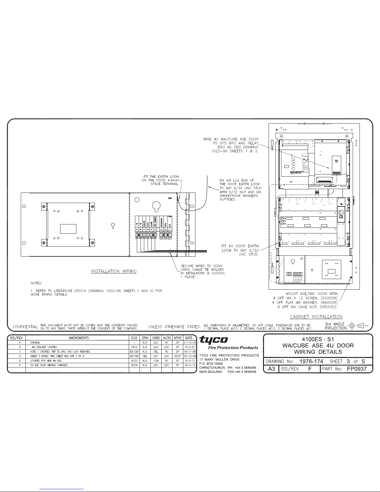
FP0937 FP,4100ES-S1 1976-174,WA/CUBE ASE DOOR KIT
DOOR MOUNTING
Both types of brigade door s m o u nt in t h e 4 unit sp ac e at th e bottom of the 4100ES-S1 ca b i net, using 4 x M6 screws, washers
and cage nuts. Cage nuts should already be fitted to the 4100ES-S1 and scr ews supplied with it, but there are spare screws,
washers and cage nuts supplied with this kit in case the others have been lost.
GENERAL WIRING
The WA/CUBE ASE should be powered from the fused DC distribution board on the power supply. It is recommended that the
brigade device does not share its fuse protection with any other equipment, for reliability.
The wiring between the brigade device and the 4100ES-S 1 should be routed neatly as shown in the following drawings, and
secured in place with the cable ties and adhesive tie holders supplied with t he kits.
Fit the protective earth lead between the quick-connect tap on the brigade interface door and an unused stud in the lower right
end of the expansion bay, using the nut and washers supplied with this kit.
WA/CUBE ASE MOUNTING
The WA ASE (Code Red III) or CU B E AS E mu s t be obtained separately . The FP0937 brigade interf ac e d o or is supp l ied
assembled ready to take an WA ASE, which is fastened directly to the spacer bracket by four screws supplied with the kit. To
mount a CUBE ASE, the spacer bracket must be removed and reassembled using the extra 25mm male/female barrel nuts
supplied according to drawing 1976-174 sheet 5 on page 3. The CUBE ASE is fastened directly to the spacer bracket using
four 3/8” PK screws supplied with this kit.
WA/CUBE ASE WIRING
For the WA ASE the pre-fitted wiring must be connected to the 4100ES-S1’s Alarm Relay terminals as shown in 1976-174
sheet 5 on page 3. For the CUBE ASE the FP0740 FAS Interface Module connects to the 4100ES Alarm Relay Card. Set the
three links on the 4100ES Alarm Relay card to the NO positions for a WA ASE and the NC positions for a CUBE ASE.
CENTAUR II ASE MOUNTING
The ASE unit must be obtaine d se p ar at e ly. If it is supplied complete with a body, this must be remov ed b efore fitting the ASE
to the door. The ASE is fastened to the brigade interface door with the two M4 screws and crinkle washers in the kit. The
antenna socket shoul d be fi tted to the tab on the door bel ow the ASE position. See draw i ng 1 9 76 - 17 4 sh eet 1 on p a ge 4 a nd
the ASE installation instructions for details.
CENTAUR II WIRING
The FP0740 ASE FAS module must be connected to the 4100ES-S1’s Alarm Relay terminals and the 2 way ASE connector as
shown in 1976-174 sheet 1 on page 4. Set the three links on the Alarm Relay card to the NC positions.
1 x 4U hinged door, with ASE cover and barrel nuts already fitted
1 x 3 way connector and 1 x 2 way connector for connection to the ASE when it is fitted
1 x FP0740 FAS interface module with red, yellow, blue and white wires
1 x pair of red and black wires for connecting the ASE to the 4100U-S1 DC supply
4 x M6 screws, washers and cage nuts for mounting the door
5 x Cable ties and adhesive cable tie holders for fastening the ASE wiring
1 x green earth lead + nut and washers to earth the door to the expansion bay
2 x M4 x 16 screws and crinkle washers to mount the ASE to the door
2 x ASE TNC Connect Insulation Bush to mount ASE Aerials
2 x ASE TNC Connect Insulation Washer to mount ASE Aerials
These installation instructions.
1 x 4U hinged door with space r b r acket, connector strip, l ab el a nd wi r i ng al r ea d y fitted
4 x M6 screws, washers and cage nuts for mounting the door
5 x Cable ties and adhesive cable tie holders for fastening the WA/CUBE ASE wiring
1 x green earth lead + nut and washers to earth the door to the expansion bay
4 x 3/8” PK screws for mounting the CUBE ASE on the spacer bracket
4 x 25mm male/female barrel nuts for the WA/CUBE ASE mounting option
4 x M4 x 10 screws with washers for mo unt ing the WA ASE on the spacer b rac ket
3 x 15K resistors
These installation i nst r uc t i on s an d lit e rature LT0316.
Manufactured by: Tyco Fire Protection Products
17 Mary Muller Dri ve, PO Box 19-545
Christchurch, New Zealand
Tel +64-3-389 5096
Fax +64-3-389-5938
LT0393 Issue 1.4 23 February 2015 Page 1 of 4
Distributed
by:
Page 2
Page 3

Page 4

 Loading...